EP4080622A1 - Stainless steel for proton exchange membrane fuel cell separator and production method thereof - Google Patents
Stainless steel for proton exchange membrane fuel cell separator and production method thereof Download PDFInfo
- Publication number
- EP4080622A1 EP4080622A1 EP19956948.4A EP19956948A EP4080622A1 EP 4080622 A1 EP4080622 A1 EP 4080622A1 EP 19956948 A EP19956948 A EP 19956948A EP 4080622 A1 EP4080622 A1 EP 4080622A1
- Authority
- EP
- European Patent Office
- Prior art keywords
- processing
- less
- stainless steel
- weight
- solution
- Prior art date
- Legal status (The legal status is an assumption and is not a legal conclusion. Google has not performed a legal analysis and makes no representation as to the accuracy of the status listed.)
- Pending
Links
- 229910001220 stainless steel Inorganic materials 0.000 title claims abstract description 69
- 239000010935 stainless steel Substances 0.000 title claims abstract description 69
- 239000000446 fuel Substances 0.000 title claims abstract description 65
- 238000004519 manufacturing process Methods 0.000 title claims abstract description 36
- 239000012528 membrane Substances 0.000 title description 6
- 238000012545 processing Methods 0.000 claims abstract description 108
- 230000007797 corrosion Effects 0.000 claims abstract description 56
- 238000005260 corrosion Methods 0.000 claims abstract description 56
- 230000004048 modification Effects 0.000 claims abstract description 37
- 238000012986 modification Methods 0.000 claims abstract description 37
- 229920000642 polymer Polymers 0.000 claims abstract description 36
- 238000000034 method Methods 0.000 claims abstract description 32
- 239000000463 material Substances 0.000 claims description 53
- 238000005530 etching Methods 0.000 claims description 44
- 230000006641 stabilisation Effects 0.000 claims description 42
- 238000011105 stabilization Methods 0.000 claims description 42
- 238000005238 degreasing Methods 0.000 claims description 29
- 229910052739 hydrogen Inorganic materials 0.000 claims description 23
- 238000007654 immersion Methods 0.000 claims description 22
- 238000002161 passivation Methods 0.000 claims description 22
- PXGOKWXKJXAPGV-UHFFFAOYSA-N Fluorine Chemical compound FF PXGOKWXKJXAPGV-UHFFFAOYSA-N 0.000 claims description 18
- 229910052799 carbon Inorganic materials 0.000 claims description 18
- 239000011737 fluorine Substances 0.000 claims description 18
- 229910052731 fluorine Inorganic materials 0.000 claims description 18
- 229910052804 chromium Inorganic materials 0.000 claims description 17
- MHAJPDPJQMAIIY-UHFFFAOYSA-N Hydrogen peroxide Chemical compound OO MHAJPDPJQMAIIY-UHFFFAOYSA-N 0.000 claims description 16
- 229910052757 nitrogen Inorganic materials 0.000 claims description 15
- 229910052748 manganese Inorganic materials 0.000 claims description 13
- 229910052710 silicon Inorganic materials 0.000 claims description 12
- 229910052719 titanium Inorganic materials 0.000 claims description 11
- 229910052802 copper Inorganic materials 0.000 claims description 10
- 229910052758 niobium Inorganic materials 0.000 claims description 10
- 239000012535 impurity Substances 0.000 claims description 8
- 229910052717 sulfur Inorganic materials 0.000 claims description 8
- 229910052742 iron Inorganic materials 0.000 claims description 6
- -1 nitrate ions Chemical class 0.000 claims description 5
- 229910002651 NO3 Inorganic materials 0.000 claims description 4
- QAOWNCQODCNURD-UHFFFAOYSA-L Sulfate Chemical compound [O-]S([O-])(=O)=O QAOWNCQODCNURD-UHFFFAOYSA-L 0.000 claims description 4
- 239000003112 inhibitor Substances 0.000 claims description 4
- 229910052759 nickel Inorganic materials 0.000 claims description 3
- 230000005611 electricity Effects 0.000 abstract description 8
- 230000000052 comparative effect Effects 0.000 description 62
- QAOWNCQODCNURD-UHFFFAOYSA-N Sulfuric acid Chemical compound OS(O)(=O)=O QAOWNCQODCNURD-UHFFFAOYSA-N 0.000 description 38
- 239000000243 solution Substances 0.000 description 27
- 239000011651 chromium Substances 0.000 description 21
- 229940032330 sulfuric acid Drugs 0.000 description 19
- 239000011259 mixed solution Substances 0.000 description 18
- 239000001257 hydrogen Substances 0.000 description 17
- 239000011572 manganese Substances 0.000 description 16
- 229910052760 oxygen Inorganic materials 0.000 description 16
- QVGXLLKOCUKJST-UHFFFAOYSA-N atomic oxygen Chemical compound [O] QVGXLLKOCUKJST-UHFFFAOYSA-N 0.000 description 15
- 239000001301 oxygen Substances 0.000 description 15
- UFHFLCQGNIYNRP-UHFFFAOYSA-N Hydrogen Chemical compound [H][H] UFHFLCQGNIYNRP-UHFFFAOYSA-N 0.000 description 14
- XEEYBQQBJWHFJM-UHFFFAOYSA-N Iron Chemical compound [Fe] XEEYBQQBJWHFJM-UHFFFAOYSA-N 0.000 description 13
- GRYLNZFGIOXLOG-UHFFFAOYSA-N Nitric acid Chemical compound O[N+]([O-])=O GRYLNZFGIOXLOG-UHFFFAOYSA-N 0.000 description 13
- 239000010949 copper Substances 0.000 description 13
- 229910017604 nitric acid Inorganic materials 0.000 description 13
- 239000010936 titanium Substances 0.000 description 13
- 230000008569 process Effects 0.000 description 11
- IJGRMHOSHXDMSA-UHFFFAOYSA-N Atomic nitrogen Chemical compound N#N IJGRMHOSHXDMSA-UHFFFAOYSA-N 0.000 description 10
- 239000010955 niobium Substances 0.000 description 10
- 238000000576 coating method Methods 0.000 description 9
- QDOXWKRWXJOMAK-UHFFFAOYSA-N dichromium trioxide Chemical compound O=[Cr]O[Cr]=O QDOXWKRWXJOMAK-UHFFFAOYSA-N 0.000 description 9
- 239000000126 substance Substances 0.000 description 9
- OKTJSMMVPCPJKN-UHFFFAOYSA-N Carbon Chemical compound [C] OKTJSMMVPCPJKN-UHFFFAOYSA-N 0.000 description 8
- VYZAMTAEIAYCRO-UHFFFAOYSA-N Chromium Chemical compound [Cr] VYZAMTAEIAYCRO-UHFFFAOYSA-N 0.000 description 8
- KRHYYFGTRYWZRS-UHFFFAOYSA-N Fluorane Chemical compound F KRHYYFGTRYWZRS-UHFFFAOYSA-N 0.000 description 8
- 239000011248 coating agent Substances 0.000 description 8
- 238000011156 evaluation Methods 0.000 description 8
- XLYOFNOQVPJJNP-UHFFFAOYSA-N water Substances O XLYOFNOQVPJJNP-UHFFFAOYSA-N 0.000 description 8
- 239000007789 gas Substances 0.000 description 7
- 229960002163 hydrogen peroxide Drugs 0.000 description 7
- PWHULOQIROXLJO-UHFFFAOYSA-N Manganese Chemical compound [Mn] PWHULOQIROXLJO-UHFFFAOYSA-N 0.000 description 5
- 238000006243 chemical reaction Methods 0.000 description 5
- 239000004020 conductor Substances 0.000 description 5
- 230000003628 erosive effect Effects 0.000 description 5
- 238000005259 measurement Methods 0.000 description 5
- 229960005419 nitrogen Drugs 0.000 description 5
- 230000009467 reduction Effects 0.000 description 5
- XUIMIQQOPSSXEZ-UHFFFAOYSA-N Silicon Chemical compound [Si] XUIMIQQOPSSXEZ-UHFFFAOYSA-N 0.000 description 4
- 230000008901 benefit Effects 0.000 description 4
- 230000000593 degrading effect Effects 0.000 description 4
- 239000010931 gold Substances 0.000 description 4
- 229910052751 metal Inorganic materials 0.000 description 4
- 239000002184 metal Substances 0.000 description 4
- 239000000203 mixture Substances 0.000 description 4
- 239000005416 organic matter Substances 0.000 description 4
- 239000010703 silicon Substances 0.000 description 4
- PXHVJJICTQNCMI-UHFFFAOYSA-N Nickel Chemical compound [Ni] PXHVJJICTQNCMI-UHFFFAOYSA-N 0.000 description 3
- KWYUFKZDYYNOTN-UHFFFAOYSA-M Potassium hydroxide Chemical compound [OH-].[K+] KWYUFKZDYYNOTN-UHFFFAOYSA-M 0.000 description 3
- HEMHJVSKTPXQMS-UHFFFAOYSA-M Sodium hydroxide Chemical compound [OH-].[Na+] HEMHJVSKTPXQMS-UHFFFAOYSA-M 0.000 description 3
- 229910000831 Steel Inorganic materials 0.000 description 3
- RTAQQCXQSZGOHL-UHFFFAOYSA-N Titanium Chemical compound [Ti] RTAQQCXQSZGOHL-UHFFFAOYSA-N 0.000 description 3
- 238000004833 X-ray photoelectron spectroscopy Methods 0.000 description 3
- 230000015572 biosynthetic process Effects 0.000 description 3
- 230000003749 cleanliness Effects 0.000 description 3
- 238000009792 diffusion process Methods 0.000 description 3
- 230000000694 effects Effects 0.000 description 3
- 238000003487 electrochemical reaction Methods 0.000 description 3
- 229910052737 gold Inorganic materials 0.000 description 3
- 230000000704 physical effect Effects 0.000 description 3
- 239000010959 steel Substances 0.000 description 3
- RYGMFSIKBFXOCR-UHFFFAOYSA-N Copper Chemical compound [Cu] RYGMFSIKBFXOCR-UHFFFAOYSA-N 0.000 description 2
- KRHYYFGTRYWZRS-UHFFFAOYSA-M Fluoride anion Chemical compound [F-] KRHYYFGTRYWZRS-UHFFFAOYSA-M 0.000 description 2
- OAICVXFJPJFONN-UHFFFAOYSA-N Phosphorus Chemical compound [P] OAICVXFJPJFONN-UHFFFAOYSA-N 0.000 description 2
- NINIDFKCEFEMDL-UHFFFAOYSA-N Sulfur Chemical compound [S] NINIDFKCEFEMDL-UHFFFAOYSA-N 0.000 description 2
- 238000004458 analytical method Methods 0.000 description 2
- 230000008859 change Effects 0.000 description 2
- 238000009833 condensation Methods 0.000 description 2
- 230000005494 condensation Effects 0.000 description 2
- 230000007423 decrease Effects 0.000 description 2
- 238000010586 diagram Methods 0.000 description 2
- 238000002845 discoloration Methods 0.000 description 2
- 239000003792 electrolyte Substances 0.000 description 2
- 229940091249 fluoride supplement Drugs 0.000 description 2
- 239000010439 graphite Substances 0.000 description 2
- 229910002804 graphite Inorganic materials 0.000 description 2
- GUCVJGMIXFAOAE-UHFFFAOYSA-N niobium atom Chemical compound [Nb] GUCVJGMIXFAOAE-UHFFFAOYSA-N 0.000 description 2
- 230000003647 oxidation Effects 0.000 description 2
- 238000007254 oxidation reaction Methods 0.000 description 2
- 229910052698 phosphorus Inorganic materials 0.000 description 2
- 239000011574 phosphorus Substances 0.000 description 2
- 229910052697 platinum Inorganic materials 0.000 description 2
- 239000005518 polymer electrolyte Substances 0.000 description 2
- 239000010970 precious metal Substances 0.000 description 2
- 238000007670 refining Methods 0.000 description 2
- 238000005096 rolling process Methods 0.000 description 2
- 230000035939 shock Effects 0.000 description 2
- 239000011593 sulfur Substances 0.000 description 2
- 239000004094 surface-active agent Substances 0.000 description 2
- 238000012360 testing method Methods 0.000 description 2
- BVKZGUZCCUSVTD-UHFFFAOYSA-L Carbonate Chemical compound [O-]C([O-])=O BVKZGUZCCUSVTD-UHFFFAOYSA-L 0.000 description 1
- 229920000742 Cotton Polymers 0.000 description 1
- ZOKXTWBITQBERF-UHFFFAOYSA-N Molybdenum Chemical compound [Mo] ZOKXTWBITQBERF-UHFFFAOYSA-N 0.000 description 1
- NHNBFGGVMKEFGY-UHFFFAOYSA-N Nitrate Chemical compound [O-][N+]([O-])=O NHNBFGGVMKEFGY-UHFFFAOYSA-N 0.000 description 1
- BPQQTUXANYXVAA-UHFFFAOYSA-N Orthosilicate Chemical compound [O-][Si]([O-])([O-])[O-] BPQQTUXANYXVAA-UHFFFAOYSA-N 0.000 description 1
- 229910019142 PO4 Inorganic materials 0.000 description 1
- 229910001069 Ti alloy Inorganic materials 0.000 description 1
- WGLPBDUCMAPZCE-UHFFFAOYSA-N Trioxochromium Chemical compound O=[Cr](=O)=O WGLPBDUCMAPZCE-UHFFFAOYSA-N 0.000 description 1
- 239000003929 acidic solution Substances 0.000 description 1
- 230000002378 acidificating effect Effects 0.000 description 1
- 230000009471 action Effects 0.000 description 1
- 239000000654 additive Substances 0.000 description 1
- 230000000996 additive effect Effects 0.000 description 1
- 230000002411 adverse Effects 0.000 description 1
- 238000003915 air pollution Methods 0.000 description 1
- 239000012670 alkaline solution Substances 0.000 description 1
- 229910045601 alloy Inorganic materials 0.000 description 1
- 239000000956 alloy Substances 0.000 description 1
- 229910001566 austenite Inorganic materials 0.000 description 1
- 229910000963 austenitic stainless steel Inorganic materials 0.000 description 1
- QRUDEWIWKLJBPS-UHFFFAOYSA-N benzotriazole Chemical compound C1=CC=C2N[N][N]C2=C1 QRUDEWIWKLJBPS-UHFFFAOYSA-N 0.000 description 1
- 239000012964 benzotriazole Substances 0.000 description 1
- 230000015556 catabolic process Effects 0.000 description 1
- 229910000423 chromium oxide Inorganic materials 0.000 description 1
- 230000006378 damage Effects 0.000 description 1
- 230000007812 deficiency Effects 0.000 description 1
- 238000006731 degradation reaction Methods 0.000 description 1
- 230000002542 deteriorative effect Effects 0.000 description 1
- 238000007599 discharging Methods 0.000 description 1
- 239000012153 distilled water Substances 0.000 description 1
- 238000005868 electrolysis reaction Methods 0.000 description 1
- 238000010828 elution Methods 0.000 description 1
- 239000003995 emulsifying agent Substances 0.000 description 1
- 239000002803 fossil fuel Substances 0.000 description 1
- PCHJSUWPFVWCPO-UHFFFAOYSA-N gold Chemical compound [Au] PCHJSUWPFVWCPO-UHFFFAOYSA-N 0.000 description 1
- 150000002431 hydrogen Chemical class 0.000 description 1
- 230000005660 hydrophilic surface Effects 0.000 description 1
- 230000002209 hydrophobic effect Effects 0.000 description 1
- 230000006872 improvement Effects 0.000 description 1
- 230000006698 induction Effects 0.000 description 1
- 238000003780 insertion Methods 0.000 description 1
- 230000037431 insertion Effects 0.000 description 1
- 239000007788 liquid Substances 0.000 description 1
- 239000011159 matrix material Substances 0.000 description 1
- 229910052750 molybdenum Inorganic materials 0.000 description 1
- 239000011733 molybdenum Substances 0.000 description 1
- 230000007935 neutral effect Effects 0.000 description 1
- 150000004767 nitrides Chemical class 0.000 description 1
- 230000035699 permeability Effects 0.000 description 1
- 239000010452 phosphate Substances 0.000 description 1
- NBIIXXVUZAFLBC-UHFFFAOYSA-K phosphate Chemical compound [O-]P([O-])([O-])=O NBIIXXVUZAFLBC-UHFFFAOYSA-K 0.000 description 1
- 239000004033 plastic Substances 0.000 description 1
- 238000010248 power generation Methods 0.000 description 1
- 238000003672 processing method Methods 0.000 description 1
- 239000003381 stabilizer Substances 0.000 description 1
- 238000009628 steelmaking Methods 0.000 description 1
- 238000003860 storage Methods 0.000 description 1
- CADICXFYUNYKGD-UHFFFAOYSA-N sulfanylidenemanganese Chemical compound [Mn]=S CADICXFYUNYKGD-UHFFFAOYSA-N 0.000 description 1
- 239000010938 white gold Substances 0.000 description 1
- 229910000832 white gold Inorganic materials 0.000 description 1
Images



Classifications
-
- C—CHEMISTRY; METALLURGY
- C22—METALLURGY; FERROUS OR NON-FERROUS ALLOYS; TREATMENT OF ALLOYS OR NON-FERROUS METALS
- C22C—ALLOYS
- C22C38/00—Ferrous alloys, e.g. steel alloys
- C22C38/18—Ferrous alloys, e.g. steel alloys containing chromium
- C22C38/38—Ferrous alloys, e.g. steel alloys containing chromium with more than 1.5% by weight of manganese
-
- H—ELECTRICITY
- H01—ELECTRIC ELEMENTS
- H01M—PROCESSES OR MEANS, e.g. BATTERIES, FOR THE DIRECT CONVERSION OF CHEMICAL ENERGY INTO ELECTRICAL ENERGY
- H01M8/00—Fuel cells; Manufacture thereof
- H01M8/02—Details
- H01M8/0202—Collectors; Separators, e.g. bipolar separators; Interconnectors
- H01M8/0204—Non-porous and characterised by the material
- H01M8/0206—Metals or alloys
- H01M8/0208—Alloys
- H01M8/021—Alloys based on iron
-
- C—CHEMISTRY; METALLURGY
- C22—METALLURGY; FERROUS OR NON-FERROUS ALLOYS; TREATMENT OF ALLOYS OR NON-FERROUS METALS
- C22C—ALLOYS
- C22C38/00—Ferrous alloys, e.g. steel alloys
- C22C38/001—Ferrous alloys, e.g. steel alloys containing N
-
- C—CHEMISTRY; METALLURGY
- C22—METALLURGY; FERROUS OR NON-FERROUS ALLOYS; TREATMENT OF ALLOYS OR NON-FERROUS METALS
- C22C—ALLOYS
- C22C38/00—Ferrous alloys, e.g. steel alloys
- C22C38/002—Ferrous alloys, e.g. steel alloys containing In, Mg, or other elements not provided for in one single group C22C38/001 - C22C38/60
-
- C—CHEMISTRY; METALLURGY
- C22—METALLURGY; FERROUS OR NON-FERROUS ALLOYS; TREATMENT OF ALLOYS OR NON-FERROUS METALS
- C22C—ALLOYS
- C22C38/00—Ferrous alloys, e.g. steel alloys
- C22C38/02—Ferrous alloys, e.g. steel alloys containing silicon
-
- C—CHEMISTRY; METALLURGY
- C22—METALLURGY; FERROUS OR NON-FERROUS ALLOYS; TREATMENT OF ALLOYS OR NON-FERROUS METALS
- C22C—ALLOYS
- C22C38/00—Ferrous alloys, e.g. steel alloys
- C22C38/04—Ferrous alloys, e.g. steel alloys containing manganese
-
- C—CHEMISTRY; METALLURGY
- C22—METALLURGY; FERROUS OR NON-FERROUS ALLOYS; TREATMENT OF ALLOYS OR NON-FERROUS METALS
- C22C—ALLOYS
- C22C38/00—Ferrous alloys, e.g. steel alloys
- C22C38/18—Ferrous alloys, e.g. steel alloys containing chromium
- C22C38/20—Ferrous alloys, e.g. steel alloys containing chromium with copper
-
- C—CHEMISTRY; METALLURGY
- C22—METALLURGY; FERROUS OR NON-FERROUS ALLOYS; TREATMENT OF ALLOYS OR NON-FERROUS METALS
- C22C—ALLOYS
- C22C38/00—Ferrous alloys, e.g. steel alloys
- C22C38/18—Ferrous alloys, e.g. steel alloys containing chromium
- C22C38/26—Ferrous alloys, e.g. steel alloys containing chromium with niobium or tantalum
-
- C—CHEMISTRY; METALLURGY
- C22—METALLURGY; FERROUS OR NON-FERROUS ALLOYS; TREATMENT OF ALLOYS OR NON-FERROUS METALS
- C22C—ALLOYS
- C22C38/00—Ferrous alloys, e.g. steel alloys
- C22C38/18—Ferrous alloys, e.g. steel alloys containing chromium
- C22C38/28—Ferrous alloys, e.g. steel alloys containing chromium with titanium or zirconium
-
- C—CHEMISTRY; METALLURGY
- C23—COATING METALLIC MATERIAL; COATING MATERIAL WITH METALLIC MATERIAL; CHEMICAL SURFACE TREATMENT; DIFFUSION TREATMENT OF METALLIC MATERIAL; COATING BY VACUUM EVAPORATION, BY SPUTTERING, BY ION IMPLANTATION OR BY CHEMICAL VAPOUR DEPOSITION, IN GENERAL; INHIBITING CORROSION OF METALLIC MATERIAL OR INCRUSTATION IN GENERAL
- C23C—COATING METALLIC MATERIAL; COATING MATERIAL WITH METALLIC MATERIAL; SURFACE TREATMENT OF METALLIC MATERIAL BY DIFFUSION INTO THE SURFACE, BY CHEMICAL CONVERSION OR SUBSTITUTION; COATING BY VACUUM EVAPORATION, BY SPUTTERING, BY ION IMPLANTATION OR BY CHEMICAL VAPOUR DEPOSITION, IN GENERAL
- C23C22/00—Chemical surface treatment of metallic material by reaction of the surface with a reactive liquid, leaving reaction products of surface material in the coating, e.g. conversion coatings, passivation of metals
- C23C22/05—Chemical surface treatment of metallic material by reaction of the surface with a reactive liquid, leaving reaction products of surface material in the coating, e.g. conversion coatings, passivation of metals using aqueous solutions
- C23C22/06—Chemical surface treatment of metallic material by reaction of the surface with a reactive liquid, leaving reaction products of surface material in the coating, e.g. conversion coatings, passivation of metals using aqueous solutions using aqueous acidic solutions with pH less than 6
- C23C22/48—Chemical surface treatment of metallic material by reaction of the surface with a reactive liquid, leaving reaction products of surface material in the coating, e.g. conversion coatings, passivation of metals using aqueous solutions using aqueous acidic solutions with pH less than 6 not containing phosphates, hexavalent chromium compounds, fluorides or complex fluorides, molybdates, tungstates, vanadates or oxalates
- C23C22/50—Treatment of iron or alloys based thereon
-
- C—CHEMISTRY; METALLURGY
- C23—COATING METALLIC MATERIAL; COATING MATERIAL WITH METALLIC MATERIAL; CHEMICAL SURFACE TREATMENT; DIFFUSION TREATMENT OF METALLIC MATERIAL; COATING BY VACUUM EVAPORATION, BY SPUTTERING, BY ION IMPLANTATION OR BY CHEMICAL VAPOUR DEPOSITION, IN GENERAL; INHIBITING CORROSION OF METALLIC MATERIAL OR INCRUSTATION IN GENERAL
- C23C—COATING METALLIC MATERIAL; COATING MATERIAL WITH METALLIC MATERIAL; SURFACE TREATMENT OF METALLIC MATERIAL BY DIFFUSION INTO THE SURFACE, BY CHEMICAL CONVERSION OR SUBSTITUTION; COATING BY VACUUM EVAPORATION, BY SPUTTERING, BY ION IMPLANTATION OR BY CHEMICAL VAPOUR DEPOSITION, IN GENERAL
- C23C22/00—Chemical surface treatment of metallic material by reaction of the surface with a reactive liquid, leaving reaction products of surface material in the coating, e.g. conversion coatings, passivation of metals
- C23C22/78—Pretreatment of the material to be coated
-
- C—CHEMISTRY; METALLURGY
- C23—COATING METALLIC MATERIAL; COATING MATERIAL WITH METALLIC MATERIAL; CHEMICAL SURFACE TREATMENT; DIFFUSION TREATMENT OF METALLIC MATERIAL; COATING BY VACUUM EVAPORATION, BY SPUTTERING, BY ION IMPLANTATION OR BY CHEMICAL VAPOUR DEPOSITION, IN GENERAL; INHIBITING CORROSION OF METALLIC MATERIAL OR INCRUSTATION IN GENERAL
- C23C—COATING METALLIC MATERIAL; COATING MATERIAL WITH METALLIC MATERIAL; SURFACE TREATMENT OF METALLIC MATERIAL BY DIFFUSION INTO THE SURFACE, BY CHEMICAL CONVERSION OR SUBSTITUTION; COATING BY VACUUM EVAPORATION, BY SPUTTERING, BY ION IMPLANTATION OR BY CHEMICAL VAPOUR DEPOSITION, IN GENERAL
- C23C22/00—Chemical surface treatment of metallic material by reaction of the surface with a reactive liquid, leaving reaction products of surface material in the coating, e.g. conversion coatings, passivation of metals
- C23C22/82—After-treatment
-
- C—CHEMISTRY; METALLURGY
- C23—COATING METALLIC MATERIAL; COATING MATERIAL WITH METALLIC MATERIAL; CHEMICAL SURFACE TREATMENT; DIFFUSION TREATMENT OF METALLIC MATERIAL; COATING BY VACUUM EVAPORATION, BY SPUTTERING, BY ION IMPLANTATION OR BY CHEMICAL VAPOUR DEPOSITION, IN GENERAL; INHIBITING CORROSION OF METALLIC MATERIAL OR INCRUSTATION IN GENERAL
- C23F—NON-MECHANICAL REMOVAL OF METALLIC MATERIAL FROM SURFACE; INHIBITING CORROSION OF METALLIC MATERIAL OR INCRUSTATION IN GENERAL; MULTI-STEP PROCESSES FOR SURFACE TREATMENT OF METALLIC MATERIAL INVOLVING AT LEAST ONE PROCESS PROVIDED FOR IN CLASS C23 AND AT LEAST ONE PROCESS COVERED BY SUBCLASS C21D OR C22F OR CLASS C25
- C23F1/00—Etching metallic material by chemical means
- C23F1/10—Etching compositions
- C23F1/14—Aqueous compositions
- C23F1/16—Acidic compositions
- C23F1/28—Acidic compositions for etching iron group metals
-
- C—CHEMISTRY; METALLURGY
- C23—COATING METALLIC MATERIAL; COATING MATERIAL WITH METALLIC MATERIAL; CHEMICAL SURFACE TREATMENT; DIFFUSION TREATMENT OF METALLIC MATERIAL; COATING BY VACUUM EVAPORATION, BY SPUTTERING, BY ION IMPLANTATION OR BY CHEMICAL VAPOUR DEPOSITION, IN GENERAL; INHIBITING CORROSION OF METALLIC MATERIAL OR INCRUSTATION IN GENERAL
- C23G—CLEANING OR DE-GREASING OF METALLIC MATERIAL BY CHEMICAL METHODS OTHER THAN ELECTROLYSIS
- C23G1/00—Cleaning or pickling metallic material with solutions or molten salts
- C23G1/02—Cleaning or pickling metallic material with solutions or molten salts with acid solutions
- C23G1/04—Cleaning or pickling metallic material with solutions or molten salts with acid solutions using inhibitors
-
- C—CHEMISTRY; METALLURGY
- C23—COATING METALLIC MATERIAL; COATING MATERIAL WITH METALLIC MATERIAL; CHEMICAL SURFACE TREATMENT; DIFFUSION TREATMENT OF METALLIC MATERIAL; COATING BY VACUUM EVAPORATION, BY SPUTTERING, BY ION IMPLANTATION OR BY CHEMICAL VAPOUR DEPOSITION, IN GENERAL; INHIBITING CORROSION OF METALLIC MATERIAL OR INCRUSTATION IN GENERAL
- C23G—CLEANING OR DE-GREASING OF METALLIC MATERIAL BY CHEMICAL METHODS OTHER THAN ELECTROLYSIS
- C23G1/00—Cleaning or pickling metallic material with solutions or molten salts
- C23G1/02—Cleaning or pickling metallic material with solutions or molten salts with acid solutions
- C23G1/04—Cleaning or pickling metallic material with solutions or molten salts with acid solutions using inhibitors
- C23G1/06—Cleaning or pickling metallic material with solutions or molten salts with acid solutions using inhibitors organic inhibitors
- C23G1/063—Cleaning or pickling metallic material with solutions or molten salts with acid solutions using inhibitors organic inhibitors heterocyclic compounds
-
- C—CHEMISTRY; METALLURGY
- C23—COATING METALLIC MATERIAL; COATING MATERIAL WITH METALLIC MATERIAL; CHEMICAL SURFACE TREATMENT; DIFFUSION TREATMENT OF METALLIC MATERIAL; COATING BY VACUUM EVAPORATION, BY SPUTTERING, BY ION IMPLANTATION OR BY CHEMICAL VAPOUR DEPOSITION, IN GENERAL; INHIBITING CORROSION OF METALLIC MATERIAL OR INCRUSTATION IN GENERAL
- C23G—CLEANING OR DE-GREASING OF METALLIC MATERIAL BY CHEMICAL METHODS OTHER THAN ELECTROLYSIS
- C23G1/00—Cleaning or pickling metallic material with solutions or molten salts
- C23G1/02—Cleaning or pickling metallic material with solutions or molten salts with acid solutions
- C23G1/08—Iron or steel
- C23G1/086—Iron or steel solutions containing HF
-
- C—CHEMISTRY; METALLURGY
- C23—COATING METALLIC MATERIAL; COATING MATERIAL WITH METALLIC MATERIAL; CHEMICAL SURFACE TREATMENT; DIFFUSION TREATMENT OF METALLIC MATERIAL; COATING BY VACUUM EVAPORATION, BY SPUTTERING, BY ION IMPLANTATION OR BY CHEMICAL VAPOUR DEPOSITION, IN GENERAL; INHIBITING CORROSION OF METALLIC MATERIAL OR INCRUSTATION IN GENERAL
- C23G—CLEANING OR DE-GREASING OF METALLIC MATERIAL BY CHEMICAL METHODS OTHER THAN ELECTROLYSIS
- C23G1/00—Cleaning or pickling metallic material with solutions or molten salts
- C23G1/14—Cleaning or pickling metallic material with solutions or molten salts with alkaline solutions
- C23G1/16—Cleaning or pickling metallic material with solutions or molten salts with alkaline solutions using inhibitors
-
- C—CHEMISTRY; METALLURGY
- C23—COATING METALLIC MATERIAL; COATING MATERIAL WITH METALLIC MATERIAL; CHEMICAL SURFACE TREATMENT; DIFFUSION TREATMENT OF METALLIC MATERIAL; COATING BY VACUUM EVAPORATION, BY SPUTTERING, BY ION IMPLANTATION OR BY CHEMICAL VAPOUR DEPOSITION, IN GENERAL; INHIBITING CORROSION OF METALLIC MATERIAL OR INCRUSTATION IN GENERAL
- C23G—CLEANING OR DE-GREASING OF METALLIC MATERIAL BY CHEMICAL METHODS OTHER THAN ELECTROLYSIS
- C23G1/00—Cleaning or pickling metallic material with solutions or molten salts
- C23G1/14—Cleaning or pickling metallic material with solutions or molten salts with alkaline solutions
- C23G1/19—Iron or steel
-
- C—CHEMISTRY; METALLURGY
- C23—COATING METALLIC MATERIAL; COATING MATERIAL WITH METALLIC MATERIAL; CHEMICAL SURFACE TREATMENT; DIFFUSION TREATMENT OF METALLIC MATERIAL; COATING BY VACUUM EVAPORATION, BY SPUTTERING, BY ION IMPLANTATION OR BY CHEMICAL VAPOUR DEPOSITION, IN GENERAL; INHIBITING CORROSION OF METALLIC MATERIAL OR INCRUSTATION IN GENERAL
- C23G—CLEANING OR DE-GREASING OF METALLIC MATERIAL BY CHEMICAL METHODS OTHER THAN ELECTROLYSIS
- C23G5/00—Cleaning or de-greasing metallic material by other methods; Apparatus for cleaning or de-greasing metallic material with organic solvents
- C23G5/06—Cleaning or de-greasing metallic material by other methods; Apparatus for cleaning or de-greasing metallic material with organic solvents using emulsions
-
- H—ELECTRICITY
- H01—ELECTRIC ELEMENTS
- H01M—PROCESSES OR MEANS, e.g. BATTERIES, FOR THE DIRECT CONVERSION OF CHEMICAL ENERGY INTO ELECTRICAL ENERGY
- H01M8/00—Fuel cells; Manufacture thereof
- H01M8/02—Details
- H01M8/0202—Collectors; Separators, e.g. bipolar separators; Interconnectors
- H01M8/0204—Non-porous and characterised by the material
- H01M8/0223—Composites
- H01M8/0228—Composites in the form of layered or coated products
-
- H—ELECTRICITY
- H01—ELECTRIC ELEMENTS
- H01M—PROCESSES OR MEANS, e.g. BATTERIES, FOR THE DIRECT CONVERSION OF CHEMICAL ENERGY INTO ELECTRICAL ENERGY
- H01M8/00—Fuel cells; Manufacture thereof
- H01M8/10—Fuel cells with solid electrolytes
- H01M2008/1095—Fuel cells with polymeric electrolytes
-
- H—ELECTRICITY
- H01—ELECTRIC ELEMENTS
- H01M—PROCESSES OR MEANS, e.g. BATTERIES, FOR THE DIRECT CONVERSION OF CHEMICAL ENERGY INTO ELECTRICAL ENERGY
- H01M50/00—Constructional details or processes of manufacture of the non-active parts of electrochemical cells other than fuel cells, e.g. hybrid cells
- H01M50/40—Separators; Membranes; Diaphragms; Spacing elements inside cells
- H01M50/403—Manufacturing processes of separators, membranes or diaphragms
-
- H—ELECTRICITY
- H01—ELECTRIC ELEMENTS
- H01M—PROCESSES OR MEANS, e.g. BATTERIES, FOR THE DIRECT CONVERSION OF CHEMICAL ENERGY INTO ELECTRICAL ENERGY
- H01M50/00—Constructional details or processes of manufacture of the non-active parts of electrochemical cells other than fuel cells, e.g. hybrid cells
- H01M50/40—Separators; Membranes; Diaphragms; Spacing elements inside cells
- H01M50/409—Separators, membranes or diaphragms characterised by the material
- H01M50/431—Inorganic material
Definitions
- the present disclosure relates to stainless steel for a polymer fuel cell separator used in an electricity generator using a hydrogen fuel, and a method of manufacturing the stainless steel, and more particularly, to stainless steel for a polymer fuel cell separator and a method of manufacturing the stainless steel, in which a surface modification technique based on wet processing is applied to a surface of stainless steel used for an anode, a cathode, etc., of a stack that generates electricity, thus providing corrosion resistance and electrical conductivity and preventing moisture from being formed.
- the present disclosure also relates to stainless steel for a polymer fuel cell separator and a method of manufacturing the stainless steel, in which durability is superior with electrical, chemical, and physical stability by using a surface modification technique based on a chemical method instead of a coating method or a passivation processing method.
- a hydrogen fuel cell is an eco-friendly electricity generator that generates water and electrical energy by using hydrogen and oxygen in the atmosphere, reversely to a method of generating hydrogen and oxygen based on water electrolysis with an eco-friendly electric power generation system that has emerged as a scheme to replace a fossil fuel and reduce air pollution.
- a polymer fuel cell a proton exchange membrane fuel cell: PEMFC
- PEMFC proton exchange membrane fuel cell
- the polymer fuel cell includes a polymer electrolyte membrane, an electrode, a gas diffusion layer (GDL), and a separator.
- the separator used in the polymer fuel cell has a structure having formed therein a channel through which hydrogen and oxygen may flow, and separates each unit cell, serves as a support of a membrane electrode assembly (MEA), provides a path through which hydrogen and oxygen may flow, and plays an important role as a current collector that delivers generated energy.
- MEA membrane electrode assembly
- PEMFC polymer fuel cell
- the polymer fuel cell includes a polymer electrolyte membrane, an electrode, a GDL, and a separator.
- the separator used in the polymer fuel cell has a structure having formed therein a channel through which hydrogen and oxygen may flow, and separates each unit cell, serves as a support of a membrane electrode assembly (MEA), provides a path through which hydrogen and oxygen may flow, and plays an important role of a current collector that delivers generated energy.
- MEA membrane electrode assembly
- a fuel cell separator which refers to a fuel electrode (an anode) and an air electrode (a cathode), enables an electrochemical reaction between hydrogen and oxygen.
- the fuel cell separator requires superior electrical conductivity to facilitate movement of electrons and needs to guarantee corrosion resistance to prevent corrosion in a reaction between the anode and the cathode.
- moisture condensation a flooding phenomenon
- excellent hydrophilicity is required.
- the fuel cell separator requires superior thermal and electrical conductivity, a mechanical strength for preventing deformation and avoiding destruction due to vibration or shocks, dimensional stability, chemical resistance, etc., and graphite, a Ti alloy, conductive plastic, stainless steel, etc., have such properties, and as a metal electrode plate, stainless steel is used for excellent thermal conductivity, formability, dimensional stability, and corrosion resistance, and conductivity is given to the electrode plate by coating the electrode plate or forming a conductive film on the electrode plate.
- a carbon (or graphite) -based separator has a high gas or liquid permeability and poor mechanical strength and moldability, and has a high processing cost.
- a stainless metal separator has superior gas tightness and high thermal and electrical conductivity, and is able to be thinned, guaranteeing lightweightness and excellent shock resistance.
- the stainless metal separator has the advantage of reducing the price of the separator with excellent production yield in application of a thin plate forming process such as stamping, hydroforming, etc.
- Stainless steel has an excellent thinning property and formability, but has a high contact resistance due to a Cr 2 O 3 passivation film formed on a surface of the stainless steel, resulting in low electrical conductivity.
- a conductive material such as Au, Pt, C, etc.
- a conductive material is coated onto a surface of the fuel cell separator to give conductivity in a final process, thereby improving electrical conductivity.
- Stainless steel is made of an alloy including iron and chromium or including iron, chromium, and nickel, and the corrosion resistance of the stainless steel may be excellent by forming a very thin chrome oxide layer (Cr 2 O 3 ) in which chromium (Cr) is combined with the surface of the steel to block intrusion of oxygen into a metal matrix.
- Cr 2 O 3 chrome oxide layer
- Cr 2 O 3 chrome oxide layer formed on the surface of stainless steel is formed firmly, corrosion resistance may be superior, but as the firm oxide layer is formed, electrical conductivity may be degraded.
- a method of coating or carbon coating using gold or white gold, which is precious metal with excellent corrosion resistance and electrical conductivity, and a method of forming a conductive film after stainless passivation are applied.
- Korean Patent Publication Gazette No. 10-2015-0074768 discloses austenite-based stainless steel for a fuel cell and a method of manufacturing the stainless steel.
- the present disclosure provides stainless steel for a polymer fuel cell separator and a method of manufacturing the stainless steel, in which a chemical surface modification technique, instead of coating or conductive film formation, is applied to simultaneously implement corrosion resistance and electrical conductivity that are mechanical properties for use as a fuel cell separator, thereby securing a superior interfacial contact resistance.
- the present disclosure also provides stainless steel for a polymer fuel cell separator and a method of manufacturing the stainless steel, in which a thermal oxide film generated in a steel making and rolling process or a natural oxide film formed in an atmosphere environment are removed by etching and a chemical surface modification technique is applied, such that the stainless steel has a contact resistance of 10 to 35 m ⁇ cm 2 under a pressure of 1.0 MPa, and has a contact angle of 30° ⁇ 70° in a contact angle (water droplet formation) test to provide a high-temperature potentiodynamic corrosion resistance of 15 ⁇ A/cm 2 or less and remove moisture condensation in a mixed solution of sulfuric acid of 0.1 N and hydrofluoric acid of 2 ppm at a temperature of 80 °C that is a polymer fuel cell environment temperature.
- stainless steel for a polymer fuel cell separator includes, by weight%, C: 0.01 ⁇ 0.08%, Si: 0.3 ⁇ 1.0%, Mn: 0.3 ⁇ 2.0%, Cr: 15 ⁇ 35%, Cu: 1.0% or less, N: 0.01 ⁇ 0.05%, Ti: 0.3% or less, Nb: 0.3% or less, and as the rest, Fe and other inevitable impurities, and a surface modification layer having an interfacial contact resistance of 10 ⁇ 35 m ⁇ cm 2 through surface modification processing, in which a potentiodynamic corrosion resistance is 1.0 ⁇ 15.0 ⁇ A/cm 2 and a contact angle is 30 ⁇ 70°.
- the stainless steel may further include one or more kinds of P: 0.14 weight% or less, S: 0.03 weight% or less, H: 0.004 weight% or less, and O: 0.007 weight% or less.
- the surface modification processing may include degreasing processing of performing immersion in a degreasing solution, etching and desmut processing of performing etching with an etching solution and desmut processing in a desmut solution, and surface stabilization processing of performing immersion in a surface stabilization solution.
- a method of manufacturing stainless steel for a polymer fuel cell separator includes, (a) providing a stainless base material including, by weight%, C: 0.01 ⁇ 0.08%, Si: 0.3 ⁇ 1.0%, Mn: 0.3 ⁇ 2.0%, Cr: 15 ⁇ 35%, Cu: 1.0% or less, Ni: 10 ⁇ 25%, N: 0.01 ⁇ 0.05%, Ti: 0.3% or less, Nb: 0.3% or less, and as the rest, Fe and other inevitable impurities, the stainless base material having a passivation film formed on a surface thereof, (b) performing degreasing processing by immersing the surface of the stainless base material in a degreasing solution, (c) after etching the degreasing-processed stainless base material with an etching solution, performing desmut processing with a desmut solution, and (d) performing surface stabilization on the etched and desmut-processed stainless base material with a surface stabilization solution, in which after (d), the
- the stainless base material may further include one or more kinds of P: 0.14 weight% or less, S: 0.03 weight% or less, H: 0.004 weight% or less, and O: 0.007 weight% or less.
- the degreasing processing may include performing immersion in the degreasing solution at 30 ⁇ 70°C for 0.5 ⁇ 5 minutes.
- the etching processing may include performing immersion for 0.2 ⁇ 2 minutes in an etching solution, heated to 40 ⁇ 80°C, including at least two or more of 2.5 ⁇ 6.2 mols of sulfate ions, 0.1 ⁇ 2.0 mols of nitrate ions, and 1.0 ⁇ 5.0 mols of fluorine
- the desmut processing may include performing immersion for 0.5 ⁇ 2 minutes in a desmut solution, heated to 40 ⁇ 80°C, including 1.5 ⁇ 6.0 mols of hydrogen peroxide, 1.0 ⁇ 4.0 mols of fluorine, and 0.001 ⁇ 0.01 mol of a corrosion inhibitor.
- the method may further include (e) performing stabilization thermal processing for stabilization of the surface-stabilized stainless base material.
- the stabilization thermal processing may be performed at 150 ⁇ 250°C for 1 ⁇ 10 minutes.
- Stainless steel for a polymer fuel cell separator and a method of manufacturing the stainless steel according to the present disclosure modify a surface passivation film without corrosion or pitting with respect to a stainless base material having a passivation film on a surface thereof, thereby securing a low interfacial contact resistance, superior corrosion resistance, and excellent wettability.
- the stainless steel for a polymer fuel cell separator and the method of manufacturing the stainless steel according to the present disclosure may provide a superior interfacial contact resistance and corrosion resistance without additional coating of precious metal or conductive materials, and provide excellent surface wettability without further hydrophilic processing or coating.
- Stainless steel for a polymer fuel cell separator may include, by weight%, C: 0.01 ⁇ 0.08%, Si: 0.3 ⁇ 1.0%, Mn: 0.3 ⁇ 2.0%, Cr: 15 ⁇ 35%, Cu: 1.0% or less, N: 0.01 ⁇ 0.05%, Ti: 0.3% or less, Nb: 0.3% or less, and as the rest, Fe and other inevitable impurities, and may include a surface modification layer having an interfacial contact resistance of 10 ⁇ 35 m ⁇ cm 2 under a pressure of 1.0 MPa through surface modification processing.
- the stainless steel for the polymer fuel cell separator according to an embodiment of the present disclosure may further include one or more kinds of P: 0.14 weight% or less, S: 0.03 weight% or less, H: 0.004 weight% or less, and O: 0.007 weight% or less.
- the stainless steel for the polymer fuel cell separator may have a potentiodynamic corrosion resistance of 15 ⁇ A/cm 2 or less (sulfuric acid of 0.1 N and hydrofluoric acid of 2 ppm at 80 °C, SCE), more preferably, 1.0 ⁇ 15.0 ⁇ A/cm 2 , and a contact angle of 70° or less, more preferably, a contact angle range of 30° ⁇ 70°, when a droplet of 3 ⁇ l is dropped.
- Carbon (C) is an essential element for increasing the strength of austenitic stainless steel, and may be preferably added at a content ratio of 0.01 ⁇ 0.08 weight% to a total weight.
- amount of addition of carbon (C) is less than 0.01 weight%, a refining price for making a high-purity product may increase.
- amount of addition of carbon (C) exceeds 0.08 weight%, processability and toughness may be degraded due to increase of impurities.
- Silicon (Si) is an effective element for deoxidation, and may be preferably added at a content ratio of 0.3 ⁇ 1.0 weight% to a total weight.
- a refining price may be increased.
- a material may be hardened, degrading toughness and thus formability.
- Manganese (Mn) is an essential element for increasing austenitic phase stability, and may be preferably added at a content ratio of 0.3 ⁇ 2.0 weight% to a total weight. When the amount of addition of manganese (Mn) is less than 0.3 weight%, a target physical property may be difficult to secure. In contrast, when the amount of addition of manganese (Mn) exceeds 2.0 weight%, corrosion resistance may be degraded due to excessive addition of manganese (Mn).
- Chromium (Cr) is an essential element for improving corrosion resistance and oxidation resistance in an operating environment of a fuel cell, and may be preferably added at a content ratio of 15 ⁇ 35 weight% to a total weight.
- the amount of addition of chromium (Cr) is less than 15 weight%, it is difficult to secure proper oxidation resistance in the operating environment of the fuel cell.
- the amount of addition of chromium (Cr) exceeds 35 weight%, a manufacturing cost may be increased and toughness may be degraded, due to addition more than necessary.
- Copper is an economical additive element that may substitute for expensive molybdenum (Mo) to increase pitting resistance in an acidic atmosphere where the fuel cell operates.
- Mo molybdenum
- Cu is limited to 1.0 weight% or less to the total weight of the stainless steel.
- Nitrogen (N) which is an element for forming a nitride, exists interstitially, such that when N is contained excessively, it may be an unfavorable to elongation rate and yield point elongation in spite of increase of strength.
- nitrogen may be preferably limited to a content ratio of 0.01 ⁇ 0.05 weight% to the total weight of the stainless steel.
- Titanium (Ti) is an effective element for forming C and N of the steel into a carbonitride, but may degrade toughness when added excessively. Thus, in the present disclosure, in consideration of this, Ti is limited to 0.3 weight% or less to the total weight of the stainless steel.
- Niobium is an effective element for forming C and N of the steel into a carbonitride, but may degrade toughness when added excessively.
- Ti is limited to 0.3 weight% or less to the total weight of the stainless steel.
- Phosphorus (P) reduces toughness as well as corrosion resistance, and thus in the present disclosure, is limited to 0.14 weight% or less to the total weight of the stainless steel.
- S may form manganese sulfide (MnS) that becomes a starting point of corrosion and thus reduces corrosion resistance, and thus in the present disclosure, in consideration of this, S is limited to 0.03 weight% to the total weight of the stainless steel.
- MnS manganese sulfide
- Hydrogen (H) and oxygen (O), which are inevitably added impurities, may be preferably limited strictly to 0.004 weight% or less and 0.007 weight% or less, respectively, to the total weight of the stainless steel of the present disclosure.
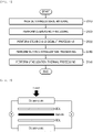
- FIG. 1 is a flowchart illustrating a method of manufacturing stainless steel for a polymer fuel cell separator, according to an embodiment of the present disclosure.
- a method of manufacturing stainless steel for a polymer fuel cell separator may include stainless base material providing operation S110, degreasing processing operation S120, etching and desmut processing operation S130, and surface stabilization processing operation S140.
- the method of manufacturing stainless steel for a polymer fuel cell separator according to an embodiment of the present disclosure may further include stabilization thermal-processing operation S150.
- the stabilization thermal-processing operation S150 may not be necessarily performed and may be omitted depending on needs.
- the stainless base material includes, by weight%, C: 0.01 ⁇ 0.08%, Si: 0.3 ⁇ 1.0%, Mn: 0.3 ⁇ 2.0%, Cr: 15 ⁇ 35%, Cu: 1.0% or less, N: 0.01 ⁇ 0.05%, Ti: 0.3% or less, Nb: 0.3% or less, and as the reset, Fe and other inevitable impurities, and has a passivation film formed on a surface thereof.
- the stainless base material may further include one or more kinds of P: 0.14 weight% or less, S: 0.03 weight% or less, H: 0.004 weight% or less, and O: 0.007 weight% or less.
- the passivation film may cover the surface of the stainless base material.
- the passivation film may include Cr 2 O 3 .
- the passivation film may be formed on a top surface or a bottom surface of the stainless base material or both the top surface and the bottom surface.
- the stainless base material has an excellent thinning property and formability, but has a high electrical resistance due to the Cr 2 O 3 passivation film formed on the surface thereof, resulting in low electrical conductivity.
- the stainless base material may have, but not limited to, a thickness of 0.05 ⁇ 10 mm.
- the stainless base material may have a high contact resistance of 200 ⁇ 500 m ⁇ cm 2 under a pressure of 1.0 MPa due to the Cr 2 O 3 passivation film generated on the surface thereof. Therefore, to use the stainless base material as the fuel cell separator, low contact resistance needs to be secured.
- the surface of the stainless base material may be degreased by being immersed in a degreasing solution.
- the degreasing processing may be performed to remove an organic matter such as the Cr 2 O 3 passivation film attached onto the surface of the stainless base material, etc.
- an acidic solution, a neutral solution, or an alkaline solution in the degreasing processing and any solution capable of removing an organic matter adsorbed in the rolling process of the stainless base material may be used limitlessly.
- the degreasing solution may include 0.1 ⁇ 3 mols of one or more kinds of sodium hydroxide and potassium hydroxide, 0.01 ⁇ 2 mols of silicate, 0.005 ⁇ 0.8 mol of phosphate, 0.02 ⁇ 3 mols of carbonate, a surfactant, and an emulsifier.
- the degreasing processing may preferably include immersion processing in the degreasing solution at 30 ⁇ 70 °C for 0.5 ⁇ 5 minutes.
- a degreasing processing temperature is lower than 30 °C or a degreasing processing time is shorter than 0.5 minute, there is a high risk of failing to completely remove the organic matter existing on the surface of the stainless base material.
- the degreasing processing temperature is higher than 70 °C or the degreasing processing time is longer than 5 minutes, the degreasing processing may become a factor that increases a manufacturing cost without further effect increase, resulting in diseconomy.
- etching and desmut processing operation S130 after the degreasing-processed stainless base material is etched with an etching solution, desmut processing may be performed with a desmut solution.
- etching processing When etching processing is applied to remove heat and a natural oxide film existing on the surface of the stainless base material, a smut that is a corrosion product may be generated excessively, and in this case, stains and discoloration may occur in the exterior, adversely affecting a contact resistance, corrosion resistance, and a contact angle. Thus, etching processing needs to be accompanied by desmut processing.
- the interfacial contact resistance is equal to or greater than 300 m ⁇ cm 2 under a pressure of 1.0 MPa, and the contact angle is 75° ⁇ 100° with a hydrophobic property.
- etching processing may preferably include immersion for 0.2 ⁇ 2 minutes in an etching solution, heated to 40 ⁇ 80°C, including at least two or more of 2.5 ⁇ 6.2 mols of sulfate ions, 0.1 ⁇ 2.0 mols of nitrate ions, and 1.0 ⁇ 5.0 mols of fluorine.
- Desmut processing may preferably include immersion for 0.5 ⁇ 2 minutes in a desmut solution, heated to 40 ⁇ 80°C, including 1.5 ⁇ 6.0 mols of hydrogen peroxide, 1.0 ⁇ 4.0 mols of fluorine, and 0.001 ⁇ 0.01 mol of a corrosion inhibitor.
- a corrosion inhibitor benzotriazole may be used, without being limited thereto.
- a thickness of a product may significantly decrease due to an excessive etching amount, failing to have characteristics as the fuel cell separator.
- the etched and desmut-processed stainless base material is subject to surface stabilization processing with a surface stabilization solution.
- the surface stabilization processing may be performed by immersing the etched and desmut-processed stainless base material at 50 ⁇ 80°C for 0.5 ⁇ 5 minutes, in the surface stabilization solution including 2.7 ⁇ 13.8 mols of nitrate, 0.05 ⁇ 0.5 mol of sulfate, a surfactant, and a stabilizer.
- the oxide film may be densely formed, improving corrosion resistance, but increasing a contact resistance, and when the oxide film is thin and porous, corrosion resistance may become weak in spite of a low contact resistance.
- a surface modification layer of a thickness of several ⁇ several tens of nanometers (nm) may be formed on the surface of the stainless base material, thereby giving superior corrosion resistance while maintaining a low contact resistance.
- stainless steel according to the present disclosure may have a surface modification layer having an interfacial contact resistance of 10 ⁇ 35 m ⁇ cm 2 under a pressure of 1.0 MPa.
- stabilization thermal processing may be performed to stabilize the surface-stabilized stainless base material.
- Such stabilization thermal processing may be carried out to remove moisture remaining on the surface of the stainless base material after the surface stabilization processing and promote stabilization of the surface modification layer.
- the stabilization thermal processing may be preferably performed for 1 ⁇ 10 minutes in an atmospheric condition of 150 ⁇ 250 °C.
- the surface modification layer formed by wet surface processing has a shelf life due to a continuous reaction with oxygen in the atmospheric environment, and to reduce surface property change with the shelf life in the formation of the oxide layer, the activated surface modification layer is stabilized by thermal processing.
- a high-temperature potentiodynamic corrosion resistance of 15 ⁇ A/cm 2 (SCE) or less may be guaranteed.
- the surface of the stainless steel for the polymer fuel cell separator manufactured through the foregoing process (S110 through S150) is modified by reconstructing the passivation film through surface modification processing, thereby securing superior interfacial contact resistance without being coated with a conductive material.
- the stainless steel for the polymer fuel cell separator according to an embodiment of the present disclosure has an interfacial contact resistance of 35 m ⁇ cm 2 or less under a pressure of 1.0 MPa without coating with a conductive material, thereby satisfying properties required for the polymer fuel cell separator.
- a stainless base material including, by weight%, C: 0.05%, Si: 0.6%, Mn: 1.1%, Cr: 21%, Cu: 0.4%, N: 0.03%, Ti: 0.2%, Nb: 0.1%, and Fe as the rest, and having a passivation film formed thereon is provided, and is measured without separate surface processing after alkaline degreasing.
- Au is coated on the stainless base material manufactured according to Comparative Example 1 to a thickness of 1 ⁇ m to manufacture a sample.
- a stainless base material including, by weight%, C: 0.05%, Si: 0.6%, Mn: 1.1%, Cr: 21%, Cu: 0.4%, N: 0.03%, Ti: 0.2%, Nb: 0.1%, and as the rest, Fe, and having a passivation film formed thereon is provided and alkaline degreasing is performed to remove an organic matter from the surface.
- a sample manufactured in the same manner as Embodiment 1 undergoes stabilization thermal processing at a temperature of 100 °C for 600 secs to manufacture a sample.
- a sample manufactured in the same manner as Embodiment 1 undergoes stabilization thermal processing at a temperature of 200 °C for 120 secs to manufacture a sample.
- a sample manufactured in the same manner as Embodiment 1 is subject to stabilization thermal processing at a temperature of 200 °C for 300 secs to manufacture a sample.
- a sample manufactured in the same manner as Embodiment 5 is subject to stabilization thermal processing for 120 secs at 200 °C to manufacture a sample.
- Table 1 shows processing conditions for manufacturing samples according to Embodiments 1 through 6 and Comparative Examples 1 through 9, and Table 2 shows physical property evaluation results of the samples manufactured according to Embodiments 1 through 6 and Comparative Examples 1 through 9.
- FIG. 2 is a schematic diagram for describing a process of measuring interfacial contact resistances of the samples according to Embodiments 1 through 6 and Comparative Examples 1 through 9.
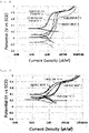
- FIG. 3 is a graph showing potentiodynamic corrosion resistance measurement results of the samples manufactured according to Comparative Examples 1 through 3 and 5, and FIG. 4 is a graph showing potentiodynamic corrosion resistance measurement results of the samples manufactured according to Embodiments 1 through 4.
- FIG. 5 shows pictures of contact angles of the samples manufactured according to Comparative Examples 1 through 3 and 5
- FIG. 6 shows pictures of contact angles of the samples manufactured according to Embodiments 1 through 4.
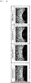
- FIG. 7 shows pictures indicating whether a corrosion product (smut) remains for samples manufactured according to Embodiments 3 and 5 and Comparative Example 3.
- FIG. 8 is a graph showing XPS analysis results of the samples manufactured according to Embodiments 1 and 3 and Comparative Example 1
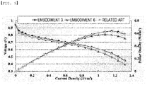
- FIG. 9 is a graph showing results of evaluating stack performance of unit cells using the samples manufactured according to Embodiments 3 and 6 and Comparative Example 2.
- X presence of pitting of 1 ⁇ m or more after surface modification
- O absence of pitting and erosion on the surface
- corrosion resistance may be degraded in a fuel cell operating environment, such that whether erosion and pitting occur after surface modification is important.
- Tafel slope evaluation of a potentiostat is used, and corrosion current upon application of a voltage of 0.6V is measured by performing potentiodynamic evaluation in a mixed solution, heated to 80 °C, of 0.1 N of sulfuric acid and 2 ppm of hydrofluoric acid.
- a contact angle equipment of a model DM700 of Japan's KYOWA company is used, and the contact angle is measured after distilled water of 3 ⁇ l is dropped on the surfaces of the samples.
- water discharge is reduced due to the flooding phenomenon caused by water condensed on the surface of the separator under the fuel cell operating environment, such that the non-uniform flow of the reactive gas and degradation of diffusion of the reactive gas cause a deficiency of the reactive gas in the electrode, deteriorating the performance of the fuel cell, and therefore, it is important to implement a hydrophilic surface having a low contact angle.
- a thickness of a sample is measured before and after surface modification by using a micrometer.
- an engaging pressure of about 1000 stacked separators or more is lowered, degrading the performance of a fuel cell, such that it is important to implement stable surface modification without thickness reduction.
- separator/GDL/MEA/GDL/separator are stacked in that order to form a unit cell.
- separator the related art and Embodiments 3 and 6 are used, and performance comparison is performed in the same cell.
- the samples according to Embodiments 1 through 6 obtain clean surfaces without foreign substances thereon, obtain stable surfaces without pitting occurring thereon, and obtain stable surfaces without erosion occurring thereon (without thickness change).
- the samples according to Embodiments 1 through 6 obtain an interfacial contact resistance of 20 m ⁇ cm 2 or less under a pressure of 1.0 MPa and show a corrosion current of 15 ⁇ A(SCE) or less at a voltage of 0.6V in a solution, heated to 60 °C, of 0.1 N of sulfuric acid and 2 ppm of hydrofluoric acid, simulating a harsh operating environment of the polymer fuel cell.
- stainless steel for a fuel cell separator may be manufactured through wet surface modification, which satisfies interfacial contact resistance, corrosion resistance, and contact angle characteristics required in the polymer fuel cell, and it is observed that corrosion resistance is improved through further thermal processing.
- Embodiment 2 due to an inefficient processing time in a continuous manufacturing process, a processing time needs to be improved.
- Embodiment 3 and Embodiment 4 a processing temperature is increased when compared to in Embodiment 2, thereby innovatively reducing a processing time.
- Embodiment 1 Compared with Embodiment 3, it is seen that a content of Cr is reduced by about 15% after wet surface processing, and it is thought that iron is oxidized in thermal processing and thus a composition ratio on the surface is increased. In this way, it is determined that in a process of removing and reconstructing an oxide layer, which is a factor hindering an interfacial contact resistance, from the surface, using the method proposed in the present disclosure, the surface is modified, thus improving a contact resistance.
Landscapes
- Chemical & Material Sciences (AREA)
- Engineering & Computer Science (AREA)
- Materials Engineering (AREA)
- Mechanical Engineering (AREA)
- Metallurgy (AREA)
- Organic Chemistry (AREA)
- General Chemical & Material Sciences (AREA)
- Chemical Kinetics & Catalysis (AREA)
- Manufacturing & Machinery (AREA)
- Sustainable Development (AREA)
- Sustainable Energy (AREA)
- Electrochemistry (AREA)
- Life Sciences & Earth Sciences (AREA)
- Composite Materials (AREA)
- Fuel Cell (AREA)
- Chemical Treatment Of Metals (AREA)
- ing And Chemical Polishing (AREA)
Abstract
Description
- The present disclosure relates to stainless steel for a polymer fuel cell separator used in an electricity generator using a hydrogen fuel, and a method of manufacturing the stainless steel, and more particularly, to stainless steel for a polymer fuel cell separator and a method of manufacturing the stainless steel, in which a surface modification technique based on wet processing is applied to a surface of stainless steel used for an anode, a cathode, etc., of a stack that generates electricity, thus providing corrosion resistance and electrical conductivity and preventing moisture from being formed.
- The present disclosure also relates to stainless steel for a polymer fuel cell separator and a method of manufacturing the stainless steel, in which durability is superior with electrical, chemical, and physical stability by using a surface modification technique based on a chemical method instead of a coating method or a passivation processing method.
- A hydrogen fuel cell is an eco-friendly electricity generator that generates water and electrical energy by using hydrogen and oxygen in the atmosphere, reversely to a method of generating hydrogen and oxygen based on water electrolysis with an eco-friendly electric power generation system that has emerged as a scheme to replace a fossil fuel and reduce air pollution. Among fuel cells, especially, a polymer fuel cell (a proton exchange membrane fuel cell: PEMFC) has advantages such as a low operating temperature of 60 to 80 °C, a high energy efficiency, etc.
- The polymer fuel cell includes a polymer electrolyte membrane, an electrode, a gas diffusion layer (GDL), and a separator. The separator used in the polymer fuel cell has a structure having formed therein a channel through which hydrogen and oxygen may flow, and separates each unit cell, serves as a support of a membrane electrode assembly (MEA), provides a path through which hydrogen and oxygen may flow, and plays an important role as a current collector that delivers generated energy.
- In the polymer fuel cell (PEMFC) generating electricity by using a hydrogen fuel, hydrogen supplied from a fuel electrode (an anode) is dissociated into hydrogen ions and electrons while passing through an electrolyte layer, and the hydrogen ions move to an air electrode (a cathode) and react with oxygen to form water, and the electrons move from the electrolyte layer to an electricity storage device (a battery) through an external circuit to form electricity, such that electricity is produced based on an electrochemical reaction between hydrogen and oxygen.
- The polymer fuel cell includes a polymer electrolyte membrane, an electrode, a GDL, and a separator. The separator used in the polymer fuel cell has a structure having formed therein a channel through which hydrogen and oxygen may flow, and separates each unit cell, serves as a support of a membrane electrode assembly (MEA), provides a path through which hydrogen and oxygen may flow, and plays an important role of a current collector that delivers generated energy.
- A fuel cell separator, which refers to a fuel electrode (an anode) and an air electrode (a cathode), enables an electrochemical reaction between hydrogen and oxygen. Thus, the fuel cell separator requires superior electrical conductivity to facilitate movement of electrons and needs to guarantee corrosion resistance to prevent corrosion in a reaction between the anode and the cathode. To prevent moisture condensation (a flooding phenomenon) by lowering a surface tension for smoothly discharging water generated by an electrochemical reaction between hydrogen and oxygen, excellent hydrophilicity is required.
- The fuel cell separator requires superior thermal and electrical conductivity, a mechanical strength for preventing deformation and avoiding destruction due to vibration or shocks, dimensional stability, chemical resistance, etc., and graphite, a Ti alloy, conductive plastic, stainless steel, etc., have such properties, and as a metal electrode plate, stainless steel is used for excellent thermal conductivity, formability, dimensional stability, and corrosion resistance, and conductivity is given to the electrode plate by coating the electrode plate or forming a conductive film on the electrode plate.
- A carbon (or graphite) -based separator has a high gas or liquid permeability and poor mechanical strength and moldability, and has a high processing cost. On the other hand, a stainless metal separator has superior gas tightness and high thermal and electrical conductivity, and is able to be thinned, guaranteeing lightweightness and excellent shock resistance. Moreover, the stainless metal separator has the advantage of reducing the price of the separator with excellent production yield in application of a thin plate forming process such as stamping, hydroforming, etc.
- With this advantage, a demand for using stainless steel as a polymer fuel cell separator has been increasing recently. Stainless steel has an excellent thinning property and formability, but has a high contact resistance due to a Cr2O3 passivation film formed on a surface of the stainless steel, resulting in low electrical conductivity.
- To solve this problem, after a separator is manufactured by forming a flow path in stainless steel, a conductive material, such as Au, Pt, C, etc., is coated onto a surface of the fuel cell separator to give conductivity in a final process, thereby improving electrical conductivity.
- However, a process of coating the conductive material such as Au, Pt, C, etc., occupies a high proportion of a manufacturing cost of the fuel cell separator, such that this issue needs to be solved to improve production cost and yield.
- Stainless steel is made of an alloy including iron and chromium or including iron, chromium, and nickel, and the corrosion resistance of the stainless steel may be excellent by forming a very thin chrome oxide layer (Cr2O3) in which chromium (Cr) is combined with the surface of the steel to block intrusion of oxygen into a metal matrix. As the chrome oxide layer (Cr2O3) formed on the surface of stainless steel is formed firmly, corrosion resistance may be superior, but as the firm oxide layer is formed, electrical conductivity may be degraded.
- With such properties, for the separator, a method of coating or carbon coating using gold or white gold, which is precious metal with excellent corrosion resistance and electrical conductivity, and a method of forming a conductive film after stainless passivation are applied.
- A related prior document,
Korean Patent Publication Gazette No. 10-2015-0074768 (published on July 02, 2015 - The present disclosure provides stainless steel for a polymer fuel cell separator and a method of manufacturing the stainless steel, in which a chemical surface modification technique, instead of coating or conductive film formation, is applied to simultaneously implement corrosion resistance and electrical conductivity that are mechanical properties for use as a fuel cell separator, thereby securing a superior interfacial contact resistance.
- The present disclosure also provides stainless steel for a polymer fuel cell separator and a method of manufacturing the stainless steel, in which a thermal oxide film generated in a steel making and rolling process or a natural oxide film formed in an atmosphere environment are removed by etching and a chemical surface modification technique is applied, such that the stainless steel has a contact resistance of 10 to 35 mΩ·cm2 under a pressure of 1.0 MPa, and has a contact angle of 30° ~ 70° in a contact angle (water droplet formation) test to provide a high-temperature potentiodynamic corrosion resistance of 15 µA/cm2 or less and remove moisture condensation in a mixed solution of sulfuric acid of 0.1 N and hydrofluoric acid of 2 ppm at a temperature of 80 °C that is a polymer fuel cell environment temperature.
- According to an aspect of the present disclosure, stainless steel for a polymer fuel cell separator includes, by weight%, C: 0.01 ~ 0.08%, Si: 0.3 ~ 1.0%, Mn: 0.3 ~ 2.0%, Cr: 15 ~ 35%, Cu: 1.0% or less, N: 0.01 ~ 0.05%, Ti: 0.3% or less, Nb: 0.3% or less, and as the rest, Fe and other inevitable impurities, and a surface modification layer having an interfacial contact resistance of 10 ~ 35 mΩ·cm2 through surface modification processing, in which a potentiodynamic corrosion resistance is 1.0 ~ 15.0 µA/cm2 and a contact angle is 30 ~ 70°.
- The stainless steel may further include one or more kinds of P: 0.14 weight% or less, S: 0.03 weight% or less, H: 0.004 weight% or less, and O: 0.007 weight% or less.
- The surface modification processing may include degreasing processing of performing immersion in a degreasing solution, etching and desmut processing of performing etching with an etching solution and desmut processing in a desmut solution, and surface stabilization processing of performing immersion in a surface stabilization solution.
- According to another aspect of the present disclosure, a method of manufacturing stainless steel for a polymer fuel cell separator includes, (a) providing a stainless base material including, by weight%, C: 0.01 ~ 0.08%, Si: 0.3 ~ 1.0%, Mn: 0.3 ~ 2.0%, Cr: 15 ~ 35%, Cu: 1.0% or less, Ni: 10 ~ 25%, N: 0.01 ~ 0.05%, Ti: 0.3% or less, Nb: 0.3% or less, and as the rest, Fe and other inevitable impurities, the stainless base material having a passivation film formed on a surface thereof, (b) performing degreasing processing by immersing the surface of the stainless base material in a degreasing solution, (c) after etching the degreasing-processed stainless base material with an etching solution, performing desmut processing with a desmut solution, and (d) performing surface stabilization on the etched and desmut-processed stainless base material with a surface stabilization solution, in which after (d), the stainless steel includes a surface modification layer having an interfacial contact resistance of 10 ~ 35 mΩ·cm2, through surface modification processing.
- The stainless base material may further include one or more kinds of P: 0.14 weight% or less, S: 0.03 weight% or less, H: 0.004 weight% or less, and O: 0.007 weight% or less.
- In (b), the degreasing processing may include performing immersion in the degreasing solution at 30 ~ 70°C for 0.5 ~ 5 minutes.
- In (c), the etching processing may include performing immersion for 0.2 ~ 2 minutes in an etching solution, heated to 40 ~ 80°C, including at least two or more of 2.5 ~ 6.2 mols of sulfate ions, 0.1 ~ 2.0 mols of nitrate ions, and 1.0 ~ 5.0 mols of fluorine, and the desmut processing may include performing immersion for 0.5 ~ 2 minutes in a desmut solution, heated to 40 ~ 80°C, including 1.5 ~ 6.0 mols of hydrogen peroxide, 1.0 ~ 4.0 mols of fluorine, and 0.001 ~ 0.01 mol of a corrosion inhibitor.
- After (d), the method may further include (e) performing stabilization thermal processing for stabilization of the surface-stabilized stainless base material.
- The stabilization thermal processing may be performed at 150 ~ 250°C for 1 ~ 10 minutes.
- Stainless steel for a polymer fuel cell separator and a method of manufacturing the stainless steel according to the present disclosure modify a surface passivation film without corrosion or pitting with respect to a stainless base material having a passivation film on a surface thereof, thereby securing a low interfacial contact resistance, superior corrosion resistance, and excellent wettability.
- Moreover, the stainless steel for a polymer fuel cell separator and the method of manufacturing the stainless steel according to the present disclosure may provide a superior interfacial contact resistance and corrosion resistance without additional coating of precious metal or conductive materials, and provide excellent surface wettability without further hydrophilic processing or coating.
-
-
FIG. 1 is a flowchart illustrating a method of manufacturing stainless steel for a polymer fuel cell separator, according to an embodiment of the present disclosure. -
FIG. 2 is a schematic diagram for describing a process of measuring interfacial contact resistances of samples according toEmbodiments 1 through 6 and Comparative Examples 1 through 9. -
FIG. 3 is a graph showing potentiodynamic corrosion resistance measurement results with respect to samples manufactured according to Comparative Examples 1 through 3 and 5. -
FIG. 4 is a graph showing potentiodynamic corrosion resistance measurement results with respect to samples manufactured according toEmbodiments 1 through 4. -
FIG. 5 shows pictures of contact angles of samples manufactured according to Comparative Examples 1 through 3 and 5. -
FIG. 6 shows pictures of contact angles of samples manufactured according to Embodiments 1 through 4. -
FIG. 7 shows pictures indicating whether a corrosion product (smut) remains for samples manufactured according to Embodiments 3 and 5 and Comparative Example 3. -
FIG. 8 is a graph showing X-ray photoelectron spectroscopy (XPS) analysis results with respect to samples manufactured according toEmbodiments -
FIG. 9 is a graph showing stack performance measurement results with respect to a unit cell using samples manufactured according toEmbodiments - Advantages and features of the present disclosure and a method for achieving them will be apparent with reference to embodiments described in detail, together with the attached drawings. However, the present disclosure is not limited to the disclosed embodiments, but may be implemented in various manners, the embodiments are provided to complete the disclosure of the present disclosure and to allow those of ordinary skill in the art to understand the category of the present disclosure, and the present disclosure is defined by the category of the claims. Throughout the specification, an identical reference numeral will indicate an identical component.
- Hereinafter, with reference to the accompanying drawings, stainless steel for a polymer fuel cell separator and a method of manufacturing the stainless steel according to an embodiment of the present disclosure will be described in detail.
- Stainless steel for a polymer fuel cell separator according to an embodiment of the present disclosure may include, by weight%, C: 0.01 ~ 0.08%, Si: 0.3 ~ 1.0%, Mn: 0.3 ~ 2.0%, Cr: 15 ~ 35%, Cu: 1.0% or less, N: 0.01 ~ 0.05%, Ti: 0.3% or less, Nb: 0.3% or less, and as the rest, Fe and other inevitable impurities, and may include a surface modification layer having an interfacial contact resistance of 10 ~ 35 mΩ·cm2 under a pressure of 1.0 MPa through surface modification processing.
- The stainless steel for the polymer fuel cell separator according to an embodiment of the present disclosure may further include one or more kinds of P: 0.14 weight% or less, S: 0.03 weight% or less, H: 0.004 weight% or less, and O: 0.007 weight% or less.
- As a result, the stainless steel for the polymer fuel cell separator according to an embodiment of the present disclosure may have a potentiodynamic corrosion resistance of 15 µA/cm2 or less (sulfuric acid of 0.1 N and hydrofluoric acid of 2 ppm at 80 °C, SCE), more preferably, 1.0 ~ 15.0 µA/cm2, and a contact angle of 70° or less, more preferably, a contact angle range of 30° ~ 70°, when a droplet of 3 µl is dropped.
- Hereinbelow, a role and a content of each component included in the stainless steel for the polymer fuel cell separator according to an embodiment of the present disclosure will be described.
- Carbon (C) is an essential element for increasing the strength of austenitic stainless steel, and may be preferably added at a content ratio of 0.01 ~ 0.08 weight% to a total weight. When the amount of addition of carbon (C) is less than 0.01 weight%, a refining price for making a high-purity product may increase. In contrast, when the amount of addition of carbon (C) exceeds 0.08 weight%, processability and toughness may be degraded due to increase of impurities.
- Silicon (Si) is an effective element for deoxidation, and may be preferably added at a content ratio of 0.3 ~ 1.0 weight% to a total weight. When the amount of addition of silicon (Si) is less than 0.3 weight%, a refining price may be increased. On the other hand, when the amount of addition of silicon (Si) exceeds 1.0 weight%, a material may be hardened, degrading toughness and thus formability.
- Manganese (Mn) is an essential element for increasing austenitic phase stability, and may be preferably added at a content ratio of 0.3 ~ 2.0 weight% to a total weight. When the amount of addition of manganese (Mn) is less than 0.3 weight%, a target physical property may be difficult to secure. In contrast, when the amount of addition of manganese (Mn) exceeds 2.0 weight%, corrosion resistance may be degraded due to excessive addition of manganese (Mn).
- Chromium (Cr) is an essential element for improving corrosion resistance and oxidation resistance in an operating environment of a fuel cell, and may be preferably added at a content ratio of 15 ~ 35 weight% to a total weight. When the amount of addition of chromium (Cr) is less than 15 weight%, it is difficult to secure proper oxidation resistance in the operating environment of the fuel cell. In contrast, when the amount of addition of chromium (Cr) exceeds 35 weight%, a manufacturing cost may be increased and toughness may be degraded, due to addition more than necessary.
- Copper (Cu) is an economical additive element that may substitute for expensive molybdenum (Mo) to increase pitting resistance in an acidic atmosphere where the fuel cell operates. However, when Cu is excessively added, the performance of the fuel cell may be degraded due to elution of Cu, and thus in consideration of this, in the present disclosure, Cu is limited to 1.0 weight% or less to the total weight of the stainless steel.
- Nitrogen (N), which is an element for forming a nitride, exists interstitially, such that when N is contained excessively, it may be an unfavorable to elongation rate and yield point elongation in spite of increase of strength. Thus, in the present disclosure, nitrogen may be preferably limited to a content ratio of 0.01 ~ 0.05 weight% to the total weight of the stainless steel.
- Titanium (Ti) is an effective element for forming C and N of the steel into a carbonitride, but may degrade toughness when added excessively. Thus, in the present disclosure, in consideration of this, Ti is limited to 0.3 weight% or less to the total weight of the stainless steel.
- Niobium (Nb), like titanium, is an effective element for forming C and N of the steel into a carbonitride, but may degrade toughness when added excessively. Thus, in the present disclosure, in consideration of this, Ti is limited to 0.3 weight% or less to the total weight of the stainless steel.
- Phosphorus (P) reduces toughness as well as corrosion resistance, and thus in the present disclosure, is limited to 0.14 weight% or less to the total weight of the stainless steel.
- Sulfur (S) may form manganese sulfide (MnS) that becomes a starting point of corrosion and thus reduces corrosion resistance, and thus in the present disclosure, in consideration of this, S is limited to 0.03 weight% to the total weight of the stainless steel.
- Hydrogen (H) and oxygen (O), which are inevitably added impurities, may be preferably limited strictly to 0.004 weight% or less and 0.007 weight% or less, respectively, to the total weight of the stainless steel of the present disclosure.
- Hereinafter, with reference to the accompanying drawings, a method of manufacturing the stainless steel for the polymer fuel cell separator according to an embodiment of the present disclosure will be described.
-
FIG. 1 is a flowchart illustrating a method of manufacturing stainless steel for a polymer fuel cell separator, according to an embodiment of the present disclosure. - As illustrated in
FIG. 1 , a method of manufacturing stainless steel for a polymer fuel cell separator, according to an embodiment of the present disclosure, may include stainless base material providing operation S110, degreasing processing operation S120, etching and desmut processing operation S130, and surface stabilization processing operation S140. The method of manufacturing stainless steel for a polymer fuel cell separator according to an embodiment of the present disclosure may further include stabilization thermal-processing operation S150. The stabilization thermal-processing operation S150 may not be necessarily performed and may be omitted depending on needs. - In operation S110 of providing the stainless base material, the stainless base material is provided which includes, by weight%, C: 0.01 ~ 0.08%, Si: 0.3 ~ 1.0%, Mn: 0.3 ~ 2.0%, Cr: 15 ~ 35%, Cu: 1.0% or less, N: 0.01 ~ 0.05%, Ti: 0.3% or less, Nb: 0.3% or less, and as the reset, Fe and other inevitable impurities, and has a passivation film formed on a surface thereof.
- The stainless base material may further include one or more kinds of P: 0.14 weight% or less, S: 0.03 weight% or less, H: 0.004 weight% or less, and O: 0.007 weight% or less.
- In this case, the passivation film may cover the surface of the stainless base material. The passivation film may include Cr2O3. The passivation film may be formed on a top surface or a bottom surface of the stainless base material or both the top surface and the bottom surface.
- In this case, the stainless base material has an excellent thinning property and formability, but has a high electrical resistance due to the Cr2O3 passivation film formed on the surface thereof, resulting in low electrical conductivity.
- Generally, the stainless base material may have, but not limited to, a thickness of 0.05 ~ 10 mm. The stainless base material may have a high contact resistance of 200 ~ 500 mΩ·cm2 under a pressure of 1.0 MPa due to the Cr2O3 passivation film generated on the surface thereof. Therefore, to use the stainless base material as the fuel cell separator, low contact resistance needs to be secured.
- In degreasing processing operation S120, the surface of the stainless base material may be degreased by being immersed in a degreasing solution.
- Herein, the degreasing processing may be performed to remove an organic matter such as the Cr2O3 passivation film attached onto the surface of the stainless base material, etc. There is no significant distinction between an acidic solution, a neutral solution, or an alkaline solution in the degreasing processing, and any solution capable of removing an organic matter adsorbed in the rolling process of the stainless base material may be used limitlessly.
- More preferably, the degreasing solution may include 0.1 ~ 3 mols of one or more kinds of sodium hydroxide and potassium hydroxide, 0.01 ~ 2 mols of silicate, 0.005 ~ 0.8 mol of phosphate, 0.02 ~ 3 mols of carbonate, a surfactant, and an emulsifier.
- In this operation, the degreasing processing may preferably include immersion processing in the degreasing solution at 30 ~ 70 °C for 0.5 ~ 5 minutes. When a degreasing processing temperature is lower than 30 °C or a degreasing processing time is shorter than 0.5 minute, there is a high risk of failing to completely remove the organic matter existing on the surface of the stainless base material. On the other hand, when the degreasing processing temperature is higher than 70 °C or the degreasing processing time is longer than 5 minutes, the degreasing processing may become a factor that increases a manufacturing cost without further effect increase, resulting in diseconomy.
- In etching and desmut processing operation S130, after the degreasing-processed stainless base material is etched with an etching solution, desmut processing may be performed with a desmut solution.
- When etching processing is applied to remove heat and a natural oxide film existing on the surface of the stainless base material, a smut that is a corrosion product may be generated excessively, and in this case, stains and discoloration may occur in the exterior, adversely affecting a contact resistance, corrosion resistance, and a contact angle. Thus, etching processing needs to be accompanied by desmut processing.
- Due to the heat and the natural oxide film existing on the surface of the stainless base material, the interfacial contact resistance is equal to or greater than 300 mΩ·cm2 under a pressure of 1.0 MPa, and the contact angle is 75° ~ 100° with a hydrophobic property.
- In this operation, etching processing may preferably include immersion for 0.2 ~ 2 minutes in an etching solution, heated to 40 ~ 80°C, including at least two or more of 2.5 ~ 6.2 mols of sulfate ions, 0.1 ~ 2.0 mols of nitrate ions, and 1.0 ~ 5.0 mols of fluorine.
- Desmut processing may preferably include immersion for 0.5 ~ 2 minutes in a desmut solution, heated to 40 ~ 80°C, including 1.5 ~ 6.0 mols of hydrogen peroxide, 1.0 ~ 4.0 mols of fluorine, and 0.001 ~ 0.01 mol of a corrosion inhibitor. Herein, as the corrosion inhibitor, benzotriazole may be used, without being limited thereto.
- In this operation, when a thickness of 0.2 ~ 5 µm is etched, an oxide film existing on the surface of the stainless base material may be completely removed and a hydrophilic property of a contact angle of 30° ~ 70° and a contact resistance of 10 ~ 35 mΩ·cm2 may be given. At a high concentration and a high temperature of about 80 °C, more etching may be made; at a low concertation or a low temperature, the oxide film may not be removed, such that the contact resistance may exceed 30 mΩ·cm2.
- As such, when an excessive reaction occurs due to a processing condition, a thickness of a product may significantly decrease due to an excessive etching amount, failing to have characteristics as the fuel cell separator.
- In surface stabilization processing operation S140, the etched and desmut-processed stainless base material is subject to surface stabilization processing with a surface stabilization solution.
- The surface stabilization processing may be performed by immersing the etched and desmut-processed stainless base material at 50 ~ 80°C for 0.5 ~ 5 minutes, in the surface stabilization solution including 2.7 ~ 13.8 mols of nitrate, 0.05 ~ 0.5 mol of sulfate, a surfactant, and a stabilizer. Generally, in the case of well-known passivation processing, the oxide film may be densely formed, improving corrosion resistance, but increasing a contact resistance, and when the oxide film is thin and porous, corrosion resistance may become weak in spite of a low contact resistance.
- On the other hand, when the surface stabilization processing is performed like in the present disclosure, a surface modification layer of a thickness of several ~ several tens of nanometers (nm) may be formed on the surface of the stainless base material, thereby giving superior corrosion resistance while maintaining a low contact resistance.
- Through such surface stabilization processing, i.e., surface modification processing, stainless steel according to the present disclosure may have a surface modification layer having an interfacial contact resistance of 10 ~ 35 mΩ·cm2 under a pressure of 1.0 MPa.
- In stabilization thermal processing operation S150, stabilization thermal processing may be performed to stabilize the surface-stabilized stainless base material.
- Such stabilization thermal processing may be carried out to remove moisture remaining on the surface of the stainless base material after the surface stabilization processing and promote stabilization of the surface modification layer.
- To this end, the stabilization thermal processing may be preferably performed for 1 ~ 10 minutes in an atmospheric condition of 150 ~ 250 °C. The surface modification layer formed by wet surface processing has a shelf life due to a continuous reaction with oxygen in the atmospheric environment, and to reduce surface property change with the shelf life in the formation of the oxide layer, the activated surface modification layer is stabilized by thermal processing. Thus, at an environment temperature of 80 °C required in the fuel cell, a high-temperature potentiodynamic corrosion resistance of 15 µA/cm2(SCE) or less may be guaranteed.
- The surface of the stainless steel for the polymer fuel cell separator manufactured through the foregoing process (S110 through S150) is modified by reconstructing the passivation film through surface modification processing, thereby securing superior interfacial contact resistance without being coated with a conductive material.
- As such, in the present disclosure, by performing modification processing of removing and reconstructing the passivation film on the surface of the stainless base material, a low interfacial contact resistance, superior potentiodynamic corrosion resistance, and excellent surface wettability for use as the fuel cell separator may be guaranteed.
- As a result, the stainless steel for the polymer fuel cell separator according to an embodiment of the present disclosure has an interfacial contact resistance of 35 mΩ·cm2 or less under a pressure of 1.0 MPa without coating with a conductive material, thereby satisfying properties required for the polymer fuel cell separator.
- Hereinbelow, the structure and action of the present disclosure will be described in more detail with reference to an embodiment of the present disclosure. However, this will be provided as a preferred example of the present disclosure, and is not interpreted as limiting the present disclosure in any sense.
- A matter not described herein may be sufficiently technically construed by those of ordinary skill in the art and thus will not be described.
- A stainless base material including, by weight%, C: 0.05%, Si: 0.6%, Mn: 1.1%, Cr: 21%, Cu: 0.4%, N: 0.03%, Ti: 0.2%, Nb: 0.1%, and Fe as the rest, and having a passivation film formed thereon is provided, and is measured without separate surface processing after alkaline degreasing.
- Au is coated on the stainless base material manufactured according to Comparative Example 1 to a thickness of 1 µm to manufacture a sample.
- Surface modification of immersing the stainless base material manufactured according to Comparative Example 1 in a complex mixed solution, heated to 30 °C, of 4.7 mols of sulfuric acid, 1.1 mol of nitric acid, and 2.1 mols of fluorine (F-) for 60 secs is performed to manufacture a sample.
- After etching of immersing the stainless base material manufactured according to Comparative Example 1 in a complex mixed solution, heated to 30 °C, of 4.7 mols of sulfuric acid, 1.1 mols of nitric acid, and 2.1 mols of fluorine (F-), for 60 secs, desmut processing of immersion in a mixed solution, heated to 30 °C, of 3.4 mols of hydrogen peroxide and 2.1 mols of fluorine (F-) for 60 secs is performed to manufacture a sample.
- Except for immersion at an etching temperature of 60 °C, a sample is manufactured in the same manner as in Comparative Example 4.
- After etching of immersing the stainless base material manufactured according to Comparative Example 1 in a complex mixed solution, heated to 60 °C, of 2.5 mols of sulfuric acid and 4.1 mols of fluorine (F-), for 60 secs, desmut processing of immersion in a mixed solution, heated to 60 °C, of 3.4 mols of hydrogen peroxide and 2.1 mols of fluorine (F-) for 60 secs is performed to manufacture a sample.
- After the same processing as Comparative Example 6, immersion in a mixed solution, heated to 60 °C, of 0.5 mol of sulfuric acid and 10.4 mols of nitric acid for 100 secs is performed to manufacture a sample.
- Except for immersion in a complex mixed solution, heated to 60 °C, of 4.7 mols of sulfuric acid, 1.1 mols of nitric acid, and 2.1 mols of fluorine (F-), for 150 secs, a sample is manufactured in the same process as Comparative Example 7 after etching.
- Except for immersion in a complex mixed solution, heated to 60 °C, of 6.2 mols of sulfuric acid, 1.1 mols of nitric acid, and 2.1 mols of fluorine (F-), for 150 secs, a sample is manufactured in the same process as Comparative Example 7 after etching.
- A stainless base material including, by weight%, C: 0.05%, Si: 0.6%, Mn: 1.1%, Cr: 21%, Cu: 0.4%, N: 0.03%, Ti: 0.2%, Nb: 0.1%, and as the rest, Fe, and having a passivation film formed thereon is provided and alkaline degreasing is performed to remove an organic matter from the surface.
- Next, after etching is performed for 60 secs through immersion in a complex mixed solution, heated to 60 °C, of 4.7 mols of sulfuric acid, 1.1 mols of nitric acid, and 2.1 mols of fluorine (F-), desmutting is performed for 60 secs in a mixed solution, heated to 60 °C, of 3.4 mols of hydrogen peroxide and 2.1 mols of fluorine (F-), after which immersion in a mixed solution, heated to 60 °C, of 0.5 mol sulfuric acid and 11.4 mols nitric acid for 100 secs is performed to manufacture a sample.
- A sample manufactured in the same manner as
Embodiment 1 undergoes stabilization thermal processing at a temperature of 100 °C for 600 secs to manufacture a sample. - A sample manufactured in the same manner as
Embodiment 1 undergoes stabilization thermal processing at a temperature of 200 °C for 120 secs to manufacture a sample. - A sample manufactured in the same manner as
Embodiment 1 is subject to stabilization thermal processing at a temperature of 200 °C for 300 secs to manufacture a sample. - Except for immersion in a complex mixed solution, heated to 60 °C, of 6.2 mols of sulfuric acid, 1.1 mols of nitric acid, and 2.1 mols of fluorine (F-) and etching for 60 secs in the etching process, a sample is manufactured in the same manner as
Embodiment 1. - A sample manufactured in the same manner as
Embodiment 5 is subject to stabilization thermal processing for 120 secs at 200 °C to manufacture a sample. - Table 1 shows processing conditions for manufacturing samples according to
Embodiments 1 through 6 and Comparative Examples 1 through 9, and Table 2 shows physical property evaluation results of the samples manufactured according toEmbodiments 1 through 6 and Comparative Examples 1 through 9. -
FIG. 2 is a schematic diagram for describing a process of measuring interfacial contact resistances of the samples according toEmbodiments 1 through 6 and Comparative Examples 1 through 9. -
FIG. 3 is a graph showing potentiodynamic corrosion resistance measurement results of the samples manufactured according to Comparative Examples 1 through 3 and 5, andFIG. 4 is a graph showing potentiodynamic corrosion resistance measurement results of the samples manufactured according toEmbodiments 1 through 4. -
FIG. 5 shows pictures of contact angles of the samples manufactured according to Comparative Examples 1 through 3 and 5, andFIG. 6 shows pictures of contact angles of the samples manufactured according toEmbodiments 1 through 4. -
FIG. 7 shows pictures indicating whether a corrosion product (smut) remains for samples manufactured according toEmbodiments -
FIG. 8 is a graph showing XPS analysis results of the samples manufactured according toEmbodiments FIG. 9 is a graph showing results of evaluating stack performance of unit cells using the samples manufactured according toEmbodiments - Surface cleanliness is observed by naked eyes, and in the case of discoloration due to residual corrosion products on the surface and emergence of foreign substances when wiped with a cotton swab, etc., such presence is indicated by X, and absence is indicated by O.
- As a criterion for evaluating official stability, presence of pitting of 1 µm or more after surface modification is indicated by X and absence of pitting and erosion on the surface is indicated by O. Herein, when erosion and pitting occur on a stainless steel sample after surface modification, corrosion resistance may be degraded in a fuel cell operating environment, such that whether erosion and pitting occur after surface modification is important.
- As shown in
FIG. 2 , by using a method of measuring current under a pressure of 1.0 MPa after insertion of stainless steel (sample) between gas diffusion layers (GDLs), a contact resistance after surface modification is measured. - For corrosion current, Tafel slope evaluation of a potentiostat is used, and corrosion current upon application of a voltage of 0.6V is measured by performing potentiodynamic evaluation in a mixed solution, heated to 80 °C, of 0.1 N of sulfuric acid and 2 ppm of hydrofluoric acid.
- For a contact angle, equipment of a model DM700 of Japan's KYOWA company is used, and the contact angle is measured after distilled water of 3 µl is dropped on the surfaces of the samples. Herein, when the contact angle on the surface of the stainless steel is high after surface modification, water discharge is reduced due to the flooding phenomenon caused by water condensed on the surface of the separator under the fuel cell operating environment, such that the non-uniform flow of the reactive gas and degradation of diffusion of the reactive gas cause a deficiency of the reactive gas in the electrode, deteriorating the performance of the fuel cell, and therefore, it is important to implement a hydrophilic surface having a low contact angle.
- For thickness reduction after surface modification, a thickness of a sample is measured before and after surface modification by using a micrometer. When a thickness of a material is reduced due to an excessive etching reaction, an engaging pressure of about 1000 stacked separators or more is lowered, degrading the performance of a fuel cell, such that it is important to implement stable surface modification without thickness reduction.
- For separator performance evaluation, separator/GDL/MEA/GDL/separator are stacked in that order to form a unit cell. As the separator, the related art and Embodiments 3 and 6 are used, and performance comparison is performed in the same cell.
[Table 1] Category Etching Desmut Surface Stabilization Stabilizat ion Thermal Processing sulf uric acid (mol /L) nitr ogen (mol /L) fluo ride (F) (mol /L) time (sec ) temp erat ure (°C) hydr ogen pero xide (mol /L) fluo ride (F) (mol /L) time (sec ) temp erat ure (°C) sulf uric acid (mol /L) nitro gen (mol/ L) time (sec ) temp erat ure (°C) time (sec ) temp erat ure (°C) Compara tive Example 1 - - - - - - - - - - - - - - - Compara tive Example 2 - - - - - - - - - - - - - - - Compara tive Example 3 4.7 1.1 2.1 60 30 - - - - - - - - - Compara tive Example 4 4.7 1.1 2.1 60 30 3.4 2.1 60 30 - - - - - Compara tive Example 5 4.7 1.1 2.1 60 60 3.4 2.1 60 30 - - - - - Compara tive Example 6 2.5 - 4.1 60 60 3.4 2.1 60 60 - - - - - Compara tive Example 7 2.5 - 4.1 60 60 3.4 2.1 60 60 0.5 10.4 100 60 - - Compara tive Example 8 4.7 1.1 2.1 150 60 3.4 2.1 60 60 0.5 11.4 100 60 - - Compara tive Example 9 6.2 1.1 2.1 150 60 3.4 2.1 60 60 0.5 11.4 100 60 - - Embodim ent 1 4.7 1.1 2.1 60 60 3.4 2.1 60 60 0.5 11.4 100 60 - - Embodim ent 2 4.7 1.1 2.1 60 60 3.4 2.1 60 60 0.5 11.4 100 60 600 100 Embodim ent 3 4.7 1.1 2.1 60 60 3.4 2.1 60 60 0.5 11.4 100 60 120 200 Embodim ent 4 4.7 1.1 2.1 60 60 3.4 2.1 60 60 0.5 11.4 100 60 300 200 Embodim ent 5 6.2 1.1 2.1 60 60 3.4 2.1 60 60 0.5 11.4 100 60 - - Embodim ent 6 6.2 1.1 2.1 60 60 3.4 2.1 60 60 0.5 11.4 100 60 120 200 [Table 2] Category Surface Cleanliness Pitting Stability Contact Resistance (mΩ·cm2) Corrosion Current (µA/cm2) Contact Angle (°) Thickness Reduction (µm) Comparative Example 1 ○ ○ 400 7 82 - Comparative Example 2 ○ ○ 15 1 76 - Comparative Example 3 X ○ 250 25 125 - Comparative Example 4 X ○ 35 30 80 - Comparative Example 5 X ○ 25 19 118 - Comparative Example 6 ○ X 23 17 75 - Comparative Example 7 ○ X 24 10 75 - Comparative Example 8 ○ ○ 10 16 30 5 Comparative Example 9 ○ ○ 13 12 23 10 Embodiment 1○ ○ 10 14 19 - Embodiment 2○ ○ 12 10 32 - Embodiment 3○ ○ 12 5 50 - Embodiment 4○ ○ 13 1 55 - Embodiment 5○ ○ 13 12 23 - Embodiment 6○ ○ 19 5 57 - - As shown in Tables 1 and 2 and
FIGS. 2 through 7 , the samples according toEmbodiments 1 through 6 obtain clean surfaces without foreign substances thereon, obtain stable surfaces without pitting occurring thereon, and obtain stable surfaces without erosion occurring thereon (without thickness change). - Moreover, the samples according to
Embodiments 1 through 6 obtain an interfacial contact resistance of 20 mΩ·cm2 or less under a pressure of 1.0 MPa and show a corrosion current of 15 µA(SCE) or less at a voltage of 0.6V in a solution, heated to 60 °C, of 0.1 N of sulfuric acid and 2 ppm of hydrofluoric acid, simulating a harsh operating environment of the polymer fuel cell. - On the other hand, in the case of the sample according to Comparative Example 3, pitting and erosion are not observed, but the sample has the non-uniform etching surface and the corrosion product remaining on the surface, having a bad effect on contact resistance, corrosion current, and contact angle. As shown in
FIG. 5 , on the sample according to Comparative Example 3, the corrosion product remains. - In the case of the sample according to Comparative Example 4, desmut processing for removing the corrosion product generated in the sample according to Comparative Example 3 is performed to improve a contact resistance, but residual foreign substances are not completely removed from the surface.
- In the case of the sample according to Comparative Example 5, as a result of etching processing at a temperature of 60 °C, a lot of corrosion product is generated on the surface in comparison to in the sample according to Comparative Example 4, and the residual foreign substances are not completely removed from the surface in spite of desmut processing.
- For the sample according to Comparative Example 6, pitting occurs on the surface when nitric acid is not added to a complex mixed solution. It is observed that when the nitric acid is added, occurrence of pitting is lowered by induction of a full reaction.
- For the sample according to Comparative Example 7, corrosion resistance is slightly improved by surface stabilization. It is observed that exposure to a nitric acid solution of a high concentration leads to improvement of surface passivation performance.
- For the samples according to Comparative Example 8 and Comparative Example 9, exposure to an etching solution for a long time results in an excessive amount of a corrosion product and thus reduction in the thickness of a material surface on both sides. As the thickness of the material decreases, the engaging pressure of the 1000 stacked separators or more is lowered, degrading fuel cell performance, and desired surface characteristics are not obtained due to excessive etching.
- As in
Embodiment 1 andEmbodiment 2, according to the method proposed in the present disclosure, stainless steel for a fuel cell separator may be manufactured through wet surface modification, which satisfies interfacial contact resistance, corrosion resistance, and contact angle characteristics required in the polymer fuel cell, and it is observed that corrosion resistance is improved through further thermal processing. - However, in
Embodiment 2, due to an inefficient processing time in a continuous manufacturing process, a processing time needs to be improved. - In
Embodiment 3 andEmbodiment 4, a processing temperature is increased when compared to inEmbodiment 2, thereby innovatively reducing a processing time. - However, when the temperature is 300 °C or higher, an excessive oxide layer is formed on the surface, degrading contact resistance characteristics, such that the temperature needs to be controlled below 300°C.
- Comparing
Embodiment 3 withEmbodiment 6, it is observed that an interfacial contact resistance increases after thermal processing when the concentration of sulfuric acid is high in the etching process. It is determined that when the surface unstable due to the excessive amount of etching in the case of exposure to the high sulfuric acid concentration is subject to thermal processing, an oxide layer is generated a lot, increasing contact resistance. - Meanwhile, as shown in
FIG. 8 , by comparing Comparative Example 1 withEmbodiment 1, it is observed that a content of oxygen is reduced by about 15% and a content of chromium is increased by about 15% in a surface top layer after wet surface processing. It is seen from this that as the oxide layer of the surface is removed and the natural oxide film is re-generated in etching processing, a content of a chromium oxide on the surface is increased. - Moreover, by comparing
Embodiment 1 withEmbodiment 3, it is seen that a content of Cr is reduced by about 15% after wet surface processing, and it is thought that iron is oxidized in thermal processing and thus a composition ratio on the surface is increased. In this way, it is determined that in a process of removing and reconstructing an oxide layer, which is a factor hindering an interfacial contact resistance, from the surface, using the method proposed in the present disclosure, the surface is modified, thus improving a contact resistance. - In the foregoing test, in a method of modifying the surface of the stainless steel having a composition range according to the present disclosure, for etching processing in a complex mixed solution of sulfuric acid, nitric acid, and fluorine, desmut processing in a mixed solution of hydrogen peroxide and fluorine, and surface stabilization processing in a mixed solution of sulfuric acid and nitric acid, conditions such as a temperature, composition, etc., of the solution serve as an important factor for implementation of interfacial contact resistance, corrosion resistance, and contact angle characteristics.
- Thus, by modifying the passivation film of the stainless base material, low contact resistance, low corrosion current, and low contact angle may be secured, and by modifying a passivation layer through control of a composition ratio of Cr, Fe, and O elements, stainless steel proper for the polymer fuel cell separator may be produced.
- Meanwhile, as shown in
FIG. 9 , performance evaluation results are shown with respect to unit cells using stainless steel according to the related art (Comparative Example 2) andEmbodiment 3 andEmbodiment 6 according to the present disclosure. - As can be seen from the stack evaluation results of
FIG. 9 , there is little difference in performance between unit cells using the sample according to Comparative Example 2 (the related art) in which Ag is coated on the stainless base material to a thickness of 1 µm and the samples according toEmbodiment 3 andEmbodiment 6 of the present disclosure. - While the embodiments of the present disclosure have been mainly described so far, various changes or modifications can be made at the level of those of ordinary skill in the art. Such changes and modifications can be understood as falling within the present disclosure without departing from the technical spirit of the present disclosure. Accordingly, the scope of the present disclosure should be determined by the appended claims.
-
- S101: Stainless Base Material Providing Operation
- S120: Degreasing Processing Operation
- S130: Etching and Desmut Processing Operation
- S140: Surface Stabilization Processing Operation
- S150: Stabilization Thermal Processing Operation
Claims (9)
- Stainless steel for a polymer fuel cell separator, the stainless steel comprising:by weight%, C: 0.01 ~ 0.08%, Si: 0.3 ~ 1.0%, Mn: 0.3 - 2.0%, Cr: 15 ~ 35%, Cu: 1.0% or less, N: 0.01 ~ 0.05%, Ti: 0.3% or less, Nb: 0.3% or less, Fe, and other inevitable impurities; anda surface modification layer having an interfacial contact resistance of 10 ~ 35 mΩ·cm2 through surface modification processing,wherein a potentiodynamic corrosion resistance is 1.0 ~ 15.0 µA/cm2 and a contact angle is 30 ~ 70°.
- The stainless steel of claim 1, further comprising one or more kinds of P: 0.14 weight% or less, S: 0.03 weight% or less, H: 0.004 weight% or less, and O: 0.007 weight% or less.
- The stainless steel of claim 1, wherein the surface modification processing comprises degreasing processing of performing immersion in a degreasing solution, etching and desmut processing of performing etching with an etching solution and desmut processing in a desmut solution, and surface stabilization processing of performing immersion in a surface stabilization solution.
- A method of manufacturing stainless steel for a polymer fuel cell separator, the method comprising:(a) providing a stainless base material comprising, by weight%, C: 0.01 ~ 0.08%, Si: 0.3 ~ 1.0%, Mn: 0.3 ~ 2.0%, Cr: 15 ~ 35%, Cu: 1.0% or less, Ni: 10 ~ 25%, N: 0.01 ~ 0.05%, Ti: 0.3% or less, Nb: 0.3% or less, and as the rest, Fe and other inevitable impurities, the stainless base material having a passivation film formed on a surface thereof;(b) performing degreasing processing by immersing the surface of the stainless base material in a degreasing solution;(c) after etching the degreasing-processed stainless base material with an etching solution, performing desmut processing with a desmut solution; and(d) performing surface stabilization on the etched and desmut-processed stainless base material with a surface stabilization solution,
wherein after (d), the stainless steel comprises a surface modification layer having an interfacial contact resistance of 10 ~ 35 mΩ·cm2 through surface modification processing. - The method of claim 4, wherein the stainless base material further comprises one or more kinds of P: 0.14 weight% or less, S: 0.03 weight% or less, H: 0.004 weight% or less, and O: 0.007 weight% or less.
- The method of claim 4, wherein in (b), the degreasing processing comprises performing immersion processing in the degreasing solution at 30 ~ 70°C for 0.5 ∼ 5 minutes.
- The method of claim 4, wherein in (c), the etching processing comprises performing immersion for 0.2 ~ 2 minutes in an etching solution, heated to 40 ~ 80°C, comprising at least two or more of 2.5 ~ 6.2 mols of sulfate ions, 0.1 ~ 2.0 mols of nitrate ions, and 1.0 ~ 5.0 mols of fluorine, and
the desmut processing comprises performing immersion for 0.5 ~ 2 minutes in a desmut solution, heated to 40 ~ 80°C, comprising 1.5 ~ 6.0 mols of hydrogen peroxide, 1.0 ~ 4.0 mols of fluorine, and 0.001 ~ 0.01 mol of a corrosion inhibitor. - The method of claim 4, further comprising, after (d), (e) performing stabilization thermal processing for stabilization of the surface-stabilized stainless base material.
- The method of claim 4, wherein the stabilization thermal processing is performed at 150 ~ 250°C for 1 ~ 10 minutes.
Applications Claiming Priority (2)
| Application Number | Priority Date | Filing Date | Title |
|---|---|---|---|
| KR1020190172290A KR102102608B1 (en) | 2019-12-20 | 2019-12-20 | Method of manufacturing stainless steel for proton exchange membrane fuel cell separator |
| PCT/KR2019/018472 WO2021125417A1 (en) | 2019-12-20 | 2019-12-26 | Stainless steel for proton exchange membrane fuel cell separator and production method thereof |
Publications (2)
| Publication Number | Publication Date |
|---|---|
| EP4080622A1 true EP4080622A1 (en) | 2022-10-26 |
| EP4080622A4 EP4080622A4 (en) | 2023-01-18 |
Family
ID=70473117
Family Applications (1)
| Application Number | Title | Priority Date | Filing Date |
|---|---|---|---|
| EP19956948.4A Pending EP4080622A4 (en) | 2019-12-20 | 2019-12-26 | Stainless steel for proton exchange membrane fuel cell separator and production method thereof |
Country Status (6)
| Country | Link |
|---|---|
| US (1) | US20220275491A1 (en) |
| EP (1) | EP4080622A4 (en) |
| JP (1) | JP7362773B2 (en) |
| KR (1) | KR102102608B1 (en) |
| CN (1) | CN114599809A (en) |
| WO (1) | WO2021125417A1 (en) |
Families Citing this family (6)
| Publication number | Priority date | Publication date | Assignee | Title |
|---|---|---|---|---|
| KR102915427B1 (en) * | 2022-07-29 | 2026-01-19 | 가천대학교 산학협력단 | Metal bipolar plate for fuel cell and method for manufacturing the same |
| KR20240098332A (en) * | 2022-12-21 | 2024-06-28 | 주식회사 포스코 | Austenitic stainless steel and manufacturing method thereof |
| JP2024126943A (en) * | 2023-03-08 | 2024-09-20 | トヨタ自動車株式会社 | Manufacturing method of fuel cell separator |
| KR102752318B1 (en) * | 2023-04-17 | 2025-01-10 | 현대제철 주식회사 | Metal separator and method for manufacturing the same |
| KR102752320B1 (en) * | 2023-04-17 | 2025-01-10 | 현대제철 주식회사 | Metal separator and method for manufacturing the same |
| KR102752319B1 (en) * | 2023-04-17 | 2025-01-10 | 현대제철 주식회사 | Metal separator and method for manufacturing the same |
Family Cites Families (27)
| Publication number | Priority date | Publication date | Assignee | Title |
|---|---|---|---|---|
| FR2657888B1 (en) * | 1990-02-08 | 1994-04-15 | Ugine Aciers | STRIPPING METHODS FOR STAINLESS STEEL MATERIALS. |
| AU2170701A (en) * | 1999-12-30 | 2001-07-16 | Acciai Speciali Terni S.P.A. | Brightening/passivating metal surfaces without hazard from emissions of oxides of nitrogen |
| DE60239489D1 (en) * | 2001-12-18 | 2011-04-28 | Honda Motor Co Ltd | METHOD FOR PRODUCING A FUEL CELL PARAATOR |
| WO2005035816A1 (en) * | 2003-10-07 | 2005-04-21 | Jfe Steel Corporation | Stainless steel for solid polymer fuel cell separator and solid polymer type fuel cell using the stainless steel |
| KR100590552B1 (en) * | 2004-03-19 | 2006-06-19 | 삼성에스디아이 주식회사 | Metal separators for fuel cells and corrosion resistance |
| JP2006302729A (en) * | 2005-04-22 | 2006-11-02 | Nisshin Steel Co Ltd | Stainless steel separator for polymer electrolyte fuel cell and polymer electrolyte fuel cell |
| KR100777123B1 (en) * | 2007-04-18 | 2007-11-19 | 현대하이스코 주식회사 | Stainless steel separator plate for fuel cell and manufacturing method thereof |
| JP2011149041A (en) * | 2010-01-20 | 2011-08-04 | Jfe Steel Corp | Stainless steel for conductive component having low contact electric resistance, and method for producing the same |
| KR100993412B1 (en) * | 2008-12-29 | 2010-11-09 | 주식회사 포스코 | Stainless steel for polymer fuel cell separator and manufacturing method |
| JP4811529B2 (en) * | 2009-07-23 | 2011-11-09 | Jfeスチール株式会社 | Stainless steel for fuel cells having excellent corrosion resistance and method for producing the same |
| KR101136551B1 (en) * | 2010-04-30 | 2012-04-17 | 주식회사 에이엠 테크 | Method for manufacturing wire for correcting a set of teeth using dispersion plating |
| JP5768641B2 (en) * | 2010-10-08 | 2015-08-26 | Jfeスチール株式会社 | Ferritic stainless steel having excellent corrosion resistance and electrical conductivity, method for producing the same, polymer electrolyte fuel cell separator, and polymer electrolyte fuel cell |
| KR101312861B1 (en) * | 2010-12-27 | 2013-10-10 | 주식회사 포스코 | Stainless steel for bipolar plate of PEMFC with excellent corrosion resistance and contact resistance and method of manufacturing the bipolar plate |
| ES2701408T3 (en) * | 2011-01-17 | 2019-02-22 | Jfe Steel Corp | Method to produce stainless steel for fuel cell separators, stainless steel for fuel cell separators, fuel cell separator and fuel cell |
| EP2738279A4 (en) * | 2011-07-29 | 2015-10-21 | Jfe Steel Corp | Stainless steel for fuel cell separator |
| HUE031817T2 (en) * | 2011-09-26 | 2017-08-28 | Ak Steel Properties Inc | Stainless steel etching in an oxidizing electrolytic acid bath |
| CN103361660A (en) * | 2012-03-27 | 2013-10-23 | 中国科学院大连化学物理研究所 | Method for pre-treating stainless steel bipolar plate of proton exchange membrane fuel cell |
| KR101410483B1 (en) * | 2012-12-24 | 2014-06-20 | 주식회사 포스코 | Fabrication method of bipolar plate for pemfc |
| KR101588093B1 (en) | 2013-12-24 | 2016-01-22 | 주식회사 포스코 | Austenite Stainless Steel for Fuel Cell and Manufacturing Method Thereof |
| KR20160082632A (en) * | 2014-12-26 | 2016-07-08 | 주식회사 포스코 | Metal bipolar plate for pemfc and manufacturing method thereof |
| CN105018914A (en) * | 2015-07-31 | 2015-11-04 | 瑞声光电科技(常州)有限公司 | Treatment method for ferrite stainless steel |
| KR101729037B1 (en) * | 2015-12-17 | 2017-04-24 | 주식회사 포스코 | Stainless steel with improved hydrophilicity and corrosion resistance for pemfc separator and method of manufacturing the same |
| KR101742088B1 (en) * | 2015-12-23 | 2017-06-01 | 주식회사 포스코 | Stainless steel with improved hydrophilicity and contact resistance for pemfc separator and method of manufacturing the same |
| CA3055070A1 (en) * | 2017-04-25 | 2018-11-01 | Jfe Steel Corporation | Stainless steel sheet for fuel cell separators and production method therefor |
| WO2019082591A1 (en) * | 2017-10-25 | 2019-05-02 | Jfeスチール株式会社 | Method for producing stainless steel plate for fuel cell separator |
| CN108220937A (en) * | 2018-01-18 | 2018-06-29 | 浙江苏泊尔股份有限公司 | A kind of processing method of stainless steel work-piece high temperature resistance discoloration |
| KR102020500B1 (en) * | 2018-09-17 | 2019-09-10 | 주식회사 포스코 | Method of manufacturing stainless steel having excellent contact resistance for pemfc separator |
-
2019
- 2019-12-20 KR KR1020190172290A patent/KR102102608B1/en active Active
- 2019-12-26 WO PCT/KR2019/018472 patent/WO2021125417A1/en not_active Ceased
- 2019-12-26 EP EP19956948.4A patent/EP4080622A4/en active Pending
- 2019-12-26 CN CN201980101705.3A patent/CN114599809A/en active Pending
- 2019-12-26 JP JP2021561904A patent/JP7362773B2/en active Active
-
2021
- 2021-12-26 US US17/624,658 patent/US20220275491A1/en active Pending
Also Published As
| Publication number | Publication date |
|---|---|
| US20220275491A1 (en) | 2022-09-01 |
| JP2022529968A (en) | 2022-06-27 |
| KR102102608B1 (en) | 2020-04-22 |
| EP4080622A4 (en) | 2023-01-18 |
| WO2021125417A1 (en) | 2021-06-24 |
| CN114599809A (en) | 2022-06-07 |
| JP7362773B2 (en) | 2023-10-17 |
Similar Documents
| Publication | Publication Date | Title |
|---|---|---|
| US20220275491A1 (en) | Stainless steel for polymer fuel cell separator and method of manufacturing the stainless steel | |
| US20220359888A1 (en) | Stainless steel for separation plate of polymer electrolyte membrane fuel cell having improved hydrophilic property and corrosion resistance, and manufacturing method therefor | |
| US11085120B2 (en) | Stainless steel sheet for fuel cell separators and production method therefor | |
| US8828258B2 (en) | Stainless steel separator for fuel cell and the manufacturing method thereof | |
| KR101798406B1 (en) | Stainless steel for fuel cell separator and method of manufacturing the same | |
| US7214440B2 (en) | Metallic separator for fuel cell and production method for the same | |
| US11618967B2 (en) | Production method for stainless steel sheet for fuel cell separators | |
| JP4496750B2 (en) | Stainless steel for polymer electrolyte fuel cell separator and polymer electrolyte fuel cell using the stainless steel | |
| JP5507495B2 (en) | Method for producing titanium fuel cell separator | |
| KR20160082632A (en) | Metal bipolar plate for pemfc and manufacturing method thereof | |
| JP6648273B2 (en) | Stainless steel for separator of polymer fuel cell having improved hydrophilicity and contact resistance and method for producing the same | |
| KR20180107050A (en) | Method of manufacturing stainless steel having excellent contact resistance for pemfc separator | |
| TWI640122B (en) | Base material stainless steel plate for steel plate of fuel cell separator and manufacturing method thereof | |
| KR102880076B1 (en) | Stainless steel sheet for fuel cell separators | |
| CN112514120B (en) | Method for manufacturing stainless steel having excellent contact resistance for polymer fuel cell separator | |
| JP2005166276A (en) | Stainless steel for polymer electrolyte fuel cell separator, polymer electrolyte fuel cell separator and polymer electrolyte fuel cell using the same | |
| JP2010205443A (en) | Stainless steel for solid polymer fuel cell separator having little amount of ion elution and solid polymer fuel cell | |
| KR102286367B1 (en) | Manufacturing method of stainless steel for polymer fuel cell seperator | |
| JP2015113510A (en) | Metal separator material and metal separator | |
| JP2004095472A (en) | Solid polymer electrolyte fuel cell materials | |
| JP2006164959A (en) | Solid polymer fuel cell |
Legal Events
| Date | Code | Title | Description |
|---|---|---|---|
| STAA | Information on the status of an ep patent application or granted ep patent |
Free format text: STATUS: THE INTERNATIONAL PUBLICATION HAS BEEN MADE |
|
| PUAI | Public reference made under article 153(3) epc to a published international application that has entered the european phase |
Free format text: ORIGINAL CODE: 0009012 |
|
| STAA | Information on the status of an ep patent application or granted ep patent |
Free format text: STATUS: REQUEST FOR EXAMINATION WAS MADE |
|
| 17P | Request for examination filed |
Effective date: 20211014 |
|
| AK | Designated contracting states |
Kind code of ref document: A1 Designated state(s): AL AT BE BG CH CY CZ DE DK EE ES FI FR GB GR HR HU IE IS IT LI LT LU LV MC MK MT NL NO PL PT RO RS SE SI SK SM TR |
|
| A4 | Supplementary search report drawn up and despatched |
Effective date: 20221216 |
|
| RIC1 | Information provided on ipc code assigned before grant |
Ipc: C23F 1/28 20060101ALI20221212BHEP Ipc: C23G 1/19 20060101ALI20221212BHEP Ipc: C22C 38/02 20060101ALI20221212BHEP Ipc: C22C 38/00 20060101ALI20221212BHEP Ipc: C22C 38/26 20060101ALI20221212BHEP Ipc: C22C 38/28 20060101ALI20221212BHEP Ipc: C22C 38/20 20060101ALI20221212BHEP Ipc: C22C 38/38 20060101ALI20221212BHEP Ipc: H01M 8/0228 20160101ALI20221212BHEP Ipc: H01M 8/021 20160101AFI20221212BHEP |
|
| DAV | Request for validation of the european patent (deleted) | ||
| DAX | Request for extension of the european patent (deleted) |