EP4080605A1 - Negative electrode for collector-integrated secondary cell, and lithium secondary cell - Google Patents
Negative electrode for collector-integrated secondary cell, and lithium secondary cell Download PDFInfo
- Publication number
- EP4080605A1 EP4080605A1 EP20903484.2A EP20903484A EP4080605A1 EP 4080605 A1 EP4080605 A1 EP 4080605A1 EP 20903484 A EP20903484 A EP 20903484A EP 4080605 A1 EP4080605 A1 EP 4080605A1
- Authority
- EP
- European Patent Office
- Prior art keywords
- anode
- current collector
- secondary battery
- lithium
- integrated
- Prior art date
- Legal status (The legal status is an assumption and is not a legal conclusion. Google has not performed a legal analysis and makes no representation as to the accuracy of the status listed.)
- Withdrawn
Links
Images


Classifications
-
- H—ELECTRICITY
- H01—ELECTRIC ELEMENTS
- H01M—PROCESSES OR MEANS, e.g. BATTERIES, FOR THE DIRECT CONVERSION OF CHEMICAL ENERGY INTO ELECTRICAL ENERGY
- H01M4/00—Electrodes
- H01M4/02—Electrodes composed of, or comprising, active material
- H01M4/13—Electrodes for accumulators with non-aqueous electrolyte, e.g. for lithium-accumulators; Processes of manufacture thereof
- H01M4/134—Electrodes based on metals, Si or alloys
-
- H—ELECTRICITY
- H01—ELECTRIC ELEMENTS
- H01M—PROCESSES OR MEANS, e.g. BATTERIES, FOR THE DIRECT CONVERSION OF CHEMICAL ENERGY INTO ELECTRICAL ENERGY
- H01M4/00—Electrodes
- H01M4/02—Electrodes composed of, or comprising, active material
- H01M4/64—Carriers or collectors
- H01M4/66—Selection of materials
- H01M4/661—Metal or alloys, e.g. alloy coatings
-
- H—ELECTRICITY
- H01—ELECTRIC ELEMENTS
- H01M—PROCESSES OR MEANS, e.g. BATTERIES, FOR THE DIRECT CONVERSION OF CHEMICAL ENERGY INTO ELECTRICAL ENERGY
- H01M10/00—Secondary cells; Manufacture thereof
- H01M10/05—Accumulators with non-aqueous electrolyte
- H01M10/052—Li-accumulators
-
- H—ELECTRICITY
- H01—ELECTRIC ELEMENTS
- H01M—PROCESSES OR MEANS, e.g. BATTERIES, FOR THE DIRECT CONVERSION OF CHEMICAL ENERGY INTO ELECTRICAL ENERGY
- H01M10/00—Secondary cells; Manufacture thereof
- H01M10/05—Accumulators with non-aqueous electrolyte
- H01M10/052—Li-accumulators
- H01M10/0525—Rocking-chair batteries, i.e. batteries with lithium insertion or intercalation in both electrodes; Lithium-ion batteries
-
- H—ELECTRICITY
- H01—ELECTRIC ELEMENTS
- H01M—PROCESSES OR MEANS, e.g. BATTERIES, FOR THE DIRECT CONVERSION OF CHEMICAL ENERGY INTO ELECTRICAL ENERGY
- H01M10/00—Secondary cells; Manufacture thereof
- H01M10/05—Accumulators with non-aqueous electrolyte
- H01M10/058—Construction or manufacture
- H01M10/0587—Construction or manufacture of accumulators having only wound construction elements, i.e. wound positive electrodes, wound negative electrodes and wound separators
-
- H—ELECTRICITY
- H01—ELECTRIC ELEMENTS
- H01M—PROCESSES OR MEANS, e.g. BATTERIES, FOR THE DIRECT CONVERSION OF CHEMICAL ENERGY INTO ELECTRICAL ENERGY
- H01M4/00—Electrodes
- H01M4/02—Electrodes composed of, or comprising, active material
- H01M4/36—Selection of substances as active materials, active masses, active liquids
- H01M4/38—Selection of substances as active materials, active masses, active liquids of elements or alloys
- H01M4/46—Alloys based on magnesium or aluminium
- H01M4/463—Aluminium based
-
- H—ELECTRICITY
- H01—ELECTRIC ELEMENTS
- H01M—PROCESSES OR MEANS, e.g. BATTERIES, FOR THE DIRECT CONVERSION OF CHEMICAL ENERGY INTO ELECTRICAL ENERGY
- H01M4/00—Electrodes
- H01M4/02—Electrodes composed of, or comprising, active material
- H01M2004/021—Physical characteristics, e.g. porosity, surface area
-
- H—ELECTRICITY
- H01—ELECTRIC ELEMENTS
- H01M—PROCESSES OR MEANS, e.g. BATTERIES, FOR THE DIRECT CONVERSION OF CHEMICAL ENERGY INTO ELECTRICAL ENERGY
- H01M4/00—Electrodes
- H01M4/02—Electrodes composed of, or comprising, active material
- H01M2004/026—Electrodes composed of, or comprising, active material characterised by the polarity
- H01M2004/027—Negative electrodes
-
- Y—GENERAL TAGGING OF NEW TECHNOLOGICAL DEVELOPMENTS; GENERAL TAGGING OF CROSS-SECTIONAL TECHNOLOGIES SPANNING OVER SEVERAL SECTIONS OF THE IPC; TECHNICAL SUBJECTS COVERED BY FORMER USPC CROSS-REFERENCE ART COLLECTIONS [XRACs] AND DIGESTS
- Y02—TECHNOLOGIES OR APPLICATIONS FOR MITIGATION OR ADAPTATION AGAINST CLIMATE CHANGE
- Y02E—REDUCTION OF GREENHOUSE GAS [GHG] EMISSIONS, RELATED TO ENERGY GENERATION, TRANSMISSION OR DISTRIBUTION
- Y02E60/00—Enabling technologies; Technologies with a potential or indirect contribution to GHG emissions mitigation
- Y02E60/10—Energy storage using batteries
Definitions
- the present invention relates to an anode for a current collector-integrated secondary battery and a lithium secondary battery.
- anode active material for a lithium secondary battery As an anode active material for a lithium secondary battery, a carbon-based material such as graphite capable of storing and releasing lithium ions is generally used. In recent years, silicon-based materials, which have a larger theoretical capacity than graphite-based materials, have been proposed as next-generation anode active materials.
- Patent Document 1 discloses an anode active material for a lithium ion secondary battery made of a crystalline metal.
- Patent Document 1 discloses silicon and aluminum as examples of crystalline metals.
- an anode constituting a secondary battery is generally manufactured by supporting an anode mixture containing an anode active material and a binder on an anode current collector.
- the anode active material absorbs lithium ions during charge and releases lithium ions during discharge.
- a volume of the anode active material is changed.
- An anode mixture layer expands or contracts depending on a change in volume of the anode active material.
- the present invention has been made in view of such circumstances, and an object of the present invention is to provide an anode for a current collector-integrated secondary battery in which an anode surface and a current collector surface are integrated and which is capable of maintaining a discharge capacity of a lithium secondary battery even in a case of repeated cycles, and a lithium secondary battery including the anode for a current collector-integrated secondary battery described above.
- the present invention includes the following [1] to [8].
- anode for a current collector-integrated secondary battery in which an anode surface and a current collector surface are integrated and which is capable of maintaining a discharge capacity of a lithium secondary battery even in a case of repeated cycles, and a lithium secondary battery including the anode for a current collector-integrated secondary battery described above.
- charging means a reaction in which a metal constituting an anode and lithium is alloyed.
- a discharge capacity retention rate of a lithium secondary battery is measured by the following method.
- An anode for a current collector-integrated secondary battery of the present embodiment is used as an anode.
- lithium cobalt oxide product name: CELLSEED, manufactured by Nippon Chemical Industrial CO., LTD., average particle size (D50): 10 ⁇ m
- cathode active material 5 parts by mass of polyvinylidene fluoride (manufactured by Kureha Corporation) as a binder, and 5 parts by mass of acetylene black (product name: Denka Black, manufactured by Denka Company Limited) as a conductive material are mixed, and 70 parts by mass of N-methyl-2-pyrrolidone is further mixed with the mixture to prepare an electrode mixture for the cathode.
- polyvinylidene fluoride manufactured by Kureha Corporation
- acetylene black product name: Denka Black, manufactured by Denka Company Limited
- the obtained electrode mixture is coated onto an aluminum foil having a thickness of 15 ⁇ m, which is a current collector, by a doctor blade method.
- the coated electrode mixture is dried at 60°C for 2 hours and vacuum-dried at 150°C for 10 hours to volatilize N-methyl-2-pyrrolidone.
- a coating amount of the cathode active material after drying is 21.5 mg/cm 2 .
- the laminate is cut into a disk shape of ⁇ 14 mm to manufacture a cathode, which is a laminate of a cathode mixture layer as a material for forming lithium cobalt oxide, and the current collector.
- a thickness of the cathode mixture layer after rolling is 60 ⁇ m or more and 65 ⁇ m or less, and an electrode density is 3.0 g/cm 3 or more and 3.5 g/cm 3 or less.
- a polyethylene porous separator is disposed between the anode for a current collector-integrated secondary battery and the cathode described above and stored in a battery case (standard 2032), the electrolytic solution is injected thereinto to seal the battery case, thereby manufacturing a coin-type (full cell) lithium secondary battery having a diameter of 20 mm and a thickness of 3.2 mm.
- the work of using a material that reacts with water is performed inside a glove box controlled to have a water value of 1 ppm or less.
- a material that reacts with water such as an electrolytic solution and an electrode after charging with lithium metal.
- the coin-type lithium secondary battery is allowed to stand at room temperature for 10 hours to sufficiently impregnate the separator and the cathode mixture layer with the electrolytic solution.
- initial charging and discharging is performed by charging (absorbing Li to Al) to 4.2 V at a constant current of 1 mA at room temperature, constant-current/constant-voltage charging for charging at a constant voltage of 4.2 V for 5 hours, and then discharging (releasing Li from Al) to 3.4 V at a constant current of 1 mA.
- a value obtained by measuring the discharge capacity is referred to as an "initial discharge capacity" (mAh).
- charging at 1 mA and discharging at 1 mA are repeated in the same manner and under the same conditions as the initial charging and discharging.
- anode for a current collector-integrated secondary battery may be abbreviated as a “current collector-integrated anode”.
- the current collector-integrated anode serves as both the anode and the anode current collector. That is, the current collector-integrated anode does not require a separate current collector member.
- anode active material is supported by a current collector of a separate member, a problem in that an anode active material layer is easily peeled off from the current collector occurs.
- the current collector-integrated anode is one member with the current collector and the anode. Therefore, there is an advantage in that the problem of peeling-off of the current collector and the anode active material layer does not occur in the first place.
- the current collector-integrated anode is a plate-shaped metal anode.
- the current collector-integrated anode includes an anode surface and a current collector surface.
- the anode surface of the current collector-integrated anode is involved in charging or discharging and functions as an anode.
- the current collector surface of the current collector-integrated anode is formed of an excessive metal component that is not involved in charging or discharging, and functions as a current collector.
- plate shape means a three-dimensional shape having at least two facing planes.
- the plate-shaped metal anode includes a thin film-shaped electrode having flexibility that is easy to curve or bend, and a thin plate-shaped electrode that is difficult to curve or bend.
- An average crystal grain size when a cross section of the metal anode is observed in a scanning ion microscope (SIM) image is 200 ⁇ m or less.
- SIM observation an observation by the scanning ion microscope image
- SIM image an image observed by the scanning ion microscope image
- SIM photograph a photograph obtained by the scanning ion microscope image observation
- the average crystal grain size of crystal grains is preferably 100 ⁇ m or less, more preferably 50 ⁇ m or less, still more preferably 10 ⁇ m or less, and particularly preferably 5 ⁇ m or less.
- the average crystal grain size is preferably 1 ⁇ m or more in terms of reducing production costs.
- the above-described upper limit value and lower limit value of the average crystal grain size can be randomly combined together.
- Examples of the combination of the upper limit value and the lower limit value of the average crystal grain size include 1 ⁇ m or more and 200 ⁇ m or less, 1 ⁇ m or more and 100 ⁇ m or less, 1 ⁇ m or more and 50 ⁇ m or less, and 1 ⁇ m or more and 5 ⁇ m or less.
- SIM observation of a cross section of the metal anode can be performed by the following method.
- an uncharged plate-shaped metal foil is processed to form a cross section.
- the following focused ion beam processing apparatus or composite beam processing observation apparatus is used for processing.
- the metal anode is cut in a direction perpendicular to the surface of the metal anode facing the cathode using the following apparatus to obtain a cross section.
- the obtained cross section is observed using the following focused ion beam processing apparatus or composite beam processing observation apparatus.
- the average crystal grain size of the crystal grains observed when the cross section of the metal anode is observed by SIM is obtained by the following method.
- the distance between parallel lines that are drawn in a predetermined direction to sandwich the projected image of the crystal grains is measured as the crystal grain size of the crystal grains.
- An arithmetic average value of the obtained crystal grains is set as the average crystal grain size of the crystal grains.
- the discharge capacity of the lithium secondary battery can be maintained even when the cycle is repeated. This will be described by taking a case where the metal constituting the anode surface is aluminum as an example.
- a current collector-integrated anode 40 shown in Fig. 2(a) includes an anode surface 40a and a current collector surface 40b.
- the anode surface 40a includes crystal grains having a crystal grain size of 200 ⁇ m or less, which is obtained by the SIM observation of the cross section.
- the aluminum-lithium alloy particles 41 When the formation of the aluminum-lithium alloy particles 41 proceeds uniformly, it is presumed that the aluminum-lithium alloy particles 41 become an aluminum-lithium alloy particle layer 41a. Therefore, it is presumed that reaction proceeds in a direction represented by a reference sign X in Fig. 2(d) and the aluminum-lithium alloy particle layer 41a expands in the vertical direction.
- the direction represented by the reference sign X is a direction perpendicular to the surface facing the cathode. In this case, it is considered that deformation such as wrinkles and cracks hardly occurs on the electrode. If the deformation hardly occurs, the current collector-integrated anode is unlikely to deteriorate during charge and discharge. Therefore, it is considered that the discharge capacity of the lithium secondary battery can be maintained even when the cycle is repeated.
- a current collector-integrated anode 50 shown in Fig. 3(a) includes an anode surface 50a and a current collector surface 50b.
- the anode surface 50a includes crystal grains having a crystal grain size of 200 ⁇ m or less, which is obtained by the SIM observation of the cross section.
- the aluminum-lithium alloy particle layer 51a expands in directions represented by reference signs Y1 and Y2 in Fig. 3(d) .
- the direction represented by the reference sign Y1 is a direction perpendicular to the surface facing the cathode.
- the direction represented by the reference sign Y2 is a direction parallel to the surface facing the cathode.
- the aluminum-lithium alloy particle layer 51a also expands in a direction represented by the reference sign Y2, in addition to the direction represented by the reference sign Y1.
- the metal constituting the metal anode preferably contains one or more selected from the group consisting of aluminum, silicon, tin, and lead.
- the metal constituting the metal anode high-purity aluminum, alloys of high-purity aluminum with other metals, high-purity silicon, high-purity tin, and high-purity lead are exemplary examples.
- the metal constituting the metal anode is preferably aluminum, and more preferably high-purity aluminum or an alloy of high-purity aluminum with another metal.
- the metal anode is preferably high-purity aluminum or a high-purity aluminum alloy.
- the high-purity aluminum is aluminum having a purity of 99% by mass.
- the high-purity aluminum alloy is an alloy of aluminum having a purity of 99% by mass with another metal.
- the purity of the high-purity aluminum is preferably 99% by mass or more, more preferably 99.9% by mass or more, still more preferably 99.95% by mass or more, and particularly preferably 99.99% by mass or more.
- the purity of high-purity aluminum can be confirmed by a solid emission spectrochemical analysis method.
- An example of the purification method for purifying aluminum to the above-described purity can include a segregation method and a three-layer electrolysis method.
- the segregation method is a purification process that utilizes a segregation phenomenon when molten aluminum is easily solidified.
- the segregation method a plurality of methods have been put into practical use.
- the segregation method there is a method of pouring molten aluminum into a container, and solidifying the purified aluminum from the bottom while heating and stirring the molten aluminum at the top while rotating the container.
- Aluminum having a purity of 99% by mass or more can be obtained by the segregation method.
- an aluminum for example, about one grade having a purity of 99% by mass in JIS-H2102
- the aluminum metal is then used as an anode in a molten state, and an electrolytic bath containing, for example, aluminum fluoride and barium fluoride is disposed thereon to precipitate high-purity aluminum on a cathode.
- the high-purity aluminum having a purity of 99.999% by mass or more can be obtained by the three-layer electrolysis method.
- the refining method for highly purifying aluminum is not limited to the segregation method and the three-layer electrolysis method, and other known methods such as a zone melting refining method and an ultra-high vacuum melting refining method may be used.
- one or more elements selected from the group consisting of Si, Ge, Mg, Ni, Mn, Zn, and Cd are exemplary examples. These elements may be referred to as intentionally added elements.
- a content of another metal contained in the total amount of the high-purity aluminum alloy is preferably 0.1% by mass or more, more preferably 0.5% by mass or more, and still more preferably 0.7% by mass or more.
- the content of another metal contained in the total amount of the high-purity aluminum alloy is 1.0% by mass or less, more preferably 0.9% by mass or less, and still more preferably 0.8% by mass or less.
- the above-described upper limit value and lower limit value can be randomly combined together.
- the content of another metal contained in the total amount of the high-purity aluminum alloy is preferably 0.1% by mass or more and 1.0% by mass or less, more preferably 0.5% by mass or more and 0.9% by mass or less, and particularly preferably 0.7% by mass or more and 0.8% by mass or less.
- a total content of the metal components excluding the intentionally added elements is preferably 0.1% by mass or less, more preferably 0.05% by mass or less, and still more preferably 0.01% by mass, with respect to the total amount of the aluminum alloy.
- the lower limit value of the total content of the metal components excluding the intentionally added element is not particularly limited, and examples thereof include 0% by mass or more, 0.0001% by mass or more, and 0.0002% by mass or more.
- a Vickers hardness of the anode surface is at least preferably 10 HV or more and 70 HV or less, more preferably 20 HV or more and 70 HV or less, and still more preferably 30 HV or more and 70 HV or less.
- the Vickers hardness is the upper limit value or less, it is presumed that a strain of a crystal structure when lithium is absorbed can be relaxed, and the crystal structure can be thus maintained. Therefore, the discharge capacity of the lithium secondary battery can be maintained even when the cycle of the lithium secondary battery using the current collector-integrated anode is repeated.
- the current collector-integrated anode hardly deteriorates during charge and discharge. Therefore, the discharge capacity of the lithium secondary battery can be maintained even when the cycle is repeated.
- the Vickers hardness (HV 0.05) is measured using a micro-Vickers hardness tester.
- a micro-Vickers hardness is an index of hardness.
- the Vickers hardness is a value measured according to JIS Z2244: 2009 "Vickers hardness test-test method”.
- the method for measuring Vickers hardness is as follows.
- a diamond indenter having a regular quadrangular pyramid shape is pushed into a surface of the metal anode as a test piece with a predetermined test force.
- a surface area of a dent is calculated from a diagonal length of the dent remaining on the surface of the metal anode as the test piece.
- a value obtained by dividing the test force by the surface area is the Vickers hardness.
- the thickness of the current collector-integrated anode is preferably 5 ⁇ m or more, more preferably 6 ⁇ m or more, and still more preferably 7 ⁇ m or more.
- the thickness of the metal anode 3 is preferably 200 ⁇ m or less, more preferably 190 ⁇ m or less, and particularly preferably 180 ⁇ m or less.
- the above-described upper limit value and lower limit value can be randomly combined together.
- the thickness of the current collector-integrated anode is preferably 5 ⁇ m or more and 200 ⁇ m or less, more preferably 6 ⁇ m or more and 190 ⁇ m or less, and particularly preferably 7 ⁇ m or more and 180 ⁇ m or less.
- the thickness of the current collector-integrated anode is preferably 5 ⁇ m or more, more preferably 10 ⁇ m or more, and still more preferably 20 ⁇ m or more.
- the thickness of the current collector-integrated anode is preferably 200 ⁇ m or less, more preferably 100 ⁇ m or less, and particularly preferably 50 ⁇ m or less.
- the above-described upper limit value and lower limit value can be randomly combined together.
- the thickness of the current collector-integrated anode is preferably 5 ⁇ m or more and 200 ⁇ m or less, more preferably 10 ⁇ m or more and 100 ⁇ m or less, and particularly preferably 20 ⁇ m or more and 50 ⁇ m or less.
- the thickness of the current collector-integrated anode may be measured using a thickness gauge or a caliper.
- the thickness of the current collector-integrated anode means an average value when the thickness of the current collector-integrated anode is measured at five points.
- the current collector-integrated anode can be manufactured by a manufacturing method including a casting step and a foil shape processing step in order.
- a treatment for melting aluminum at about 680°C or higher and 800°C or lower and removing and purifying known gas or non-metal inclusions is performed.
- the vacuum treatment is performed under conditions of, for example, 700°C or higher and 800°C or lower, 1 hour or longer and 10 hours or shorter, and a vacuum degree of 0.1 Pa or higher and 100 Pa or lower.
- a treatment for purifying the high-purity aluminum or high-purity aluminum alloy a treatment for blowing flux, inert gas, or chlorine gas into the molten aluminum can be also used.
- the molten metal purified by the vacuum treatment or the like is usually cast in a casting mold to obtain an aluminum ingot.
- the casting mold is obtained by using iron or graphite heated to 50°C or higher and 200°C or lower.
- Aluminum is cast by a method of pouring a molten alloy at 680°C or higher and 800°C or lower into the casting mold.
- ingots can also be obtained by continuous casting, which is generally used.
- An aluminum alloy ingot can be obtained by adding a predetermined amount of other metal elements to be alloyed during melting in the above-described casting step.
- the obtained aluminum ingot or aluminum alloy ingot is processed into a foil shape by subjecting to a rolling process, an extruding process, a casting process, and the like to prepare a raw material of the metal foil.
- the aluminum ingot or aluminum alloy ingot may be processed into a plate shape in a foil shape processing step.
- hot rolling and cold rolling are performed to process the aluminum ingot or the aluminum alloy ingot into a foil shape.
- Examples of a temperature condition for performing hot rolling include a temperature of the aluminum ingot or the aluminum alloy ingot of 350°C or higher and 450°C or lower.
- the material In the rolling process, the material repeatedly passes between a pair of rolling rolls to achieve a target thickness. Passing between the pair of rolling rolls is referred to as "pass".
- the aluminum ingot or the aluminum alloy ingot be repeatedly rolled so as to have the target thickness under a condition of the working ratio r per pass of 2% or more and 20% or less.
- a process annealing treatment may be performed.
- the hot-rolled aluminum ingot or aluminum alloy ingot may be heated to 350°C or higher and 450°C or lower, and may be allowed to cool immediately after raising the temperature.
- the aluminum ingot or the aluminum alloy ingot may be allowed to cool for about 1 hour or longer to 5 hours or shorter.
- the material of the aluminum ingot or the aluminum alloy ingot is softened to be in a state in which it is easily cold-rolled.
- Cold rolling is performed, for example, at a temperature lower than a recrystallization temperature of the aluminum ingot or the aluminum alloy ingot.
- the cold rolling may be usually performed at a temperature from room temperature to 80°C or lower.
- the aluminum ingot is repeatedly cold-rolled so as to have the target thickness in the die per pass under a condition of the working ratio r of 1% or more and 10% or less.
- a rolled material obtained by the rolling process is subjected to a heat treatment for adjusting physical properties in general.
- the heat treatment after rolling is referred to as a rolled material heat treatment step.
- An average crystal grain size of the rolled material can be adjusted depending on alloy compositions, rolling conditions, conditions for the rolled material heat treatment step, and the like. Among them, the average crystal grain size of the rolled material is easily affected by the conditions of the rolled material heat treatment step. For example, the higher the heat treatment temperature in the rolled material heat treatment step and the longer the heat treatment time, the larger the average crystal grain size.
- the average crystal grain size In order to set the average crystal grain size to 200 ⁇ m or less, it is preferable not to perform the rolled material heat treatment step. More specifically, in order to set the average crystal grain size to 200 ⁇ m or less, it is preferable not to perform the rolled material heat treatment step at a high temperature of 450°C or higher, for example.
- the rolled material heat treatment step it is preferable to perform the rolled material heat treatment step under the heat treatment condition capable of maintaining a range of the Vickers hardness exceeding 50% as compared with that before the heat treatment.
- conditions at a temperature range of 50°C or higher and 300°C or lower for 1 hour or longer and 15 hours or shorter in the atmosphere are exemplary examples.
- conditions at a temperature range of 50°C or higher and 400°C or lower for 1 hour or longer and 15 hours or shorter in the atmosphere are exemplary examples.
- a lithium secondary battery will be described.
- a material that reacts with water such as an electrolytic solution and an electrode after charging with lithium metal.
- the lithium secondary battery includes an electrode group including an anode for a current collector-integrated secondary battery, an electrolyte, and a cathode.
- the anode for a current collector-integrated secondary battery includes an anode surface and a current collector surface.
- the anode for a current collector-integrated secondary battery is a plate-shaped metal anode.
- An average crystal grain size of the observed crystal grains when a cross section of the metal anode is observed in a scanning ion microscope (SIM) image is 200 ⁇ m or less.
- anode for a current collector-integrated secondary battery satisfies one or both of the following Requirement 1 or 2.
- a ratio of a linear expansion coefficient ⁇ 1 in a direction perpendicular to the surface facing the cathode to a linear expansion coefficient ⁇ 2 in a direction parallel to the surface facing the cathode exceeds 1.3.
- the ratio of the linear expansion coefficient ( ⁇ 1/ ⁇ 2) specified in Requirement 1 can be measured by the following method.
- lithium ions of 5 mAh/cm 2 are absorbed in the anode for a current collector-integrated secondary battery at a current density of 0.5 mA/cm 2 .
- each of the linear expansion coefficient ⁇ 1 in the direction perpendicular to the surface facing the cathode and the linear expansion coefficient ⁇ 2 in the direction parallel to the surface facing the cathode is calculated by the following methods.
- Perpendicular direction expansion coefficient ⁇ 1 First, thicknesses of the current collector-integrated anode are measured at 10 points before and after charging with a micrometer. Next, an average value of each of the thicknesses before and after charging is obtained. The perpendicular direction expansion coefficient ⁇ 1 is the average value of the thickness after charging/the average value of the thickness before charging.
- Parallel direction expansion coefficient ⁇ 2 Widths of the current collector-integrated anode are measured at 10 points before and after charging with an optical microscope.
- the width of the current collector-integrated anode is a width of the current collector-integrated anode in a longitudinal direction. Next, an average value of each of the widths before and after charging is obtained.
- the parallel direction expansion coefficient ⁇ 2 is the average value of the width after charging/the average value of the width before charging.
- the ratio of the linear expansion coefficient ( ⁇ 1/ ⁇ 2) is preferably 1.4 or more, more preferably 1.5 or more, and particularly preferably 1.7 or more.
- the ratio of the linear expansion coefficient ( ⁇ 1/ ⁇ 2) is equal to or more than the above lower limit value, it means that an aluminum-lithium alloy uniformly expands in the direction perpendicular to the surface facing the cathode.
- the upper limit value of the ratio of linear expansion coefficient ( ⁇ 1/ ⁇ 2) is not particularly limited, and examples thereof include 5 or less, 4 or less, and 3 or less.
- the ratios ( ⁇ 1/ ⁇ 2) of 1.4 or more and 5 or less, 1.5 or more and 4 or less, and 1.7 or more and 3 or less are exemplary examples.
- the anode for a current collector-integrated secondary battery has an average particle size of lithium alloy particles observed under the following conditions of less than 100 ⁇ m.
- lithium ions of 2 mAh/cm 2 are absorbed in the anode for a current collector-integrated secondary battery at a current density of 0.5 mA/cm 2 .
- the average particle size of the lithium alloy particles present in the anode surface is calculated from an image obtained by SEM observation.
- lithium alloy particles are formed on the anode surface.
- the lithium alloy particles are, for example, lithium-aluminum alloys.
- the average particle size of lithium alloy particles is obtained by the following method.
- the anode for a current collector-integrated secondary battery after lithium absorption is placed on a sample stage.
- an electron beam having an acceleration voltage of 20 kV is irradiated to perform the SEM observation on the anode for a current collector-integrated secondary battery with JSM-5510 manufactured by JEOL Ltd.
- the magnification is x100 or more and x2000 or less.
- lithium alloy particles are randomly extracted from an image obtained by the SEM observation (SEM photograph). For each of the extracted lithium alloy particles, the distance between parallel lines that are drawn in a predetermined direction to sandwich the projected image of the lithium alloy particle (directed diameter) is measured as the particle size of the lithium alloy particle. The arithmetic average value of the obtained particle size of the lithium alloy particles is regarded as the average particle size of the lithium alloy particles.
- the average particle size of the lithium alloy particles specified in Requirement 2 is preferably 100 ⁇ m or less, more preferably 50 ⁇ m or less, and particularly preferably 20 ⁇ m or less.
- the average particle size of the lithium alloy particles is equal to or less than the above upper limit value, it means that, for example, the aluminum-lithium alloy is not locally grown, and the aluminum-lithium alloy uniformly expands in a direction perpendicular to the surface facing the cathode.
- the lower limit value of the average particle size of lithium alloy particles specified in Requirement 2 is not particularly limited, and examples thereof include 1 ⁇ m or more, 2 ⁇ m or more, and 3 ⁇ m or more.
- the above-described upper limit value and lower limit value of the average particle size of the lithium alloy particles specified in Requirement 2 can be randomly combined together.
- the average particle sizes of the lithium alloy particles specified in Requirement 2 of 1 ⁇ m or more and 100 ⁇ m or less, 2 ⁇ m or more and 50 ⁇ m or less, and 3 ⁇ m or more and 20 ⁇ m or less are exemplary examples.
- the current collector-integrated anode may satisfy either Requirement 1 or Requirement 2 or preferably satisfies both Requirement 1 and Requirement 2.
- the current collector-integrated anode preferably contains one or more selected from the group consisting of aluminum, silicon, tin, and lead.
- the current collector-integrated anode preferably has the Vickers hardness of the anode surface of at least 10 HV or more and 70 HV or less.
- the X-ray diffraction measurement using CuK ⁇ as a radiation source is specifically, for example, a measurement in which a range of 2 ⁇ is set to 10° to 90° by the following apparatus and measurement conditions.
- Requirement 2 is as small as less than 100 ⁇ m.
- the expression "there is no change in the profile” means that a peak position of the maximum intensity of an XRD profile and a peak position of the second highest intensity match even if the measurement position is changed.
- the change in the peak position includes a shift due to a slight structural change.
- the change is within ⁇ 2° based on a peak top, it is determined that the peak position of the maximum intensity and the peak position of the second highest intensity are at the same peak and match, which is referred to as "there is no change in the profile”.
- the cathode can be manufactured by, first, adjusting a cathode mixture containing a cathode active material, a conductive material, and a binder and supporting the cathode mixture by a cathode current collector.
- the cathode active material a material formed of a lithium-containing compound or another metal compound can be used.
- the lithium-containing compound include a lithium cobalt composite oxide having a layered structure, a lithium nickel composite oxide having a layered structure, and a lithium manganese composite oxide having a spinel structure.
- examples of another metal compound include oxides such as titanium oxide, vanadium oxide, or manganese dioxide, and sulfides such as titanium sulfide or molybdenum sulfide.
- a carbon material can be used as the conductive material in the cathode.
- a carbon material graphite powder, carbon black (for example, acetylene black), a fibrous carbon material, and the like can be exemplary examples.
- Carbon black is fine and has a large surface area. Therefore, conductivity inside the cathode can be enhanced by adding a small amount of the conductive material to the cathode mixture, and a charge/discharge efficiency and output characteristics can be improved.
- the fraction of the conductive material in the cathode mixture is preferably 5 parts by mass or more and 20 parts by mass or less with respect to 100 parts by mass of the cathode active material.
- a fibrous carbon material such as a graphitized carbon fiber or a carbon nanotube
- thermoplastic resin can be used as a binder in the cathode.
- thermoplastic resin fluororesins and polyolefin resins can be exemplary examples.
- PVdF polyvinylidene fluoride
- PTFE polytetrafluoroethylene
- tetrafluoroethylene-hexafluoropropylene-vinylidene fluoride-based copolymers hexafluoropropylene-vinylidene fluoride-based copolymers
- tetrafluoroethylene-perfluorovinyl ether-based copolymer can be exemplary examples.
- polyethylene and polypropylene are exemplary examples.
- thermoplastic resins may be used in a mixture form.
- a binder using a fluororesin and a polyolefin resin can be used.
- a ratio of the fluororesin to the entire cathode mixture be 1% by mass or more and 10% by mass or less, and a ratio of the polyolefin resin to the entire cathode mixture be 0.1% by mass or more and 2% by mass or less.
- a strip-shaped member formed of a metallic material such as Al, Ni, or stainless steel as a forming material can be used.
- a current collector that is formed of Al and has a thin film shape is preferable in terms of easy processing and low price.
- the cathode mixture As the method for supporting the cathode mixture by the cathode current collector, a method in which the cathode mixture is formed by pressurization on the cathode current collector is an exemplary example.
- the cathode mixture may be supported by the cathode current collector by preparing a paste of the cathode mixture using an organic solvent, applying and drying the paste of the cathode mixture to be obtained on at least one surface side of the cathode current collector, and fixing the cathode mixture by pressing.
- an amine-based solvent an ether-based solvent, a ketone-based solvent, an ester-based solvent, and an amide-based solvent are exemplary examples.
- N,N-dimethylaminopropylamine, diethylenetriamine and the like are exemplary examples.
- ether solvent tetrahydrofuran is an exemplary example.
- methyl ethyl ketone is an exemplary example.
- amide-based solvent dimethylacetamide and N-methyl-2-pyrrolidone are exemplary examples.
- a slit die coating method As the method for applying the paste of the cathode mixture to the cathode current collector, a slit die coating method, a screen coating method, a curtain coating method, a knife coating method, a gravure coating method, and an electrostatic spraying method are exemplary examples.
- the cathode can be manufactured by the method described above.
- the separator can include materials having a form such as a porous film, a non-woven fabric, or a woven fabric. These materials are formed of, for example, polyolefin resins such as polyethylene and polypropylene, fluororesins, nitrogen-containing aromatic polymers, and the like. In addition, the separator may be formed using two or more of these materials or the separator may be formed by laminating these materials.
- An air resistance of the separator by the Gurley method specified by JIS P 8117 is preferably 50 sec/100 cc or more and 300 sec/100 cc or less, more preferably 50 sec/100 cc or more, and still more preferably 200 sec/100 cc or less, in order to favorably permeate the electrolyte while the battery is in use (while the battery is being charged and discharged).
- a porosity of the separator is preferably 30 vol% or more and 80 vol% or less and more preferably 40 vol% or more and 70 vol% or less.
- the separator may be a laminate in which separators having different porosities are laminated.
- the electrolytic solution contains an electrolyte and an organic solvent.
- lithium salts such as LiClO 4 , LiPF 6 , LiAsF 6 , LiSbF 6 , LiBF 4 , LiCF 3 SO 3 , LiN(SO 2 CF 3 ) 2 , LiN(SO 2 C 2 F 5 ) 2 , LiN(SO 2 CF 3 )(COCF 3 ), Li(C 4 F 9 SO 3 ), LiC(SO 2 CF 3 ) 3 , Li 2 B 10 Cl 10 , LiBOB (here, BOB represents bis(oxalato)borate), LiFSI (here, FSI represents bis(fluorosulfonyl)imide), lower aliphatic carboxylic acid lithium salts, and LiAlCl 4 are exemplary examples. As the electrolyte, a mixture of two or more of these may be used.
- an electrolyte containing at least one selected from the group consisting of LiPF 6 , LiAsF 6 , LiSbF 6 , LiBF 4 , LiCF 3 SO 3 , LiN(SO 2 CF 3 ) 2 , and LiC(SO 2 CF 3 ) 3 that contain fluorine is preferably used as the electrolyte.
- organic solvent contained in the electrolytic solution carbonates, ethers, esters, nitriles, amides, carbamates, sulfur-containing compounds, or solvents obtained by further introducing a fluoro group into the above-described organic solvent (solvents in which one or more hydrogen atoms contained in the organic solvent is substituted by a fluorine atom) can be used.
- Examples of the carbonates include propylene carbonate, ethylene carbonate, dimethyl carbonate, diethyl carbonate, ethylmethyl carbonate, 4-trifluoromethyl-1,3-dioxolan-2-one, and 1,2-di (methoxycarbonyloxy)ethane.
- ethers examples include 1,2-dimethoxyethane, 1,3-dimethoxypropane, pentafluoropropylmethyl ether, 2,2,3,3-tetrafluoropropyldifluoromethyl ether, tetrahydrofuran, and 2-methyltetrahydrofuran.
- esters methyl formate, methyl acetate, and ⁇ -butyrolactone are exemplary examples.
- acetonitrile and butyronitrile are exemplary examples.
- N,N-dimethylformamide and N,N-dimethylacetamide are exemplary examples.
- 3-methyl-2-oxazolidone is an exemplary example.
- sulfur-containing compound sulfolane, dimethyl sulfoxide, and 1,3-propanesarton are exemplary examples.
- organic solvent two or more of the above-described organic solvents are preferably used in a mixture form.
- a mixed solvent containing a carbonate is preferable, and a mixed solvent of a cyclic carbonate and a non-cyclic carbonate and a mixed solvent of a cyclic carbonate and an ether are still more preferable.
- a mixed solvent containing ethylene carbonate, dimethyl carbonate, and ethyl methyl carbonate is preferable.
- the electrolytic solution for which such a mixed solvent is used has a number of features as follows: the electrolytic solution has a broad operating temperature range, does not easily deteriorate even when the lithium secondary battery is charged and discharged at a high current rate, and does not easily deteriorate even after being used for a long period of time.
- electrolytic solution it is preferable to use an electrolytic solution containing a lithium salt containing fluorine such as LiPF 6 and an organic solvent having a fluorine substituent in terms of enhanced safety of lithium secondary batteries to be obtained.
- a lithium salt containing fluorine such as LiPF 6
- an organic solvent having a fluorine substituent in terms of enhanced safety of lithium secondary batteries to be obtained.
- a mixed solvent containing an ether having a fluorine substituent such as pentafluoropropyl methyl ether or 2,2,3,3-tetrafluoropropyl difluoromethyl ether and dimethyl carbonate is still more preferable since the discharge capacity retention rate is high even when the lithium secondary battery is charged and discharged at a high current rate.
- Figs. 1A and 1B are schematic views showing an example of the lithium secondary battery.
- a cylindrical lithium secondary battery 10 is manufactured as described below.
- a pair of separators 1 having a band shape, a strip-shaped cathode 2 having a cathode lead 21 at one end, and a band-shaped current collector-integrated anode 3 having an anode lead 31 at one end are laminated in the order of the separator 1, the cathode 2, the separator 1, and the current collector-integrated anode 3 and are wound to form an electrode group 4.
- the electrode group 4 and an insulator are accommodated in a battery exterior 5, then, a can bottom thereof is sealed, the electrode group 4 is impregnated with an electrolytic solution 6, and an electrolyte is disposed between the cathode 2 and the anode 3. Furthermore, the upper portion of the battery exterior 5 is sealed with a top insulator 7 and a sealing body 8, which makes it possible to manufacture a lithium secondary battery 10.
- a columnar shape in which the cross-sectional shape becomes a circle, an ellipse, a rectangle, or a rectangle with rounded corners when the electrode group 4 is cut in a direction perpendicular to the winding axis can be an exemplary example.
- a shape that is specified by IEC60086 which is a standard for batteries specified by the International Electrotechnical Commission (IEC), or by JIS C 8500 can be adopted.
- Shapes such as a cylindrical shape and a square shape can be exemplary examples.
- the lithium secondary battery is not limited to the winding-type configuration and may have a lamination-type configuration in which the laminated structure of the cathode, the separator, the anode, and the separator is repeatedly overlaid.
- the lamination-type lithium secondary battery it is possible to exemplify a so-called coin-type battery, a button-type battery, and a paper-type (or sheet-type) battery.
- the average crystal grain size of the crystal grains was obtained by the method described in ⁇ Measurement of Average Crystal Grain Size of Crystal Grains> described above.
- the ratio of the linear expansion coefficient ( ⁇ 1/ ⁇ 2) was obtained by the method described in ⁇ Measurement of Requirement 1>described above.
- the average particle size of lithium alloy particles was obtained by the method described in ⁇ Measurement of Requirement 2> described above.
- the Vickers hardness was measured by the method described in the above
- the molten aluminum was kept and purified under conditions of a temperature of 740°C for 2 hours and a vacuum degree of 50 Pa.
- the molten aluminum was cast using a casting mold of cast iron (22 mm ⁇ 150 mm ⁇ 200 mm) and dried at 150°C to obtain an ingot.
- Rolling was performed under the following conditions. After both sides of the ingot were chamfered by 2 mm, cold rolling was performed from a thickness of 18 mm at a working ratio r of 99.6%. A thickness of the obtained raw material of the metal foil was 50 ⁇ m.
- the cross section of the raw material of the metal foil was subjected to the SIM observation (magnification: x2000) under the above conditions, and crystal grains were thus observed in the raw material of the metal foil used in Example 1.
- the crystal grain size was within a range of 1 ⁇ m or more and 20 ⁇ m or less.
- the Vickers hardness of the raw material of the metal foil was 35 HV.
- the obtained aluminum metal foil (thickness: 50 ⁇ m) was cut into a disk shape of ⁇ 16 mm to manufacture an anode.
- the discharge capacity retention rate of the lithium secondary battery was measured by the method described in ⁇ Measurement of Discharge Capacity Retention Rate> described above.
- Example 1 the discharge capacity retention rate calculated by (Expression 1) was 82%.
- a current collector-integrated anode was manufactured and a lithium secondary battery was manufactured in the same manner as in Example 1, except that the heat treatment step was performed at 350°C for 3 hours in an atmosphere.
- Example 2 The metal foil of Example 2 was obtained in the same manner as in Example 1, except that the obtained molten Al-Si alloy was used.
- the SIM observation was performed at a magnification of x2000 to obtain an average crystal grain size of crystal grains.
- Example 2 the discharge capacity retention rate calculated by (Expression 2) was 96%.
- a current collector-integrated anode was manufactured and a lithium secondary battery was manufactured in the same manner as in Example 2, except that the heat treatment step was performed at 350°C for 3 hours in an atmosphere.
- Example 3 the SIM observation was performed at a magnification of x100 to obtain an average crystal grain size of crystal grains.
- Example 3 the discharge capacity retention rate calculated by (Expression 2) was 88%.
Landscapes
- Chemical & Material Sciences (AREA)
- Chemical Kinetics & Catalysis (AREA)
- Electrochemistry (AREA)
- General Chemical & Material Sciences (AREA)
- Engineering & Computer Science (AREA)
- Materials Engineering (AREA)
- Manufacturing & Machinery (AREA)
- Battery Electrode And Active Subsutance (AREA)
- Secondary Cells (AREA)
Abstract
Description
- The present invention relates to an anode for a current collector-integrated secondary battery and a lithium secondary battery.
- Priority is claimed on
Japanese Patent Application No. 2019-229603, filed in Japan on December 19, 2019 - Attempts at putting chargeable secondary batteries into practical use not only for small-sized power sources in mobile phone applications, notebook personal computer applications, and the like but also for medium-sized or large-sized power sources in automotive applications, power storage applications, and the like have already been underway.
- As an anode active material for a lithium secondary battery, a carbon-based material such as graphite capable of storing and releasing lithium ions is generally used. In recent years, silicon-based materials, which have a larger theoretical capacity than graphite-based materials, have been proposed as next-generation anode active materials.
- For example,
Patent Document 1 discloses an anode active material for a lithium ion secondary battery made of a crystalline metal.Patent Document 1 discloses silicon and aluminum as examples of crystalline metals. - [Patent Document 1]
JP5857614B2 - Incidentally, an anode constituting a secondary battery is generally manufactured by supporting an anode mixture containing an anode active material and a binder on an anode current collector.
- The anode active material absorbs lithium ions during charge and releases lithium ions during discharge. Here, a volume of the anode active material is changed. An anode mixture layer expands or contracts depending on a change in volume of the anode active material.
- When the anode mixture layer is in close contact with a surface of the current collector, stress is applied between the current collector and the anode when the anode mixture layer expands or contracts, and deformation such as wrinkles may occur in the current collector.
- The present invention has been made in view of such circumstances, and an object of the present invention is to provide an anode for a current collector-integrated secondary battery in which an anode surface and a current collector surface are integrated and which is capable of maintaining a discharge capacity of a lithium secondary battery even in a case of repeated cycles, and a lithium secondary battery including the anode for a current collector-integrated secondary battery described above.
- Furthermore, the present invention includes the following [1] to [8].
- [1] An anode for a current collector-integrated secondary battery including: an anode surface; and a current collector surface, in which the anode for a current collector-integrated secondary battery is a plate-shaped metal anode, and an average crystal grain size of crystal grains observed when a cross section of the metal anode is observed in a scanning ion microscope (SIM) image is 200 µm or less.
- [2] The anode for a current collector-integrated secondary battery according to [1], in which a metal constituting the metal anode contains one or more selected from the group consisting of aluminum, silicon, tin, and lead.
- [3] The anode for a current collector-integrated secondary battery according to [1] or [2], in which the metal constituting the metal anode is aluminum.
- [4] The anode for a current collector-integrated secondary battery according to [3], in which a Vickers hardness of the anode surface is at least 10 HV or more and 70 HV or less.
- [5] A lithium secondary battery including an electrode group that includes an anode for a current collector-integrated secondary battery including an anode surface and a current collector surface, an electrolyte, and a cathode, in which the anode for a current collector-integrated secondary battery is a plate-shaped metal anode, an average crystal grain size of crystal grains observed when a cross section of the metal anode is observed in a scanning ion microscope (SIM) image is 200 µm or less, and the anode for a current collector-integrated secondary battery satisfies one or both of the following
Requirements - (Requirement 1)
when the lithium secondary battery is charged, a ratio of a linear expansion coefficient β1 in a direction perpendicular to a surface facing the cathode to a linear expansion coefficient β2 in a direction parallel to the surface facing the cathode (β1/β2) exceeds 1.3, - (Requirement 2)
an average particle size of lithium alloy particles observed under the following conditions is less than 100 µm, - [Conditions]
- first, lithium ions of 2 mAh/cm2 are charged to the anode for a current collector-integrated secondary battery at a current density of 0.5 mA/cm2,
- next, the average particle size of the lithium alloy particles present in the anode surface is calculated from an image obtained by SEM observation.
- (Requirement 1)
- [6] The lithium secondary battery according to [5], in which the anode for a current collector-integrated secondary battery contains one or more selected from the group consisting of aluminum, silicon, tin, and lead.
- [7] The lithium secondary battery according to [5] or [6], in which the anode for a current collector-integrated secondary battery is aluminum.
- [8] The lithium secondary battery according to [7], in which a Vickers hardness of the anode surface is at least 10 HV or more and 70 HV or less.
- According to the present invention, it is possible to provide an anode for a current collector-integrated secondary battery in which an anode surface and a current collector surface are integrated and which is capable of maintaining a discharge capacity of a lithium secondary battery even in a case of repeated cycles, and a lithium secondary battery including the anode for a current collector-integrated secondary battery described above.
-
-
Fig. 1A is a schematic configuration view showing an example of a lithium secondary battery. -
Fig. 1B is a schematic configuration view showing an example of the lithium secondary battery. -
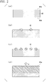
Fig. 2 is a schematic diagram explaining a mechanism of action when the present invention is applied. -
Fig. 3 is a schematic diagram explaining a mechanism of action when the present invention is not applied. - The term "charging" used herein means a reaction in which a metal constituting an anode and lithium is alloyed.
- The term "discharging" used herein means a reaction in which lithium is released from aluminum of the anode.
- In the present specification, a discharge capacity retention rate of a lithium secondary battery is measured by the following method.
- An anode for a current collector-integrated secondary battery of the present embodiment is used as an anode.
- 90 parts by mass of lithium cobalt oxide (product name: CELLSEED, manufactured by Nippon Chemical Industrial CO., LTD., average particle size (D50): 10 µm) as a cathode active material, 5 parts by mass of polyvinylidene fluoride (manufactured by Kureha Corporation) as a binder, and 5 parts by mass of acetylene black (product name: Denka Black, manufactured by Denka Company Limited) as a conductive material are mixed, and 70 parts by mass of N-methyl-2-pyrrolidone is further mixed with the mixture to prepare an electrode mixture for the cathode.
- The obtained electrode mixture is coated onto an aluminum foil having a thickness of 15 µm, which is a current collector, by a doctor blade method. The coated electrode mixture is dried at 60°C for 2 hours and vacuum-dried at 150°C for 10 hours to volatilize N-methyl-2-pyrrolidone. A coating amount of the cathode active material after drying is 21.5 mg/cm2.
- After a laminate of the obtained electrode mixture layer and the current collector is rolled, the laminate is cut into a disk shape of ϕ 14 mm to manufacture a cathode, which is a laminate of a cathode mixture layer as a material for forming lithium cobalt oxide, and the current collector.
- A thickness of the cathode mixture layer after rolling is 60 µm or more and 65 µm or less, and an electrode density is 3.0 g/cm3 or more and 3.5 g/cm3 or less.
- An electrolytic solution obtained by dissolving LiPF6 in a mixed solvent obtained by mixing ethylene carbonate (EC) and diethyl carbonate (DEC) in EC:DEC = 30:70 (volume ratio) in a ratio of 1 mol/L is prepared.
- A polyethylene porous separator is disposed between the anode for a current collector-integrated secondary battery and the cathode described above and stored in a battery case (standard 2032), the electrolytic solution is injected thereinto to seal the battery case, thereby manufacturing a coin-type (full cell) lithium secondary battery having a diameter of 20 mm and a thickness of 3.2 mm.
- The work of using a material that reacts with water, such as an electrolytic solution and an electrode after charging with lithium metal, is performed inside a glove box controlled to have a water value of 1 ppm or less. When the glove box is not used, work is performed in an environment having the same amount of water as the glove box and avoiding contact with water as much as possible.
- The coin-type lithium secondary battery is allowed to stand at room temperature for 10 hours to sufficiently impregnate the separator and the cathode mixture layer with the electrolytic solution.
- Next, initial charging and discharging is performed by charging (absorbing Li to Al) to 4.2 V at a constant current of 1 mA at room temperature, constant-current/constant-voltage charging for charging at a constant voltage of 4.2 V for 5 hours, and then discharging (releasing Li from Al) to 3.4 V at a constant current of 1 mA.
- A value obtained by measuring the discharge capacity is referred to as an "initial discharge capacity" (mAh).
- After the initial charging and discharging, charging at 1 mA and discharging at 1 mA are repeated in the same manner and under the same conditions as the initial charging and discharging.
- The life evaluation in tests at the 20th cycle is measured, and a discharge capacity retention rate is calculated by the following
Expression


- When the discharge capacity retention rate calculated by the above-described (Expression 1) or (Expression 2) is 80% or more, it is evaluated that the discharge capacity of the lithium secondary battery can be maintained even when the cycle is repeated.
- Hereinafter, the "anode for a current collector-integrated secondary battery" may be abbreviated as a "current collector-integrated anode".
- The current collector-integrated anode serves as both the anode and the anode current collector. That is, the current collector-integrated anode does not require a separate current collector member.
- Further, in the manufacturing process of a secondary battery, a process of supporting the anode active material by the current collector is not required.
- Moreover, when the anode active material is supported by a current collector of a separate member, a problem in that an anode active material layer is easily peeled off from the current collector occurs. The current collector-integrated anode is one member with the current collector and the anode. Therefore, there is an advantage in that the problem of peeling-off of the current collector and the anode active material layer does not occur in the first place.
- The current collector-integrated anode is a plate-shaped metal anode. The current collector-integrated anode includes an anode surface and a current collector surface.
- The anode surface of the current collector-integrated anode is involved in charging or discharging and functions as an anode. The current collector surface of the current collector-integrated anode is formed of an excessive metal component that is not involved in charging or discharging, and functions as a current collector.
- In the present embodiment, the term "plate shape (plate-shaped)" means a three-dimensional shape having at least two facing planes.
- In the "plate-shaped" metal anode, a distance between the two facing planes described above corresponds to a thickness of the metal anode. Various values can be adopted for the thickness of the metal anode. The plate-shaped metal anode includes a thin film-shaped electrode having flexibility that is easy to curve or bend, and a thin plate-shaped electrode that is difficult to curve or bend.
- An average crystal grain size when a cross section of the metal anode is observed in a scanning ion microscope (SIM) image is 200 µm or less. Hereinafter, an observation by the scanning ion microscope image may be referred to as "SIM observation", an image observed by the scanning ion microscope image may be referred to as a "SIM image", and a photograph obtained by the scanning ion microscope image observation may be referred to as a "SIM photograph".
- The average crystal grain size of crystal grains is preferably 100 µm or less, more preferably 50 µm or less, still more preferably 10 µm or less, and particularly preferably 5 µm or less.
- The average crystal grain size is preferably 1 µm or more in terms of reducing production costs.
- The above-described upper limit value and lower limit value of the average crystal grain size can be randomly combined together.
- Examples of the combination of the upper limit value and the lower limit value of the average crystal grain size include 1 µm or more and 200 µm or less, 1 µm or more and 100 µm or less, 1 µm or more and 50 µm or less, and 1 µm or more and 5 µm or less.
- SIM observation of a cross section of the metal anode can be performed by the following method.
- First, an uncharged plate-shaped metal foil is processed to form a cross section. The following focused ion beam processing apparatus or composite beam processing observation apparatus is used for processing. Specifically, the metal anode is cut in a direction perpendicular to the surface of the metal anode facing the cathode using the following apparatus to obtain a cross section.
- Next, the obtained cross section is observed using the following focused ion beam processing apparatus or composite beam processing observation apparatus.
-
- Focused ion beam processing observation apparatus: FB-2100 (manufactured by Hitachi High-Technologies Corporation)
- Ion source: gallium liquid metal
- Acceleration voltage: 40 kV
- Magnification: x700 or more and x50,000 or less
-
- Composite beam processing observation apparatus: JIB-4500 (JEOL Ltd.)
- Ion source: gallium liquid metal
- Acceleration voltage: 1 kV or more and 30 kV or less
- Magnification: x100 or more and x300,000 or less (low magnification mode: x30)
- The average crystal grain size of the crystal grains observed when the cross section of the metal anode is observed by SIM is obtained by the following method.
- First, 50 crystal grains are arbitrarily extracted from the SIM photograph obtained by the above method.
- Next, for each of the crystal grains, the distance between parallel lines that are drawn in a predetermined direction to sandwich the projected image of the crystal grains (directed diameter) is measured as the crystal grain size of the crystal grains.
- An arithmetic average value of the obtained crystal grains is set as the average crystal grain size of the crystal grains.
- When a current collector-integrated anode having small metal crystal grains constituting the anode surface is used, the discharge capacity of the lithium secondary battery can be maintained even when the cycle is repeated. This will be described by taking a case where the metal constituting the anode surface is aluminum as an example.
- A current collector-integrated
anode 40 shown inFig. 2(a) includes ananode surface 40a and acurrent collector surface 40b. Theanode surface 40a includes crystal grains having a crystal grain size of 200 µm or less, which is obtained by the SIM observation of the cross section. - When lithium is absorbed in the
anode surface 40a, aluminum-lithium alloy particles 41 are formed. This situation is shown inFig. 2(b) . - As the absorption of lithium proceeds, lithium is selectively absorbed in gaps between the aluminum-
lithium alloy particles 41. This situation is shown inFig. 2(c) . Therefore, the aluminum-lithium alloy particles 41 are uniformly formed on the surface facing the cathode. - When the formation of the aluminum-
lithium alloy particles 41 proceeds uniformly, it is presumed that the aluminum-lithium alloy particles 41 become an aluminum-lithiumalloy particle layer 41a. Therefore, it is presumed that reaction proceeds in a direction represented by a reference sign X inFig. 2(d) and the aluminum-lithiumalloy particle layer 41a expands in the vertical direction. Specifically, the direction represented by the reference sign X is a direction perpendicular to the surface facing the cathode. In this case, it is considered that deformation such as wrinkles and cracks hardly occurs on the electrode. If the deformation hardly occurs, the current collector-integrated anode is unlikely to deteriorate during charge and discharge. Therefore, it is considered that the discharge capacity of the lithium secondary battery can be maintained even when the cycle is repeated. - On the other hand, a case where the crystal grain size is large and the above range is not satisfied will be described with reference to
Fig. 3 . - A current collector-integrated
anode 50 shown inFig. 3(a) includes ananode surface 50a and acurrent collector surface 50b. Theanode surface 50a includes crystal grains having a crystal grain size of 200 µm or less, which is obtained by the SIM observation of the cross section. - When lithium is absorbed in the anode surface, aluminum-
lithium alloy particles 51 are formed. This situation is shown inFig. 3(b) . Astrain 52 shown inFig. 3(b) is generated around the aluminum-lithium alloy particle 51. - Moreover, as the absorption of lithium proceeds, lithium is selectively absorbed in the
strain 52, and the aluminum-lithium alloy particle 51 is locally grown. This situation is shown inFig. 3(c) . Therefore, it is presumed that the aluminum-lithium alloy particle layer 51a expands in directions represented by reference signs Y1 and Y2 inFig. 3(d) . Specifically, the direction represented by the reference sign Y1 is a direction perpendicular to the surface facing the cathode. Specifically, the direction represented by the reference sign Y2 is a direction parallel to the surface facing the cathode. The aluminum-lithium alloy particle layer 51a also expands in a direction represented by the reference sign Y2, in addition to the direction represented by the reference sign Y1. - As a result, wrinkles, cracks, and the like are generated on the electrode, and the electrode is easily deformed. This causes deterioration during charge and discharge.
- An action effect has been described by taking a case where the metal constituting the anode surface is aluminum as an example, but it is considered that the same action is obtained even if silicon, tin, and lead are used.
- The metal constituting the metal anode preferably contains one or more selected from the group consisting of aluminum, silicon, tin, and lead.
- Specifically, as the metal constituting the metal anode, high-purity aluminum, alloys of high-purity aluminum with other metals, high-purity silicon, high-purity tin, and high-purity lead are exemplary examples. The metal constituting the metal anode is preferably aluminum, and more preferably high-purity aluminum or an alloy of high-purity aluminum with another metal.
- The metal anode is preferably high-purity aluminum or a high-purity aluminum alloy.
- The high-purity aluminum is aluminum having a purity of 99% by mass.
- The high-purity aluminum alloy is an alloy of aluminum having a purity of 99% by mass with another metal.
- High-purity aluminum will be described.
- The purity of the high-purity aluminum is preferably 99% by mass or more, more preferably 99.9% by mass or more, still more preferably 99.95% by mass or more, and particularly preferably 99.99% by mass or more. The purity of high-purity aluminum can be confirmed by a solid emission spectrochemical analysis method.
- An example of the purification method for purifying aluminum to the above-described purity can include a segregation method and a three-layer electrolysis method.
- The segregation method is a purification process that utilizes a segregation phenomenon when molten aluminum is easily solidified. As for the segregation method, a plurality of methods have been put into practical use. As for one form of the segregation method, there is a method of pouring molten aluminum into a container, and solidifying the purified aluminum from the bottom while heating and stirring the molten aluminum at the top while rotating the container. Aluminum having a purity of 99% by mass or more can be obtained by the segregation method.
- As one form of the three-layer electrolysis method, first, an aluminum (for example, about one grade having a purity of 99% by mass in JIS-H2102) is charged into an Al-Cu alloy layer. The aluminum metal is then used as an anode in a molten state, and an electrolytic bath containing, for example, aluminum fluoride and barium fluoride is disposed thereon to precipitate high-purity aluminum on a cathode.
- The high-purity aluminum having a purity of 99.999% by mass or more can be obtained by the three-layer electrolysis method.
- The refining method for highly purifying aluminum is not limited to the segregation method and the three-layer electrolysis method, and other known methods such as a zone melting refining method and an ultra-high vacuum melting refining method may be used.
- As an element added to the high-purity aluminum to form a high-purity aluminum alloy, one or more elements selected from the group consisting of Si, Ge, Mg, Ni, Mn, Zn, and Cd are exemplary examples. These elements may be referred to as intentionally added elements.
- When an alloy of high-purity aluminum and another metal is used, a content of another metal contained in the total amount of the high-purity aluminum alloy is preferably 0.1% by mass or more, more preferably 0.5% by mass or more, and still more preferably 0.7% by mass or more.
- In addition, the content of another metal contained in the total amount of the high-purity aluminum alloy is 1.0% by mass or less, more preferably 0.9% by mass or less, and still more preferably 0.8% by mass or less.
- The above-described upper limit value and lower limit value can be randomly combined together. The content of another metal contained in the total amount of the high-purity aluminum alloy is preferably 0.1% by mass or more and 1.0% by mass or less, more preferably 0.5% by mass or more and 0.9% by mass or less, and particularly preferably 0.7% by mass or more and 0.8% by mass or less.
- In the high-purity aluminum alloy, a total content of the metal components excluding the intentionally added elements is preferably 0.1% by mass or less, more preferably 0.05% by mass or less, and still more preferably 0.01% by mass, with respect to the total amount of the aluminum alloy.
- The lower limit value of the total content of the metal components excluding the intentionally added element is not particularly limited, and examples thereof include 0% by mass or more, 0.0001% by mass or more, and 0.0002% by mass or more.
- When the metal constituting the metal anode is aluminum, a Vickers hardness of the anode surface is at least preferably 10 HV or more and 70 HV or less, more preferably 20 HV or more and 70 HV or less, and still more preferably 30 HV or more and 70 HV or less.
- If the Vickers hardness is the upper limit value or less, it is presumed that a strain of a crystal structure when lithium is absorbed can be relaxed, and the crystal structure can be thus maintained. Therefore, the discharge capacity of the lithium secondary battery can be maintained even when the cycle of the lithium secondary battery using the current collector-integrated anode is repeated.
- If the Vickers hardness is equal to or more than the above lower limit value, the current collector-integrated anode hardly deteriorates during charge and discharge. Therefore, the discharge capacity of the lithium secondary battery can be maintained even when the cycle is repeated.
- For the Vickers hardness, a value measured by the following method is used.
- As the metal anode, the Vickers hardness (HV 0.05) is measured using a micro-Vickers hardness tester. A micro-Vickers hardness is an index of hardness.
- The Vickers hardness is a value measured according to JIS Z2244: 2009 "Vickers hardness test-test method".
- The method for measuring Vickers hardness is as follows.
- First, a diamond indenter having a regular quadrangular pyramid shape is pushed into a surface of the metal anode as a test piece with a predetermined test force.
- Next, after the test force is released, a surface area of a dent is calculated from a diagonal length of the dent remaining on the surface of the metal anode as the test piece. A value obtained by dividing the test force by the surface area is the Vickers hardness.
- It stipulates in JIS Z2244:2009 that a hardness symbol is changed according to the test force. In the present embodiment, the micro-Vickers hardness of HV 0.05 is used when the test force is 0.05 kgf (= 0.4903 N).
- The thickness of the current collector-integrated anode is preferably 5 µm or more, more preferably 6 µm or more, and still more preferably 7 µm or more. In addition, the thickness of the
metal anode 3 is preferably 200 µm or less, more preferably 190 µm or less, and particularly preferably 180 µm or less. - The above-described upper limit value and lower limit value can be randomly combined together.
- As an example of the combination, the thickness of the current collector-integrated anode is preferably 5 µm or more and 200 µm or less, more preferably 6 µm or more and 190 µm or less, and particularly preferably 7 µm or more and 180 µm or less.
- Moreover, the thickness of the current collector-integrated anode is preferably 5 µm or more, more preferably 10 µm or more, and still more preferably 20 µm or more. In addition, the thickness of the current collector-integrated anode is preferably 200 µm or less, more preferably 100 µm or less, and particularly preferably 50 µm or less.
- The above-described upper limit value and lower limit value can be randomly combined together.
- As an example of the combination, the thickness of the current collector-integrated anode is preferably 5 µm or more and 200 µm or less, more preferably 10 µm or more and 100 µm or less, and particularly preferably 20 µm or more and 50 µm or less.
- The thickness of the current collector-integrated anode may be measured using a thickness gauge or a caliper.
- The thickness of the current collector-integrated anode means an average value when the thickness of the current collector-integrated anode is measured at five points.
- The current collector-integrated anode can be manufactured by a manufacturing method including a casting step and a foil shape processing step in order.
- In the casting step, a treatment for melting aluminum at about 680°C or higher and 800°C or lower and removing and purifying known gas or non-metal inclusions (for example, vacuum treatment of molten alloy) is performed.
- The vacuum treatment is performed under conditions of, for example, 700°C or higher and 800°C or lower, 1 hour or longer and 10 hours or shorter, and a vacuum degree of 0.1 Pa or higher and 100 Pa or lower.
- As a treatment for purifying the high-purity aluminum or high-purity aluminum alloy, a treatment for blowing flux, inert gas, or chlorine gas into the molten aluminum can be also used.
- The molten metal purified by the vacuum treatment or the like is usually cast in a casting mold to obtain an aluminum ingot. The casting mold is obtained by using iron or graphite heated to 50°C or higher and 200°C or lower. Aluminum is cast by a method of pouring a molten alloy at 680°C or higher and 800°C or lower into the casting mold. In addition, ingots can also be obtained by continuous casting, which is generally used.
- An aluminum alloy ingot can be obtained by adding a predetermined amount of other metal elements to be alloyed during melting in the above-described casting step.
- The obtained aluminum ingot or aluminum alloy ingot is processed into a foil shape by subjecting to a rolling process, an extruding process, a casting process, and the like to prepare a raw material of the metal foil.
- When a plate-shaped metal anode is used, the aluminum ingot or aluminum alloy ingot may be processed into a plate shape in a foil shape processing step.
- In the rolling process of the ingot, for example, hot rolling and cold rolling are performed to process the aluminum ingot or the aluminum alloy ingot into a foil shape.
- Examples of a temperature condition for performing hot rolling include a temperature of the aluminum ingot or the aluminum alloy ingot of 350°C or higher and 450°C or lower.
- In the rolling process, the material repeatedly passes between a pair of rolling rolls to achieve a target thickness. Passing between the pair of rolling rolls is referred to as "pass".
- A working ratio r (%) per pass is a thickness reduction ratio when passing through the rolling roll once, and calculated by the following expression.

- In the foil shape processing step, it is preferable that the aluminum ingot or the aluminum alloy ingot be repeatedly rolled so as to have the target thickness under a condition of the working ratio r per pass of 2% or more and 20% or less.
- After hot rolling and before cold rolling, a process annealing treatment may be performed.
- In the process annealing treatment, for example, the hot-rolled aluminum ingot or aluminum alloy ingot may be heated to 350°C or higher and 450°C or lower, and may be allowed to cool immediately after raising the temperature.
- In addition, the aluminum ingot or the aluminum alloy ingot may be allowed to cool for about 1 hour or longer to 5 hours or shorter.
- By the process annealing treatment, the material of the aluminum ingot or the aluminum alloy ingot is softened to be in a state in which it is easily cold-rolled.
- Cold rolling is performed, for example, at a temperature lower than a recrystallization temperature of the aluminum ingot or the aluminum alloy ingot. For example, the cold rolling may be usually performed at a temperature from room temperature to 80°C or lower. In this case, the aluminum ingot is repeatedly cold-rolled so as to have the target thickness in the die per pass under a condition of the working ratio r of 1% or more and 10% or less.
- A rolled material obtained by the rolling process is subjected to a heat treatment for adjusting physical properties in general. The heat treatment after rolling is referred to as a rolled material heat treatment step.
- An average crystal grain size of the rolled material can be adjusted depending on alloy compositions, rolling conditions, conditions for the rolled material heat treatment step, and the like. Among them, the average crystal grain size of the rolled material is easily affected by the conditions of the rolled material heat treatment step. For example, the higher the heat treatment temperature in the rolled material heat treatment step and the longer the heat treatment time, the larger the average crystal grain size.
- In order to set the average crystal grain size to 200 µm or less, it is preferable not to perform the rolled material heat treatment step. More specifically, in order to set the average crystal grain size to 200 µm or less, it is preferable not to perform the rolled material heat treatment step at a high temperature of 450°C or higher, for example.
- Moreover, in a case of performing the rolled material heat treatment step, it is preferable to perform the rolled material heat treatment step under the heat treatment condition capable of maintaining a range of the Vickers hardness exceeding 50% as compared with that before the heat treatment. Specifically, for example, conditions at a temperature range of 50°C or higher and 300°C or lower for 1 hour or longer and 15 hours or shorter in the atmosphere are exemplary examples. In addition, for example, conditions at a temperature range of 50°C or higher and 400°C or lower for 1 hour or longer and 15 hours or shorter in the atmosphere are exemplary examples.
- A lithium secondary battery will be described. The work of using a material that reacts with water, such as an electrolytic solution and an electrode after charging with lithium metal, is performed inside a glove box controlled to have a water value of 1 ppm or less. When the glove box is not used, work is performed in an environment having the same amount of water as the glove box and avoiding contact with water as much as possible.
- The lithium secondary battery includes an electrode group including an anode for a current collector-integrated secondary battery, an electrolyte, and a cathode. The anode for a current collector-integrated secondary battery includes an anode surface and a current collector surface.
- Hereinafter, a lithium secondary battery using a lithium cathode active material will be described as an example.
- The anode for a current collector-integrated secondary battery is a plate-shaped metal anode. An average crystal grain size of the observed crystal grains when a cross section of the metal anode is observed in a scanning ion microscope (SIM) image is 200 µm or less.
- Further, the anode for a current collector-integrated secondary battery satisfies one or both of the following
Requirement - When the anode for a current collector-integrated secondary battery absorbs and expands lithium ions, a ratio of a linear expansion coefficient β1 in a direction perpendicular to the surface facing the cathode to a linear expansion coefficient β2 in a direction parallel to the surface facing the cathode (β1/β2) exceeds 1.3.
- The ratio of the linear expansion coefficient (β1/β2) specified in
Requirement 1 can be measured by the following method. - First, lithium ions of 5 mAh/cm2 are absorbed in the anode for a current collector-integrated secondary battery at a current density of 0.5 mA/cm2.
- Next, each of the linear expansion coefficient β1 in the direction perpendicular to the surface facing the cathode and the linear expansion coefficient β2 in the direction parallel to the surface facing the cathode is calculated by the following methods.
- Perpendicular direction expansion coefficient β1: First, thicknesses of the current collector-integrated anode are measured at 10 points before and after charging with a micrometer. Next, an average value of each of the thicknesses before and after charging is obtained. The perpendicular direction expansion coefficient β1 is the average value of the thickness after charging/the average value of the thickness before charging.
- Parallel direction expansion coefficient β2: Widths of the current collector-integrated anode are measured at 10 points before and after charging with an optical microscope. The width of the current collector-integrated anode is a width of the current collector-integrated anode in a longitudinal direction. Next, an average value of each of the widths before and after charging is obtained. The parallel direction expansion coefficient β2 is the average value of the width after charging/the average value of the width before charging.
- Next, the ratio of the linear expansion coefficient (β1/β2) is obtained.
- The ratio of the linear expansion coefficient (β1/β2) is preferably 1.4 or more, more preferably 1.5 or more, and particularly preferably 1.7 or more.
- When the ratio of the linear expansion coefficient (β1/β2) is equal to or more than the above lower limit value, it means that an aluminum-lithium alloy uniformly expands in the direction perpendicular to the surface facing the cathode.
- In this case, crystal defects are less likely to occur, and the anode current collector is less likely to deteriorate during charge and discharge. Therefore, it is considered that the discharge capacity of the lithium secondary battery can be maintained even when the cycle is repeated.
- Further, it is considered that if unevenness, cracks, and the like occur on the surface of the anode facing the cathode after expansion or contraction and a specific area increases, a reaction specific surface area of the surface in the following absorbing and releasing of lithium increases, and a reaction speed increases.
- The upper limit value of the ratio of linear expansion coefficient (β1/β2) is not particularly limited, and examples thereof include 5 or less, 4 or less, and 3 or less.
- The above-described upper limit value and lower limit value of the ratio of linear expansion coefficient (β1/β2) can be randomly combined together.
- As an example of the combination, the ratios (β1/β2) of 1.4 or more and 5 or less, 1.5 or more and 4 or less, and 1.7 or more and 3 or less are exemplary examples.
- The anode for a current collector-integrated secondary battery has an average particle size of lithium alloy particles observed under the following conditions of less than 100 µm.
- First, lithium ions of 2 mAh/cm2 are absorbed in the anode for a current collector-integrated secondary battery at a current density of 0.5 mA/cm2.
- Next, the average particle size of the lithium alloy particles present in the anode surface is calculated from an image obtained by SEM observation.
- When lithium ions are absorbed in the current collector-integrated anode, lithium alloy particles are formed on the anode surface. The lithium alloy particles are, for example, lithium-aluminum alloys. When the anode surface is observed by the SEM after lithium ions are absorbed, the particles are observed on the anode surface.
- When lithium ions are generated according to the above [Conditions], all the observed particles are determined as lithium alloy particles, and the average particle size thereof is measured.
- The average particle size of lithium alloy particles is obtained by the following method.
- First, the anode for a current collector-integrated secondary battery after lithium absorption is placed on a sample stage.
- Next, an electron beam having an acceleration voltage of 20 kV is irradiated to perform the SEM observation on the anode for a current collector-integrated secondary battery with JSM-5510 manufactured by JEOL Ltd. Here, the magnification is x100 or more and x2000 or less.
- Next, 50 lithium alloy particles are randomly extracted from an image obtained by the SEM observation (SEM photograph). For each of the extracted lithium alloy particles, the distance between parallel lines that are drawn in a predetermined direction to sandwich the projected image of the lithium alloy particle (directed diameter) is measured as the particle size of the lithium alloy particle. The arithmetic average value of the obtained particle size of the lithium alloy particles is regarded as the average particle size of the lithium alloy particles.
- The average particle size of the lithium alloy particles specified in
Requirement 2 is preferably 100 µm or less, more preferably 50 µm or less, and particularly preferably 20 µm or less. - When the average particle size of the lithium alloy particles is equal to or less than the above upper limit value, it means that, for example, the aluminum-lithium alloy is not locally grown, and the aluminum-lithium alloy uniformly expands in a direction perpendicular to the surface facing the cathode.
- In this case, crystal defects are less likely to occur, and the current collector-integrated anode is less likely to deteriorate during charge and discharge. Therefore, it is considered that the discharge capacity of the lithium secondary battery can be maintained even when the cycle is repeated.
- The lower limit value of the average particle size of lithium alloy particles specified in
Requirement 2 is not particularly limited, and examples thereof include 1 µm or more, 2 µm or more, and 3 µm or more. - The above-described upper limit value and lower limit value of the average particle size of the lithium alloy particles specified in
Requirement 2 can be randomly combined together. - As an example of the combination, the average particle sizes of the lithium alloy particles specified in
Requirement 2 of 1 µm or more and 100 µm or less, 2 µm or more and 50 µm or less, and 3 µm or more and 20 µm or less are exemplary examples. - The current collector-integrated anode may satisfy either
Requirement 1 orRequirement 2 or preferably satisfies bothRequirement 1 andRequirement 2. - The current collector-integrated anode preferably contains one or more selected from the group consisting of aluminum, silicon, tin, and lead.
- The current collector-integrated anode preferably has the Vickers hardness of the anode surface of at least 10 HV or more and 70 HV or less.
- It is preferable that there be no change in a profile obtained when the anode surface of the current collector-integrated anode is subjected to X-ray diffraction measurement using CuKα as a radiation source, in a case where a measurement position is changed on the surface of the metal anode.
- The X-ray diffraction measurement using CuKα as a radiation source is specifically, for example, a measurement in which a range of 2θ is set to 10° to 90° by the following apparatus and measurement conditions.
-
- Apparatus: X-ray diffractometer X'Pert PRO MPD (Spectris), slit width: 2 mm
- Voltage: 45 KV
- Current: 40 mA
- Scan speed: 4 °/min
- Step: 0.016°
- If there is no change in the profile obtained by the above X-ray diffraction measurement even if the measurement position on the surface of the metal anode is changed, it is considered that an average profile having little unevenness in the crystal orientation and many crystal grains is obtained. Therefore, it is presumed that the size of crystal grains of the metal anode is small, and as a result,
Requirement 2 is as small as less than 100 µm. - Here, the expression "there is no change in the profile" means that a peak position of the maximum intensity of an XRD profile and a peak position of the second highest intensity match even if the measurement position is changed. In addition, the change in the peak position includes a shift due to a slight structural change. Thus, if the change is within ±2° based on a peak top, it is determined that the peak position of the maximum intensity and the peak position of the second highest intensity are at the same peak and match, which is referred to as "there is no change in the profile".
- On the other hand, when the measurement position is changed, it is determined that "there is a change in the profile" in a case where the peak position of the maximum intensity of the XRD profile or the peak position of the second highest intensity is different. In this case, it is considered that the size of crystal grains of the metal anode is large with respect to an irradiation diameter of the XRD, and the profile of specific crystal grains is obtained. Therefore, as a result,
Requirement 2 exceeds 100 µm and the size of crystal grains of the metal anode is large. - The cathode can be manufactured by, first, adjusting a cathode mixture containing a cathode active material, a conductive material, and a binder and supporting the cathode mixture by a cathode current collector.
- As the cathode active material, a material formed of a lithium-containing compound or another metal compound can be used. Examples of the lithium-containing compound include a lithium cobalt composite oxide having a layered structure, a lithium nickel composite oxide having a layered structure, and a lithium manganese composite oxide having a spinel structure.
- Further, examples of another metal compound include oxides such as titanium oxide, vanadium oxide, or manganese dioxide, and sulfides such as titanium sulfide or molybdenum sulfide.
- As the conductive material in the cathode, a carbon material can be used. As the carbon material, graphite powder, carbon black (for example, acetylene black), a fibrous carbon material, and the like can be exemplary examples.
- Carbon black is fine and has a large surface area. Therefore, conductivity inside the cathode can be enhanced by adding a small amount of the conductive material to the cathode mixture, and a charge/discharge efficiency and output characteristics can be improved.
- On the other hand, when an excess of carbon black is added, both the binding force between the cathode mixture and the cathode current collector attributed to the binder and the binding force inside the cathode mixture deteriorate, which, conversely, acts as a cause for an increase in the internal resistance.
- The fraction of the conductive material in the cathode mixture is preferably 5 parts by mass or more and 20 parts by mass or less with respect to 100 parts by mass of the cathode active material. In the case of using a fibrous carbon material such as a graphitized carbon fiber or a carbon nanotube as the conductive material, it is also possible to decrease the fraction of the conductive material in the cathode mixture.
- A thermoplastic resin can be used as a binder in the cathode. As the thermoplastic resin, fluororesins and polyolefin resins can be exemplary examples.
- As the fluororesin, polyvinylidene fluoride (hereinafter, referred to as PVdF in some cases), polytetrafluoroethylene (hereinafter, referred to as PTFE in some cases), tetrafluoroethylene-hexafluoropropylene-vinylidene fluoride-based copolymers, hexafluoropropylene-vinylidene fluoride-based copolymers, and tetrafluoroethylene-perfluorovinyl ether-based copolymer can be exemplary examples.
- As the polyolefin resin, polyethylene and polypropylene are exemplary examples.
- Two or more of these thermoplastic resins may be used in a mixture form. For example, a binder using a fluororesin and a polyolefin resin can be used.
- In this case, it is preferable that a ratio of the fluororesin to the entire cathode mixture be 1% by mass or more and 10% by mass or less, and a ratio of the polyolefin resin to the entire cathode mixture be 0.1% by mass or more and 2% by mass or less. As a result, it is possible to obtain a cathode mixture having a high adhesive force to the cathode current collector and a high bonding force inside the cathode mixture.
- As the cathode current collector in the cathode, a strip-shaped member formed of a metallic material such as Al, Ni, or stainless steel as a forming material can be used. Particularly, as the current collector, a current collector that is formed of Al and has a thin film shape is preferable in terms of easy processing and low price.
- As the method for supporting the cathode mixture by the cathode current collector, a method in which the cathode mixture is formed by pressurization on the cathode current collector is an exemplary example. In addition, the cathode mixture may be supported by the cathode current collector by preparing a paste of the cathode mixture using an organic solvent, applying and drying the paste of the cathode mixture to be obtained on at least one surface side of the cathode current collector, and fixing the cathode mixture by pressing.
- As the organic solvent that can be used when the cathode mixture is pasted, an amine-based solvent, an ether-based solvent, a ketone-based solvent, an ester-based solvent, and an amide-based solvent are exemplary examples.
- As the amine-based solvent, N,N-dimethylaminopropylamine, diethylenetriamine and the like are exemplary examples.
- As the ether solvent, tetrahydrofuran is an exemplary example.
- As the ketone solvent, methyl ethyl ketone is an exemplary example.
- As the amide-based solvent, dimethylacetamide and N-methyl-2-pyrrolidone are exemplary examples.
- As the method for applying the paste of the cathode mixture to the cathode current collector, a slit die coating method, a screen coating method, a curtain coating method, a knife coating method, a gravure coating method, and an electrostatic spraying method are exemplary examples.
- The cathode can be manufactured by the method described above.
- Examples of the separator can include materials having a form such as a porous film, a non-woven fabric, or a woven fabric. These materials are formed of, for example, polyolefin resins such as polyethylene and polypropylene, fluororesins, nitrogen-containing aromatic polymers, and the like. In addition, the separator may be formed using two or more of these materials or the separator may be formed by laminating these materials.
- An air resistance of the separator by the Gurley method specified by JIS P 8117 is preferably 50 sec/100 cc or more and 300 sec/100 cc or less, more preferably 50 sec/100 cc or more, and still more preferably 200 sec/100 cc or less, in order to favorably permeate the electrolyte while the battery is in use (while the battery is being charged and discharged).
- Further, a porosity of the separator is preferably 30 vol% or more and 80 vol% or less and more preferably 40 vol% or more and 70 vol% or less. The separator may be a laminate in which separators having different porosities are laminated.
- The electrolytic solution contains an electrolyte and an organic solvent.
- As the electrolyte that is contained in the electrolytic solution, lithium salts such as LiClO4, LiPF6, LiAsF6, LiSbF6, LiBF4, LiCF3SO3, LiN(SO2CF3)2, LiN(SO2C2F5)2, LiN(SO2CF3)(COCF3), Li(C4F9SO3), LiC(SO2CF3)3, Li2B10Cl10, LiBOB (here, BOB represents bis(oxalato)borate), LiFSI (here, FSI represents bis(fluorosulfonyl)imide), lower aliphatic carboxylic acid lithium salts, and LiAlCl4 are exemplary examples. As the electrolyte, a mixture of two or more of these may be used.
- Among these, an electrolyte containing at least one selected from the group consisting of LiPF6, LiAsF6, LiSbF6, LiBF4, LiCF3SO3, LiN(SO2CF3)2, and LiC(SO2CF3)3 that contain fluorine is preferably used as the electrolyte.
- Moreover, as the organic solvent contained in the electrolytic solution, carbonates, ethers, esters, nitriles, amides, carbamates, sulfur-containing compounds, or solvents obtained by further introducing a fluoro group into the above-described organic solvent (solvents in which one or more hydrogen atoms contained in the organic solvent is substituted by a fluorine atom) can be used.
- Examples of the carbonates include propylene carbonate, ethylene carbonate, dimethyl carbonate, diethyl carbonate, ethylmethyl carbonate, 4-trifluoromethyl-1,3-dioxolan-2-one, and 1,2-di (methoxycarbonyloxy)ethane.
- Examples of the ethers include 1,2-dimethoxyethane, 1,3-dimethoxypropane, pentafluoropropylmethyl ether, 2,2,3,3-tetrafluoropropyldifluoromethyl ether, tetrahydrofuran, and 2-methyltetrahydrofuran.
- As the esters, methyl formate, methyl acetate, and γ-butyrolactone are exemplary examples.
- As the nitriles, acetonitrile and butyronitrile are exemplary examples.
- As the amides, N,N-dimethylformamide and N,N-dimethylacetamide are exemplary examples.
- As the carbamates, 3-methyl-2-oxazolidone is an exemplary example.
- As the sulfur-containing compound, sulfolane, dimethyl sulfoxide, and 1,3-propanesarton are exemplary examples.
- As the organic solvent, two or more of the above-described organic solvents are preferably used in a mixture form. Among these, a mixed solvent containing a carbonate is preferable, and a mixed solvent of a cyclic carbonate and a non-cyclic carbonate and a mixed solvent of a cyclic carbonate and an ether are still more preferable.
- As the mixed solvent of a cyclic carbonate and a non-cyclic carbonate, a mixed solvent containing ethylene carbonate, dimethyl carbonate, and ethyl methyl carbonate is preferable.
- The electrolytic solution for which such a mixed solvent is used has a number of features as follows: the electrolytic solution has a broad operating temperature range, does not easily deteriorate even when the lithium secondary battery is charged and discharged at a high current rate, and does not easily deteriorate even after being used for a long period of time.
- Moreover, as the electrolytic solution, it is preferable to use an electrolytic solution containing a lithium salt containing fluorine such as LiPF6 and an organic solvent having a fluorine substituent in terms of enhanced safety of lithium secondary batteries to be obtained.
- A mixed solvent containing an ether having a fluorine substituent such as pentafluoropropyl methyl ether or 2,2,3,3-tetrafluoropropyl difluoromethyl ether and dimethyl carbonate is still more preferable since the discharge capacity retention rate is high even when the lithium secondary battery is charged and discharged at a high current rate.
-
Figs. 1A and 1B are schematic views showing an example of the lithium secondary battery. For example, a cylindrical lithiumsecondary battery 10 is manufactured as described below. - First, as shown in
Fig. 1A , a pair ofseparators 1 having a band shape, a strip-shapedcathode 2 having acathode lead 21 at one end, and a band-shaped current collector-integratedanode 3 having ananode lead 31 at one end are laminated in the order of theseparator 1, thecathode 2, theseparator 1, and the current collector-integratedanode 3 and are wound to form anelectrode group 4. - Next, as shown in
Fig. 1B , theelectrode group 4 and an insulator (not shown) are accommodated in abattery exterior 5, then, a can bottom thereof is sealed, theelectrode group 4 is impregnated with anelectrolytic solution 6, and an electrolyte is disposed between thecathode 2 and theanode 3. Furthermore, the upper portion of thebattery exterior 5 is sealed with atop insulator 7 and a sealingbody 8, which makes it possible to manufacture a lithiumsecondary battery 10. - As the shape of the
electrode group 4, a columnar shape in which the cross-sectional shape becomes a circle, an ellipse, a rectangle, or a rectangle with rounded corners when theelectrode group 4 is cut in a direction perpendicular to the winding axis can be an exemplary example. - Moreover, as the shape of a lithium secondary battery having such an
electrode group 4, a shape that is specified by IEC60086, which is a standard for batteries specified by the International Electrotechnical Commission (IEC), or by JIS C 8500 can be adopted. Shapes such as a cylindrical shape and a square shape can be exemplary examples. - Furthermore, the lithium secondary battery is not limited to the winding-type configuration and may have a lamination-type configuration in which the laminated structure of the cathode, the separator, the anode, and the separator is repeatedly overlaid. As the lamination-type lithium secondary battery, it is possible to exemplify a so-called coin-type battery, a button-type battery, and a paper-type (or sheet-type) battery.
- Next, the present invention will be described in more detail using Examples.
- The SIM observation of the cross section of the metal anode, which is the method described in <SIM Observation of Cross Section of Metal Anode> described above, was performed by [Measurement Method 2].
- The average crystal grain size of the crystal grains was obtained by the method described in <Measurement of Average Crystal Grain Size of Crystal Grains> described above.
- The ratio of the linear expansion coefficient (β1/β2) was obtained by the method described in <Measurement of
Requirement 1>described above. - The average particle size of lithium alloy particles was obtained by the method described in <Measurement of
Requirement 2> described above. - The Vickers hardness was measured by the method described in the above
- 4,600 g of aluminum (purity: 99.99% by mass or more) was weighed.
- Next, a molten aluminum was obtained by melting aluminum.
- Next, the molten aluminum was kept and purified under conditions of a temperature of 740°C for 2 hours and a vacuum degree of 50 Pa.
- The molten aluminum was cast using a casting mold of cast iron (22 mm × 150 mm × 200 mm) and dried at 150°C to obtain an ingot.
- In order to homogenize a crystal structure of the obtained ingot, heat treatment was performed in the air at 580°C for 9 hours.
- Rolling was performed under the following conditions. After both sides of the ingot were chamfered by 2 mm, cold rolling was performed from a thickness of 18 mm at a working ratio r of 99.6%. A thickness of the obtained raw material of the metal foil was 50 µm.
- The cross section of the raw material of the metal foil was subjected to the SIM observation (magnification: x2000) under the above conditions, and crystal grains were thus observed in the raw material of the metal foil used in Example 1. When a size of the crystal grains was observed for 50 crystal grains, the crystal grain size was within a range of 1 µm or more and 20 µm or less.
- Moreover, the Vickers hardness of the raw material of the metal foil was 35 HV.
- The obtained aluminum metal foil (thickness: 50 µm) was cut into a disk shape of ϕ 16 mm to manufacture an anode.
- The discharge capacity retention rate of the lithium secondary battery was measured by the method described in <Measurement of Discharge Capacity Retention Rate> described above.
- In Example 1, the discharge capacity retention rate calculated by (Expression 1) was 82%.
- After the foil shape processing step, a current collector-integrated anode was manufactured and a lithium secondary battery was manufactured in the same manner as in Example 1, except that the heat treatment step was performed at 350°C for 3 hours in an atmosphere.
- In Comparative Example 1, the SIM observation was performed at a magnification of x30 to obtain an average crystal grain size of crystal grains.
- In Comparative Example 1, the discharge capacity retention rate calculated by (Expression 1) was 47%.
[Table 1] Current collector-integrated anode Battery characteristic Average crystal grain size of crystal grains Vickers hardness Requirement 1 Requirement 2Discharge capacity retention rate Example 1 5 µm 35 HV 2 10 µm 82% Comparative Example 1 3000 µm 15 HV 1.1 100 µm 47% - 4,500 g of high-purity aluminum (purity: 99.99% by mass or more) and 45 g of high-purity chemical silicon (purity: 99.999% by mass or more) were mixed, and the mixture was heated to 760°C and held at 760°C to obtain a molten Al-Si alloy having silicon contained in an amount of 1.0% by mass.
- The metal foil of Example 2 was obtained in the same manner as in Example 1, except that the obtained molten Al-Si alloy was used.
- As for the metal foil of Example 2, the SIM observation was performed at a magnification of x2000 to obtain an average crystal grain size of crystal grains.
- In Example 2, the discharge capacity retention rate calculated by (Expression 2) was 96%.
- After the foil shape processing step, a current collector-integrated anode was manufactured and a lithium secondary battery was manufactured in the same manner as in Example 2, except that the heat treatment step was performed at 350°C for 3 hours in an atmosphere.
- In Example 3, the SIM observation was performed at a magnification of x100 to obtain an average crystal grain size of crystal grains.
- In Example 3, the discharge capacity retention rate calculated by (Expression 2) was 88%.
[Table 2] Current collector-integrated anode Battery characteristic Average crystal grain size of crystal grains Vickers hardness Requirement 1 Requirement 2Discharge capacity retention rate Example 2 5 µm 65 HV 1.7 10 µm 96% Example 3 45 µm 20 HV 2.4 50 µm 88% -
- 1: Separator
- 2: Cathode
- 3: Current collector-integrated anode
- 4: Electrode group
- 5: Battery exterior
- 6: Electrolytic solution
- 7: Top insulator
- 8: Sealing body
- 10: Battery
- 21: Cathode lead
- 31: Anode lead
Claims (8)
- An anode for a current collector-integrated secondary battery, comprising:an anode surface; anda current collector surface,wherein the anode for a current collector-integrated secondary battery is a plate-shaped metal anode, andan average crystal grain size of crystal grains observed when a cross section of the metal anode is observed in a scanning ion microscope (SIM) image is 200 µm or less.
- The anode for a current collector-integrated secondary battery according to Claim 1,
wherein a metal constituting the metal anode contains one or more selected from the group consisting of aluminum, silicon, tin, and lead. - The anode for a current collector-integrated secondary battery according to Claim 1 or 2,
wherein the metal constituting the metal anode is aluminum. - The anode for a current collector-integrated secondary battery according to Claim 3,
wherein a Vickers hardness of the anode surface is at least 10 HV or more and 70 HV or less. - A lithium secondary battery, comprising:an electrode group that includes an anode for a current collector-integrated secondary battery including an anode surface and a current collector surface, an electrolyte, and a cathode,wherein the anode for a current collector-integrated secondary battery is a plate-shaped metal anode,an average crystal grain size of crystal grains observed when a cross section of the metal anode is observed in a scanning ion microscope (SIM) image is 200 µm or less, andthe anode for a current collector-integrated secondary battery satisfies one or both of the following Requirements 1 and 2,(Requirement 1)
when the lithium secondary battery is charged, a ratio of a linear expansion coefficient β1 in a direction perpendicular to a surface facing the cathode to a linear expansion coefficient β2 in a direction parallel to the surface facing the cathode (β1/β2) exceeds 1.3,(Requirement 2)
an average particle size of lithium alloy particles observed under the following conditions is less than 100 µm,[Conditions]first, lithium ions of 2 mAh/cm2 are charged to the anode for a current collector-integrated secondary battery at a current density of 0.5 mA/cm2,next, the average particle size of the lithium alloy particles present in the anode surface is calculated from an image obtained by SEM observation. - The lithium secondary battery according to Claim 5,
wherein the anode for a current collector-integrated secondary battery contains one or more selected from the group consisting of aluminum, silicon, tin, and lead. - The lithium secondary battery according to Claim 5 or 6,
wherein the anode for a current collector-integrated secondary battery is aluminum. - The lithium secondary battery according to Claim 7,
wherein a Vickers hardness of the anode surface is at least 10 HV or more and 70 HV or less.
Applications Claiming Priority (2)
| Application Number | Priority Date | Filing Date | Title |
|---|---|---|---|
| JP2019229603 | 2019-12-19 | ||
| PCT/JP2020/046955 WO2021125225A1 (en) | 2019-12-19 | 2020-12-16 | Negative electrode for collector-integrated secondary cell, and lithium secondary cell |
Publications (2)
| Publication Number | Publication Date |
|---|---|
| EP4080605A1 true EP4080605A1 (en) | 2022-10-26 |
| EP4080605A4 EP4080605A4 (en) | 2024-06-05 |
Family
ID=76477536
Family Applications (1)
| Application Number | Title | Priority Date | Filing Date |
|---|---|---|---|
| EP20903484.2A Withdrawn EP4080605A4 (en) | 2019-12-19 | 2020-12-16 | Negative electrode for collector-integrated secondary cell, and lithium secondary cell |
Country Status (6)
| Country | Link |
|---|---|
| US (1) | US20230024005A1 (en) |
| EP (1) | EP4080605A4 (en) |
| JP (1) | JPWO2021125225A1 (en) |
| KR (1) | KR20220116167A (en) |
| CN (1) | CN114868280A (en) |
| WO (1) | WO2021125225A1 (en) |
Families Citing this family (3)
| Publication number | Priority date | Publication date | Assignee | Title |
|---|---|---|---|---|
| CN117501467A (en) * | 2021-06-22 | 2024-02-02 | 松下知识产权经营株式会社 | Wound type non-aqueous electrolyte battery |
| JP2024060936A (en) * | 2022-10-20 | 2024-05-07 | 住友化学株式会社 | Anode for lithium secondary battery, precursor for anode for lithium secondary battery, lithium secondary battery, and method for producing anode for lithium secondary battery |
| CN121123355A (en) * | 2024-06-11 | 2025-12-12 | 通用汽车环球科技运作有限责任公司 | Battery pack with large grain boundaries and pre-lithiated aluminum anode electrode |
Family Cites Families (10)
| Publication number | Priority date | Publication date | Assignee | Title |
|---|---|---|---|---|
| GB8915252D0 (en) * | 1989-07-03 | 1989-08-23 | Alcan Int Ltd | Battery autofocus camera |
| JPH04206263A (en) * | 1990-11-29 | 1992-07-28 | Seiko Instr Inc | Nonaqueous electrolyte secondary battery |
| JPH07320723A (en) * | 1994-05-18 | 1995-12-08 | Hitachi Maxell Ltd | Lithium secondary battery and manufacturing method thereof |
| JP2012074337A (en) * | 2010-09-30 | 2012-04-12 | Sanyo Electric Co Ltd | Lithium secondary battery |
| JP5857614B2 (en) | 2011-10-17 | 2016-02-10 | 日産自動車株式会社 | Negative electrode active material for lithium ion secondary battery |
| JP2017195028A (en) * | 2016-04-18 | 2017-10-26 | 日立マクセル株式会社 | Non-aqueous electrolyte battery and manufacturing method thereof |
| US11189835B2 (en) * | 2017-03-24 | 2021-11-30 | Real Power Industrial Limited Company | Anode for secondary battery, preparation method thereof and secondary battery |
| CN110662608B (en) * | 2017-04-28 | 2023-06-06 | 得克萨斯大学体系董事会 | Multiphase metal foils as integrated metal anodes for non-aqueous batteries |
| JP6442630B1 (en) * | 2018-01-24 | 2018-12-19 | 住友化学株式会社 | Negative electrode active material for non-aqueous electrolyte secondary battery, negative electrode and battery |
| CN109346670A (en) * | 2018-10-19 | 2019-02-15 | 深圳中科瑞能实业有限公司 | Energy storage device aluminum negative electrode, energy storage device and preparation method thereof |
-
2020
- 2020-12-16 WO PCT/JP2020/046955 patent/WO2021125225A1/en not_active Ceased
- 2020-12-16 KR KR1020227019414A patent/KR20220116167A/en not_active Withdrawn
- 2020-12-16 EP EP20903484.2A patent/EP4080605A4/en not_active Withdrawn
- 2020-12-16 US US17/785,219 patent/US20230024005A1/en not_active Abandoned
- 2020-12-16 JP JP2021565619A patent/JPWO2021125225A1/ja active Pending
- 2020-12-16 CN CN202080087062.4A patent/CN114868280A/en active Pending
Also Published As
| Publication number | Publication date |
|---|---|
| EP4080605A4 (en) | 2024-06-05 |
| WO2021125225A1 (en) | 2021-06-24 |
| CN114868280A (en) | 2022-08-05 |
| KR20220116167A (en) | 2022-08-22 |
| JPWO2021125225A1 (en) | 2021-06-24 |
| US20230024005A1 (en) | 2023-01-26 |
Similar Documents
| Publication | Publication Date | Title |
|---|---|---|
| EP3866231A1 (en) | Negative electrode active material for nonaqueous electrolyte secondary battery, negative electrode, battery, and aluminum clad metal laminate | |
| EP3886221A1 (en) | Negative-electrode active material for non-aqueous electrolyte secondary cell, negative electrode, cell, and laminate | |
| EP3745511A1 (en) | Negative electrode active material for non-aqueous electrolyte secondary battery, negative electrode, and battery | |
| EP4135091A1 (en) | Method for manufacturing lithium secondary battery and method for charging lithium secondary battery | |
| US20230024005A1 (en) | Anode for current collector-integrated secondary battery and lithium secondary battery | |
| EP4135066A1 (en) | Lithium secondary battery and electrolytic solution for lithium secondary battery | |
| EP4317499A1 (en) | Negative electrode active material for lithium secondary battery, metal negative electrode, and lithium secondary battery | |
| EP4317500A1 (en) | Negative electrode for lithium secondary battery, and lithium secondary battery | |
| EP4257714A1 (en) | Metal negative electrode, lithium secondary cell, battery system, and production method for metal negative electrode | |
| EP4135093A1 (en) | Laminate for lithium secondary battery | |
| EP3961761A1 (en) | Non-aqueous electrolyte secondary battery | |
| EP4135072A1 (en) | Lithium secondary battery | |
| EP4080611A1 (en) | Lithium secondary battery and battery system |
Legal Events
| Date | Code | Title | Description |
|---|---|---|---|
| STAA | Information on the status of an ep patent application or granted ep patent |
Free format text: STATUS: THE INTERNATIONAL PUBLICATION HAS BEEN MADE |
|
| PUAI | Public reference made under article 153(3) epc to a published international application that has entered the european phase |
Free format text: ORIGINAL CODE: 0009012 |
|
| STAA | Information on the status of an ep patent application or granted ep patent |
Free format text: STATUS: REQUEST FOR EXAMINATION WAS MADE |
|
| 17P | Request for examination filed |
Effective date: 20220714 |
|
| AK | Designated contracting states |
Kind code of ref document: A1 Designated state(s): AL AT BE BG CH CY CZ DE DK EE ES FI FR GB GR HR HU IE IS IT LI LT LU LV MC MK MT NL NO PL PT RO RS SE SI SK SM TR |
|
| DAV | Request for validation of the european patent (deleted) | ||
| DAX | Request for extension of the european patent (deleted) | ||
| A4 | Supplementary search report drawn up and despatched |
Effective date: 20240503 |
|
| RIC1 | Information provided on ipc code assigned before grant |
Ipc: H01M 4/02 20060101ALI20240427BHEP Ipc: H01M 10/0587 20100101ALI20240427BHEP Ipc: H01M 4/66 20060101ALI20240427BHEP Ipc: H01M 10/052 20100101ALI20240427BHEP Ipc: H01M 4/46 20060101ALI20240427BHEP Ipc: H01M 4/38 20060101ALI20240427BHEP Ipc: H01M 4/134 20100101AFI20240427BHEP |
|
| STAA | Information on the status of an ep patent application or granted ep patent |
Free format text: STATUS: THE APPLICATION HAS BEEN WITHDRAWN |
|
| 18W | Application withdrawn |
Effective date: 20250909 |