EP4080308A1 - Work vehicle - Google Patents
Work vehicle Download PDFInfo
- Publication number
- EP4080308A1 EP4080308A1 EP20901628.6A EP20901628A EP4080308A1 EP 4080308 A1 EP4080308 A1 EP 4080308A1 EP 20901628 A EP20901628 A EP 20901628A EP 4080308 A1 EP4080308 A1 EP 4080308A1
- Authority
- EP
- European Patent Office
- Prior art keywords
- obstacle
- automatic travel
- obstacle detector
- wheel
- detector
- Prior art date
- Legal status (The legal status is an assumption and is not a legal conclusion. Google has not performed a legal analysis and makes no representation as to the accuracy of the status listed.)
- Granted
Links
Images



Classifications
-
- G—PHYSICS
- G05—CONTROLLING; REGULATING
- G05D—SYSTEMS FOR CONTROLLING OR REGULATING NON-ELECTRIC VARIABLES
- G05D1/00—Control of position, course, altitude or attitude of land, water, air or space vehicles, e.g. using automatic pilots
- G05D1/02—Control of position or course in two dimensions
- G05D1/021—Control of position or course in two dimensions specially adapted to land vehicles
- G05D1/0231—Control of position or course in two dimensions specially adapted to land vehicles using optical position detecting means
- G05D1/0238—Control of position or course in two dimensions specially adapted to land vehicles using optical position detecting means using obstacle or wall sensors
- G05D1/024—Control of position or course in two dimensions specially adapted to land vehicles using optical position detecting means using obstacle or wall sensors in combination with a laser
-
- G—PHYSICS
- G05—CONTROLLING; REGULATING
- G05D—SYSTEMS FOR CONTROLLING OR REGULATING NON-ELECTRIC VARIABLES
- G05D1/00—Control of position, course, altitude or attitude of land, water, air or space vehicles, e.g. using automatic pilots
- G05D1/02—Control of position or course in two dimensions
- G05D1/021—Control of position or course in two dimensions specially adapted to land vehicles
- G05D1/0231—Control of position or course in two dimensions specially adapted to land vehicles using optical position detecting means
- G05D1/0238—Control of position or course in two dimensions specially adapted to land vehicles using optical position detecting means using obstacle or wall sensors
-
- G—PHYSICS
- G05—CONTROLLING; REGULATING
- G05D—SYSTEMS FOR CONTROLLING OR REGULATING NON-ELECTRIC VARIABLES
- G05D1/00—Control of position, course, altitude or attitude of land, water, air or space vehicles, e.g. using automatic pilots
- G05D1/02—Control of position or course in two dimensions
- G05D1/021—Control of position or course in two dimensions specially adapted to land vehicles
- G05D1/0212—Control of position or course in two dimensions specially adapted to land vehicles with means for defining a desired trajectory
- G05D1/0214—Control of position or course in two dimensions specially adapted to land vehicles with means for defining a desired trajectory in accordance with safety or protection criteria, e.g. avoiding hazardous areas
-
- A—HUMAN NECESSITIES
- A01—AGRICULTURE; FORESTRY; ANIMAL HUSBANDRY; HUNTING; TRAPPING; FISHING
- A01B—SOIL WORKING IN AGRICULTURE OR FORESTRY; PARTS, DETAILS, OR ACCESSORIES OF AGRICULTURAL MACHINES OR IMPLEMENTS, IN GENERAL
- A01B69/00—Steering of agricultural machines or implements; Guiding agricultural machines or implements on a desired track
- A01B69/007—Steering or guiding of agricultural vehicles, e.g. steering of the tractor to keep the plough in the furrow
- A01B69/008—Steering or guiding of agricultural vehicles, e.g. steering of the tractor to keep the plough in the furrow automatic
-
- B—PERFORMING OPERATIONS; TRANSPORTING
- B62—LAND VEHICLES FOR TRAVELLING OTHERWISE THAN ON RAILS
- B62D—MOTOR VEHICLES; TRAILERS
- B62D33/00—Superstructures for load-carrying vehicles
- B62D33/06—Drivers' cabs
- B62D33/0617—Drivers' cabs for tractors or off-the-road vehicles
-
- B—PERFORMING OPERATIONS; TRANSPORTING
- B62—LAND VEHICLES FOR TRAVELLING OTHERWISE THAN ON RAILS
- B62D—MOTOR VEHICLES; TRAILERS
- B62D49/00—Tractors
- B62D49/06—Tractors adapted for multi-purpose use
-
- G—PHYSICS
- G01—MEASURING; TESTING
- G01S—RADIO DIRECTION-FINDING; RADIO NAVIGATION; DETERMINING DISTANCE OR VELOCITY BY USE OF RADIO WAVES; LOCATING OR PRESENCE-DETECTING BY USE OF THE REFLECTION OR RERADIATION OF RADIO WAVES; ANALOGOUS ARRANGEMENTS USING OTHER WAVES
- G01S15/00—Systems using the reflection or reradiation of acoustic waves, e.g. sonar systems
- G01S15/86—Combinations of sonar systems with lidar systems; Combinations of sonar systems with systems not using wave reflection
-
- G—PHYSICS
- G01—MEASURING; TESTING
- G01S—RADIO DIRECTION-FINDING; RADIO NAVIGATION; DETERMINING DISTANCE OR VELOCITY BY USE OF RADIO WAVES; LOCATING OR PRESENCE-DETECTING BY USE OF THE REFLECTION OR RERADIATION OF RADIO WAVES; ANALOGOUS ARRANGEMENTS USING OTHER WAVES
- G01S15/00—Systems using the reflection or reradiation of acoustic waves, e.g. sonar systems
- G01S15/88—Sonar systems specially adapted for specific applications
-
- G—PHYSICS
- G01—MEASURING; TESTING
- G01S—RADIO DIRECTION-FINDING; RADIO NAVIGATION; DETERMINING DISTANCE OR VELOCITY BY USE OF RADIO WAVES; LOCATING OR PRESENCE-DETECTING BY USE OF THE REFLECTION OR RERADIATION OF RADIO WAVES; ANALOGOUS ARRANGEMENTS USING OTHER WAVES
- G01S15/00—Systems using the reflection or reradiation of acoustic waves, e.g. sonar systems
- G01S15/88—Sonar systems specially adapted for specific applications
- G01S15/93—Sonar systems specially adapted for specific applications for anti-collision purposes
- G01S15/931—Sonar systems specially adapted for specific applications for anti-collision purposes of land vehicles
-
- G—PHYSICS
- G01—MEASURING; TESTING
- G01S—RADIO DIRECTION-FINDING; RADIO NAVIGATION; DETERMINING DISTANCE OR VELOCITY BY USE OF RADIO WAVES; LOCATING OR PRESENCE-DETECTING BY USE OF THE REFLECTION OR RERADIATION OF RADIO WAVES; ANALOGOUS ARRANGEMENTS USING OTHER WAVES
- G01S17/00—Systems using the reflection or reradiation of electromagnetic waves other than radio waves, e.g. lidar systems
- G01S17/02—Systems using the reflection of electromagnetic waves other than radio waves
- G01S17/06—Systems determining position data of a target
- G01S17/42—Simultaneous measurement of distance and other co-ordinates
-
- G—PHYSICS
- G01—MEASURING; TESTING
- G01S—RADIO DIRECTION-FINDING; RADIO NAVIGATION; DETERMINING DISTANCE OR VELOCITY BY USE OF RADIO WAVES; LOCATING OR PRESENCE-DETECTING BY USE OF THE REFLECTION OR RERADIATION OF RADIO WAVES; ANALOGOUS ARRANGEMENTS USING OTHER WAVES
- G01S17/00—Systems using the reflection or reradiation of electromagnetic waves other than radio waves, e.g. lidar systems
- G01S17/88—Lidar systems specially adapted for specific applications
-
- G—PHYSICS
- G01—MEASURING; TESTING
- G01S—RADIO DIRECTION-FINDING; RADIO NAVIGATION; DETERMINING DISTANCE OR VELOCITY BY USE OF RADIO WAVES; LOCATING OR PRESENCE-DETECTING BY USE OF THE REFLECTION OR RERADIATION OF RADIO WAVES; ANALOGOUS ARRANGEMENTS USING OTHER WAVES
- G01S17/00—Systems using the reflection or reradiation of electromagnetic waves other than radio waves, e.g. lidar systems
- G01S17/88—Lidar systems specially adapted for specific applications
- G01S17/93—Lidar systems specially adapted for specific applications for anti-collision purposes
- G01S17/931—Lidar systems specially adapted for specific applications for anti-collision purposes of land vehicles
-
- G—PHYSICS
- G05—CONTROLLING; REGULATING
- G05D—SYSTEMS FOR CONTROLLING OR REGULATING NON-ELECTRIC VARIABLES
- G05D1/00—Control of position, course, altitude or attitude of land, water, air or space vehicles, e.g. using automatic pilots
- G05D1/02—Control of position or course in two dimensions
- G05D1/021—Control of position or course in two dimensions specially adapted to land vehicles
- G05D1/0255—Control of position or course in two dimensions specially adapted to land vehicles using acoustic signals, e.g. ultra-sonic singals
-
- G—PHYSICS
- G05—CONTROLLING; REGULATING
- G05D—SYSTEMS FOR CONTROLLING OR REGULATING NON-ELECTRIC VARIABLES
- G05D1/00—Control of position, course, altitude or attitude of land, water, air or space vehicles, e.g. using automatic pilots
- G05D1/02—Control of position or course in two dimensions
- G05D1/021—Control of position or course in two dimensions specially adapted to land vehicles
- G05D1/0268—Control of position or course in two dimensions specially adapted to land vehicles using internal positioning means
-
- G—PHYSICS
- G05—CONTROLLING; REGULATING
- G05D—SYSTEMS FOR CONTROLLING OR REGULATING NON-ELECTRIC VARIABLES
- G05D1/00—Control of position, course, altitude or attitude of land, water, air or space vehicles, e.g. using automatic pilots
- G05D1/60—Intended control result
- G05D1/617—Safety or protection, e.g. defining protection zones around obstacles or avoiding hazards
Definitions
- the present invention relates to a work vehicle, such as a tractor.
- the work vehicle (tractor) disclosed in Patent Literature 1 can perform automatic travel, includes an obstacle detector that can detect an obstacle existing around a travel body, and can perform collision prevention control when an obstacle has been detected.
- the obstacle detector includes a laser sensor that detects obstacles existing in front of and behind the travel body, and a sonar that detects an obstacle existing beside a cabin.
- Patent Literature 1 in the disclosed technology of Patent Literature 1, as shown in FIG. 12 of Patent Literature 1, in a state before the work vehicle starts automatic travel, a non-detection range (for example, a region beside a front wheel) that is not included in a detection range of the laser sensor and in a detection range of the sonar exists. Therefore, when the sonar is turned off after the start of the automatic travel, if an obstacle exists in the non-detection range, the work vehicle may come into contact with the obstacle. In order to overcome such a problem, keeping on the sonar at all times after the start of the automatic travel may be considered. However, in such a case, it may no longer be possible to realize smooth automatic travel due to, for example, the sonar falsely detecting a crop or the like as an obstacle.
- a non-detection range for example, a region beside a front wheel
- an object of the present invention is to provide a work vehicle that prevents contact with an obstacle when the work vehicle starts to move due to automatic travel, and that is capable of realizing smooth automatic travel.
- a work vehicle includes a vehicle body having a wheel; a controller that causes the vehicle body to perform automatic travel along a travel route set in advance; a driver seat mounted on the vehicle body; a driver seat protective body provided around the driver seat; a first obstacle detector provided at a side portion of the driver seat protective body, and capable of detecting an obstacle; and a second obstacle detector provided at a position differing from a position of the first obstacle detector in a front-back direction, and capable of detecting the obstacle.
- the controller puts the first obstacle detector in a detection state of detecting the obstacle, and, during automatic travel after the start of the automatic travel, the controller puts the first obstacle detector in a non-detection state of not detecting the obstacle.
- the work vehicle includes a position detector that detects a position of the vehicle body, and, on the basis of the position of the vehicle body detected by the position detector, the controller determines that the first obstacle detector has passed the position of the wheel or the lateral position of the wheel before the start of the automatic travel.
- An engine compartment is formed by the left side wall 13L, the right side wall 13R, and the upper wall portion 13U, and accommodates, for example, the prime mover 4, a cooling fan, a radiator, and a battery.
- Each front wheel 3F is disposed, one on a left lateral side of the left side wall 13L and the other on a right lateral side of the right side wall 13R.
- the tractor 1 includes a position detector 20.
- the position detector 20 is mounted forward of a top board of the cabin 7 via a mount body 18.
- the mounting position of the position detector 20 is not limited to the illustrated position, and the position detector 20 may be mounted on the top board of the cabin 7 or may be mounted at a different location on the vehicle body 2.
- the position detector 20 may be attached to the above-described work device, such as a cultivating device.
- the state detector 26 may be a device that detects states other than the state of the travel system, and may be, for example, a lifting lever detection sensor or a PTO rotation detection sensor.
- the tractor 1 may include a time measuring device that measures time and is capable of transmitting the measured time to the controller 25.
- the at least one first obstacle detector 31A is provided at a side portion of the cabin 7.
- the at least one first obstacle detector 31A includes one at a left side portion of the cabin 7 and the other at a right side portion of the cabin 7.
- the first obstacle detector 31A provided at the left side portion of the cabin 7 is positioned at the front left side of the cabin 7.
- the first obstacle detector 31A provided at the right side portion of the cabin 7 is positioned at the front right side of the cabin 7.
- the first obstacle detector 31A that is positioned on the front left side of the cabin 7 and the first obstacle detector 31A that is positioned on the front right side of the cabin 7 are symmetrically positioned on two sides of a central line of the tractor 1 in the vehicle-width direction.
- each first obstacle detector 31A is denoted by symbol R1
- a detection range of each second obstacle detector 31B is denoted by symbol R2.
- the detection range R1 of each first obstacle detector 31A is a region having a fan shape in plan view and facing outward of the vehicle body from the corresponding first obstacle detector 31A.
- the detection range R2 of each second obstacle detector 31B is a region situated outward of the vehicle body from a line La and forward of a line Lb. As illustrated in FIG.
- the controller 25 puts each first obstacle detector 31A in a detection state of detecting an obstacle, and, during automatic travel after the start of the automatic travel, the controller 25 puts each first obstacle detector 31A in a non-detection state of not detecting an obstacle.
- the controller 25 puts each first obstacle detector 31A in the detection state of detecting an obstacle until the first obstacle detectors 31A pass the positions of the wheels or the lateral positions of the wheels before the start of the automatic travel, and the controller 25 puts each first obstacle detector 31A in the non-detection state of not detecting an obstacle after the first obstacle detectors 31A have passed the positions of the wheels or the lateral positions of the wheels before the start of the automatic travel.
- the controller 25 puts each first obstacle detector 31A in the detection state of detecting an obstacle until the first obstacle detectors 31A pass the positions of the front wheels 3F or the lateral positions of the front wheels 3F before the start of the automatic travel, and the controller 25 puts each first obstacle detector 31A in the non-detection state of not detecting an obstacle after the first obstacle detectors 31A have passed the positions of the front wheels 3F or the lateral positions of the front wheels 3F before the start of the automatic travel.
- the tractor 1 includes second obstacle detectors 31B provided rearward of the rear wheels 3R.
- the controller 25 puts each first obstacle detector 31A in the non-detection state (OFF).
- the controller 25 puts each first obstacle detector 31A in the detection state (ON).
- the controller 25 maintains the detection state (ON) of each first obstacle detector 31A.
- the controller 25 puts each first obstacle detector 31A in the non-detection state (OFF).
- each region (detected region R4) that has been detected by overlapping the detection range R1 of the corresponding first obstacle detector 31A is cross-hatched.
- the controller 25 is capable of determining that the first obstacle detectors 31A have passed the positions of the wheels or the lateral positions of the wheels before the start of automatic travel.
- the method of determining that the first obstacle detectors 31A have passed the positions of the wheels or the lateral positions of the wheels before the start of the automatic travel is not limited to the method described below.
- the controller 25 is also capable of determining that the first obstacle detectors 31A have passed the positions of the wheels or the lateral positions of the wheels before the start of the automatic travel.
- the controller 25 is capable of determining that the first obstacle detectors 31A have passed the positions of the wheels or the lateral positions of the wheels before the start of the automatic travel.
- the work vehicle 1 of the above-described embodiment provides the following effects.
- the work vehicle 1 includes a vehicle body 2 having at least one wheel; a controller 25 that causes the vehicle body 2 to perform automatic travel along a travel route set in advance; a driver seat 6 mounted on the vehicle body 2; a driver seat protective body 7 provided around the driver seat 6; at least one first obstacle detector 31A provided at a side portion of the driver seat protective body 7, and capable of detecting an obstacle; and at least one second obstacle detector 31B provided at a position differing from a position of the at least one first obstacle detector 31A in a front-back direction, and capable of detecting an obstacle.
- the at least one first obstacle detector 31 A since, at the time of the start of the automatic travel, the at least one first obstacle detector 31 A is put in the detection state of detecting an obstacle, it is possible to prevent contact with an obstacle when the work vehicle 1 starts to move due to the automatic travel. Since, during the automatic travel after the start of the automatic travel, the at least one first obstacle detector 31A is put in the non-detection state of not detecting an obstacle, it is possible to prevent a false detection of an obstacle and realize smooth automatic travel.
- the at least one first obstacle detector 31A since, after the start of the automatic travel, the at least one first obstacle detector 31A is put in the detection state until the at least one first obstacle detector 31A pass the position of the at least one wheel or the lateral position of the at least one wheel before the start of the automatic travel, an obstacle existing at, for example, a lateral region of the front wheel, which is a non-detection range of the obstacle detector before the start of the automatic travel, is capable of being detected by the first obstacle detector 31A after the start of the automatic travel. Therefore, it is possible to reliably prevent contact with an obstacle when the work vehicle 1 starts to move due to the automatic travel.
- the at least one wheel includes at the least one front wheel 3F provided at a front portion of the vehicle body 2 and a rear wheel 3R provided at a rear portion of the vehicle body 2; the at least one second obstacle detector 31B is provided forward of the at least one first obstacle detector 31A; and, after the start of the automatic travel, the controller 25 puts the at least one first obstacle detector 31A in the detection state of detecting an obstacle until the at least one first obstacle detector 31A passes a position of the at least one front wheel 3F or a lateral position of the at least one front wheel 3F before the start of the automatic travel, and the controller 25 puts the at least one first obstacle detector 31A in the non-detection state of not detecting an obstacle after the at least one first obstacle detector 31A has passed the position of the at least one front wheel 3F or the lateral position of the at least one front wheel 3F before the start of the automatic travel.
- the at least one second obstacle detector 31B is disposed outward of the at least one front wheel 3F in a vehicle-width direction, and the at least one first obstacle detector 31A is disposed inward of the at least one second obstacle detector 31B in the vehicle-width direction.
- the driver seat protective body 7 is a cabin 7 mounted on the vehicle body 2, and the at least one first obstacle detector 31A is capable of detecting an obstacle between a doorway 8 of the cabin 7 and the at least one front wheel 3F.
Landscapes
- Engineering & Computer Science (AREA)
- Physics & Mathematics (AREA)
- Remote Sensing (AREA)
- Radar, Positioning & Navigation (AREA)
- General Physics & Mathematics (AREA)
- Aviation & Aerospace Engineering (AREA)
- Automation & Control Theory (AREA)
- Computer Networks & Wireless Communication (AREA)
- Electromagnetism (AREA)
- Mechanical Engineering (AREA)
- Acoustics & Sound (AREA)
- Transportation (AREA)
- Chemical & Material Sciences (AREA)
- Combustion & Propulsion (AREA)
- Life Sciences & Earth Sciences (AREA)
- Soil Sciences (AREA)
- Environmental Sciences (AREA)
- Optics & Photonics (AREA)
- Guiding Agricultural Machines (AREA)
- Control Of Position, Course, Altitude, Or Attitude Of Moving Bodies (AREA)
Abstract
Description
- The present invention relates to a work vehicle, such as a tractor.
- Conventionally, a work vehicle disclosed in
PTL 1 is known. - The work vehicle (tractor) disclosed in
Patent Literature 1 can perform automatic travel, includes an obstacle detector that can detect an obstacle existing around a travel body, and can perform collision prevention control when an obstacle has been detected. The obstacle detector includes a laser sensor that detects obstacles existing in front of and behind the travel body, and a sonar that detects an obstacle existing beside a cabin. - PTL 1:
Japanese Unexamined Patent Application Publication No. 2019-175059 - However, in the disclosed technology of
Patent Literature 1, as shown in FIG. 12 ofPatent Literature 1, in a state before the work vehicle starts automatic travel, a non-detection range (for example, a region beside a front wheel) that is not included in a detection range of the laser sensor and in a detection range of the sonar exists. Therefore, when the sonar is turned off after the start of the automatic travel, if an obstacle exists in the non-detection range, the work vehicle may come into contact with the obstacle. In order to overcome such a problem, keeping on the sonar at all times after the start of the automatic travel may be considered. However, in such a case, it may no longer be possible to realize smooth automatic travel due to, for example, the sonar falsely detecting a crop or the like as an obstacle. - In view of such circumstances, an object of the present invention is to provide a work vehicle that prevents contact with an obstacle when the work vehicle starts to move due to automatic travel, and that is capable of realizing smooth automatic travel.
- A work vehicle according to an aspect of the present invention includes a vehicle body having a wheel; a controller that causes the vehicle body to perform automatic travel along a travel route set in advance; a driver seat mounted on the vehicle body; a driver seat protective body provided around the driver seat; a first obstacle detector provided at a side portion of the driver seat protective body, and capable of detecting an obstacle; and a second obstacle detector provided at a position differing from a position of the first obstacle detector in a front-back direction, and capable of detecting the obstacle. At a time of start of the automatic travel, the controller puts the first obstacle detector in a detection state of detecting the obstacle, and, during automatic travel after the start of the automatic travel, the controller puts the first obstacle detector in a non-detection state of not detecting the obstacle.
- Preferably, after the start of the automatic travel, the controller puts the first obstacle detector in the detection state of detecting the obstacle until the first obstacle detector passes a position of the wheel or a lateral position of the wheel before the start of the automatic travel, and the controller puts the first obstacle detector in the non-detection state of not detecting the obstacle after the first obstacle detector has passed the position of the wheel or the lateral position of the wheel before the start of the automatic travel.
- Preferably, the wheel includes a front wheel provided at a front portion of the vehicle body and a rear wheel provided at a rear portion of the vehicle body; the second obstacle detector is provided forward of the first obstacle detector; and, after the start of the automatic travel, the controller puts the first obstacle detector in the detection state of detecting the obstacle until the first obstacle detector passes a position of the front wheel or a lateral position of the front wheel before the start of the automatic travel, and the controller puts the first obstacle detector in the non-detection state of not detecting the obstacle after the first obstacle detector has passed the position of the front wheel or the lateral position of the front wheel before the start of the automatic travel.
- Preferably, on the basis of at least an elapsed time from the start of the automatic travel, the controller determines that the first obstacle detector has passed the position of the wheel or the lateral position of the wheel before the start of the automatic travel.
- Preferably, on the basis of an elapsed time from the start of the automatic travel and a travel speed of the vehicle body, the controller determines that the first obstacle detector has passed the position of the wheel or the lateral position of the wheel before the start of the automatic travel.
- Preferably, on the basis of an elapsed time from the start of the automatic travel and an acceleration of the vehicle body, the controller determines that the first obstacle detector has passed the position of the wheel or the lateral position of the wheel before the start of the automatic travel.
- Preferably, the work vehicle includes a position detector that detects a position of the vehicle body, and, on the basis of the position of the vehicle body detected by the position detector, the controller determines that the first obstacle detector has passed the position of the wheel or the lateral position of the wheel before the start of the automatic travel.
- Preferably, the second obstacle detector is disposed forward of the front wheel, and the first obstacle detector is disposed between the front wheel and the rear wheel so as to be capable of detecting an obstacle outward of the front wheel in a vehicle-width direction. Preferably, the second obstacle detector is disposed outward of the front wheel in a vehicle-width direction, and the first obstacle detector is disposed inward of the second obstacle detector in the vehicle-width direction.
- Preferably, the driver seat protective body is a cabin mounted on the vehicle body, and the first obstacle detector is capable of detecting an obstacle between a doorway of the cabin and the front wheel.
- Preferably, the first obstacle detector is a sonar that detects an obstacle by irradiation with a sound wave as a detection wave, and the second obstacle detector is a laser scanner that detects an obstacle by irradiation with a laser as a detection wave.
- Preferably, a time from the time of the start of the automatic travel to a time at which the first obstacle detector is put in the non-detection state during the automatic travel after the start of the automatic travel is set to a time in which an entire region of a non-detection range not included in a detection range of the first obstacle detector and not included in a detection range of the second obstacle detector before the start of the automatic travel is covered by the detection range of the first obstacle detector due to a movement after the start of the automatic travel.
- Preferably, the vehicle body has a vehicle-body frame, a hood is provided above the vehicle-body frame, and the first obstacle detector is disposed outward of the hood in a vehicle-width direction and between the front wheel and the rear wheel.
- Preferably, the vehicle body has a vehicle-body frame, a hood is provided above the vehicle-body frame, and the first obstacle detector is disposed below an upper end portion of the hood and above a lower end portion of the cabin.
- Preferably, the front wheel includes a left front wheel and a right front wheel, and the second obstacle detector is disposed on each of a front left side of the left front wheel and a front right side of the right front wheel.
- According to the work vehicle, since the first obstacle detector is put in the detection state of detecting an obstacle at the time of the start of the automatic travel, it is possible to prevent contact with an obstacle when the work vehicle starts to move due to the automatic travel. Since the first obstacle detector is put in the non-detection state of not detecting an obstacle during the automatic travel after the start of the automatic travel, it is possible to prevent false detection of an obstacle and realize smooth automatic travel.
-
-
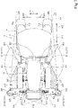
FIG. 1 is a plan view of a work vehicle. -
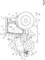
FIG. 2 is a side view of the work vehicle. -
FIG. 3 is a block diagram of a control system of the work vehicle. -
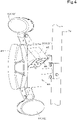
FIG. 4 is a perspective view illustrating a first obstacle detector. -
FIG. 5 is an exploded perspective front view illustrating a second obstacle detector. -
FIG. 6 is an explanatory diagram of a control method using a controller. -
FIG. 7 is a different explanatory diagram of the control method using the controller. - A preferred embodiment of the present invention is described below with reference to the drawings.
-
FIGs. 1 and2 each illustrate an embodiment of awork vehicle 1 according to the present invention. In the present embodiment, thework vehicle 1 is described as being atractor 1. However, thework vehicle 1 is not limited to a tractor and may be another type of work vehicle (agricultural vehicle), such as a combine or a rice-planting machine. - In the description below, a forward direction corresponds to a forward direction (in the direction of arrow A1) of an operator seated on a
driver seat 6 of thetractor 1, a rearward direction corresponds to a rearward direction (in the direction of arrow A2) of the operator, a leftward direction corresponds to a leftward direction (in the direction of arrow B 1) of the operator, and a rightward direction corresponds to a rightward direction (in the direction of arrow B2) of the operator. The directions of a double-headed arrow D are vehicle-width directions. A direction that is a vehicle-width direction and that is away from the center in the vehicle-width direction is a vehicle-width-direction outward direction, and a direction that is a vehicle-width direction and that is toward the center in the vehicle-width direction is a vehicle-width-direction inward direction. - As illustrated in
FIGs. 1 and2 , thetractor 1 includes avehicle body 2, atravel device 3, aprime mover 4, and atransmission 5. Thetravel device 3 supports thevehicle body 2 so that thevehicle body 2 can travel, and hasfront wheels 3F andrear wheels 3R. Although, in the present embodiment, thefront wheels 3F and therear wheels 3R are of a tire type, thefront wheels 3F and therear wheels 3R may be of a crawler type. - The
prime mover 4 is, for example, an engine (diesel engine or gasoline engine) or an electric motor. Thetransmission 5 can switch a thrust force of thetravel device 3 by changing the speed and can switch thetravel device 3 between forward travel and backward travel. - The
driver seat 6 is mounted on thevehicle body 2. A driver seatprotective body 7 is provided around thedriver seat 6. Although, in the present embodiment, the driver seatprotective body 7 is a cabin that protects thedriver seat 6 by surrounding a forward side, a rearward side, an upper side, and lateral sides of thedriver seat 6, the driver seatprotective body 7 may be, for example, a ROPS. In the description below, the driver seatprotective body 7 is described as acabin 7. Side surfaces (a left side surface and a right side surface) of thecabin 7 each have adoorway 8 through which an operator gets into and out of thecabin 7 and an entry/exit door 9 for opening and closing thedoorway 8. Entry/exit steps 17 on which an operator places his foot when the operator gets into and out of thecabin 7 are disposed below thecabin 7. Each entry/exit step 17 is provided below a corresponding one of the left and right entry/exit doors 9. Fenders 12 are mounted below thecabin 7. Eachfender 12 covers an upper portion of the corresponding therear wheel 3R. - A rear portion of the
vehicle body 2 is provided with a coupling portion (not illustrated) including, for example, a 3-point link mechanism. A work device (such as an implement) can be coupled to the coupling portion so as to be attachable and detachable to and from the coupling portion. By coupling the work device to the coupling portion, it is possible to pull the work device by thevehicle body 2. Examples of the work device include a cultivating device for cultivating, a fertilizer spraying device for spraying a fertilizer, an agrochemical spraying device for spraying an agrochemical, a harvesting device for harvesting, a cutting device for cutting grass or the like, a spreading device for spreading grass or the like, a grass collecting device for collecting grass or the like, and a shaping device for shaping grass or the like. - The
vehicle body 2 has a vehicle-body frame 10. The vehicle-body frame 10 extends forward from thetransmission 5 side, and supports a lower portion of theprime mover 4. As illustrated inFIG. 2 , ahood 13 is provided above the vehicle-body frame 10. Thehood 13 extends in a front-back direction along the vehicle-body frame 10. Thehood 13 is disposed forward of a central portion of thecabin 7 in the vehicle-width direction. Thehood 13 has aleft side wall 13L provided on the left side, aright side wall 13R provided on the right side, and anupper wall portion 13U that couples an upper portion of theleft side wall 13L and an upper portion of theright side wall 13R to each other. An engine compartment is formed by theleft side wall 13L, theright side wall 13R, and theupper wall portion 13U, and accommodates, for example, theprime mover 4, a cooling fan, a radiator, and a battery. Eachfront wheel 3F is disposed, one on a left lateral side of theleft side wall 13L and the other on a right lateral side of theright side wall 13R. - A
weight 14 is provided on a front side of thehood 13, that is, on a front side of the vehicle-body frame 10. Theweight 14 is attached to aweight bracket 15 provided on a front portion of thevehicle body 2. Theweight bracket 15 is attached to a front portion of the vehicle-body frame 10 by a fastener, such as a bolt. Aweight cover 16 covers theweight 14. - As illustrated in
FIG. 3 , thetractor 1 includes asteering device 11. Thesteering device 11 has asteering wheel 11a, a rotation shaft (steering shaft) 11b that rotates as thesteering wheel 11a is rotated, and an auxiliary mechanism (power steering mechanism) 11c that assists in the steering of thesteering wheel 11a. Theauxiliary mechanism 11c includes ahydraulic pump 21, acontrol valve 22 to which hydraulic fluid discharged from thehydraulic pump 21 is supplied, and asteering cylinder 23 that is operated by thecontrol valve 22. Thecontrol valve 22 is an electromagnetic valve that operates on the basis of a control signal. Thecontrol valve 22 is, for example, a 3-position switching valve that is switchable by the movement of a spool or the like. Thecontrol valve 22 is also switchable by steering thesteering shaft 11b. Thesteering cylinder 23 is connected to arms (knuckle arms) 24 that change the orientations of thefront wheels 3F. - Therefore, when the
steering wheel 11a is operated, a switching position and an opening degree of thecontrol valve 22 is switched in accordance with thesteering wheel 11a, and thesteering cylinder 23 extends or contracts leftward or rightward in accordance with the switching position and the opening degree of thecontrol valve 22 to thereby make it possible to change a steering direction of eachfront wheel 3F. Note that the above-describedsteering device 11 is one example, and the structure of thesteering device 11 is not limited to the above-described structure. - As illustrated in
FIGs. 1 and2 , thetractor 1 includes aposition detector 20. Theposition detector 20 is mounted forward of a top board of thecabin 7 via amount body 18. However, the mounting position of theposition detector 20 is not limited to the illustrated position, and theposition detector 20 may be mounted on the top board of thecabin 7 or may be mounted at a different location on thevehicle body 2. Theposition detector 20 may be attached to the above-described work device, such as a cultivating device. - The
position detector 20 is a device that detects a self position (position determination information including latitude and longitude) by a navigation satellite system. That is, theposition detector 20 receives a signal (for example, the position of a positioning satellite, transmission time, or correction information) transmitted from the positioning satellite, and detects the position (the latitude and the longitude) on the basis of the received signal. Theposition detector 20 may detect, as the self position (the latitude and the longitude), a position corrected on the basis of a signal of correction or the like from a base station (reference station) that is capable of receiving the signal from the positioning satellite. Alternatively, theposition detector 20 may have an inertial measurement device, such as a gyroscope sensor or an acceleration sensor, and detect, as the self position, a position corrected by the inertial measurement device. Theposition detector 20 is capable of detecting the position (travel position) of thevehicle body 2 of thetractor 1. The self position of thetractor 1 that is detected by theposition detector 20 may be, for example, the central position of thevehicle body 2, the position of at least onefront wheel 3F (for example, the position of its front end), or the position of at least onerear wheel 3R (for example, the position of its rear end), or may be the position of at least oneobstacle detector 31 described below. - As illustrated in
FIG. 3 , thetractor 1 includes acontroller 25. Thecontroller 25 includes, for example, electric circuits or electronic circuits, including a CPU, a storage unit (RAM, ROM, or the like), and the like, and performs various controls of thetractor 1 on the basis of, for example, a program stored in the storage unit. Astate detector 26 that detects, for example, a drive state of thetractor 1 is connected to thecontroller 25. Thestate detector 26 is, for example, a device that detects the state of a travel system, and detects the state of, for example, a crank sensor, a cam sensor, an engine rotation sensor, an axle sensor, a vehicle speed sensor, an acceleration sensor, a steering angle sensor, or theposition detector 20. Note that thestate detector 26 may be a device that detects states other than the state of the travel system, and may be, for example, a lifting lever detection sensor or a PTO rotation detection sensor. Alternatively, thetractor 1 may include a time measuring device that measures time and is capable of transmitting the measured time to thecontroller 25. - The
controller 25 controls the travel system and a work system of thetractor 1. For example, on the basis of a detection state detected by thestate detector 26, thecontroller 25 controls the engine speed, the vehicle speed, a steering angle of thesteering device 11, or the like. On the basis of a detection state detected by thestate detector 26, thestate detector 26 controls, for example, the raising and the lowering of a lifting device that raises and lowers the connection portion or a PTO rotation speed. - The
controller 25 can perform control of automatic travel (automatic travel control) of the tractor 1 (the vehicle body 2). Thecontroller 25 can perform switching between an automatic travel mode and a manual travel mode. In the automatic travel mode, thecontroller 25 causes thevehicle body 2 to perform automatic travel along a travel route set in advance. Thecontroller 25 sets a switching position and an opening degree of thecontrol valve 22 so as to cause at least a travel position of the vehicle body 2 (position detected by the position detector 20) and the travel route (travel path) set in advance to coincide with each other, that is, thevehicle body 2 and the travel route coincide with each other. In other words, in the automatic travel mode, thecontroller 25 sets a movement direction and a movement amount of the steering cylinder 23 (steering direction and steering angle of eachfront wheel 3F) so as to cause a travel position of thetractor 1 and the travel route to coincide with each other. - Specifically, in the automatic travel mode, the
controller 25 compares the travel position of thevehicle body 2 and a position indicated by the travel route (planned travel position), and, when the travel position and the planned travel position coincide with each other, a steering angle and a steering direction of thesteering wheel 11a of the steering device 11 (the steering angle and the steering direction of eachfront wheel 3F) are maintained without being changed (the opening degree and the switching position of thecontrol valve 22 are maintained without being changed). When the travel position and the planned travel position do not coincide with each other, thecontroller 25 changes the steering angle and/or the steering direction of thesteering wheel 11a of the steering device 11 (the opening degree and/or the switching position of the control valve 22) so as to cause a deviation (difference) between the travel position and the planned travel position to be zero. - Note that, in the above-described embodiment, although, in the automatic travel control, the
controller 25 changes the steering angle of thesteering device 11 on the basis of the deviation between the travel position and the planned travel position, when an orientation of the travel route and an orientation (vehicle body orientation) in a movement direction (travel direction) of the tractor 1 (the vehicle body 2) differ from each other, thecontroller 25 may set the steering angle so as to cause the vehicle body orientation to be the same as the orientation of the travel route. Alternatively, in the automatic travel control, thecontroller 25 may set a final steering angle in the automatic travel control on the basis of a steering angle obtained on the basis of a deviation (positional deviation) and a steering angle obtained on the basis of an orientation deviation. Alternatively, the steering angle may be set by a method differing from the method of setting the steering angle in the above-described automatic travel control. - Alternatively, in the automatic travel control, the
controller 25 may control the rotation speed of the travel device 3 (that is, thefront wheels 3F and/or therear wheels 3R) so as to cause the actual vehicle speed of the tractor 1 (the vehicle body 2) to be the same as a vehicle speed corresponding to the travel route set in advance. - The
transmission 5, a forward-reverse switching device 28, a PTO clutch 29, and abraking device 30 are connected to thecontroller 25. Thecontroller 25 is connected to thetransmission 5, the forward-reverse switching device 28, the PTO clutch 29, and thebraking device 30 via an in-vehicle LAN, such as CAN (Controller Area Network), or a communication line. Therefore, thecontroller 25 is capable of controlling the operations of thetransmission 5, the forward-reverse switching device 28, the PTO clutch 29, and thebraking device 30. - As illustrated in
FIGs. 1 to 3 , thetractor 1 includes the at least oneobstacle detector 31 that detects an obstacle, which hinders travelling. The at least oneobstacle detector 31 includes at least onefirst obstacle detector 31A and at least onesecond obstacle detector 31B. The at least onefirst obstacle detector 31A is a sonar that detects an obstacle by irradiation with a sound wave (ultrasonic wave) as a detection wave. The at least onesecond obstacle detector 31B is a laser scanner that detects an obstacle by irradiation with a light wave as a detection wave. However, the obstacle detectors may be sensors (distance measuring sensors) other than sonars and laser scanners. - The
controller 25 controls automatic travel on the basis of results of detections of obstacles by theobstacle detectors 31. For example, when theobstacle detectors 31 are not detecting an obstacle, the automatic travel is continued; and, when any one of theobstacle detectors 31 has detected an obstacle, the automatic travel is stopped. More specifically, when any one of theobstacle detectors 31 has detected an obstacle, if the distance between the obstacle and thetractor 1 is less than or equal to a predetermined distance, thecontroller 25 stops the automatic travel by stopping the travel of thetractor 1. - Specifically, when any one of the
obstacle detectors 31 has detected an obstacle, thecontroller 25 controls the operations of thetransmission 5, the forward-reverse switching device 28, the PTO clutch 29, and thebraking device 30. Specifically, thecontroller 25 reduces the vehicle speed by shift-down operating of thetransmission 5. Thecontroller 25 switches the forward-reverse switching device 28 to a neutral state, and causes thebraking device 30 to operate. Therefore, the automatic travel of thetractor 1 is stopped. Further, thecontroller 25 switches the PTO clutch 29 to an off state, and blocks transmission of power to a work device from a PTO shaft of thetractor 1. Thus, driving of the work device is stopped. - As illustrated in
FIG. 1 , the at least onefirst obstacle detector 31A is provided at a side portion of thecabin 7. Specifically, the at least onefirst obstacle detector 31A includes one at a left side portion of thecabin 7 and the other at a right side portion of thecabin 7. Thefirst obstacle detector 31A provided at the left side portion of thecabin 7 is positioned at the front left side of thecabin 7. Thefirst obstacle detector 31A provided at the right side portion of thecabin 7 is positioned at the front right side of thecabin 7. Thefirst obstacle detector 31A that is positioned on the front left side of thecabin 7 and thefirst obstacle detector 31A that is positioned on the front right side of thecabin 7 are symmetrically positioned on two sides of a central line of thetractor 1 in the vehicle-width direction. - The
first obstacle detectors 31A are disposed outward of thevehicle body 2 in the vehicle-width direction and between thefront wheels 3F and therear wheels 3R. More specifically, thefirst obstacle detectors 31A are disposed outward of thehood 13 in the vehicle-width direction and between thefront wheels 3F and therear wheels 3R. In the present embodiment, thefirst obstacle detector 31A that is positioned on the front left side of thecabin 7 is disposed forward of the left entry/exit step 17 and rearward of theleft front wheel 3F in the front-back direction. Thefirst obstacle detector 31A that is positioned on the front right side of thecabin 7 is disposed forward of the right entry/exit step 17 and rearward of theright front wheel 3F in the front-back direction. As illustrated inFIG. 2 , eachfirst obstacle detector 31A is disposed below an upper end portion of thehood 13 and above a lower end portion of thecabin 7. - As illustrated in
FIG. 1 , in the vehicle-width direction, eachfirst obstacle detector 31A is positioned between an end portion on an outer side in the vehicle-width direction (outer end portion) and an end portion on an inner side in the vehicle-width direction (inner end portion) of a corresponding one of thefront wheels 3F and between an end portion on an outer side in the vehicle-width direction (outer end portion) and an end portion on an inner side in the vehicle-width direction (inner end portion) of a corresponding one of therear wheels 3R. Eachfirst obstacle detector 31A can detect an obstacle existing outward of the correspondingfront wheel 3F in the vehicle-width direction. Eachfirst obstacle detector 31A can detect at least an obstacle existing between thecorresponding doorway 8 of thecabin 7 and the correspondingfront wheel 3F. - As illustrated in
FIGs. 2 and4 , eachfirst obstacle detector 31A is mounted on thecabin 7 via a corresponding mountingbracket 40.Combination lamps 41 andwork lamps 42 are also each mounted on thecabin 7 via a corresponding one of the mountingbrackets 40. A plurality of lamps that constitute thecombination lamps 41 are, for example, position lamps, blinker lamps, or hazard lamps. Thework lamps 42 include afront lamp 43 and aside illumination lamp 44. Each mountingbracket 40 is mounted on a corresponding one offront pillars 7a of thecabin 7. - Each mounting
bracket 40 is provided with adetector mounting portion 45. Eachdetector mounting portion 45 has aninclined plate 46 that extends upward toward an outer side in the vehicle-width direction. Eachinclined plate 46 has anopening 46a for transmission at which a transmission portion of the correspondingfirst obstacle detector 31A is disposed. A sound wave that is transmitted from eachfirst obstacle detector 31A passes through thecorresponding opening 46a for transmission and moves outward in the vehicle-width direction and downward. Therefore, thefirst obstacle detectors 31A are capable of detecting obstacles existing beside and below (lower right and lower left of) thevehicle body 2. - As illustrated in
FIGs. 1 and2 , the at least onesecond obstacle detector 31B is provided at a position differing from the positions of thefirst obstacle detectors 31A in the front-back direction. In the present embodiment, the at least onesecond obstacle detector 31B is provided forward of thefirst obstacle detectors 31A. The at least onesecond obstacle detector 31B is disposed forward of the correspondingfront wheel 3F. The at least onesecond obstacle detector 31B is disposed outward of the correspondingfront wheel 3F in the vehicle-width direction. The at least onesecond obstacle detector 31B is disposed outward of the correspondingrear wheel 3R in the vehicle-width direction. The at least onesecond obstacle detector 31B is disposed outward of the correspondingfirst obstacle detector 31A in the vehicle-width direction. - As illustrated in
FIG. 1 , the at least onesecond obstacle detector 31B includes one on the front left side of theleft front wheel 3F and the other on the front right side of theright front wheel 3F. Thesecond obstacle detector 31B disposed at the front left side of theleft front wheel 3F and thesecond obstacle detector 31B disposed on the front right side of theright front wheel 3F are symmetrically positioned on two sides of the central line of thetractor 1 in the vehicle-width direction. - Note that
second obstacle detectors 31B may be provided rearward of thefirst obstacle detectors 31A. In this case, thesecond obstacle detectors 31B are provided both forward of and rearward of thefirst obstacle detectors 31A. When thesecond obstacle detectors 31B are provided rearward of thefirst obstacle detectors 31A, for example, it is possible to dispose thesecond obstacle detectors 31B at rear portions of thecabin 7 or the like, and rearward of therear wheels 3R. - As illustrated in
FIGs. 1 and2 , eachsecond obstacle detector 31B is mounted on the vehicle-body frame 10 via a corresponding mountingstructural body 50. As illustrated inFIGs. 1 and5 , each mountingstructural body 50 has a firststructural body 51, a secondstructural body 52, a thirdstructural body 53, and a fourthstructural body 54. The firststructural bodies 51 are mounted on the vehicle-body frame 10, and extend forward and outward in the vehicle-width direction (toward the front left and the front right) from the vehicle-body frame 10. Each secondstructural body 52 is mounted on a front end (extension end) of the corresponding firststructural body 51. Each secondstructural body 52 has abase portion 52a mounted on the corresponding firststructural body 51, arotation shaft 52b provided at thebase portion 52a and extending in the front-back direction, and arotation portion 52c rotatable around therotation shaft 52b as a fulcrum. Each thirdstructural body 53 is mounted on thecorresponding rotation portion 52c and extends outward in the vehicle-width direction from thecorresponding rotation portion 52c. Each fourthstructural body 54 is mounted on an outer end portion in the vehicle-width direction of the corresponding thirdstructural body 53, and supports the correspondingsecond obstacle detector 31B.Sonars 55 that differ from the sonars that constitute thefirst obstacle detectors 31A are mounted on the thirdstructural bodies 53. - By rotating the third
structural body 53 of each mountingstructural body 50 upward around therotation shaft 52b as a fulcrum, the position of eachsecond obstacle detector 31B can be changed to a detection position (seeFIGs. 1 and2 ) for detecting an obstacle, and to a retraction position (not illustrated) at which the thirdstructural body 53 retracts toward thevehicle body 2 side from the detection position. Each mountingstructural body 50 is provided with ahandle 58 that can be grasped when changing the position of the correspondingsecond obstacle detector 31B. When eachsecond obstacle detector 31B is at the detection position, an emission direction of laser that is emitted from eachsecond obstacle detector 31B is a horizontal direction. - Each
second obstacle detector 31B is covered by a correspondingcover 56. Eachcover 56 is mounted on the corresponding thirdstructural body 53 byfasteners 57, such as bolts. Eachcover 56 includes anupper cover 56A disposed above the correspondingsecond obstacle detector 31B and alower cover 56B disposed below the correspondingsecond obstacle detector 31B. A gap G (seeFIG. 2 ) is formed between theupper cover 56A and thelower cover 56B around eachsecond obstacle detector 31B, and eachsecond obstacle detector 31B is capable of transmitting and receiving a detection wave (laser) via the corresponding gap G. Eachsonar 55 is capable of transmitting and receiving a detection wave (sound wave) via openings (cutout 56c andhole 56d) formed in the correspondingupper cover 56A. - In
FIG. 1 , a detection range of eachfirst obstacle detector 31A is denoted by symbol R1, and a detection range of eachsecond obstacle detector 31B is denoted by symbol R2. The detection range R1 of eachfirst obstacle detector 31A is a region having a fan shape in plan view and facing outward of the vehicle body from the correspondingfirst obstacle detector 31A. The detection range R2 of eachsecond obstacle detector 31B is a region situated outward of the vehicle body from a line La and forward of a line Lb. As illustrated inFIG. 1 , when thetractor 1 is stopped (before the start of automatic travel), non-detection ranges R3 that are not included in the detection ranges R1 of thefirst obstacle detectors 31A and the detection ranges R2 of thesecond obstacle detectors 31B exist beside the respectivefront wheels 3F (outward of the vehicle body). The non-detection ranges R3 exist for ensuring movable spaces of thefront wheels 3F at the time of a steering operation. - The
controller 25 performs control described below for detecting obstacles existing in the non-detection ranges R3. - At a time of start of automatic travel, the
controller 25 puts eachfirst obstacle detector 31A in a detection state of detecting an obstacle, and, during automatic travel after the start of the automatic travel, thecontroller 25 puts eachfirst obstacle detector 31A in a non-detection state of not detecting an obstacle. - In other words, within a predetermined time from the time of the start after the automatic travel, the
controller 25 puts eachfirst obstacle detector 31A in the detection state of detecting an obstacle, and, after the elapse of the predetermined time, thecontroller 25 puts eachfirst obstacle detector 31A in the non-detection state of not detecting an obstacle. - A time to a time at which the
controller 25 puts eachfirst obstacle detector 31A in the non-detection state during the automatic travel after the start of the automatic travel from the time of the start of the automatic travel (the aforementioned predetermined time) is preferably set to a time in which entire regions of the non-detection ranges R3 are covered by the detection ranges R1 of the respectivefirst obstacle detectors 31A (become detected regions) due to the movement of thetractor 1 after the start of the automatic travel. - For example, the time to the time at which the
controller 25 puts eachfirst obstacle detector 31A in the non-detection state during the automatic travel after the start of the automatic travel from the time of the start of the automatic travel (the aforementioned predetermined time) can be set to a time in which thefirst obstacle detectors 31A pass the positions of the wheels (thefront wheels 3F or therear wheels 3R; hereunder the same) or lateral positions of the wheels (right lateral positions or left lateral positions of the wheels; hereunder the same) before the start of the automatic travel. Control by thecontroller 25 when the time has been set in this way is described below. - In this case, after the start of the automatic travel, the
controller 25 puts eachfirst obstacle detector 31A in the detection state of detecting an obstacle until thefirst obstacle detectors 31A pass the positions of the wheels or the lateral positions of the wheels before the start of the automatic travel, and thecontroller 25 puts eachfirst obstacle detector 31A in the non-detection state of not detecting an obstacle after thefirst obstacle detectors 31A have passed the positions of the wheels or the lateral positions of the wheels before the start of the automatic travel. - When the
tractor 1 travels automatically toward the front (that is, moves forward), after the start of the automatic travel, thecontroller 25 puts eachfirst obstacle detector 31A in the detection state of detecting an obstacle until thefirst obstacle detectors 31A pass the positions of thefront wheels 3F or the lateral positions of thefront wheels 3F before the start of the automatic travel, and thecontroller 25 puts eachfirst obstacle detector 31A in the non-detection state of not detecting an obstacle after thefirst obstacle detectors 31A have passed the positions of thefront wheels 3F or the lateral positions of thefront wheels 3F before the start of the automatic travel. In this case, "until thefirst obstacle detectors 31A pass the positions of thefront wheels 3F or the lateral positions of thefront wheels 3F before the start of the automatic travel" can be restated as "until, in the front-back direction, thefirst obstacle detectors 31A move forward beyond the positions of front ends of thefront wheels 3F before the start of the automatic travel". - When the
tractor 1 travels automatically toward the back (that is, moves backward), after the start of the automatic travel, thecontroller 25 puts eachfirst obstacle detector 31A in the detection state of detecting an obstacle until thefirst obstacle detectors 31A pass the positions of therear wheels 3R or the lateral positions of therear wheels 3R before the start of the automatic travel, and thecontroller 25 puts eachfirst obstacle detector 31A in the non-detection state of not detecting an obstacle after thefirst obstacle detectors 31A have passed the positions of therear wheels 3R or the lateral positions of therear wheels 3R before the start of the automatic travel. In this case, "until thefirst obstacle detectors 31A pass the positions of therear wheels 3R or the lateral positions of therear wheels 3R before the start of the automatic travel" can be restated as "until, in the front-back direction, thefirst obstacle detectors 31A move backward beyond the positions of rear ends of therear wheels 3R before the start of the automatic travel". When this control is to be performed, thetractor 1 includessecond obstacle detectors 31B provided rearward of therear wheels 3R. - With reference to
FIG. 6 , the control by thecontroller 25 is described in detail below. Here, the case in which thetractor 1 moves forward due to automatic travel is described. Although the case in which thetractor 1 moves backward due to automatic travel is not illustrated, "moves forward" may be read as "moves backward", and "front wheels" may be read as "rear wheels" in the description below. -
FIG. 6(A) illustrates a switching operation between ON and OFF of eachfirst obstacle detector 31A by thecontroller 25. "ON" means that eachfirst obstacle detector 31A is in the detection state, and "OFF" means that eachfirst obstacle detector 31A is in the non-detection state.FIG. 6(B) illustrates the position of thetractor 1 at the start of the automatic travel.FIG. 6(C) illustrates the position of thetractor 1 after the start of the automatic travel and when, in the front-back direction, thefirst obstacle detectors 31A have reached the positions of the front ends of thefront wheels 3F before the start of the automatic travel. At this time, thetractor 1 moves forward by a distance L from the position of thetractor 1 before the start of the automatic travel. The distance L is a distance in the front-back direction between the front ends of thefront wheels 3F of thetractor 1 and the respectivefirst obstacle detectors 31A. - First, before the
tractor 1 starts the automatic travel (period T1), thecontroller 25 puts eachfirst obstacle detector 31A in the non-detection state (OFF). When thetractor 1 starts the automatic travel (time Ta), that is, when thetractor 1 starts to move forward due to the automatic travel from the position shown inFIG. 6(B) , thecontroller 25 puts eachfirst obstacle detector 31A in the detection state (ON). After thetractor 1 has started the automatic travel, until thefirst obstacle detectors 31A pass the positions of thefront wheels 3F (or the lateral positions of thefront wheels 3F) before the start of the automatic travel (period T2), that is, until thetractor 1 reaches the position illustrated inFIG. 6(C) , thecontroller 25 maintains the detection state (ON) of eachfirst obstacle detector 31A. Then, after thetractor 1 has passed the positions of thefront wheels 3F (or the lateral positions of thefront wheels 3F) (period T3), that is, after thetractor 1 has passed the position illustrated inFIG. 6(C) , thecontroller 25 puts eachfirst obstacle detector 31A in the non-detection state (OFF). -
FIG. 7 illustrates the relationship between the detection ranges R1 of thefirst obstacle detectors 31A and the non-detection ranges R3 before the start of the automatic travel of thetractor 1 when thecontroller 25 has performed the above-described control and thetractor 1 has automatically travelled.FIG. 7(A) illustrates a state at the start of the automatic travel of thetractor 1,FIG. 7(B) illustrates a state in which thetractor 1 has moved forward by a distance L1 (L1 < L) after the start of the automatic travel of thetractor 1, andFIG. 7(C) illustrates a state in which thetractor 1 has moved forward by the distance L after the start of the automatic travel of thetractor 1. InFIGs. 7(A) to 7(C) , of the non-detection ranges R3 before the start of the automatic travel of thetractor 1, each region (detected region R4) that has been detected by overlapping the detection range R1 of the correspondingfirst obstacle detector 31A is cross-hatched. - As illustrated in
FIG. 7 , due to thecontroller 25 performing the above-described control, eachfirst obstacle detector 31A that has been put in the detection state when thetractor 1 has started to move forward due to the automatic travel (seeFIG. 7(A) ) moves forward while being kept in the detection state (while having the corresponding detection range R1). Therefore, the detection ranges R1 of thefirst obstacle detectors 31A move forward while overlapping the respective non-detection ranges R3 and increasing the sizes of the respective detected regions R4 (seeFIG. 7(B) ), and the entire regions of the non-detection ranges R3 become the detected regions R4 (seeFIG. 7(C) ). As a result, obstacles can be detected in the entire regions of the non-detection ranges R3 by thefirst obstacle detectors 31A. - As described above, due to the
controller 25 performing the above-described control, even if obstacles exist in the non-detection ranges R3 not included in the detection ranges R1 of thefirst obstacle detectors 31A and in the detection ranges R2 of thesecond obstacle detectors 31B when thetractor 1 is stopped (before the start of automatic travel), the obstacles are capable of being detected by thesecond obstacle detectors 31B. As a result, when the tractor 1 (the vehicle body 2) starts to move due to the automatic travel, it is possible to prevent thevehicle body 2 or the like of thetractor 1 from coming into contact with the obstacles (human beings or things) existing in the non-detection ranges R3. - Due to the
controller 25 putting thefirst obstacle detectors 31A in the non-detection state after thefirst obstacle detectors 31A have passed the positions of thefront wheels 3F or the lateral positions of thefront wheels 3F before the automatic travel, thecontroller 25 is capable of preventing stoppage of the automatic travel caused by, for example, thefirst obstacle detectors 31A falsely detecting obstacles. Specifically, for example, it is possible to prevent stoppage of the automatic travel caused by thefirst obstacle detectors 31A falsely detecting as obstacles, for example, crops existing beside thevehicle body 2. - For example, by the following method, the
controller 25 is capable of determining that thefirst obstacle detectors 31A have passed the positions of the wheels or the lateral positions of the wheels before the start of automatic travel. However, the method of determining that thefirst obstacle detectors 31A have passed the positions of the wheels or the lateral positions of the wheels before the start of the automatic travel is not limited to the method described below. - On the basis of at least an elapsed time from the start of the automatic travel, the
controller 25 is capable of determining that the first obstacle detectors have passed the positions of the wheels or the lateral positions of the wheels before the start of the automatic travel. Specifically, on the basis of the elapsed time from the start of the automatic travel and the travel speed of thevehicle body 2, thecontroller 25 is capable of determining that thefirst obstacle detectors 31A have passed the positions of the wheels or the lateral positions of the wheels before the start of the automatic travel. In this case, on the basis of the distance L of thetractor 1, which is a known value, the travel speed of thetractor 1 detected by a vehicle speed sensor (the average travel speed while thetractor 1 moves forward by the distance L), and the elapsed time from the start of the automatic travel measured by a time measuring device, thecontroller 25 determines that thefirst obstacle detectors 31A have passed the positions of the wheels or the lateral positions of the wheels before the start of the automatic travel. For example, when the travel speed is V (m/s), the elapsed time is T(s), and the distance in the front-back direction between thefirst obstacle detectors 31A and the front ends of the respectivefront wheels 3F is L(m), and when the elapsed time T satisfies T > L/V, thecontroller 25 determines that thefirst obstacle detectors 31A have passed the positions of the wheels or the lateral positions of the wheels before the start of the automatic travel. - On the basis of the elapsed time from the start of the automatic travel and the acceleration of the
vehicle body 2, thecontroller 25 is also capable of determining that thefirst obstacle detectors 31A have passed the positions of the wheels or the lateral positions of the wheels before the start of the automatic travel. In this case, on the basis of the distance L of thetractor 1, which is a known value, the acceleration of thetractor 1 detected by an acceleration sensor (the average acceleration while thetractor 1 moves forward by the distance L), and the elapsed time from the start of the automatic travel measured by a time measuring device, thecontroller 25 is capable of determining that thefirst obstacle detectors 31A have passed the positions of the wheels or the lateral positions of the wheels before the start of the automatic travel. - On the basis of the position of the
vehicle body 2 detected by theposition detector 20, thecontroller 25 is also capable of determining that thefirst obstacle detectors 31A have passed the positions of the wheels or the lateral positions of the wheels before the start of the automatic travel. In this case, on the basis of the distance L of thetractor 1, which is a known value, a position P1 of thevehicle body 2 before the start of the automatic travel detected by theposition detector 20, and a position P2 of thevehicle body 2 after the start of the automatic travel detected by theposition detector 20, thecontroller 25 is capable of determining that thefirst obstacle detectors 31A have passed the positions of the wheels or the lateral positions of the wheels before the start of the automatic travel by comparing the distances at the position P1 and at the position P2 in the front-back direction with the distance L. - The
work vehicle 1 of the above-described embodiment provides the following effects. - The
work vehicle 1 includes avehicle body 2 having at least one wheel; acontroller 25 that causes thevehicle body 2 to perform automatic travel along a travel route set in advance; adriver seat 6 mounted on thevehicle body 2; a driver seatprotective body 7 provided around thedriver seat 6; at least onefirst obstacle detector 31A provided at a side portion of the driver seatprotective body 7, and capable of detecting an obstacle; and at least onesecond obstacle detector 31B provided at a position differing from a position of the at least onefirst obstacle detector 31A in a front-back direction, and capable of detecting an obstacle. At a time of start of the automatic travel, thecontroller 25 puts eachfirst obstacle detector 31A in a detection state of detecting an obstacle, and, during automatic travel after the start of the automatic travel, thecontroller 25 puts eachfirst obstacle detector 3 1A in a non-detection state of not detecting an obstacle. - According to this structure, since, at the time of the start of the automatic travel, the at least one
first obstacle detector 31 A is put in the detection state of detecting an obstacle, it is possible to prevent contact with an obstacle when thework vehicle 1 starts to move due to the automatic travel. Since, during the automatic travel after the start of the automatic travel, the at least onefirst obstacle detector 31A is put in the non-detection state of not detecting an obstacle, it is possible to prevent a false detection of an obstacle and realize smooth automatic travel. - After the start of the automatic travel, the
controller 25 puts eachfirst obstacle detector 3 1A in the detection state of detecting an obstacle until thefirst obstacle detector 31A passes a position of the at least one wheel or a lateral position of the at least one wheel before the start of the automatic travel, and the controller puts the at least onefirst obstacle detector 31A in the non-detection state of not detecting an obstacle after the at least onefirst obstacle detector 3 1 A has passed the position of the at least one wheel or the lateral position of the at least one wheel before the start of the automatic travel. - According to this structure, since, after the start of the automatic travel, the at least one
first obstacle detector 31A is put in the detection state until the at least onefirst obstacle detector 31A pass the position of the at least one wheel or the lateral position of the at least one wheel before the start of the automatic travel, an obstacle existing at, for example, a lateral region of the front wheel, which is a non-detection range of the obstacle detector before the start of the automatic travel, is capable of being detected by thefirst obstacle detector 31A after the start of the automatic travel. Therefore, it is possible to reliably prevent contact with an obstacle when thework vehicle 1 starts to move due to the automatic travel. - The at least one wheel includes at the least one
front wheel 3F provided at a front portion of thevehicle body 2 and arear wheel 3R provided at a rear portion of thevehicle body 2; the at least onesecond obstacle detector 31B is provided forward of the at least onefirst obstacle detector 31A; and, after the start of the automatic travel, thecontroller 25 puts the at least onefirst obstacle detector 31A in the detection state of detecting an obstacle until the at least onefirst obstacle detector 31A passes a position of the at least onefront wheel 3F or a lateral position of the at least onefront wheel 3F before the start of the automatic travel, and thecontroller 25 puts the at least onefirst obstacle detector 31A in the non-detection state of not detecting an obstacle after the at least onefirst obstacle detector 31A has passed the position of the at least onefront wheel 3F or the lateral position of the at least onefront wheel 3F before the start of the automatic travel. - According to this structure, when the
work vehicle 1 moves forward due to the automatic travel, it is possible to prevent contact with an obstacle when thework vehicle 1 starts to move due to the automatic travel, and prevent a false detection of an obstacle and realize smooth automatic travel. - On the basis of at least an elapsed time from the start of the automatic travel, the
controller 25 determines that the at least onefirst obstacle detector 31A has passed the position of the at least one wheel or the lateral position of the at least one wheel before the start of the automatic travel. - According to this structure, it is possible to, on the basis of, for example, the elapsed time from the start of the automatic travel, easily determine that the at least one
first obstacle detector 31A has passed the position of the at least one wheel or the lateral position of the at least one wheel before the start of the automatic travel. - On the basis of an elapsed time from the start of the automatic travel and a travel speed of the
vehicle body 2, thecontroller 25 determines that the at least onefirst obstacle detector 31A has passed the position of the at least one wheel or the lateral position of the at least one wheel before the start of the automatic travel. - According to this structure, it is possible to, on the basis of the elapsed time from the start of the automatic travel and the travel speed of the
vehicle body 2, easily and reliably determine that the at least onefirst obstacle detector 31A has passed the position of the at least one wheel or the lateral position of the at least one wheel before the start of the automatic travel. - On the basis of an elapsed time from the start of the automatic travel and an acceleration of the
vehicle body 2, thecontroller 25 determines that the at least onefirst obstacle detector 31A has passed the position of the at least one wheel or the lateral position of the at least one wheel before the start of the automatic travel. - According to this structure, it is possible to, on the basis of the elapsed time from the start of the automatic travel and the acceleration of the
vehicle body 2, easily and reliably determine that the at least onefirst obstacle detector 31A has passed the position of the at least one wheel or the lateral position of the at least one wheel before the start of the automatic travel. - The
work vehicle 1 includes aposition detector 20 that detects a position of thevehicle body 2, and, on the basis of the position of thevehicle body 2 detected by theposition detector 20, thecontroller 25 determines that the at least onefirst obstacle detector 31A has passed the position of the at least one wheel or the lateral position of the at least one wheel before the start of the automatic travel. - According to this structure, it is possible to, on the basis of the position of the
vehicle body 2 detected by theposition detector 20, easily and reliably determine that the at least onefirst obstacle detector 31A has passed the position of the at least one wheel or the lateral position of the at least one wheel before the start of the automatic travel. - The at least one
second obstacle detector 31B is disposed forward of the at least onefront wheel 3F, and the at least onefirst obstacle detector 31A is disposed between the at least onefront wheel 3F and the at least onerear wheel 3R so as to be capable of detecting an obstacle outward of the at least onefront wheel 3F in a vehicle-width direction. - According to this structure, it is possible to prevent contact with an obstacle when the
work vehicle 1 starts to move due to the automatic travel, while reliably detecting an obstacle existing in front of the at least onefront wheel 3F by the at least onesecond obstacle detector 31B and reliably detecting an obstacle existing between the at least onefront wheel 3F and the at least onerear wheel 3R and outward of the at least onefront wheel 3F in the vehicle-width direction by the at least onefirst obstacle detector 31A. - The at least one
second obstacle detector 31B is disposed outward of the at least onefront wheel 3F in a vehicle-width direction, and the at least onefirst obstacle detector 31A is disposed inward of the at least onesecond obstacle detector 31B in the vehicle-width direction. - According to this structure, it is possible to prevent contact with an obstacle when the
work vehicle 1 starts to move due to the automatic travel, while reliably detecting obstacles existing outward of the at least onefront wheel 3F in the vehicle-width direction by the at least onesecond obstacle detector 31B and reliably detecting an obstacle existing inward of the at least onesecond obstacle detector 31B in the vehicle-width direction by the at least onefirst obstacle detector 31A. - The driver seat
protective body 7 is acabin 7 mounted on thevehicle body 2, and the at least onefirst obstacle detector 31A is capable of detecting an obstacle between adoorway 8 of thecabin 7 and the at least onefront wheel 3F. - According to this structure, since an obstacle existing between the
doorway 8 of thecabin 7 and the at least onefront wheel 3F is capable of being detected by the at least onefirst obstacle detector 31A, after thework vehicle 1 has started the automatic travel, it is possible to prevent contact with the obstacles existing between thedoorway 8 and the at least onefront wheel 3F before the start of the automatic travel. - The at least one
first obstacle detector 31A is a sonar that detects an obstacle by irradiation with a sound wave as a detection wave, and the at least onesecond obstacle detector 31B is a laser scanner that detects an obstacle by irradiation with a laser as a detection wave. - According to this structure, it is possible to reliably detect an obstacle existing beside the driver seat
protective body 7 by the at least onefirst obstacle detector 31A, and it is possible to detect an obstacle existing in a wide range around (for example, in front of) thework vehicle 1 by the at least onesecond obstacle detector 31B. - Although the embodiment of the present invention has been described above, it should be considered that the embodiment disclosed herein is illustrative and not restrictive in all aspects. The scope of the present invention is defined not by the above description but by the claims, and is intended to include meaning equivalent to the claims and all modifications within the scope.
-
- 1
- work vehicle
- 2
- vehicle body
- 3F
- front wheel
- 3R
- rear wheel
- 25
- controller
- 6
- driver seat
- 7
- driver seat protective body (cabin)
- 8
- doorway
- 10
- vehicle-body frame
- 13
- hood
- 20
- position detector
- 31A
- first obstacle detector
- 31B
- second obstacle detector
Claims (15)
- A work vehicle comprising:a vehicle body having a wheel;a controller that causes the vehicle body to perform automatic travel along a travel route set in advance;a driver seat mounted on the vehicle body;a driver seat protective body provided around the driver seat;a first obstacle detector provided at a side portion of the driver seat protective body, and capable of detecting an obstacle; anda second obstacle detector provided at a position differing from a position of the first obstacle detector in a front-back direction, and capable of detecting the obstacle,wherein, at a time of start of the automatic travel, the controller puts the first obstacle detector in a detection state of detecting the obstacle, and, during automatic travel after the start of the automatic travel, the controller puts the first obstacle detector in a non-detection state of not detecting the obstacle.
- The work vehicle according to claim 1, wherein, after the start of the automatic travel, the controller puts the first obstacle detector in the detection state of detecting the obstacle until the first obstacle detector passes a position of the wheel or a lateral position of the wheel before the start of the automatic travel, and the controller puts the first obstacle detector in the non-detection state of not detecting the obstacle after the first obstacle detector has passed the position of the wheel or the lateral position of the wheel before the start of the automatic travel.
- The work vehicle according to claim 2, wherein the wheel includes a front wheel provided at a front portion of the vehicle body and a rear wheel provided at a rear portion of the vehicle body,wherein the second obstacle detector is provided forward of the first obstacle detector, andwherein, after the start of the automatic travel, the controller puts the first obstacle detector in the detection state until the first obstacle detector passes a position of the front wheel or a lateral position of the front wheel before the start of the automatic travel, and the controller puts the first obstacle detector in the non-detection state after the first obstacle detector has passed the position of the front wheel or the lateral position of the front wheel before the start of the automatic travel.
- The work vehicle according to claim 2 or claim 3, wherein, on the basis of at least an elapsed time from the start of the automatic travel, the controller determines that the first obstacle detector has passed the position of the wheel or the lateral position of the wheel before the start of the automatic travel.
- The work vehicle according to claim 2 or claim 3, wherein, on the basis of an elapsed time from the start of the automatic travel and a travel speed of the vehicle body, the controller determines that the first obstacle detector has passed the position of the wheel or the lateral position of the wheel before the start of the automatic travel.
- The work vehicle according to claim 2 or claim 3, wherein, on the basis of an elapsed time from the start of the automatic travel and an acceleration of the vehicle body, the controller determines that the first obstacle detector has passed the position of the wheel or the lateral position of the wheel before the start of the automatic travel.
- The work vehicle according to claim 2 or claim 3, comprising:a position detector that detects a position of the vehicle body,wherein, on the basis of the position of the vehicle body detected by the position detector, the controller determines that the first obstacle detector has passed the position of the wheel or the lateral position of the wheel before the start of the automatic travel.
- The work vehicle according to claim 3, wherein the second obstacle detector is disposed forward of the front wheel, and
wherein the first obstacle detector is disposed between the front wheel and the rear wheel so as to be capable of detecting an obstacle outward of the front wheel in a vehicle-width direction. - The work vehicle according to claim 3, wherein the second obstacle detector is disposed outward of the front wheel in a vehicle-width direction, and
wherein the first obstacle detector is disposed inward of the second obstacle detector in the vehicle-width direction. - The work vehicle according to any one of claims 1 to 9, wherein the driver seat protective body is a cabin mounted on the vehicle body, and
wherein the first obstacle detector is capable of detecting an obstacle between a doorway of the cabin and the front wheel. - The work vehicle according to any one of claims 1 to 10, wherein the first obstacle detector is a sonar that detects an obstacle by irradiation with a sound wave as a detection wave, and
wherein the second obstacle detector is a laser scanner that detects an obstacle by irradiation with a laser as a detection wave. - The work vehicle according to any one of claims 1 to 11, wherein a time from the time of the start of the automatic travel to a time at which the first obstacle detector is put in the non-detection state during the automatic travel after the start of the automatic travel is set to a time in which an entire region of a non-detection range not included in a detection range of the first obstacle detector and not included in a detection range of the second obstacle detector before the start of the automatic travel is covered by the detection range of the first obstacle detector due to a movement after the start of the automatic travel.
- The work vehicle according to any one of claims 3, 8, and 9, wherein the vehicle body has a vehicle-body frame,wherein a hood is provided above the vehicle-body frame, andwherein the first obstacle detector is disposed outward of the hood in a vehicle-width direction and between the front wheel and the rear wheel.
- The work vehicle according to claim 10, wherein the vehicle body has a vehicle-body frame,wherein a hood is provided above the vehicle-body frame, andwherein the first obstacle detector is disposed below an upper end portion of the hood and above a lower end portion of the cabin.
- The work vehicle according to any one of claims 3, 8, 9, and 13, wherein the front wheel includes a left front wheel and a right front wheel, and
wherein the second obstacle detector is disposed on each of a front left side of the left front wheel and a front right side of the right front wheel.
Applications Claiming Priority (2)
| Application Number | Priority Date | Filing Date | Title |
|---|---|---|---|
| JP2019228670A JP7258737B2 (en) | 2019-12-18 | 2019-12-18 | work vehicle |
| PCT/JP2020/046359 WO2021125096A1 (en) | 2019-12-18 | 2020-12-11 | Work vehicle |
Publications (3)
| Publication Number | Publication Date |
|---|---|
| EP4080308A1 true EP4080308A1 (en) | 2022-10-26 |
| EP4080308A4 EP4080308A4 (en) | 2023-11-29 |
| EP4080308B1 EP4080308B1 (en) | 2024-11-06 |
Family
ID=76431434
Family Applications (1)
| Application Number | Title | Priority Date | Filing Date |
|---|---|---|---|
| EP20901628.6A Active EP4080308B1 (en) | 2019-12-18 | 2020-12-11 | Work vehicle |
Country Status (6)
| Country | Link |
|---|---|
| US (1) | US12124264B2 (en) |
| EP (1) | EP4080308B1 (en) |
| JP (1) | JP7258737B2 (en) |
| KR (1) | KR20220116433A (en) |
| AU (1) | AU2020409138B2 (en) |
| WO (1) | WO2021125096A1 (en) |
Families Citing this family (5)
| Publication number | Priority date | Publication date | Assignee | Title |
|---|---|---|---|---|
| JP7159083B2 (en) * | 2019-03-06 | 2022-10-24 | 株式会社クボタ | work vehicle |
| JP7826817B2 (en) * | 2022-04-08 | 2026-03-10 | 株式会社豊田自動織機 | Obstacle detection device and driving control device |
| JP7788980B2 (en) * | 2022-09-26 | 2025-12-19 | 株式会社クボタ | Work vehicle |
| DE102022124886A1 (en) * | 2022-09-28 | 2024-03-28 | Valeo Schalter Und Sensoren Gmbh | SENSOR ARRANGEMENT HAVING AN ULTRASONIC TRANSCEIVER AND AN OPTICAL TRANSCEIVER DEVICE |
| JP2024130768A (en) * | 2023-03-15 | 2024-09-30 | 株式会社豊田自動織機 | Unmanned Vehicles |
Family Cites Families (28)
| Publication number | Priority date | Publication date | Assignee | Title |
|---|---|---|---|---|
| US8751103B2 (en) * | 2010-11-22 | 2014-06-10 | Caterpillar Inc. | Object detection system having interference avoidance strategy |
| US8744693B2 (en) * | 2010-11-22 | 2014-06-03 | Caterpillar Inc. | Object detection system having adjustable focus |
| JP5587499B2 (en) * | 2011-06-07 | 2014-09-10 | 株式会社小松製作所 | Work vehicle perimeter monitoring device |
| WO2015118731A1 (en) * | 2014-02-06 | 2015-08-13 | ヤンマー株式会社 | Control device for parallel travel work system |
| US9763377B2 (en) * | 2014-05-22 | 2017-09-19 | Yanmar Co., Ltd. | Running system of work vehicle |
| WO2016002623A1 (en) * | 2014-06-30 | 2016-01-07 | ヤンマー株式会社 | Parallel travel work system |
| US9740202B2 (en) * | 2016-01-08 | 2017-08-22 | Waymo Llc | Fall back trajectory systems for autonomous vehicles |
| US10077007B2 (en) * | 2016-03-14 | 2018-09-18 | Uber Technologies, Inc. | Sidepod stereo camera system for an autonomous vehicle |
| WO2018135256A1 (en) * | 2017-01-20 | 2018-07-26 | 株式会社クボタ | Work vehicle |
| WO2018135201A1 (en) * | 2017-01-20 | 2018-07-26 | 株式会社クボタ | Work vehicle |
| KR102472090B1 (en) * | 2017-01-20 | 2022-12-01 | 가부시끼 가이샤 구보다 | work car |
| EP3226553B1 (en) * | 2017-02-09 | 2018-12-12 | Komatsu Ltd. | Work vehicle periphery monitoring system, work vehicle, and work vehicle periphery monitoring method |
| US10477764B2 (en) * | 2017-03-28 | 2019-11-19 | Macdon Industries Ltd. | Crop harvesting machine including retractable sensor fingers with adjustable ground pressure and header tilt control |
| US10479354B2 (en) * | 2017-05-02 | 2019-11-19 | Cnh Industrial America Llc | Obstacle detection system for a work vehicle |
| US10583832B2 (en) * | 2017-05-02 | 2020-03-10 | Cnh Industrial America Llc | Obstacle detection system for a work vehicle |
| JP6945399B2 (en) * | 2017-09-13 | 2021-10-06 | 株式会社クボタ | Obstacle detector |
| JP6919531B2 (en) * | 2017-11-30 | 2021-08-18 | 井関農機株式会社 | Work vehicle |
| JP6962166B2 (en) * | 2017-12-11 | 2021-11-05 | 井関農機株式会社 | Remote control system for work vehicles |
| JP6850760B2 (en) * | 2018-03-28 | 2021-03-31 | ヤンマーパワーテクノロジー株式会社 | Automatic traveling device for work vehicles |
| JP6942664B2 (en) | 2018-03-28 | 2021-09-29 | ヤンマーパワーテクノロジー株式会社 | Travel control system for work vehicles |
| KR102734244B1 (en) * | 2018-03-28 | 2024-11-25 | 얀마 파워 테크놀로지 가부시키가이샤 | Driving control system of work vehicle |
| KR102800559B1 (en) * | 2018-03-29 | 2025-04-24 | 얀마 파워 테크놀로지 가부시키가이샤 | Obstacle detection system and work vehicle |
| JP2019174344A (en) * | 2018-03-29 | 2019-10-10 | ヤンマー株式会社 | Working vehicle-purpose obstacle detection system |
| US20190302783A1 (en) * | 2018-03-29 | 2019-10-03 | Autonomous Solutions, Inc. | System and method for autonomous work vehicle operations |
| JP7233950B2 (en) * | 2019-02-14 | 2023-03-07 | 株式会社クボタ | Agricultural machines |
| JP2020194253A (en) * | 2019-05-27 | 2020-12-03 | ヤンマーパワーテクノロジー株式会社 | Obstacle judgment system and autonomous driving system |
| JP7657542B2 (en) * | 2019-10-18 | 2025-04-07 | ヤンマーパワーテクノロジー株式会社 | Obstacle Detection System |
| JP7826817B2 (en) * | 2022-04-08 | 2026-03-10 | 株式会社豊田自動織機 | Obstacle detection device and driving control device |
-
2019
- 2019-12-18 JP JP2019228670A patent/JP7258737B2/en active Active
-
2020
- 2020-12-11 WO PCT/JP2020/046359 patent/WO2021125096A1/en not_active Ceased
- 2020-12-11 AU AU2020409138A patent/AU2020409138B2/en active Active
- 2020-12-11 EP EP20901628.6A patent/EP4080308B1/en active Active
- 2020-12-11 KR KR1020227016681A patent/KR20220116433A/en active Pending
-
2022
- 2022-05-17 US US17/746,108 patent/US12124264B2/en active Active
Also Published As
| Publication number | Publication date |
|---|---|
| KR20220116433A (en) | 2022-08-23 |
| JP2021096721A (en) | 2021-06-24 |
| AU2020409138B2 (en) | 2026-03-19 |
| US12124264B2 (en) | 2024-10-22 |
| JP7258737B2 (en) | 2023-04-17 |
| AU2020409138A1 (en) | 2022-05-26 |
| EP4080308A4 (en) | 2023-11-29 |
| US20220276656A1 (en) | 2022-09-01 |
| WO2021125096A1 (en) | 2021-06-24 |
| EP4080308B1 (en) | 2024-11-06 |
Similar Documents
| Publication | Publication Date | Title |
|---|---|---|
| EP4080308B1 (en) | Work vehicle | |
| JP6742928B2 (en) | Work vehicle | |
| WO2018135256A1 (en) | Work vehicle | |
| WO2018135234A1 (en) | Work vehicle | |
| EP3925424B1 (en) | Agricultural machine | |
| EP3925425B1 (en) | Agricultural machinery | |
| JP7547044B2 (en) | Work vehicles | |
| JP7440376B2 (en) | work vehicle | |
| JP2018114923A (en) | Work vehicle | |
| US11897381B2 (en) | Working vehicle | |
| JP6781056B2 (en) | Work vehicle | |
| JP7617836B2 (en) | Paddy field farming machine | |
| JP6991285B2 (en) | Work platform | |
| JP7094338B2 (en) | Work vehicle | |
| JP7058679B2 (en) | Work vehicle | |
| JP7094337B2 (en) | Work vehicle | |
| JP2022165450A (en) | work vehicle | |
| JP6832716B2 (en) | Work vehicle |
Legal Events
| Date | Code | Title | Description |
|---|---|---|---|
| STAA | Information on the status of an ep patent application or granted ep patent |
Free format text: STATUS: THE INTERNATIONAL PUBLICATION HAS BEEN MADE |
|
| PUAI | Public reference made under article 153(3) epc to a published international application that has entered the european phase |
Free format text: ORIGINAL CODE: 0009012 |
|
| STAA | Information on the status of an ep patent application or granted ep patent |
Free format text: STATUS: REQUEST FOR EXAMINATION WAS MADE |
|
| 17P | Request for examination filed |
Effective date: 20220428 |
|
| AK | Designated contracting states |
Kind code of ref document: A1 Designated state(s): AL AT BE BG CH CY CZ DE DK EE ES FI FR GB GR HR HU IE IS IT LI LT LU LV MC MK MT NL NO PL PT RO RS SE SI SK SM TR |
|
| DAV | Request for validation of the european patent (deleted) | ||
| DAX | Request for extension of the european patent (deleted) | ||
| A4 | Supplementary search report drawn up and despatched |
Effective date: 20231102 |
|
| RIC1 | Information provided on ipc code assigned before grant |
Ipc: A01B 69/04 20060101ALI20231026BHEP Ipc: G01S 17/931 20200101ALI20231026BHEP Ipc: G01S 17/88 20060101ALI20231026BHEP Ipc: G01S 17/42 20060101ALI20231026BHEP Ipc: G01S 15/931 20200101ALI20231026BHEP Ipc: G01S 15/88 20060101ALI20231026BHEP Ipc: G01S 15/86 20200101ALI20231026BHEP Ipc: B62D 49/06 20060101ALI20231026BHEP Ipc: B62D 33/06 20060101ALI20231026BHEP Ipc: G05D 1/02 20200101AFI20231026BHEP |
|
| REG | Reference to a national code |
Ref legal event code: R079 Ipc: G05D0001000000 Ref country code: DE Ref legal event code: R079 Ref document number: 602020041084 Country of ref document: DE Free format text: PREVIOUS MAIN CLASS: G05D0001020000 Ipc: G05D0001000000 |
|
| GRAP | Despatch of communication of intention to grant a patent |
Free format text: ORIGINAL CODE: EPIDOSNIGR1 |
|
| STAA | Information on the status of an ep patent application or granted ep patent |
Free format text: STATUS: GRANT OF PATENT IS INTENDED |
|
| RIC1 | Information provided on ipc code assigned before grant |
Ipc: A01B 69/04 20060101ALI20240604BHEP Ipc: G01S 17/42 20060101ALI20240604BHEP Ipc: G01S 15/931 20200101ALI20240604BHEP Ipc: G01S 15/88 20060101ALI20240604BHEP Ipc: G01S 15/86 20200101ALI20240604BHEP Ipc: B62D 49/06 20060101ALI20240604BHEP Ipc: B62D 33/06 20060101ALI20240604BHEP Ipc: G05D 1/00 20060101AFI20240604BHEP |
|
| INTG | Intention to grant announced |
Effective date: 20240628 |
|
| GRAS | Grant fee paid |
Free format text: ORIGINAL CODE: EPIDOSNIGR3 |
|
| GRAA | (expected) grant |
Free format text: ORIGINAL CODE: 0009210 |
|
| STAA | Information on the status of an ep patent application or granted ep patent |
Free format text: STATUS: THE PATENT HAS BEEN GRANTED |
|
| AK | Designated contracting states |
Kind code of ref document: B1 Designated state(s): AL AT BE BG CH CY CZ DE DK EE ES FI FR GB GR HR HU IE IS IT LI LT LU LV MC MK MT NL NO PL PT RO RS SE SI SK SM TR |
|
| REG | Reference to a national code |
Ref country code: GB Ref legal event code: FG4D |
|
| REG | Reference to a national code |
Ref country code: CH Ref legal event code: EP |
|
| REG | Reference to a national code |
Ref country code: DE Ref legal event code: R096 Ref document number: 602020041084 Country of ref document: DE |
|
| REG | Reference to a national code |
Ref country code: IE Ref legal event code: FG4D |
|
| REG | Reference to a national code |
Ref country code: LT Ref legal event code: MG9D |
|
| REG | Reference to a national code |
Ref country code: NL Ref legal event code: MP Effective date: 20241106 |
|
| PG25 | Lapsed in a contracting state [announced via postgrant information from national office to epo] |
Ref country code: IS Free format text: LAPSE BECAUSE OF FAILURE TO SUBMIT A TRANSLATION OF THE DESCRIPTION OR TO PAY THE FEE WITHIN THE PRESCRIBED TIME-LIMIT Effective date: 20250306 Ref country code: HR Free format text: LAPSE BECAUSE OF FAILURE TO SUBMIT A TRANSLATION OF THE DESCRIPTION OR TO PAY THE FEE WITHIN THE PRESCRIBED TIME-LIMIT Effective date: 20241106 Ref country code: PT Free format text: LAPSE BECAUSE OF FAILURE TO SUBMIT A TRANSLATION OF THE DESCRIPTION OR TO PAY THE FEE WITHIN THE PRESCRIBED TIME-LIMIT Effective date: 20250306 |
|
| PG25 | Lapsed in a contracting state [announced via postgrant information from national office to epo] |
Ref country code: FI Free format text: LAPSE BECAUSE OF FAILURE TO SUBMIT A TRANSLATION OF THE DESCRIPTION OR TO PAY THE FEE WITHIN THE PRESCRIBED TIME-LIMIT Effective date: 20241106 Ref country code: NL Free format text: LAPSE BECAUSE OF FAILURE TO SUBMIT A TRANSLATION OF THE DESCRIPTION OR TO PAY THE FEE WITHIN THE PRESCRIBED TIME-LIMIT Effective date: 20241106 |
|
| REG | Reference to a national code |
Ref country code: AT Ref legal event code: MK05 Ref document number: 1740050 Country of ref document: AT Kind code of ref document: T Effective date: 20241106 |
|
| PG25 | Lapsed in a contracting state [announced via postgrant information from national office to epo] |
Ref country code: BG Free format text: LAPSE BECAUSE OF FAILURE TO SUBMIT A TRANSLATION OF THE DESCRIPTION OR TO PAY THE FEE WITHIN THE PRESCRIBED TIME-LIMIT Effective date: 20241106 |
|
| PG25 | Lapsed in a contracting state [announced via postgrant information from national office to epo] |
Ref country code: ES Free format text: LAPSE BECAUSE OF FAILURE TO SUBMIT A TRANSLATION OF THE DESCRIPTION OR TO PAY THE FEE WITHIN THE PRESCRIBED TIME-LIMIT Effective date: 20241106 |
|
| PG25 | Lapsed in a contracting state [announced via postgrant information from national office to epo] |
Ref country code: NO Free format text: LAPSE BECAUSE OF FAILURE TO SUBMIT A TRANSLATION OF THE DESCRIPTION OR TO PAY THE FEE WITHIN THE PRESCRIBED TIME-LIMIT Effective date: 20250206 |
|
| PG25 | Lapsed in a contracting state [announced via postgrant information from national office to epo] |
Ref country code: GR Free format text: LAPSE BECAUSE OF FAILURE TO SUBMIT A TRANSLATION OF THE DESCRIPTION OR TO PAY THE FEE WITHIN THE PRESCRIBED TIME-LIMIT Effective date: 20250207 Ref country code: AT Free format text: LAPSE BECAUSE OF FAILURE TO SUBMIT A TRANSLATION OF THE DESCRIPTION OR TO PAY THE FEE WITHIN THE PRESCRIBED TIME-LIMIT Effective date: 20241106 Ref country code: LV Free format text: LAPSE BECAUSE OF FAILURE TO SUBMIT A TRANSLATION OF THE DESCRIPTION OR TO PAY THE FEE WITHIN THE PRESCRIBED TIME-LIMIT Effective date: 20241106 |
|
| PG25 | Lapsed in a contracting state [announced via postgrant information from national office to epo] |
Ref country code: PL Free format text: LAPSE BECAUSE OF FAILURE TO SUBMIT A TRANSLATION OF THE DESCRIPTION OR TO PAY THE FEE WITHIN THE PRESCRIBED TIME-LIMIT Effective date: 20241106 |
|
| PG25 | Lapsed in a contracting state [announced via postgrant information from national office to epo] |
Ref country code: RS Free format text: LAPSE BECAUSE OF FAILURE TO SUBMIT A TRANSLATION OF THE DESCRIPTION OR TO PAY THE FEE WITHIN THE PRESCRIBED TIME-LIMIT Effective date: 20250206 |
|
| PG25 | Lapsed in a contracting state [announced via postgrant information from national office to epo] |
Ref country code: SM Free format text: LAPSE BECAUSE OF FAILURE TO SUBMIT A TRANSLATION OF THE DESCRIPTION OR TO PAY THE FEE WITHIN THE PRESCRIBED TIME-LIMIT Effective date: 20241106 |
|
| PG25 | Lapsed in a contracting state [announced via postgrant information from national office to epo] |
Ref country code: DK Free format text: LAPSE BECAUSE OF FAILURE TO SUBMIT A TRANSLATION OF THE DESCRIPTION OR TO PAY THE FEE WITHIN THE PRESCRIBED TIME-LIMIT Effective date: 20241106 |
|
| PG25 | Lapsed in a contracting state [announced via postgrant information from national office to epo] |
Ref country code: EE Free format text: LAPSE BECAUSE OF FAILURE TO SUBMIT A TRANSLATION OF THE DESCRIPTION OR TO PAY THE FEE WITHIN THE PRESCRIBED TIME-LIMIT Effective date: 20241106 |
|
| PG25 | Lapsed in a contracting state [announced via postgrant information from national office to epo] |
Ref country code: RO Free format text: LAPSE BECAUSE OF FAILURE TO SUBMIT A TRANSLATION OF THE DESCRIPTION OR TO PAY THE FEE WITHIN THE PRESCRIBED TIME-LIMIT Effective date: 20241106 |
|
| PG25 | Lapsed in a contracting state [announced via postgrant information from national office to epo] |
Ref country code: SK Free format text: LAPSE BECAUSE OF FAILURE TO SUBMIT A TRANSLATION OF THE DESCRIPTION OR TO PAY THE FEE WITHIN THE PRESCRIBED TIME-LIMIT Effective date: 20241106 |
|
| PG25 | Lapsed in a contracting state [announced via postgrant information from national office to epo] |
Ref country code: CZ Free format text: LAPSE BECAUSE OF FAILURE TO SUBMIT A TRANSLATION OF THE DESCRIPTION OR TO PAY THE FEE WITHIN THE PRESCRIBED TIME-LIMIT Effective date: 20241106 |
|
| PG25 | Lapsed in a contracting state [announced via postgrant information from national office to epo] |
Ref country code: IT Free format text: LAPSE BECAUSE OF FAILURE TO SUBMIT A TRANSLATION OF THE DESCRIPTION OR TO PAY THE FEE WITHIN THE PRESCRIBED TIME-LIMIT Effective date: 20241106 |
|
| REG | Reference to a national code |
Ref country code: CH Ref legal event code: PL |
|
| REG | Reference to a national code |
Ref country code: DE Ref legal event code: R097 Ref document number: 602020041084 Country of ref document: DE |
|
| PG25 | Lapsed in a contracting state [announced via postgrant information from national office to epo] |
Ref country code: LU Free format text: LAPSE BECAUSE OF NON-PAYMENT OF DUE FEES Effective date: 20241211 |
|
| PG25 | Lapsed in a contracting state [announced via postgrant information from national office to epo] |
Ref country code: SE Free format text: LAPSE BECAUSE OF FAILURE TO SUBMIT A TRANSLATION OF THE DESCRIPTION OR TO PAY THE FEE WITHIN THE PRESCRIBED TIME-LIMIT Effective date: 20241106 |
|
| PLBE | No opposition filed within time limit |
Free format text: ORIGINAL CODE: 0009261 |
|
| STAA | Information on the status of an ep patent application or granted ep patent |
Free format text: STATUS: NO OPPOSITION FILED WITHIN TIME LIMIT |
|
| PG25 | Lapsed in a contracting state [announced via postgrant information from national office to epo] |
Ref country code: MC Free format text: LAPSE BECAUSE OF FAILURE TO SUBMIT A TRANSLATION OF THE DESCRIPTION OR TO PAY THE FEE WITHIN THE PRESCRIBED TIME-LIMIT Effective date: 20241106 |
|
| REG | Reference to a national code |
Ref country code: BE Ref legal event code: MM Effective date: 20241231 |
|
| 26N | No opposition filed |
Effective date: 20250807 |
|
| PG25 | Lapsed in a contracting state [announced via postgrant information from national office to epo] |
Ref country code: BE Free format text: LAPSE BECAUSE OF NON-PAYMENT OF DUE FEES Effective date: 20241231 |
|
| PG25 | Lapsed in a contracting state [announced via postgrant information from national office to epo] |
Ref country code: CH Free format text: LAPSE BECAUSE OF NON-PAYMENT OF DUE FEES Effective date: 20241231 |
|
| PG25 | Lapsed in a contracting state [announced via postgrant information from national office to epo] |
Ref country code: IE Free format text: LAPSE BECAUSE OF NON-PAYMENT OF DUE FEES Effective date: 20241211 |
|
| GBPC | Gb: european patent ceased through non-payment of renewal fee |
Effective date: 20250206 |
|
| PGFP | Annual fee paid to national office [announced via postgrant information from national office to epo] |
Ref country code: DE Payment date: 20251028 Year of fee payment: 6 |
|
| PG25 | Lapsed in a contracting state [announced via postgrant information from national office to epo] |
Ref country code: GB Free format text: LAPSE BECAUSE OF NON-PAYMENT OF DUE FEES Effective date: 20250206 |
|
| PGFP | Annual fee paid to national office [announced via postgrant information from national office to epo] |
Ref country code: FR Payment date: 20251110 Year of fee payment: 6 |
|
| PG25 | Lapsed in a contracting state [announced via postgrant information from national office to epo] |
Ref country code: CY Free format text: LAPSE BECAUSE OF FAILURE TO SUBMIT A TRANSLATION OF THE DESCRIPTION OR TO PAY THE FEE WITHIN THE PRESCRIBED TIME-LIMIT Effective date: 20241106 |