EP4080276A1 - Camera device - Google Patents
Camera device Download PDFInfo
- Publication number
- EP4080276A1 EP4080276A1 EP20903221.8A EP20903221A EP4080276A1 EP 4080276 A1 EP4080276 A1 EP 4080276A1 EP 20903221 A EP20903221 A EP 20903221A EP 4080276 A1 EP4080276 A1 EP 4080276A1
- Authority
- EP
- European Patent Office
- Prior art keywords
- lens barrel
- cylinder
- bellows
- barrel unit
- camera
- Prior art date
- Legal status (The legal status is an assumption and is not a legal conclusion. Google has not performed a legal analysis and makes no representation as to the accuracy of the status listed.)
- Pending
Links
Images





Classifications
-
- G—PHYSICS
- G02—OPTICS
- G02B—OPTICAL ELEMENTS, SYSTEMS OR APPARATUS
- G02B7/00—Mountings, adjusting means, or light-tight connections, for optical elements
- G02B7/20—Light-tight connections for movable optical elements
- G02B7/22—Extensible connections, e.g. bellows
-
- G—PHYSICS
- G03—PHOTOGRAPHY; CINEMATOGRAPHY; ANALOGOUS TECHNIQUES USING WAVES OTHER THAN OPTICAL WAVES; ELECTROGRAPHY; HOLOGRAPHY
- G03B—APPARATUS OR ARRANGEMENTS FOR TAKING PHOTOGRAPHS OR FOR PROJECTING OR VIEWING THEM; APPARATUS OR ARRANGEMENTS EMPLOYING ANALOGOUS TECHNIQUES USING WAVES OTHER THAN OPTICAL WAVES; ACCESSORIES THEREFOR
- G03B17/00—Details of cameras or camera bodies; Accessories therefor
- G03B17/02—Bodies
- G03B17/04—Bodies collapsible, foldable or extensible, e.g. book type
- G03B17/045—Bellows
-
- G—PHYSICS
- G03—PHOTOGRAPHY; CINEMATOGRAPHY; ANALOGOUS TECHNIQUES USING WAVES OTHER THAN OPTICAL WAVES; ELECTROGRAPHY; HOLOGRAPHY
- G03B—APPARATUS OR ARRANGEMENTS FOR TAKING PHOTOGRAPHS OR FOR PROJECTING OR VIEWING THEM; APPARATUS OR ARRANGEMENTS EMPLOYING ANALOGOUS TECHNIQUES USING WAVES OTHER THAN OPTICAL WAVES; ACCESSORIES THEREFOR
- G03B17/00—Details of cameras or camera bodies; Accessories therefor
- G03B17/02—Bodies
- G03B17/12—Bodies with means for supporting objectives, supplementary lenses, filters, masks, or turrets
-
- G—PHYSICS
- G03—PHOTOGRAPHY; CINEMATOGRAPHY; ANALOGOUS TECHNIQUES USING WAVES OTHER THAN OPTICAL WAVES; ELECTROGRAPHY; HOLOGRAPHY
- G03B—APPARATUS OR ARRANGEMENTS FOR TAKING PHOTOGRAPHS OR FOR PROJECTING OR VIEWING THEM; APPARATUS OR ARRANGEMENTS EMPLOYING ANALOGOUS TECHNIQUES USING WAVES OTHER THAN OPTICAL WAVES; ACCESSORIES THEREFOR
- G03B5/00—Adjustment of optical system relative to image or object surface other than for focusing
-
- G—PHYSICS
- G03—PHOTOGRAPHY; CINEMATOGRAPHY; ANALOGOUS TECHNIQUES USING WAVES OTHER THAN OPTICAL WAVES; ELECTROGRAPHY; HOLOGRAPHY
- G03B—APPARATUS OR ARRANGEMENTS FOR TAKING PHOTOGRAPHS OR FOR PROJECTING OR VIEWING THEM; APPARATUS OR ARRANGEMENTS EMPLOYING ANALOGOUS TECHNIQUES USING WAVES OTHER THAN OPTICAL WAVES; ACCESSORIES THEREFOR
- G03B2205/00—Adjustment of optical system relative to image or object surface other than for focusing
- G03B2205/0053—Driving means for the movement of one or more optical element
- G03B2205/0061—Driving means for the movement of one or more optical element using piezoelectric actuators
Definitions
- the present invention relates to a camera, and particularly, to a camera that allows a lens barrel to extend with a flexible bellows.
- a known camera includes a lens barrel extension assembly for allowing a lens barrel to extend frontward in an optical axis direction.
- the lens barrel is typically connected to the camera body with a flexible bellows for preventing entry of light and dust (refer to, for example, Patent Literature 1).
- a short-distance photographing (macro photographing) operation in addition to a normal photographing operation, the lens barrel is to be extended further than for the normal photographing operation.
- the bellows described above expands and contracts to a greater extent for the lens barrel extendable by a greater distance. The bellows can thus be captured in an image projected onto a photographic film when contracted, thus causing vignetting.
- Patent Literature 1 Japanese Unexamined Patent Application Publication No. 2004-233381
- one or more aspects of the present invention are directed to a camera that can perform two different photographing operations with a lens at different positions without vignetting while preventing entry of light and dust.
- a camera can perform two different photographing operations with a lens at different positions without vignetting while preventing entry of light and dust.
- the camera includes a frame including a film compartment to contain a photographic film and a barrel extending from the film compartment in an optical axis direction, and a lens barrel movable in the barrel in the optical axis direction.
- the lens barrel includes a rear lens barrel unit accommodated radially inside the barrel and movable frontward relative to the barrel, and a front lens barrel unit accommodated radially inside the rear lens barrel unit and movable frontward relative to the rear lens barrel unit.
- the front lens barrel unit accommodates at least one lens.
- the camera further includes a rear bellows connecting the frame and the rear lens barrel unit, and a front bellows connecting the rear lens barrel unit and the front lens barrel unit.
- the lens barrel has a retracted state in which the rear lens barrel unit is accommodated radially inside the barrel, and the front lens barrel unit is accommodated radially inside the rear lens barrel unit, a first photographing state in which the rear lens barrel unit extends frontward relative to the barrel, and the front lens barrel unit is accommodated radially inside the rear lens barrel unit, and a second photographing state in which the rear lens barrel unit extends frontward relative to the barrel, and the front lens barrel unit extends frontward relative to the rear lens barrel unit.
- the rear bellows is expanded and is outside a light beam projected from the at least one lens onto the photographic film
- the front bellows is at least partially contracted and is outside the light beam projected from the at least one lens onto the photographic film.
- FIGs. 1 to 10 A camera according to one or more embodiments of the present invention will now be described in detail with reference to FIGs. 1 to 10 .
- like reference numerals denote like or corresponding components. Such components will not be described repeatedly.
- the scale and dimensions of each component may be exaggerated, or one or more components may not be shown.
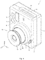
- FIG. 1 is a perspective view of a camera 1 according to one embodiment of the present invention.
- the camera 1 according to the present embodiment is a camera (instant camera) that uses a photographic film to be automatically developed after shooting
- the present invention is also applicable to a camera other than such an instant camera.
- the term front or frontward refers to the positive X-direction in FIG. 1
- the term rear or rearward refers to the negative X-direction in FIG. 1 .
- the camera 1 includes a front cover 2, a rear cover 3 attached to the rear of the front cover 2, a top cover 4 sandwiched between the front cover 2 and the rear cover 3, and a lens barrel 10 accommodated in a cylindrical portion 2A of the front cover 2.
- the front cover 2 has a viewfinder 5.
- a flash window 6 is located adjacent to the viewfinder 5.
- a release button 7 is located in the negative Z-direction from the viewfinder 5.
- the top cover 4 has an ejection slit 4A extending in Y-direction, from which a photographic film developed after shooting is ejected.
- FIG. 2 is an exploded perspective view of some of the components accommodated in an internal space defined by the front cover 2, the rear cover 3, and the top cover 4.
- the camera 1 includes a frame 20 including a film compartment 21 and a cylindrical barrel 22.
- the film compartment 21 has an accommodating space S in which a photographic film is placed.
- the barrel 22 is attached to the front (positive X-direction) of the film compartment 21.
- the barrel 22 has threaded holes 22A.
- the film compartment 21 also has threaded holes 21A.
- the barrel 22 is attached to the film compartment 21 with screws (not shown) screwed into the threaded holes 22A and 21A to form the frame 20.
- the barrel 22 attached to the film compartment 21 extends frontward (positive X-direction) from the film compartment 21 and holds the lens barrel 10 inside.
- FIG. 3 is a perspective view of the lens barrel 10 extending to its maximum length in the positive X-direction.
- the lens barrel 10 includes a first cylinder 11, a second cylinder 12, and a third cylinder 13.
- the first cylinder 11 is movable in X-direction relative to the barrel 22 in the frame 20.
- the second cylinder 12 is movable in X-direction relative to the first cylinder 11.
- the third cylinder 13 is movable in X-direction relative to the second cylinder 12.
- the first cylinder 11 and the second cylinder 12 are included in one lens barrel unit (rear lens barrel unit), and the third cylinder 13 is included in another lens barrel unit (front lens barrel unit).
- the lens barrel 10 includes, on the rear edge of the first cylinder 11, two engagement protrusions 14 protruding radially outward.
- the barrel 22 in the frame 20 has two guide grooves 24 corresponding to the engagement protrusions 14 and extending in the direction of an optical axis P (X-direction).
- Each engagement protrusion 14 on the lens barrel 10 is received in and engaged with the guide groove 24 on the barrel 22.
- the guide grooves 24 each have a width in Z-direction slightly larger than the width of the engagement protrusion 14 in Z-direction.
- the engagement protrusions 14 are thus movable in the direction of the optical axis P (X-direction) in the guide grooves 24 while being guided by the guide grooves 24.
- the barrel 22 in the frame 20 includes an operation button 8 urged in the positive X-direction.
- the operation button 8 protrudes from the front cover 2 in the positive X-direction near the cylindrical portion 2A of the front cover 2.
- a user can depress the operation button 8 in the negative X-direction.
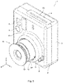
- the engagement protrusion 14 on the lens barrel 10 is pushed by a lens barrel extension assembly 9 attached to the barrel 22 in the positive X-direction, causing the lens barrel 10 to extend in the positive X-direction as shown in FIG. 4 .
- a switch assembly (not shown) turns on the camera 1.
- the structure of the lens barrel extension assembly 9 is not limited to a specific structure.
- the lens barrel extension assembly 9 may have any structure that can extend the lens barrel 10 in the positive X-direction.
- the second cylinder 12 is moved by a moving assembly (not shown) in the positive X-direction relative to the first cylinder 11 as the first cylinder 11 moves in the positive X-direction relative to the barrel 22.
- the second cylinder 12 extends from the first cylinder 11 in the positive X-direction.
- This state is hereafter referred to as a first photographing state.
- the user can manually pull the third cylinder 13 from the second cylinder 12 further in the positive X-direction in the state shown in FIG. 4 .
- the user can perform, for example, a short-distance macro photographing operation. This state is hereafter referred to as a second photographing state.
- FIG. 1 shows the lens barrel 10 accommodated in the barrel 22 in the frame 20.
- the lens barrel 10 has a minimum length in X-direction in this state. This state is hereafter referred to as a retracted state.
- FIG. 6 is a partial longitudinal cross-sectional view of the camera 1 in the retracted state.
- the third cylinder 13 accommodates a barrier 131, a first lens 132, an aperture 133, and a second lens 134 in this order from a subject (in the positive X-direction).
- a photographic film F is placed at a predetermined position in the accommodating space S in the film compartment 21.
- a rear bellows 50 is located between the first cylinder 11 in the lens barrel 10 and the film compartment 21 in the frame 20.
- the rear bellows 50 is formed from a flexible material such as rubber and expands and contracts as the first cylinder 11 moves relative to the barrel 22.
- the rear bellows 50 has a rectangular opening T inside. The opening T gradually enlarges from the first cylinder 11 toward the frame 20.
- the rear bellows 50 includes, on its rear end, a rectangular rear connector 51 flaring outward. The rear connector 51 is held between the film compartment 21 and the barrel 22 as shown in FIG. 6 .
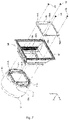
- FIG. 7 is an exploded perspective view describing attachment of the rear bellows 50.
- the rear bellows 50 includes, on its front end, a rectangular front connector 52 extending inward.
- the front connector 52 has multiple threaded holes 52A.
- the first cylinder 11 in the lens barrel 10 includes a rectangular frame-shaped connecting flange 41 (first connecting flange) in its rear end.
- the connecting flange 41 has threaded holes 41A corresponding to the threaded holes 52A in the front connector 52 in the rear bellows 50.
- a rectangular frame-shaped attachment plate 55 is located behind the front connector 52 in the rear bellows 50 (in the negative X-direction).
- the attachment plate 55 also has threaded holes 55A corresponding to the threaded holes 52A in the front connector 52 in the rear bellows 50. Screws 56 are screwed into the threaded holes 55A in the attachment plate 55, the threaded holes 52A in the front connector 52 in the rear bellows 50, and the threaded holes 41A in the connecting flange 41 in the first cylinder 11 to hold the front connector 52 in the rear bellows 50 between the attachment plate 55 and the connecting flange 41 in the first cylinder 11.
- a front bellows 60 is located between the first cylinder 11 and the third cylinder 13 in the lens barrel 10.
- the front bellows 60 is formed from a flexible material such as rubber and expands and contracts as the third cylinder 13 moves relative to the first cylinder 11.
- FIG. 8 is an exploded perspective view describing attachment of the front bellows 60.
- the front bellows 60 has a rectangular opening U inside.
- the opening U gradually enlarges from the third cylinder 13 toward the first cylinder 11.
- the front bellows 60 includes, on its rear end, a rectangular rear connector 61 flaring outward.
- a rectangular frame-shaped attachment plate 65 is located in front of the rear connector 61 in the front bellows 60 (in the positive X-direction).
- the attachment plate 65 has multiple threaded holes 65A.
- the connecting flange 41 in the first cylinder 11 described above has threaded holes 42A corresponding to the threaded holes 65A in the attachment plate 65.
- Screws 66 are screwed into the threaded holes 65A in the attachment plate 65 and the threaded holes 42A in the connecting flange 41 in the first cylinder 11 from one end of the connecting flange 41 facing the third cylinder 13 to hold the rear connector 61 in the front bellows 60 between the attachment plate 65 and the connecting flange 41 in the first cylinder 11.
- the front bellows 60 includes, on its front end, a rectangular front connector 62 extending inward.
- the front connector 62 has multiple threaded holes 62A.
- the third cylinder 13 in the lens barrel 10 includes a rectangular frame-shaped connecting flange 31 (second connecting flange) on its rear end.
- the connecting flange 31 has threaded holes 31A corresponding to the threaded holes 62A in the front connector 62 in the front bellows 60.
- the connecting flange 31 may be integral with the third cylinder 13 or may be a separate component from the third cylinder 13.
- a rectangular frame-shaped attachment plate 67 is located behind the front connector 62 in the front bellows 60 (in the negative X-direction).
- the attachment plate 67 also has threaded holes 67A corresponding to the threaded holes 62A in the front connector 62 in the front bellows 60.
- Screws 68 are screwed into the threaded holes 67A in the attachment plate 67, the threaded holes 62A in the front connector 62 in the front bellows 60, and the threaded holes 31A in the connecting flange 31 on the third cylinder 13 to hold the front connector 62 in the front bellows 60 between the attachment plate 67 and the connecting flange 31 on the third cylinder 13.
- the first cylinder 11 and the second cylinder 12 in the lens barrel 10 are accommodated radially inside the barrel 22, and the third cylinder 13 is accommodated radially inside the second cylinder 12.
- the first cylinder 11 is at its farthest extent in the negative X-direction.
- the rear bellows 50 is contracted in X-direction.
- the third cylinder 13 is nearest the first cylinder 11 in X-direction.
- the front bellows 60 is contracted in X-direction.
- the camera 1 is not turned on, and photographing with the camera 1 is not performed.
- FIG. 9 is a partial longitudinal cross-sectional view of the camera 1 in the first photographing state shown in FIG. 4 .
- the first cylinder 11 in the lens barrel 10 extends in the positive X-direction relative to the barrel 22, and the second cylinder 12 is extended by the moving assembly (not shown) in the positive X-direction relative to the first cylinder 11, causing the camera 1 to be in the first photographing state shown in FIG. 9 .
- the third cylinder 13 in the lens barrel 10 is accommodated radially inside the second cylinder 12.
- the first cylinder 11 in the lens barrel 10 extends in the positive X-direction relative to the barrel 22, and the rear bellows 50 is thus expanded.
- the rear bellows 50 is outside a light beam B1 projected from the second lens 134 onto the photographic film F and thus avoids being captured in an image projected onto the photographic film F.
- the second cylinder 12 in the lens barrel 10 extends in the positive X-direction relative to the first cylinder 11 in the first photographing state.
- the front bellows 60 is thus expanded slightly further than in the retracted state shown in FIG. 6 .
- the front bellows 60 is outside the light beam B1 projected from the second lens 134 onto the photographic film F and thus avoids being captured in an image projected onto the photographic film F.
- both the rear bellows 50 and the front bellows 60 are outside the light beam B1 projected from the second lens 134 onto the photographic film F and avoid being captured in an image projected onto the photographic film F.
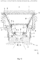
- FIG. 10 is a partial longitudinal cross-sectional view of the camera 1 in the second photographing state shown in FIG. 5 .
- the camera 1 enters the second photographing state shown in FIG. 10 .
- the third cylinder 13 in the lens barrel 10 in the first photographing state described above extends in the positive X-direction relative to the second cylinder 12.
- the front bellows 60 is thus expanded further than in the first photographing state shown in FIG. 9 .
- the front bellows 60 is outside a light beam B2 projected from the second lens 134 onto the photographic film F and thus avoids being captured in an image projected onto the photographic film F. In this manner, in the second photographing state as well, both the rear bellows 50 and the front bellows 60 are outside the light beam B2 projected from the second lens 134 onto the photographic film F and avoid being captured in an image projected onto the photographic film F.
- the rear bellows 50 connecting the frame 20 and the first cylinder 11 in the lens barrel 10 and the front bellows 60 connecting the first cylinder 11 and the third cylinder 13 in the lens barrel 10 are included.
- the rear bellows 50 and the front bellows 60 are outside the light beams B1 and B2 projected from the second lens 134 onto the photographic film F and avoid being captured in an image projected onto the photographic film F.
- photographing without vignetting can be performed with the rear bellows 50 and the front bellows 60 preventing entry of light and dust. This allows two different photographing (e.g., normal photographing and macro photographing) operations with the lenses 132 and 134 at different positions.
- the rear bellows 50 and the front bellows 60 are both connected to the single connecting flange 41 in the rear end of the first cylinder 11 in the lens barrel 10.
- This structure includes fewer components to reduce cost and also downsizes the camera 1.
- the rear lens barrel unit includes the first cylinder 11 and the second cylinder 12 in the lens barrel 10 in the above embodiment
- the rear lens barrel unit may include a single cylinder or three or more cylinders.
- the second cylinder 12 is accommodated radially inside the first cylinder 11 in the retracted state.
- the camera 1 can thus be thinner in the optical axis direction.
- the front lens barrel unit includes the third cylinder 13 in the lens barrel 10 in the above embodiment, the front lens barrel unit may include two or more cylinders.
- a camera can perform two different photographing operations with a lens at different positions without vignetting while preventing entry of light and dust.
- the camera includes a frame including a film compartment to contain a photographic film and a barrel extending from the film compartment in an optical axis direction, and a lens barrel movable in the barrel in the optical axis direction.
- the lens barrel includes a rear lens barrel unit accommodated radially inside the barrel and movable frontward relative to the barrel, and a front lens barrel unit accommodated radially inside the rear lens barrel unit and movable frontward relative to the rear lens barrel unit.
- the front lens barrel unit accommodates at least one lens.
- the camera further includes a rear bellows connecting the frame and the rear lens barrel unit, and a front bellows connecting the rear lens barrel unit and the front lens barrel unit.
- the lens barrel has a retracted state in which the rear lens barrel unit is accommodated radially inside the barrel, and the front lens barrel unit is accommodated radially inside the rear lens barrel unit, a first photographing state in which the rear lens barrel unit extends frontward relative to the barrel, and the front lens barrel unit is accommodated radially inside the rear lens barrel unit, and a second photographing state in which the rear lens barrel unit extends frontward relative to the barrel, and the front lens barrel unit extends frontward relative to the rear lens barrel unit.
- the rear bellows In the first photographing state, the rear bellows is expanded and is outside a light beam projected from the at least one lens onto the photographic film, and the front bellows is at least partially contracted and is outside the light beam projected from the at least one lens onto the photographic film. In the retracted state, both the front bellows and the rear bellows may be at least partially contracted.
- This structure includes the rear bellows connecting the frame and the rear lens barrel unit and the front bellows connecting the rear lens barrel unit and the front lens barrel unit.
- the rear bellows and the front bellows are outside the light beams projected from the lens onto the photographic film and avoid being captured in an image projected onto the photographic film.
- photographing without vignetting can be performed with the rear bellows and the front bellows preventing entry of light and dust. This allows two different photographing (e.g., normal photographing and macro photographing) operations with the lens at different positions without vignetting.
- the rear lens barrel unit may include a first cylinder and a second cylinder accommodated radially inside the first cylinder and movable frontward relative to the first cylinder.
- the front lens barrel unit may include a second cylinder that is accommodated radially inside the second cylinder in the rear lens barrel unit in the first photographing state and extends frontward relative to the second cylinder in the rear lens barrel unit in the second photographing state.
- the camera with this structure can be thinner in the optical axis direction in the retracted state.
- the rear lens barrel unit may include a first connecting flange to which the rear bellows and the front bellows are connected. This structure in which the rear bellows and the front bellows are connected to the single connecting flange includes fewer components to reduce cost and also downsizes the camera.
- the front lens barrel unit may include a second connecting flange to which the front bellows is connected.
- the camera according to the above aspects of the present invention includes the rear bellows connecting the frame and the rear lens barrel unit and the front bellows connecting the rear lens barrel unit and the front lens barrel unit.
- the rear bellows and the front bellows are outside the light beams projected from the lens onto the photographic film and avoid being captured in an image projected onto the photographic film.
- photographing without vignetting can be performed with the rear bellows and the front bellows preventing entry of light and dust. This allows two different photographing (e.g., normal photographing and macro photographing) operations with the lens at different positions without vignetting.
- the camera according to one or more embodiments of the present invention is suitably used as a camera that allows a lens barrel to extend with a flexible bellows.
Landscapes
- Physics & Mathematics (AREA)
- General Physics & Mathematics (AREA)
- Optics & Photonics (AREA)
- Structure And Mechanism Of Cameras (AREA)
- Lens Barrels (AREA)
- Camera Bodies And Camera Details Or Accessories (AREA)
Abstract
Description
- The present invention relates to a camera, and particularly, to a camera that allows a lens barrel to extend with a flexible bellows.
- A known camera includes a lens barrel extension assembly for allowing a lens barrel to extend frontward in an optical axis direction. In such a camera, the lens barrel is typically connected to the camera body with a flexible bellows for preventing entry of light and dust (refer to, for example, Patent Literature 1). To perform a short-distance photographing (macro photographing) operation in addition to a normal photographing operation, the lens barrel is to be extended further than for the normal photographing operation. The bellows described above expands and contracts to a greater extent for the lens barrel extendable by a greater distance. The bellows can thus be captured in an image projected onto a photographic film when contracted, thus causing vignetting.
- Patent Literature 1:
Japanese Unexamined Patent Application Publication No. 2004-233381 - In response to the above issue, one or more aspects of the present invention are directed to a camera that can perform two different photographing operations with a lens at different positions without vignetting while preventing entry of light and dust.
- A camera according to one aspect of the present invention can perform two different photographing operations with a lens at different positions without vignetting while preventing entry of light and dust. The camera includes a frame including a film compartment to contain a photographic film and a barrel extending from the film compartment in an optical axis direction, and a lens barrel movable in the barrel in the optical axis direction. The lens barrel includes a rear lens barrel unit accommodated radially inside the barrel and movable frontward relative to the barrel, and a front lens barrel unit accommodated radially inside the rear lens barrel unit and movable frontward relative to the rear lens barrel unit. The front lens barrel unit accommodates at least one lens. The camera further includes a rear bellows connecting the frame and the rear lens barrel unit, and a front bellows connecting the rear lens barrel unit and the front lens barrel unit. The lens barrel has a retracted state in which the rear lens barrel unit is accommodated radially inside the barrel, and the front lens barrel unit is accommodated radially inside the rear lens barrel unit, a first photographing state in which the rear lens barrel unit extends frontward relative to the barrel, and the front lens barrel unit is accommodated radially inside the rear lens barrel unit, and a second photographing state in which the rear lens barrel unit extends frontward relative to the barrel, and the front lens barrel unit extends frontward relative to the rear lens barrel unit. In the first photographing state, the rear bellows is expanded and is outside a light beam projected from the at least one lens onto the photographic film, and the front bellows is at least partially contracted and is outside the light beam projected from the at least one lens onto the photographic film.
-
-
FIG. 1 is a perspective view of a camera according to one embodiment of the present invention. -
FIG. 2 is an exploded perspective view of some of the components of the camera shown inFIG. 1 accommodated in an internal space defined by a front cover, a rear cover, and a top cover. -
FIG. 3 is a perspective view of a lens barrel shown inFIG. 2 extending to its maximum length in the positive X-direction. -
FIG. 4 is a perspective view of the camera shown inFIG. 1 in a first photographing state. -
FIG. 5 is a perspective view of the camera shown inFIG. 1 in a second photographing state. -
FIG. 6 is a partial longitudinal cross-sectional view of the camera shown inFIG. 1 in a retracted state. -
FIG. 7 is an exploded perspective view describing attachment of a rear bellows shown inFIG. 2 . -
FIG. 8 is an exploded perspective view describing attachment of a front bellows shown inFIG. 6 . -
FIG. 9 is a partial longitudinal cross-sectional view of the camera in the first photographing state shown inFIG. 4 . -
FIG. 10 is a partial longitudinal cross-sectional view of the camera in the second photographing state shown inFIG. 5 . - A camera according to one or more embodiments of the present invention will now be described in detail with reference to
FIGs. 1 to 10 . InFIGs. 1 to 10 , like reference numerals denote like or corresponding components. Such components will not be described repeatedly. InFIGs. 1 to 10 , the scale and dimensions of each component may be exaggerated, or one or more components may not be shown. -
FIG. 1 is a perspective view of a camera 1 according to one embodiment of the present invention. Although the camera 1 according to the present embodiment is a camera (instant camera) that uses a photographic film to be automatically developed after shooting, the present invention is also applicable to a camera other than such an instant camera. For ease of explanation in the present embodiment, the term front or frontward refers to the positive X-direction inFIG. 1 , and the term rear or rearward refers to the negative X-direction inFIG. 1 . - As shown in
FIG. 1 , the camera 1 includes afront cover 2, arear cover 3 attached to the rear of thefront cover 2, a top cover 4 sandwiched between thefront cover 2 and therear cover 3, and alens barrel 10 accommodated in acylindrical portion 2A of thefront cover 2. Thefront cover 2 has aviewfinder 5. Aflash window 6 is located adjacent to theviewfinder 5. Arelease button 7 is located in the negative Z-direction from theviewfinder 5. The top cover 4 has anejection slit 4A extending in Y-direction, from which a photographic film developed after shooting is ejected. -
FIG. 2 is an exploded perspective view of some of the components accommodated in an internal space defined by thefront cover 2, therear cover 3, and the top cover 4. As shown inFIG. 2 , the camera 1 includes aframe 20 including afilm compartment 21 and acylindrical barrel 22. Thefilm compartment 21 has an accommodating space S in which a photographic film is placed. Thebarrel 22 is attached to the front (positive X-direction) of thefilm compartment 21. Thebarrel 22 has threadedholes 22A. Thefilm compartment 21 also has threadedholes 21A. Thebarrel 22 is attached to thefilm compartment 21 with screws (not shown) screwed into the threadedholes frame 20. Thebarrel 22 attached to thefilm compartment 21 extends frontward (positive X-direction) from thefilm compartment 21 and holds thelens barrel 10 inside. - The
lens barrel 10 in the present embodiment is extendable in the positive X-direction.FIG. 3 is a perspective view of thelens barrel 10 extending to its maximum length in the positive X-direction. As shown inFIG. 3 , thelens barrel 10 includes afirst cylinder 11, asecond cylinder 12, and athird cylinder 13. Thefirst cylinder 11 is movable in X-direction relative to thebarrel 22 in theframe 20. Thesecond cylinder 12 is movable in X-direction relative to thefirst cylinder 11. Thethird cylinder 13 is movable in X-direction relative to thesecond cylinder 12. In the present embodiment, thefirst cylinder 11 and thesecond cylinder 12 are included in one lens barrel unit (rear lens barrel unit), and thethird cylinder 13 is included in another lens barrel unit (front lens barrel unit). - As shown in
FIG. 3 , thelens barrel 10 includes, on the rear edge of thefirst cylinder 11, twoengagement protrusions 14 protruding radially outward. As shown inFIG. 2 , thebarrel 22 in theframe 20 has twoguide grooves 24 corresponding to theengagement protrusions 14 and extending in the direction of an optical axis P (X-direction). Eachengagement protrusion 14 on thelens barrel 10 is received in and engaged with theguide groove 24 on thebarrel 22. Theguide grooves 24 each have a width in Z-direction slightly larger than the width of theengagement protrusion 14 in Z-direction. Theengagement protrusions 14 are thus movable in the direction of the optical axis P (X-direction) in theguide grooves 24 while being guided by theguide grooves 24. - As shown in
FIG. 2 , thebarrel 22 in theframe 20 includes anoperation button 8 urged in the positive X-direction. As shown inFIG. 1 , theoperation button 8 protrudes from thefront cover 2 in the positive X-direction near thecylindrical portion 2A of thefront cover 2. A user can depress theoperation button 8 in the negative X-direction. When the user depresses theoperation button 8 in the negative X-direction, theengagement protrusion 14 on thelens barrel 10 is pushed by a lens barrel extension assembly 9 attached to thebarrel 22 in the positive X-direction, causing thelens barrel 10 to extend in the positive X-direction as shown inFIG. 4 . In response to thelens barrel 10 protruding from thebarrel 22 in the positive X-direction, a switch assembly (not shown) turns on the camera 1. The structure of the lens barrel extension assembly 9 is not limited to a specific structure. The lens barrel extension assembly 9 may have any structure that can extend thelens barrel 10 in the positive X-direction. - In the present embodiment, the
second cylinder 12 is moved by a moving assembly (not shown) in the positive X-direction relative to thefirst cylinder 11 as thefirst cylinder 11 moves in the positive X-direction relative to thebarrel 22. Thus, as shown inFIG. 4 , thesecond cylinder 12 extends from thefirst cylinder 11 in the positive X-direction. In this state, the user can perform a normal photographing operation. This state is hereafter referred to as a first photographing state. - In the present embodiment, the user can manually pull the
third cylinder 13 from thesecond cylinder 12 further in the positive X-direction in the state shown inFIG. 4 . Thethird cylinder 13, which is pulled from thesecond cylinder 12 further in the positive X-direction, extends from thesecond cylinder 12 in the positive X-direction as shown inFIG. 5 . In this state, the user can perform, for example, a short-distance macro photographing operation. This state is hereafter referred to as a second photographing state. -
FIG. 1 shows thelens barrel 10 accommodated in thebarrel 22 in theframe 20. Thelens barrel 10 has a minimum length in X-direction in this state. This state is hereafter referred to as a retracted state.FIG. 6 is a partial longitudinal cross-sectional view of the camera 1 in the retracted state. As shown inFIG. 6 , thethird cylinder 13 accommodates abarrier 131, afirst lens 132, anaperture 133, and asecond lens 134 in this order from a subject (in the positive X-direction). A photographic film F is placed at a predetermined position in the accommodating space S in thefilm compartment 21. - As shown in
FIG. 6 , a rear bellows 50 is located between thefirst cylinder 11 in thelens barrel 10 and thefilm compartment 21 in theframe 20. The rear bellows 50 is formed from a flexible material such as rubber and expands and contracts as thefirst cylinder 11 moves relative to thebarrel 22. As shown inFIG. 2 , the rear bellows 50 has a rectangular opening T inside. The opening T gradually enlarges from thefirst cylinder 11 toward theframe 20. The rear bellows 50 includes, on its rear end, a rectangularrear connector 51 flaring outward. Therear connector 51 is held between thefilm compartment 21 and thebarrel 22 as shown inFIG. 6 . -
FIG. 7 is an exploded perspective view describing attachment of the rear bellows 50. As shown inFIGs. 2 and7 , the rear bellows 50 includes, on its front end, a rectangularfront connector 52 extending inward. Thefront connector 52 has multiple threadedholes 52A. As shown inFIG. 7 , thefirst cylinder 11 in thelens barrel 10 includes a rectangular frame-shaped connecting flange 41 (first connecting flange) in its rear end. The connectingflange 41 has threadedholes 41A corresponding to the threadedholes 52A in thefront connector 52 in the rear bellows 50. A rectangular frame-shapedattachment plate 55 is located behind thefront connector 52 in the rear bellows 50 (in the negative X-direction). Theattachment plate 55 also has threadedholes 55A corresponding to the threadedholes 52A in thefront connector 52 in the rear bellows 50.Screws 56 are screwed into the threadedholes 55A in theattachment plate 55, the threadedholes 52A in thefront connector 52 in the rear bellows 50, and the threadedholes 41A in the connectingflange 41 in thefirst cylinder 11 to hold thefront connector 52 in the rear bellows 50 between theattachment plate 55 and the connectingflange 41 in thefirst cylinder 11. - As shown in
FIG. 6 , a front bellows 60 is located between thefirst cylinder 11 and thethird cylinder 13 in thelens barrel 10. The front bellows 60 is formed from a flexible material such as rubber and expands and contracts as thethird cylinder 13 moves relative to thefirst cylinder 11. -
FIG. 8 is an exploded perspective view describing attachment of the front bellows 60. As shown inFIG. 8 , the front bellows 60 has a rectangular opening U inside. The opening U gradually enlarges from thethird cylinder 13 toward thefirst cylinder 11. As shown inFIG. 8 , the front bellows 60 includes, on its rear end, a rectangularrear connector 61 flaring outward. A rectangular frame-shapedattachment plate 65 is located in front of therear connector 61 in the front bellows 60 (in the positive X-direction). Theattachment plate 65 has multiple threadedholes 65A. The connectingflange 41 in thefirst cylinder 11 described above has threadedholes 42A corresponding to the threadedholes 65A in theattachment plate 65.Screws 66 are screwed into the threadedholes 65A in theattachment plate 65 and the threadedholes 42A in the connectingflange 41 in thefirst cylinder 11 from one end of the connectingflange 41 facing thethird cylinder 13 to hold therear connector 61 in the front bellows 60 between theattachment plate 65 and the connectingflange 41 in thefirst cylinder 11. - As shown in
FIG. 8 , the front bellows 60 includes, on its front end, a rectangularfront connector 62 extending inward. Thefront connector 62 has multiple threadedholes 62A. Thethird cylinder 13 in thelens barrel 10 includes a rectangular frame-shaped connecting flange 31 (second connecting flange) on its rear end. The connectingflange 31 has threadedholes 31A corresponding to the threadedholes 62A in thefront connector 62 in the front bellows 60. The connectingflange 31 may be integral with thethird cylinder 13 or may be a separate component from thethird cylinder 13. - A rectangular frame-shaped
attachment plate 67 is located behind thefront connector 62 in the front bellows 60 (in the negative X-direction). Theattachment plate 67 also has threadedholes 67A corresponding to the threadedholes 62A in thefront connector 62 in the front bellows 60.Screws 68 are screwed into the threadedholes 67A in theattachment plate 67, the threadedholes 62A in thefront connector 62 in the front bellows 60, and the threadedholes 31A in the connectingflange 31 on thethird cylinder 13 to hold thefront connector 62 in the front bellows 60 between theattachment plate 67 and the connectingflange 31 on thethird cylinder 13. - In the retracted state shown in
FIG. 6 , thefirst cylinder 11 and thesecond cylinder 12 in thelens barrel 10 are accommodated radially inside thebarrel 22, and thethird cylinder 13 is accommodated radially inside thesecond cylinder 12. Thefirst cylinder 11 is at its farthest extent in the negative X-direction. The rear bellows 50 is contracted in X-direction. Thethird cylinder 13 is nearest thefirst cylinder 11 in X-direction. The front bellows 60 is contracted in X-direction. In this state, the camera 1 is not turned on, and photographing with the camera 1 is not performed. -
FIG. 9 is a partial longitudinal cross-sectional view of the camera 1 in the first photographing state shown inFIG. 4 . As described above, when the user depresses theoperation button 8 in the retracted state shown inFIG. 6 , thefirst cylinder 11 in thelens barrel 10 extends in the positive X-direction relative to thebarrel 22, and thesecond cylinder 12 is extended by the moving assembly (not shown) in the positive X-direction relative to thefirst cylinder 11, causing the camera 1 to be in the first photographing state shown inFIG. 9 . In the first photographing state, thethird cylinder 13 in thelens barrel 10 is accommodated radially inside thesecond cylinder 12. - In the first photographing state, the
first cylinder 11 in thelens barrel 10 extends in the positive X-direction relative to thebarrel 22, and the rear bellows 50 is thus expanded. The rear bellows 50 is outside a light beam B1 projected from thesecond lens 134 onto the photographic film F and thus avoids being captured in an image projected onto the photographic film F. In the present embodiment, thesecond cylinder 12 in thelens barrel 10 extends in the positive X-direction relative to thefirst cylinder 11 in the first photographing state. The front bellows 60 is thus expanded slightly further than in the retracted state shown inFIG. 6 . The front bellows 60 is outside the light beam B1 projected from thesecond lens 134 onto the photographic film F and thus avoids being captured in an image projected onto the photographic film F. In this manner, in the first photographing state, both the rear bellows 50 and the front bellows 60 are outside the light beam B1 projected from thesecond lens 134 onto the photographic film F and avoid being captured in an image projected onto the photographic film F. -
FIG. 10 is a partial longitudinal cross-sectional view of the camera 1 in the second photographing state shown inFIG. 5 . When the user manually pulls thethird cylinder 13 from thesecond cylinder 12 in the positive X-direction in the first photographing state shown inFIG. 9 , the camera 1 enters the second photographing state shown inFIG. 10 . In the second photographing state, thethird cylinder 13 in thelens barrel 10 in the first photographing state described above extends in the positive X-direction relative to thesecond cylinder 12. The front bellows 60 is thus expanded further than in the first photographing state shown inFIG. 9 . The front bellows 60 is outside a light beam B2 projected from thesecond lens 134 onto the photographic film F and thus avoids being captured in an image projected onto the photographic film F. In this manner, in the second photographing state as well, both the rear bellows 50 and the front bellows 60 are outside the light beam B2 projected from thesecond lens 134 onto the photographic film F and avoid being captured in an image projected onto the photographic film F. - As described above, in the present embodiment, the rear bellows 50 connecting the
frame 20 and thefirst cylinder 11 in thelens barrel 10 and the front bellows 60 connecting thefirst cylinder 11 and thethird cylinder 13 in thelens barrel 10 are included. Thus, both in the first photographing state shown inFIG. 9 and in the second photographing state shown inFIG. 10 , the rear bellows 50 and the front bellows 60 are outside the light beams B1 and B2 projected from thesecond lens 134 onto the photographic film F and avoid being captured in an image projected onto the photographic film F. Thus, when the positions of thelenses lenses - In the above embodiment, the rear bellows 50 and the front bellows 60 are both connected to the single connecting
flange 41 in the rear end of thefirst cylinder 11 in thelens barrel 10. This structure includes fewer components to reduce cost and also downsizes the camera 1. - Although the rear lens barrel unit includes the
first cylinder 11 and thesecond cylinder 12 in thelens barrel 10 in the above embodiment, the rear lens barrel unit may include a single cylinder or three or more cylinders. In the structure including the rear lens barrel unit that includes thefirst cylinder 11 and thesecond cylinder 12 in thelens barrel 10 as in the present embodiment, thesecond cylinder 12 is accommodated radially inside thefirst cylinder 11 in the retracted state. The camera 1 can thus be thinner in the optical axis direction. Although the front lens barrel unit includes thethird cylinder 13 in thelens barrel 10 in the above embodiment, the front lens barrel unit may include two or more cylinders. - The terms front, frontward, rear, rearward, up, upward, down, downward, and other terms used herein to indicate the positional relationships are used in connection with the illustrated embodiment and are thus changeable depending on the relative positional relationship in the device.
- Although the embodiments of the present invention have been described above, the present invention is not limited to the above embodiments and may be modified variously within the scope of its technical idea.
- As described above, a camera according to the above aspects of the present invention can perform two different photographing operations with a lens at different positions without vignetting while preventing entry of light and dust. The camera includes a frame including a film compartment to contain a photographic film and a barrel extending from the film compartment in an optical axis direction, and a lens barrel movable in the barrel in the optical axis direction. The lens barrel includes a rear lens barrel unit accommodated radially inside the barrel and movable frontward relative to the barrel, and a front lens barrel unit accommodated radially inside the rear lens barrel unit and movable frontward relative to the rear lens barrel unit. The front lens barrel unit accommodates at least one lens. The camera further includes a rear bellows connecting the frame and the rear lens barrel unit, and a front bellows connecting the rear lens barrel unit and the front lens barrel unit. The lens barrel has a retracted state in which the rear lens barrel unit is accommodated radially inside the barrel, and the front lens barrel unit is accommodated radially inside the rear lens barrel unit, a first photographing state in which the rear lens barrel unit extends frontward relative to the barrel, and the front lens barrel unit is accommodated radially inside the rear lens barrel unit, and a second photographing state in which the rear lens barrel unit extends frontward relative to the barrel, and the front lens barrel unit extends frontward relative to the rear lens barrel unit. In the first photographing state, the rear bellows is expanded and is outside a light beam projected from the at least one lens onto the photographic film, and the front bellows is at least partially contracted and is outside the light beam projected from the at least one lens onto the photographic film. In the retracted state, both the front bellows and the rear bellows may be at least partially contracted.
- This structure includes the rear bellows connecting the frame and the rear lens barrel unit and the front bellows connecting the rear lens barrel unit and the front lens barrel unit. Thus, both in the first photographing state and in the second photographing state, the rear bellows and the front bellows are outside the light beams projected from the lens onto the photographic film and avoid being captured in an image projected onto the photographic film. Thus, when the position of the lens is changed, photographing without vignetting can be performed with the rear bellows and the front bellows preventing entry of light and dust. This allows two different photographing (e.g., normal photographing and macro photographing) operations with the lens at different positions without vignetting.
- The rear lens barrel unit may include a first cylinder and a second cylinder accommodated radially inside the first cylinder and movable frontward relative to the first cylinder. In this case, the front lens barrel unit may include a second cylinder that is accommodated radially inside the second cylinder in the rear lens barrel unit in the first photographing state and extends frontward relative to the second cylinder in the rear lens barrel unit in the second photographing state.
- The camera with this structure can be thinner in the optical axis direction in the retracted state.
- The rear lens barrel unit may include a first connecting flange to which the rear bellows and the front bellows are connected. This structure in which the rear bellows and the front bellows are connected to the single connecting flange includes fewer components to reduce cost and also downsizes the camera. The front lens barrel unit may include a second connecting flange to which the front bellows is connected.
- The camera according to the above aspects of the present invention includes the rear bellows connecting the frame and the rear lens barrel unit and the front bellows connecting the rear lens barrel unit and the front lens barrel unit. Thus, both in the first photographing state and in the second photographing state, the rear bellows and the front bellows are outside the light beams projected from the lens onto the photographic film and avoid being captured in an image projected onto the photographic film. Thus, when the position of the lens is changed, photographing without vignetting can be performed with the rear bellows and the front bellows preventing entry of light and dust. This allows two different photographing (e.g., normal photographing and macro photographing) operations with the lens at different positions without vignetting.
- This application claims priority to
Japanese Patent Application No. 2019-228954 filed on December 19, 2019 - The camera according to one or more embodiments of the present invention is suitably used as a camera that allows a lens barrel to extend with a flexible bellows.
-
- 1
- camera
- 2
- front cover
- 3
- rear cover
- 4
- top cover
- 5
- viewfinder
- 6
- flash window
- 7
- release button
- 8
- operation button
- 9
- lens barrel extension assembly
- 10
- lens barrel
- 11
- first cylinder
- 12
- second cylinder
- 13
- third cylinder
- 14
- engagement protrusion
- 20
- frame
- 21
- film compartment
- 22
- barrel
- 24
- guide groove
- 31
- connecting flange (second connecting flange)
- 41
- connecting flange (first connecting flange)
- 50
- rear bellows
- 51
- rear connector
- 52
- front connector
- 55
- attachment plate
- 60
- front bellows
- 61
- rear connector
- 62
- front connector
- 65
- attachment plate
- 67
- attachment plate
- 131
- barrier
- 132
- first lens
- 133
- aperture
- 134
- second lens
- F
- photographic film
- P
- optical axis
Claims (6)
- A camera, comprising:a frame including a film compartment to contain a photographic film and a barrel extending from the film compartment in an optical axis direction;a lens barrel movable in the barrel in the optical axis direction, the lens barrel includinga rear lens barrel unit accommodated radially inside the barrel and movable frontward relative to the barrel, anda front lens barrel unit accommodated radially inside the rear lens barrel unit and movable frontward relative to the rear lens barrel unit, the front lens barrel unit accommodating at least one lens;a rear bellows connecting the frame and the rear lens barrel unit; anda front bellows connecting the rear lens barrel unit and the front lens barrel unit,wherein the lens barrel hasa retracted state in which the rear lens barrel unit is accommodated radially inside the barrel and the front lens barrel unit is accommodated radially inside the rear lens barrel unit,a first photographing state in which the rear lens barrel unit extends frontward relative to the barrel and the front lens barrel unit is accommodated radially inside the rear lens barrel unit, anda second photographing state in which the rear lens barrel unit extends frontward relative to the barrel and the front lens barrel unit extends frontward relative to the rear lens barrel unit, andin the first photographing state, the rear bellows is expanded and is outside a light beam projected from the at least one lens onto the photographic film, and the front bellows is at least partially contracted and is outside the light beam projected from the at least one lens onto the photographic film.
- The camera according to claim 1, wherein
in the retracted state, each of the front bellows and the rear bellows is at least partially contracted. - The camera according to claim 1 or claim 2, whereinthe rear lens barrel unit includesa first cylinder, anda second cylinder accommodated radially inside the first cylinder and movable frontward relative to the first cylinder.
- The camera according to claim 3, wherein
the front lens barrel unit includes a third cylinder accommodated radially inside the second cylinder in the rear lens barrel unit in the first photographing state and extendable frontward relative to the second cylinder in the rear lens barrel unit in the second photographing state. - The camera according to any one of claims 1 to 4, wherein
the rear lens barrel unit includes a first connecting flange to which the rear bellows and the front bellows are connected. - The camera according to any one of claims 1 to 5, wherein
the front lens barrel unit includes a second connecting flange to which the front bellows is connected.
Applications Claiming Priority (2)
| Application Number | Priority Date | Filing Date | Title |
|---|---|---|---|
| JP2019228954 | 2019-12-19 | ||
| PCT/JP2020/045801 WO2021125003A1 (en) | 2019-12-19 | 2020-12-09 | Camera device |
Publications (2)
| Publication Number | Publication Date |
|---|---|
| EP4080276A1 true EP4080276A1 (en) | 2022-10-26 |
| EP4080276A4 EP4080276A4 (en) | 2024-01-24 |
Family
ID=76476573
Family Applications (1)
| Application Number | Title | Priority Date | Filing Date |
|---|---|---|---|
| EP20903221.8A Pending EP4080276A4 (en) | 2019-12-19 | 2020-12-09 | CAMERA |
Country Status (5)
| Country | Link |
|---|---|
| US (1) | US11921405B2 (en) |
| EP (1) | EP4080276A4 (en) |
| JP (1) | JP7197731B2 (en) |
| CN (1) | CN114830005B (en) |
| WO (1) | WO2021125003A1 (en) |
Cited By (1)
| Publication number | Priority date | Publication date | Assignee | Title |
|---|---|---|---|---|
| EP4403996A1 (en) * | 2023-01-23 | 2024-07-24 | Nidec Precision Corporation | Camera |
Families Citing this family (2)
| Publication number | Priority date | Publication date | Assignee | Title |
|---|---|---|---|---|
| JP7682762B2 (en) * | 2021-10-20 | 2025-05-26 | ニデックプレシジョン株式会社 | Camera equipment |
| JP7682764B2 (en) * | 2021-10-21 | 2025-05-26 | ニデックプレシジョン株式会社 | Camera equipment |
Family Cites Families (17)
| Publication number | Priority date | Publication date | Assignee | Title |
|---|---|---|---|---|
| CH102555A (en) * | 1922-08-25 | 1923-12-01 | Grundlehner Ernst | Establishment of photographic equipment in order to be able to produce photographs of various sizes. |
| US1576340A (en) * | 1924-03-06 | 1926-03-09 | Provost Henri Emile Le | System of photographic apparatus with curved focus |
| DE2613161C2 (en) * | 1976-03-27 | 1983-12-22 | Novoflex Fotogerätebau Karl Müller, 8940 Memmingen | Bellows adjustment device for photographic cameras |
| JPH07181579A (en) * | 1993-12-22 | 1995-07-21 | Olympus Optical Co Ltd | Camera |
| JPH08304903A (en) * | 1995-05-10 | 1996-11-22 | Olympus Optical Co Ltd | Light shielding device for camera |
| JPH09152541A (en) * | 1995-11-29 | 1997-06-10 | Nikon Corp | Shielding member and lens barrel |
| JP4129283B2 (en) * | 1997-04-18 | 2008-08-06 | オリンパス株式会社 | Lens barrel |
| JP3957238B2 (en) * | 1997-04-18 | 2007-08-15 | オリンパス株式会社 | Lens barrel |
| JP2000131585A (en) * | 1998-10-23 | 2000-05-12 | Nikon Corp | Lens barrel |
| JP2002162677A (en) * | 2000-11-28 | 2002-06-07 | Olympus Optical Co Ltd | Zoom camera |
| JP2002196209A (en) | 2000-12-26 | 2002-07-12 | Olympus Optical Co Ltd | Lens barrel |
| JP2002350954A (en) | 2001-03-19 | 2002-12-04 | Fuji Photo Film Co Ltd | Camera |
| JP2002318416A (en) * | 2001-04-23 | 2002-10-31 | Olympus Optical Co Ltd | Spring camera |
| JP4497817B2 (en) * | 2003-01-28 | 2010-07-07 | キヤノン株式会社 | Lens barrel mechanism and camera |
| JP4253597B2 (en) * | 2004-01-27 | 2009-04-15 | オリンパス株式会社 | Lens barrel and camera |
| CN100373197C (en) * | 2005-10-27 | 2008-03-05 | 中国科学院上海光学精密机械研究所 | Spatial Filter Lens Adjustment Mount |
| KR102582944B1 (en) * | 2016-06-13 | 2023-09-26 | 엘지이노텍 주식회사 | Camera module and optical apparatus |
-
2020
- 2020-12-09 WO PCT/JP2020/045801 patent/WO2021125003A1/en not_active Ceased
- 2020-12-09 JP JP2021565509A patent/JP7197731B2/en active Active
- 2020-12-09 CN CN202080087594.8A patent/CN114830005B/en active Active
- 2020-12-09 EP EP20903221.8A patent/EP4080276A4/en active Pending
- 2020-12-09 US US17/786,535 patent/US11921405B2/en active Active
Cited By (1)
| Publication number | Priority date | Publication date | Assignee | Title |
|---|---|---|---|---|
| EP4403996A1 (en) * | 2023-01-23 | 2024-07-24 | Nidec Precision Corporation | Camera |
Also Published As
| Publication number | Publication date |
|---|---|
| WO2021125003A1 (en) | 2021-06-24 |
| JP7197731B2 (en) | 2022-12-27 |
| CN114830005A (en) | 2022-07-29 |
| JPWO2021125003A1 (en) | 2021-06-24 |
| US11921405B2 (en) | 2024-03-05 |
| EP4080276A4 (en) | 2024-01-24 |
| US20230037456A1 (en) | 2023-02-09 |
| CN114830005B (en) | 2023-08-18 |
Similar Documents
| Publication | Publication Date | Title |
|---|---|---|
| US11921405B2 (en) | Camera | |
| US7988372B2 (en) | Camera having detachable lens module | |
| JP6976803B2 (en) | Imaging device | |
| JP2007199312A (en) | Lens barrel | |
| JP2017134306A (en) | Imaging apparatus | |
| US20240248377A1 (en) | Camera | |
| US8422880B2 (en) | Filter adapter | |
| EP3705940A1 (en) | Lens apparatus to which intermediate adapter is mountable, optical apparatus, and imaging system | |
| JP5143644B2 (en) | Support structure for light shielding member of lens barrel | |
| JP2020067575A (en) | Lens barrel | |
| US11899340B2 (en) | Camera | |
| US20230130292A1 (en) | Camera | |
| JP2010008745A (en) | Cam follower accommodating structure for lens barrel | |
| JP4804554B2 (en) | Lens barrel | |
| JP7163121B2 (en) | Imaging device | |
| JP6064420B2 (en) | Lens barrel and optical equipment | |
| CN213903921U (en) | Camera device | |
| US7577347B2 (en) | Image taking apparatus | |
| JP2004252365A (en) | Lens barrel | |
| JP7237720B2 (en) | Imaging device | |
| JP2008176045A (en) | Camera system, lens structure, and camera body | |
| JP2019152781A (en) | Lens barrel | |
| JP2022152175A (en) | camera device | |
| US6321041B1 (en) | Camera with magnetic recording unit | |
| JP2021149054A (en) | Camera device |
Legal Events
| Date | Code | Title | Description |
|---|---|---|---|
| STAA | Information on the status of an ep patent application or granted ep patent |
Free format text: STATUS: THE INTERNATIONAL PUBLICATION HAS BEEN MADE |
|
| PUAI | Public reference made under article 153(3) epc to a published international application that has entered the european phase |
Free format text: ORIGINAL CODE: 0009012 |
|
| STAA | Information on the status of an ep patent application or granted ep patent |
Free format text: STATUS: REQUEST FOR EXAMINATION WAS MADE |
|
| 17P | Request for examination filed |
Effective date: 20220713 |
|
| AK | Designated contracting states |
Kind code of ref document: A1 Designated state(s): AL AT BE BG CH CY CZ DE DK EE ES FI FR GB GR HR HU IE IS IT LI LT LU LV MC MK MT NL NO PL PT RO RS SE SI SK SM TR |
|
| DAV | Request for validation of the european patent (deleted) | ||
| DAX | Request for extension of the european patent (deleted) | ||
| A4 | Supplementary search report drawn up and despatched |
Effective date: 20231222 |
|
| RIC1 | Information provided on ipc code assigned before grant |
Ipc: G03B 17/12 20210101ALI20231218BHEP Ipc: G02B 7/22 20210101ALI20231218BHEP Ipc: G02B 7/04 20210101ALI20231218BHEP Ipc: G02B 7/02 20210101ALI20231218BHEP Ipc: G03B 17/04 20210101ALI20231218BHEP Ipc: G03B 17/02 20210101AFI20231218BHEP |
|
| STAA | Information on the status of an ep patent application or granted ep patent |
Free format text: STATUS: EXAMINATION IS IN PROGRESS |
|
| 17Q | First examination report despatched |
Effective date: 20250717 |