EP4080141A1 - Flash tank economizer and air conditioning system - Google Patents
Flash tank economizer and air conditioning system Download PDFInfo
- Publication number
- EP4080141A1 EP4080141A1 EP22169100.9A EP22169100A EP4080141A1 EP 4080141 A1 EP4080141 A1 EP 4080141A1 EP 22169100 A EP22169100 A EP 22169100A EP 4080141 A1 EP4080141 A1 EP 4080141A1
- Authority
- EP
- European Patent Office
- Prior art keywords
- economizer
- suction port
- refrigerant
- cylindrical housing
- choke portion
- Prior art date
- Legal status (The legal status is an assumption and is not a legal conclusion. Google has not performed a legal analysis and makes no representation as to the accuracy of the status listed.)
- Pending
Links
Images
Classifications
-
- F—MECHANICAL ENGINEERING; LIGHTING; HEATING; WEAPONS; BLASTING
- F25—REFRIGERATION OR COOLING; COMBINED HEATING AND REFRIGERATION SYSTEMS; HEAT PUMP SYSTEMS; MANUFACTURE OR STORAGE OF ICE; LIQUEFACTION SOLIDIFICATION OF GASES
- F25B—REFRIGERATION MACHINES, PLANTS OR SYSTEMS; COMBINED HEATING AND REFRIGERATION SYSTEMS; HEAT PUMP SYSTEMS
- F25B43/00—Arrangements for separating or purifying gases or liquids; Arrangements for vaporising the residuum of liquid refrigerant, e.g. by heat
-
- F—MECHANICAL ENGINEERING; LIGHTING; HEATING; WEAPONS; BLASTING
- F25—REFRIGERATION OR COOLING; COMBINED HEATING AND REFRIGERATION SYSTEMS; HEAT PUMP SYSTEMS; MANUFACTURE OR STORAGE OF ICE; LIQUEFACTION SOLIDIFICATION OF GASES
- F25B—REFRIGERATION MACHINES, PLANTS OR SYSTEMS; COMBINED HEATING AND REFRIGERATION SYSTEMS; HEAT PUMP SYSTEMS
- F25B41/00—Fluid-circulation arrangements
-
- F—MECHANICAL ENGINEERING; LIGHTING; HEATING; WEAPONS; BLASTING
- F25—REFRIGERATION OR COOLING; COMBINED HEATING AND REFRIGERATION SYSTEMS; HEAT PUMP SYSTEMS; MANUFACTURE OR STORAGE OF ICE; LIQUEFACTION SOLIDIFICATION OF GASES
- F25B—REFRIGERATION MACHINES, PLANTS OR SYSTEMS; COMBINED HEATING AND REFRIGERATION SYSTEMS; HEAT PUMP SYSTEMS
- F25B1/00—Compression machines, plants or systems with non-reversible cycle
- F25B1/10—Compression machines, plants or systems with non-reversible cycle with multi-stage compression
-
- F—MECHANICAL ENGINEERING; LIGHTING; HEATING; WEAPONS; BLASTING
- F25—REFRIGERATION OR COOLING; COMBINED HEATING AND REFRIGERATION SYSTEMS; HEAT PUMP SYSTEMS; MANUFACTURE OR STORAGE OF ICE; LIQUEFACTION SOLIDIFICATION OF GASES
- F25B—REFRIGERATION MACHINES, PLANTS OR SYSTEMS; COMBINED HEATING AND REFRIGERATION SYSTEMS; HEAT PUMP SYSTEMS
- F25B40/00—Subcoolers, desuperheaters or superheaters
-
- F—MECHANICAL ENGINEERING; LIGHTING; HEATING; WEAPONS; BLASTING
- F25—REFRIGERATION OR COOLING; COMBINED HEATING AND REFRIGERATION SYSTEMS; HEAT PUMP SYSTEMS; MANUFACTURE OR STORAGE OF ICE; LIQUEFACTION SOLIDIFICATION OF GASES
- F25B—REFRIGERATION MACHINES, PLANTS OR SYSTEMS; COMBINED HEATING AND REFRIGERATION SYSTEMS; HEAT PUMP SYSTEMS
- F25B2400/00—Component parts or details not otherwise provided for in this subclass
- F25B2400/13—Economisers
-
- F—MECHANICAL ENGINEERING; LIGHTING; HEATING; WEAPONS; BLASTING
- F25—REFRIGERATION OR COOLING; COMBINED HEATING AND REFRIGERATION SYSTEMS; HEAT PUMP SYSTEMS; MANUFACTURE OR STORAGE OF ICE; LIQUEFACTION SOLIDIFICATION OF GASES
- F25B—REFRIGERATION MACHINES, PLANTS OR SYSTEMS; COMBINED HEATING AND REFRIGERATION SYSTEMS; HEAT PUMP SYSTEMS
- F25B2400/00—Component parts or details not otherwise provided for in this subclass
- F25B2400/23—Separators
Definitions
- the present invention relates to the field of air conditioning, in particular to an economizer and an air conditioning system having the same.
- refrigeration systems and associated equipment have been widely used in various temperature control fields including household air conditioning, commercial air conditioning, cold chain transportation, and cryogenic storage.
- large refrigeration equipment is usually used for application scenarios with low evaporating temperature and large cooling capacity demand, such as refrigeration and low-temperature environmental laboratories.
- An economizer is a commonly used component in large refrigeration systems. It is used to make a part of the refrigerant itself throttle and evaporate to absorb heat, so that the other part of the refrigerant is supercooled, that is, the liquid-phase refrigerant and the gas-phase refrigerant flowing through the economizer are made to be fully separated from each other.
- an economizer can be used in refrigeration systems with multistage compressor units.
- An economizer is a component for improving the energy efficiency of an air conditioning system. It has become a research direction for the modification of the economizer to further improve its reliability or efficiency from various aspects. Taking large refrigeration equipment as an example, the economizer thereof often faces the liquid carryover (LCO) problem when it is working. If the number of liquid droplets carried by the gas-phase refrigerant is small, it will not affect the compressor, and even help the compressor work, such as absorbing part of the vibration energy to help reduce vibration. However, excess liquid droplets may cause corrosion problems in components within the compressor, and may absorb too much compression energy and thus affects system efficiency, which are not desirable.
- LCO liquid carryover
- the present invention aims to provide an economizer and an air conditioning system, so as to at least partially solve or alleviate the problems existing in the prior art.
- an economizer which comprises: a housing with a refrigerant inlet for connecting to a first heat exchanger, a refrigerant outlet for connecting to a second heat exchanger, and a suction port for connecting to an intermediate stage of a compressor provided thereon; and a choke portion configured to protrude inwardly from an inner wall of the housing and arranged close to the suction port, such that refrigerant flowing to the suction port is at least partially obstructed.
- the housing comprises a first cylindrical housing section and a second cylindrical housing section arranged in a staggered manner in an axial direction and having an interconnecting intermediate connection port; wherein, the refrigerant inlet and the suction port are arranged in the first cylindrical housing section, and the refrigerant outlet is arranged in the second cylindrical housing section.
- the suction port is arranged close to the intermediate connection port, and at least a portion of the choke portion is arranged between the suction port and the intermediate connection port.
- the refrigerant inlet is arranged at a first end of the first cylindrical housing section away from the second cylindrical housing section, and the opening of the refrigerant inlet faces the end wall of the first end of the first cylindrical housing section.
- At least a portion of the choke portion is configured as an annular protrusion protruding inwardly from the inner wall of the housing in a circumferential direction.
- At least a portion of the choke portion is arranged perpendicular to the axial direction of the inner wall of the housing.
- At least a portion of the choke portion is configured to form an included angle within a range of ⁇ 45° with the axial direction of the housing.
- a length of at least a portion of the choke portion protruding inwardly from the inner wall of the housing is not greater than 5% of the diameter of the housing.
- At least a portion of the choke portion is arranged between the suction port and the refrigerant inlet.
- an air conditioning system which comprises: a multistage compressor having an intermediate stage; a condenser; an evaporator; and the economizer as defined in any preceding statement; wherein, a refrigerant inlet of the economizer is connected to the condenser, a refrigerant outlet of the economizer is connected to the evaporator, and a suction port of the economizer is connected to the intermediate stage of the multistage compressor.
- the refrigerant flowing from the refrigerant inlet directly to the suction port can be at least partially obstructed
- the refrigerant flowing from the refrigerant inlet that impinges on the inner wall of the economizer housing, resulting in turbulent flow and turning back to the suction port can also be at least partially obstructed.
- the liquid droplets carried by the refrigerant are obstructed by the choke portion, the liquid droplets are adsorbed on the wall surface to form a liquid film, and the movement of the liquid film is obstructed by the choke portion.
- the axial direction and the radial direction are introduced herein as the Reference Coordinate System.
- This way of describing directions aims to express the structural characteristics of the respective components and the relative positional relationships between the components, rather than restricting the absolute positional relationships thereof.
- the axial direction refers to the direction indicating the axis of the cylindrical housing, or the direction in which the length of the cylindrical housing extends
- the radial direction refers to the indicated direction of the cylindrical housing that is perpendicular to the axis, or the direction in which the radius of the cylindrical housing extends.
- the X axis is used to indicate the axial direction, and more specifically, X1 and X2 are respectively used to indicate the axes of different sections of the cylindrical housing; in addition, the Y axis is used to indicate the radial direction.
- FIGS. 1 to 3 various embodiments of the economizer according to the present application are shown. Most of the arrangements of the economizers in these embodiments are similar, the differences being mainly in the specific implementations of the choke portion. The common characteristics of these embodiments of the economizers will first be introduced below, and then the unique characteristics thereof will be described with reference to different figures.
- an economizer 100 comprises a housing 110 with a refrigerant inlet 110a, a refrigerant outlet 110b and a suction port 110c provided thereon, respectively.
- the refrigerant inlet 110a is used to connect to a first heat exchanger that usually serves as a condenser, so that the two-phase refrigerant from the condenser that is flash evaporated through the high-side throttle valve is introduced into the economizer 100.
- the introduced two-phase refrigerant undergoes gas-liquid separation in the economizer.
- the refrigerant mainly in the liquid phase will flow into a second heat exchanger that usually serves as an evaporator through the refrigerant outlet 110b, so as to perform its evaporation and heat absorption function; and the refrigerant mainly in the gas phase flows into an intermediate stage of a multistage compressor through the suction port 110c, so as to supplement gas and add enthalpy.
- the housing 110 is also provided with a choke portion 120 configured to protrude inwardly from the inner wall of the housing 110 and arranged close to the suction port 110c, such that the refrigerant flowing to the suction port 110c is at least partially obstructed.
- the economizer according to the present application enables, on the one hand, the refrigerant flowing from the refrigerant inlet directly to the suction port to be at least partially obstructed, and enables, on the other hand, the refrigerant flowing from the refrigerant inlet that impinges on the inner wall of the economizer housing, resulting in turbulent flow and turning back to the suction port to also be at least partially obstructed.
- the choke portion 120 is arranged close to the suction port 110c, which means that compared with the refrigerant inlet 110a or the refrigerant outlet 110b, the choke portion 120 is arranged closer to the suction port 110c on the inner wall of the housing, thereby achieving its purpose of influencing the number of liquid droplets carried in the gas-phase refrigerant flowing into the suction port 110c.
- the housing 110 of the economizer 100 is configured to comprise a first cylindrical housing section 111 and a second cylindrical housing section 112.
- the first cylindrical housing section 111 has a first end 111a located on the left side in the figure and a second end 111b located on the right side in the figure
- the second cylindrical housing section 112 has a first end 112a located on the left side in the figure and a second end 112b located on the right side in the figure.
- first cylindrical housing section 111 and the second cylindrical housing section 112 are arranged in a staggered manner in the axial direction X, that is, the axis X1 of the first cylindrical housing section 111 and the axis X2 of the second cylindrical housing section 112 are parallel to each other in the axial direction X and are offset from each other.
- the second end 111b of the first cylindrical housing section 111 is arranged adjacent to the first end 112a of the second cylindrical housing section 112, and an intermediate connection port 110d is provided therebetween for communicating with the two.
- the port usually has a shape similar to an "eye", so it is also called an "eye hole".
- the refrigerant inlet 110a is provided at the bottom of and within the first cylindrical housing section 111
- the suction port 110c is provided at the top of and within the first cylindrical housing section 111
- the refrigerant outlet 110b is provided at the bottom of and within the second cylindrical housing section 112.
- the suction port 110c thereof may be arranged close to the intermediate connection port 110d, and at least a portion of the choke portion 120 may be arranged between the suction port 110c and the intermediate connection port 110d.
- At least a portion of the choke portion 120 may also be arranged between the suction port 110c and the refrigerant inlet 110a, which can also effectively obstruct the gas-phase refrigerant flowing therethrough, so that the liquid droplets carried therewith will form a liquid film and eventually form large liquid droplets that fall off from the liquid film, thereby effectively alleviating the LCO problem.
- the refrigerant inlet 110a thereof may also be arranged at the first end 111a of the first cylindrical housing section 111 away from the second cylindrical housing section 112, and the opening of the refrigerant inlet 110a faces the end wall of the first end 111a of the first cylindrical housing section 111.
- the liquid-phase refrigerant flowing in through the refrigerant inlet 110a will first impinge on the end wall at a high speed, and then form a liquid film state, moving from left to right.
- the liquid film encounters the choke portion, it is easier to form large droplets that fall off from the liquid film, which also helps to alleviate the LCO problem.
- the choke portion 120 shown in the figure is configured as an annular protrusion protruding inwardly from the inner wall of the housing 110 in the circumferential direction.
- it has fewer solder joints, is not easy to be corroded, and has stable performance; in a split-type setting, it is easy to manufacture and assemble, and has better applicability as the specific location of the annular protrusion on the housing can be adjusted according to actual needs.
- the length of at least a portion of the choke portion 120 protruding inwardly from the inner wall of the housing 110 is not greater than 5% of the diameter of the housing 110. At this time, on the one hand, it can bring a better choking effect and effectively reduce the number of liquid droplets; on the other hand, it will not cause excessive pressure loss to the refrigerant in the economizer, so as to avoid affecting its refrigeration performance.
- At least a portion of the choke portion 120 may be arranged perpendicular to the axial direction X of the inner wall of the housing 110, which is easier to arrange.
- at least a portion of the choke portion 120 may also be arranged to form an included angle within a range of ⁇ 45° with the axial direction X of the inner wall of the housing 110.
- an embodiment of an air conditioning system according to the present application is further provided herein.
- the air conditioning system comprises the economizer mentioned in any of the aforementioned embodiments or combinations thereof, and thus also has the corresponding technical effects, which will not be repeated here.
- it further comprises a multistage compressor having an intermediate stage, a condenser, and an evaporator.
- the refrigerant inlet 110a of the economizer 100 will be connected to the condenser, the refrigerant outlet 110b of the economizer 100 will be connected to the evaporator, and the suction port 110c of the economizer 100 will be connected to the intermediate stage of the multistage compressor, thereby achieving the suction, separation and outflow of the refrigerant.
- the air conditioning system set forth in the present application does not refer to the air conditioner with indoor refrigerating/heating unit and outdoor heat exchange unit used in buildings in the industry in a narrow sense. It, however, should be understood as a type of thermal system with the function of achieving air conditioning, which, when driven by various power sources (e.g., electric power), achieves heat exchange with the air at the location to be conditioned through the phase change of the refrigerant in the system.
- the air conditioning system when used for building HVAC (Heating Ventilation Air Conditioning), it may be a refrigeration system with cooling function only, or it may be a heat pump system with both cooling and heating capabilities.
- the air conditioning system when used in the field of cold chain, it may be a transport refrigeration system or a refrigeration/freezing system.
- the air conditioning system may be a transport refrigeration system or a refrigeration/freezing system.
- an economizer so as to be applicable to the concept of the present application.
- a refrigeration system will be taken as an example below to describe the working process of such a refrigeration system having an economizer in any of the aforementioned embodiments or combinations thereof.
- the gas-phase refrigerant discharged from the multistage compressor is pressed into the condenser; the gas-phase refrigerant flows in the condenser and exchanges heat with water or other media during the flow; the cooled refrigerant passes through the condenser outlet and flows into the housing 110 from the refrigerant inlet 110a at the bottom of the first end 111a of the economizer 100, ejecting and impinging on the end wall of the first end 111a and forming a liquid film, which flows from left to right in the housing in the longitudinal direction until it hits the choke portion 120 on the upper part of the inner wall of the housing.
- the returned gas-liquid two-phase refrigerant is also adsorbed by the choke portion 120 and eventually form larger liquid droplets that fall off from the liquid film.
- the refrigerant gas is sucked into the intermediate stage of the compressor through the suction port 110c to achieve gas supplementation and enthalpy addition.
- the liquid-phase refrigerant that flows into the second cylindrical housing section 112 will enter the evaporator through the refrigerant outlet 110b at the bottom the housing 110 to exchange heat therein before returning to the compressor.
- the reciprocating cycle of the refrigeration system goes in this way.
Landscapes
- Engineering & Computer Science (AREA)
- Physics & Mathematics (AREA)
- Mechanical Engineering (AREA)
- Thermal Sciences (AREA)
- General Engineering & Computer Science (AREA)
- Chemical & Material Sciences (AREA)
- Analytical Chemistry (AREA)
- Power Engineering (AREA)
- Compressor (AREA)
Abstract
Description
- The present invention relates to the field of air conditioning, in particular to an economizer and an air conditioning system having the same.
- At present, refrigeration systems and associated equipment have been widely used in various temperature control fields including household air conditioning, commercial air conditioning, cold chain transportation, and cryogenic storage. Among them, large refrigeration equipment is usually used for application scenarios with low evaporating temperature and large cooling capacity demand, such as refrigeration and low-temperature environmental laboratories. An economizer is a commonly used component in large refrigeration systems. It is used to make a part of the refrigerant itself throttle and evaporate to absorb heat, so that the other part of the refrigerant is supercooled, that is, the liquid-phase refrigerant and the gas-phase refrigerant flowing through the economizer are made to be fully separated from each other. In many cases, an economizer can be used in refrigeration systems with multistage compressor units. Under the working condition of low evaporating temperature, ordinary multistage compressor units have many defects such as reduced efficiency, reduced cooling capacity and high exhaust gas temperature. If an economizer is used to supplement air between the compression stages of the multistage compressor unit, the efficiency of the refrigeration cycle can be improved, the cooling capacity can be increased, and the exhaust gas temperature of the compressor can be reduced.
- An economizer is a component for improving the energy efficiency of an air conditioning system. It has become a research direction for the modification of the economizer to further improve its reliability or efficiency from various aspects. Taking large refrigeration equipment as an example, the economizer thereof often faces the liquid carryover (LCO) problem when it is working. If the number of liquid droplets carried by the gas-phase refrigerant is small, it will not affect the compressor, and even help the compressor work, such as absorbing part of the vibration energy to help reduce vibration. However, excess liquid droplets may cause corrosion problems in components within the compressor, and may absorb too much compression energy and thus affects system efficiency, which are not desirable.
- The present invention aims to provide an economizer and an air conditioning system, so as to at least partially solve or alleviate the problems existing in the prior art.
- According to a first aspect of the present application, an economizer is provided, which comprises: a housing with a refrigerant inlet for connecting to a first heat exchanger, a refrigerant outlet for connecting to a second heat exchanger, and a suction port for connecting to an intermediate stage of a compressor provided thereon; and a choke portion configured to protrude inwardly from an inner wall of the housing and arranged close to the suction port, such that refrigerant flowing to the suction port is at least partially obstructed.
- Optionally, the housing comprises a first cylindrical housing section and a second cylindrical housing section arranged in a staggered manner in an axial direction and having an interconnecting intermediate connection port; wherein, the refrigerant inlet and the suction port are arranged in the first cylindrical housing section, and the refrigerant outlet is arranged in the second cylindrical housing section.
- Optionally, the suction port is arranged close to the intermediate connection port, and at least a portion of the choke portion is arranged between the suction port and the intermediate connection port.
- Optionally, the refrigerant inlet is arranged at a first end of the first cylindrical housing section away from the second cylindrical housing section, and the opening of the refrigerant inlet faces the end wall of the first end of the first cylindrical housing section.
- Optionally, at least a portion of the choke portion is configured as an annular protrusion protruding inwardly from the inner wall of the housing in a circumferential direction.
- Optionally, at least a portion of the choke portion is arranged perpendicular to the axial direction of the inner wall of the housing.
- Optionally, at least a portion of the choke portion is configured to form an included angle within a range of ±45° with the axial direction of the housing.
- Optionally, a length of at least a portion of the choke portion protruding inwardly from the inner wall of the housing is not greater than 5% of the diameter of the housing.
- Optionally, at least a portion of the choke portion is arranged between the suction port and the refrigerant inlet.
- In a second aspect of the invention there is provided an air conditioning system, which comprises: a multistage compressor having an intermediate stage; a condenser; an evaporator; and the economizer as defined in any preceding statement; wherein, a refrigerant inlet of the economizer is connected to the condenser, a refrigerant outlet of the economizer is connected to the evaporator, and a suction port of the economizer is connected to the intermediate stage of the multistage compressor.
- According to the economizer of the present application, by arranging a choke portion close to the suction port connecting to the intermediate stage of the compressor, on the one hand, the refrigerant flowing from the refrigerant inlet directly to the suction port can be at least partially obstructed, and on the other hand, the refrigerant flowing from the refrigerant inlet that impinges on the inner wall of the economizer housing, resulting in turbulent flow and turning back to the suction port can also be at least partially obstructed. When the liquid droplets carried by the refrigerant are obstructed by the choke portion, the liquid droplets are adsorbed on the wall surface to form a liquid film, and the movement of the liquid film is obstructed by the choke portion. Eventually, larger liquid droplets will fall off from the liquid film to the bottom of the economizer and flows into the second heat exchanger through the refrigerant outlet. As such, the number of liquid droplets that are sucked to the intermediate stage of the compressor through the suction port is reduced, which effectively alleviates the LCO problem, and improves system performance and economizer capability.
- Certain embodiments of the invention will now be described, by way of example only, and with reference to the accompanying drawings, in which:
-
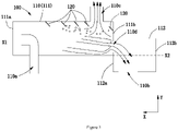
FIG. 1 is a schematic diagram of an economizer; -
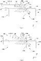
FIG. 2 is a schematic diagram of another economizer; and -
FIG. 3 is a schematic diagram of yet another economizer. - The present application will be described in detail below with reference to exemplary embodiments in the accompanying drawings. It should be understood, however, that the present application may be implemented in many different forms, and should not be construed as being limited to the embodiments set forth herein. The embodiments are herein provided to make the disclosure of the present application thorough and complete, and fully convey the concept of the present application to those skilled in the art.
- In addition, for any single technical feature described or implied in the embodiments mentioned herein, or any single technical feature shown or implied in individual drawings, the present application still allows for any combination or omission of these technical features (or equivalents thereof) without any technical obstacle, thereby obtaining further embodiments of the present application that may not be directly mentioned herein.
- For the convenience of describing the embodiments mentioned herein, the axial direction and the radial direction are introduced herein as the Reference Coordinate System. This way of describing directions aims to express the structural characteristics of the respective components and the relative positional relationships between the components, rather than restricting the absolute positional relationships thereof. Taking the housing of the economizer in
FIG. 1 as an example, the axial direction refers to the direction indicating the axis of the cylindrical housing, or the direction in which the length of the cylindrical housing extends, and the radial direction refers to the indicated direction of the cylindrical housing that is perpendicular to the axis, or the direction in which the radius of the cylindrical housing extends. In order to more clearly indicate the positional relationships, in some drawings, the X axis is used to indicate the axial direction, and more specifically, X1 and X2 are respectively used to indicate the axes of different sections of the cylindrical housing; in addition, the Y axis is used to indicate the radial direction. - Referring to
FIGS. 1 to 3 , various embodiments of the economizer according to the present application are shown. Most of the arrangements of the economizers in these embodiments are similar, the differences being mainly in the specific implementations of the choke portion. The common characteristics of these embodiments of the economizers will first be introduced below, and then the unique characteristics thereof will be described with reference to different figures. - Referring first to
FIG. 1 , aneconomizer 100 comprises ahousing 110 with arefrigerant inlet 110a, arefrigerant outlet 110b and asuction port 110c provided thereon, respectively. Wherein, therefrigerant inlet 110a is used to connect to a first heat exchanger that usually serves as a condenser, so that the two-phase refrigerant from the condenser that is flash evaporated through the high-side throttle valve is introduced into theeconomizer 100. The introduced two-phase refrigerant undergoes gas-liquid separation in the economizer. After that, the refrigerant mainly in the liquid phase will flow into a second heat exchanger that usually serves as an evaporator through therefrigerant outlet 110b, so as to perform its evaporation and heat absorption function; and the refrigerant mainly in the gas phase flows into an intermediate stage of a multistage compressor through thesuction port 110c, so as to supplement gas and add enthalpy. - In addition, the
housing 110 is also provided with achoke portion 120 configured to protrude inwardly from the inner wall of thehousing 110 and arranged close to thesuction port 110c, such that the refrigerant flowing to thesuction port 110c is at least partially obstructed. Under this arrangement, the economizer according to the present application enables, on the one hand, the refrigerant flowing from the refrigerant inlet directly to the suction port to be at least partially obstructed, and enables, on the other hand, the refrigerant flowing from the refrigerant inlet that impinges on the inner wall of the economizer housing, resulting in turbulent flow and turning back to the suction port to also be at least partially obstructed. When the liquid droplets carried by the refrigerant are obstructed by the choke portion, the liquid droplets are adsorbed on the wall surface to form a liquid film, and the movement of the liquid film is obstructed by the choke portion. Eventually, larger liquid droplets will fall off from the liquid film to the bottom of the economizer and flows into the second heat exchanger through the refrigerant outlet. As such, the number of liquid droplets that are sucked to the intermediate stage of the compressor through the suction port is reduced, which effectively alleviates the LCO problem, and improves system performance and economizer capability. - It should be noted that, regarding the expression "close to" mentioned above and as used throughout the description and the claims, it is intended to express the relative positional relationships between the components, while the specific positional definition should further be summarized according to the purpose of setting the features. For example, in the above context, the
choke portion 120 is arranged close to thesuction port 110c, which means that compared with therefrigerant inlet 110a or therefrigerant outlet 110b, thechoke portion 120 is arranged closer to thesuction port 110c on the inner wall of the housing, thereby achieving its purpose of influencing the number of liquid droplets carried in the gas-phase refrigerant flowing into thesuction port 110c. - Further modifications to the economizer will be introduced below by way of examples, so as to further improve its working efficiency, reliability, or for other improvements.
- For example, with continued reference to
FIG. 1 , in one embodiment, thehousing 110 of theeconomizer 100 is configured to comprise a firstcylindrical housing section 111 and a secondcylindrical housing section 112. The firstcylindrical housing section 111 has afirst end 111a located on the left side in the figure and asecond end 111b located on the right side in the figure, and the secondcylindrical housing section 112 has afirst end 112a located on the left side in the figure and asecond end 112b located on the right side in the figure. Wherein, the firstcylindrical housing section 111 and the secondcylindrical housing section 112 are arranged in a staggered manner in the axial direction X, that is, the axis X1 of the firstcylindrical housing section 111 and the axis X2 of the secondcylindrical housing section 112 are parallel to each other in the axial direction X and are offset from each other. Thesecond end 111b of the firstcylindrical housing section 111 is arranged adjacent to thefirst end 112a of the secondcylindrical housing section 112, and anintermediate connection port 110d is provided therebetween for communicating with the two. The port usually has a shape similar to an "eye", so it is also called an "eye hole". Wherein, therefrigerant inlet 110a is provided at the bottom of and within the firstcylindrical housing section 111, thesuction port 110c is provided at the top of and within the firstcylindrical housing section 111, and therefrigerant outlet 110b is provided at the bottom of and within the secondcylindrical housing section 112. After the refrigerant flows into the firstcylindrical housing section 111 through therefrigerant inlet 110a, a part of the gas-phase refrigerant flows into the compressor through thesuction port 110c, and the other part of the liquid-phase refrigerant flows into the secondcylindrical housing section 112 through theeye hole 110d and then flows into an evaporator that is not shown through therefrigerant outlet 110b. - For the configuration of the
economizer 100 in the aforementioned embodiment, thesuction port 110c thereof may be arranged close to theintermediate connection port 110d, and at least a portion of thechoke portion 120 may be arranged between thesuction port 110c and theintermediate connection port 110d. This is because, when the refrigerant flows from the firstcylindrical housing section 111 to the secondcylindrical housing section 112 through theintermediate connection port 110d, its flow area is reduced from a larger cross section of a cylinder to a smaller cross section of an eye hole, so the refrigerant will be partially obstructed and impacted, and then turbulent flow may occur and return to the firstcylindrical housing section 111. At this time, a part of the gas-phase refrigerant will also be sucked into thesuction port 110c. Therefore, by arranging thechoke portion 120 between the two ports, the part of returned gas-phase refrigerant can be effectively obstructed, so that the liquid droplets carried with it form a liquid film and eventually form large liquid droplets that fall off from the liquid film. As such, the number of liquid droplets sucked to the intermediate stage of the compressor is reduced, which further effectively alleviate the LCO problem, and improve the system performance and economizer capability. - Based on similar considerations, at least a portion of the
choke portion 120 may also be arranged between thesuction port 110c and therefrigerant inlet 110a, which can also effectively obstruct the gas-phase refrigerant flowing therethrough, so that the liquid droplets carried therewith will form a liquid film and eventually form large liquid droplets that fall off from the liquid film, thereby effectively alleviating the LCO problem. - For the configuration of the
economizer 100 in the aforementioned embodiment, therefrigerant inlet 110a thereof may also be arranged at thefirst end 111a of the firstcylindrical housing section 111 away from the secondcylindrical housing section 112, and the opening of therefrigerant inlet 110a faces the end wall of thefirst end 111a of the firstcylindrical housing section 111. Under this arrangement, the liquid-phase refrigerant flowing in through therefrigerant inlet 110a will first impinge on the end wall at a high speed, and then form a liquid film state, moving from left to right. When the liquid film encounters the choke portion, it is easier to form large droplets that fall off from the liquid film, which also helps to alleviate the LCO problem. - Various design modifications focusing on the
choke portion 120 will be described in detail below with reference toFIGS. 1 to 3 . - For example, taking any of the drawings as an example, at least a portion of the
choke portion 120 shown in the figure is configured as an annular protrusion protruding inwardly from the inner wall of thehousing 110 in the circumferential direction. In a one-piece setting, it has fewer solder joints, is not easy to be corroded, and has stable performance; in a split-type setting, it is easy to manufacture and assemble, and has better applicability as the specific location of the annular protrusion on the housing can be adjusted according to actual needs. - Still taking any of the drawings as an example, wherein, the length of at least a portion of the
choke portion 120 protruding inwardly from the inner wall of thehousing 110 is not greater than 5% of the diameter of thehousing 110. At this time, on the one hand, it can bring a better choking effect and effectively reduce the number of liquid droplets; on the other hand, it will not cause excessive pressure loss to the refrigerant in the economizer, so as to avoid affecting its refrigeration performance. - Taking
FIG. 1 as an example, at least a portion of thechoke portion 120 may be arranged perpendicular to the axial direction X of the inner wall of thehousing 110, which is easier to arrange. TakingFIGS. 2 and3 as examples, at least a portion of thechoke portion 120 may also be arranged to form an included angle within a range of ±45° with the axial direction X of the inner wall of thehousing 110. Wherein, when a portion of thechoke portion 120 is inclined toward the side to which the refrigerant flows (as shown inFIG. 3 ), it has a larger choking area; and when a portion of thechoke portion 120 is inclined toward the side opposite to the refrigerant flow (as shown inFIG. 2 ), it can bring a stronger choking effect. - In addition, although not shown in the figures, an embodiment of an air conditioning system according to the present application is further provided herein. The air conditioning system comprises the economizer mentioned in any of the aforementioned embodiments or combinations thereof, and thus also has the corresponding technical effects, which will not be repeated here. Furthermore, for an air conditioning system, it further comprises a multistage compressor having an intermediate stage, a condenser, and an evaporator. Under this arrangement, the
refrigerant inlet 110a of theeconomizer 100 will be connected to the condenser, therefrigerant outlet 110b of theeconomizer 100 will be connected to the evaporator, and thesuction port 110c of theeconomizer 100 will be connected to the intermediate stage of the multistage compressor, thereby achieving the suction, separation and outflow of the refrigerant. - Wherein, those skilled in the art should understand that the air conditioning system set forth in the present application does not refer to the air conditioner with indoor refrigerating/heating unit and outdoor heat exchange unit used in buildings in the industry in a narrow sense. It, however, should be understood as a type of thermal system with the function of achieving air conditioning, which, when driven by various power sources (e.g., electric power), achieves heat exchange with the air at the location to be conditioned through the phase change of the refrigerant in the system. For example, when the air conditioning system is used for building HVAC (Heating Ventilation Air Conditioning), it may be a refrigeration system with cooling function only, or it may be a heat pump system with both cooling and heating capabilities. For another example, when the air conditioning system is used in the field of cold chain, it may be a transport refrigeration system or a refrigeration/freezing system. However, no matter what form of air conditioning system it is, there should be an economizer so as to be applicable to the concept of the present application.
- A refrigeration system will be taken as an example below to describe the working process of such a refrigeration system having an economizer in any of the aforementioned embodiments or combinations thereof. First, when the work starts, the gas-phase refrigerant discharged from the multistage compressor is pressed into the condenser; the gas-phase refrigerant flows in the condenser and exchanges heat with water or other media during the flow; the cooled refrigerant passes through the condenser outlet and flows into the
housing 110 from therefrigerant inlet 110a at the bottom of thefirst end 111a of theeconomizer 100, ejecting and impinging on the end wall of thefirst end 111a and forming a liquid film, which flows from left to right in the housing in the longitudinal direction until it hits thechoke portion 120 on the upper part of the inner wall of the housing. At this time, a part of the gas-liquid two-phase refrigerant suspended in the upper part of the housing and the liquid film will be adsorbed by thechoke portion 120, and eventually form larger liquid droplets that fall off from the liquid film; and the refrigerant gas is sucked into the intermediate stage of the compressor through thesuction port 110c to achieve gas supplementation and enthalpy addition. On the other hand, when a part of the refrigerant that continues to move forward flows into the secondcylindrical housing section 112 through theintermediate connection port 110d, due to a sudden reduction of the flow area, a part of the gas-phase refrigerant carrying liquid droplets will form return flows. The returned gas-liquid two-phase refrigerant is also adsorbed by thechoke portion 120 and eventually form larger liquid droplets that fall off from the liquid film. The refrigerant gas is sucked into the intermediate stage of the compressor through thesuction port 110c to achieve gas supplementation and enthalpy addition. In addition, the liquid-phase refrigerant that flows into the secondcylindrical housing section 112 will enter the evaporator through therefrigerant outlet 110b at the bottom thehousing 110 to exchange heat therein before returning to the compressor. The reciprocating cycle of the refrigeration system goes in this way. - The above examples mainly illustrate the economizer and the air conditioning system of the present invention. Although only some of the embodiments of the present invention are described, those skilled in the art should understand that the present invention may, without departing from the scope thereof, be implemented in many other forms. Therefore, the examples and embodiments illustrated are to be considered as illustrative but not restrictive, and the present invention may cover various modifications or replacements if not departed from the scope of the present invention as defined by the appended claims.
Claims (10)
- An economizer (100), comprising:a housing (110) with a refrigerant inlet (110a) for connecting to a first heat exchanger, a refrigerant outlet (110b) for connecting to a second heat exchanger, and a suction port (110c) for connecting to an intermediate stage of a compressor provided thereon; anda choke portion (120) configured to protrude inwardly from an inner wall of the housing and arranged close to the suction port, such that refrigerant flowing to the suction port is at least partially obstructed.
- The economizer according to claim 1, wherein, the housing comprises a first cylindrical housing section (111) and a second cylindrical housing section (112) arranged in a staggered manner in an axial direction (X) and having an interconnecting intermediate connection port (110d); wherein, the refrigerant inlet and the suction port are arranged in the first cylindrical housing section, and the refrigerant outlet is arranged in the second cylindrical housing section.
- The economizer according to claim 2, wherein the suction port is arranged close to the intermediate connection port, and at least a portion of the choke portion is arranged between the suction port and the intermediate connection port.
- The economizer according to claim 2 or 3, wherein the refrigerant inlet is arranged at a first end (111a) of the first cylindrical housing section away from the second cylindrical housing section, and an opening of the refrigerant inlet faces an end wall of the first end of the first cylindrical housing section.
- The economizer according to any of claims 1 to 4, wherein at least a portion of the choke portion is configured as an annular protrusion protruding inwardly from the inner wall of the housing in a circumferential direction.
- The economizer according to any of claims 1 to 5, wherein at least a portion of the choke portion is arranged perpendicular to an axial direction (X) of the inner wall of the housing.
- The economizer according to any of claims 1 to 4, wherein at least a portion of the choke portion is arranged to form an included angle within a range of ±45° with the axial (X) direction of the housing.
- The economizer according to any of claims 1 to 7, wherein a length of at least a portion of the choke portion protruding inwardly from the inner wall of the housing is not greater than 5% of a diameter of the housing.
- The economizer according to any of claims 1 to 8, wherein at least a portion of the choke portion is arranged between the suction port and the refrigerant inlet.
- An air conditioning system, comprising:a multistage compressor having an intermediate stage;a condenser;an evaporator; andthe economizer (100) according to any of claims 1 to 9;wherein the refrigerant inlet (110a) of the economizer is connected to the condenser, the refrigerant outlet (110b) of the economizer is connected to the evaporator, and the suction port (110c) of the economizer is connected to the intermediate stage of the multistage compressor.
Applications Claiming Priority (1)
| Application Number | Priority Date | Filing Date | Title |
|---|---|---|---|
| CN202110423066.1A CN115218559B (en) | 2021-04-20 | 2021-04-20 | Economizer and air conditioning system |
Publications (1)
| Publication Number | Publication Date |
|---|---|
| EP4080141A1 true EP4080141A1 (en) | 2022-10-26 |
Family
ID=81344426
Family Applications (1)
| Application Number | Title | Priority Date | Filing Date |
|---|---|---|---|
| EP22169100.9A Pending EP4080141A1 (en) | 2021-04-20 | 2022-04-20 | Flash tank economizer and air conditioning system |
Country Status (3)
| Country | Link |
|---|---|
| US (1) | US12247767B2 (en) |
| EP (1) | EP4080141A1 (en) |
| CN (1) | CN115218559B (en) |
Citations (3)
| Publication number | Priority date | Publication date | Assignee | Title |
|---|---|---|---|---|
| JPH09250848A (en) * | 1996-03-14 | 1997-09-22 | Mitsubishi Heavy Ind Ltd | Transversely long accumulator for freezer |
| JP2000320933A (en) * | 1999-05-11 | 2000-11-24 | Mitsubishi Electric Corp | Gas-liquid separator and method of manufacturing the same |
| US20150096315A1 (en) * | 2013-10-03 | 2015-04-09 | Carrier Corporation | Flash Tank Economizer for Two Stage Centrifugal Water Chillers |
Family Cites Families (18)
| Publication number | Priority date | Publication date | Assignee | Title |
|---|---|---|---|---|
| JP2007192433A (en) * | 2006-01-17 | 2007-08-02 | Daikin Ind Ltd | Gas-liquid separator and refrigeration apparatus equipped with the gas-liquid separator |
| US20070251256A1 (en) * | 2006-03-20 | 2007-11-01 | Pham Hung M | Flash tank design and control for heat pumps |
| CN102128508B (en) * | 2010-01-19 | 2014-10-29 | 珠海格力电器股份有限公司 | Ejector throttling air supply system and heat pump or refrigeration system air supply method |
| CN202328948U (en) * | 2011-11-18 | 2012-07-11 | 珠海格力电器股份有限公司 | Power economizer, compressor and air conditioner |
| CN202598965U (en) * | 2012-04-01 | 2012-12-12 | 东莞埃欧热能技术有限公司 | All-welded economizer |
| CN102914101B (en) * | 2012-10-24 | 2015-01-21 | 重庆美的通用制冷设备有限公司 | Flash type economizer |
| CN203478735U (en) * | 2013-06-20 | 2014-03-12 | 重庆通用工业(集团)有限责任公司 | Economizer for preventing liquid from splashing |
| KR102201746B1 (en) * | 2014-05-20 | 2021-01-12 | 엘지전자 주식회사 | Economizer comprising condenser and turbo chiller comprising the same |
| US9874382B2 (en) * | 2014-07-10 | 2018-01-23 | Heatcraft Refrigeration Products Llc | Refrigeration system with full oil recovery |
| CN106352608B (en) * | 2015-07-13 | 2021-06-15 | 开利公司 | Economizer component and refrigerating system with same |
| CN117366922A (en) * | 2015-12-10 | 2024-01-09 | 开利公司 | Economizer and refrigeration system having the same |
| JP6767196B2 (en) * | 2016-08-02 | 2020-10-14 | 荏原冷熱システム株式会社 | Economizer |
| CN107421179B (en) * | 2017-05-23 | 2023-07-04 | 珠海格力电器股份有限公司 | Flash device |
| CN107388652A (en) | 2017-08-25 | 2017-11-24 | 天津商业大学 | A kind of horizontal type gas and liquid separator |
| KR101955474B1 (en) * | 2017-08-25 | 2019-03-11 | 삼성중공업 주식회사 | Economizer |
| CN208154886U (en) * | 2018-04-13 | 2018-11-27 | 重庆美的通用制冷设备有限公司 | Economizer and water cooler with it |
| CN109140836A (en) * | 2018-11-12 | 2019-01-04 | 大连冷冻机股份有限公司 | Flash Economizer for Refrigeration Units |
| CN115493317A (en) * | 2021-06-17 | 2022-12-20 | 开利公司 | Economizers for refrigeration systems and refrigeration systems |
-
2021
- 2021-04-20 CN CN202110423066.1A patent/CN115218559B/en active Active
-
2022
- 2022-04-20 US US17/725,078 patent/US12247767B2/en active Active
- 2022-04-20 EP EP22169100.9A patent/EP4080141A1/en active Pending
Patent Citations (3)
| Publication number | Priority date | Publication date | Assignee | Title |
|---|---|---|---|---|
| JPH09250848A (en) * | 1996-03-14 | 1997-09-22 | Mitsubishi Heavy Ind Ltd | Transversely long accumulator for freezer |
| JP2000320933A (en) * | 1999-05-11 | 2000-11-24 | Mitsubishi Electric Corp | Gas-liquid separator and method of manufacturing the same |
| US20150096315A1 (en) * | 2013-10-03 | 2015-04-09 | Carrier Corporation | Flash Tank Economizer for Two Stage Centrifugal Water Chillers |
Also Published As
| Publication number | Publication date |
|---|---|
| US20220333829A1 (en) | 2022-10-20 |
| CN115218559A (en) | 2022-10-21 |
| CN115218559B (en) | 2025-11-07 |
| US12247767B2 (en) | 2025-03-11 |
Similar Documents
| Publication | Publication Date | Title |
|---|---|---|
| US8439104B2 (en) | Multichannel heat exchanger with improved flow distribution | |
| EP2543941B1 (en) | Chiller | |
| CN103256757B (en) | Heat exchangers and air conditioning units | |
| US9752803B2 (en) | Heat pump system with a flow directing system | |
| US20080141709A1 (en) | Multi-Block Circuit Multichannel Heat Exchanger | |
| JP5050563B2 (en) | Ejector and ejector type refrigeration cycle unit | |
| US20090288440A1 (en) | Multichannel Heat Exchanger with Dissimilar Tube Spacing | |
| CA2596324A1 (en) | Parallel flow heat exchanger for heat pump applications | |
| EP3640549B1 (en) | Air conditioner system and air conditioner having same | |
| CN215638160U (en) | Air conditioner heat exchange system and air conditioner | |
| WO2012112802A2 (en) | Heat pump system with a flow directing system | |
| JPWO2018225252A1 (en) | Heat exchanger and refrigeration cycle device | |
| US20170356700A1 (en) | Frost tolerant microchannel heat exchanger | |
| CN112944741A (en) | A liquid drop evaporation plant and cooling water set for cooling water set | |
| US12247767B2 (en) | Economizer and air conditioning system | |
| US20170328615A1 (en) | Refrigerant evaporator | |
| CN215951838U (en) | Refrigerating system and household appliance | |
| US11898781B2 (en) | Gas header, heat exchanger, and refrigeration cycle apparatus | |
| US20180135893A1 (en) | Turbo refrigeration apparatus | |
| CN114909725B (en) | Efficient energy-saving multi-split system | |
| CN109682105B (en) | Air Conditioning System | |
| EP3945266A1 (en) | Refrigeration system and control method therefor | |
| CN221005577U (en) | Condenser and refrigerant circulation system | |
| CN115751485B (en) | Outdoor heat exchanger structure, air conditioning system including the same, and control method | |
| EP4498021A1 (en) | Air conditioning system |
Legal Events
| Date | Code | Title | Description |
|---|---|---|---|
| PUAI | Public reference made under article 153(3) epc to a published international application that has entered the european phase |
Free format text: ORIGINAL CODE: 0009012 |
|
| STAA | Information on the status of an ep patent application or granted ep patent |
Free format text: STATUS: THE APPLICATION HAS BEEN PUBLISHED |
|
| AK | Designated contracting states |
Kind code of ref document: A1 Designated state(s): AL AT BE BG CH CY CZ DE DK EE ES FI FR GB GR HR HU IE IS IT LI LT LU LV MC MK MT NL NO PL PT RO RS SE SI SK SM TR |
|
| STAA | Information on the status of an ep patent application or granted ep patent |
Free format text: STATUS: REQUEST FOR EXAMINATION WAS MADE |
|
| 17P | Request for examination filed |
Effective date: 20230426 |
|
| RBV | Designated contracting states (corrected) |
Designated state(s): AL AT BE BG CH CY CZ DE DK EE ES FI FR GB GR HR HU IE IS IT LI LT LU LV MC MK MT NL NO PL PT RO RS SE SI SK SM TR |
|
| STAA | Information on the status of an ep patent application or granted ep patent |
Free format text: STATUS: EXAMINATION IS IN PROGRESS |
|
| 17Q | First examination report despatched |
Effective date: 20240111 |