EP4080115A1 - Vertical type steam generator of pressurized water reactor nuclear power plant and loosening part capturing device therefor - Google Patents
Vertical type steam generator of pressurized water reactor nuclear power plant and loosening part capturing device therefor Download PDFInfo
- Publication number
- EP4080115A1 EP4080115A1 EP19953742.4A EP19953742A EP4080115A1 EP 4080115 A1 EP4080115 A1 EP 4080115A1 EP 19953742 A EP19953742 A EP 19953742A EP 4080115 A1 EP4080115 A1 EP 4080115A1
- Authority
- EP
- European Patent Office
- Prior art keywords
- capturing
- plate
- top plate
- steam
- steam generator
- Prior art date
- Legal status (The legal status is an assumption and is not a legal conclusion. Google has not performed a legal analysis and makes no representation as to the accuracy of the status listed.)
- Granted
Links
Images

Classifications
-
- F—MECHANICAL ENGINEERING; LIGHTING; HEATING; WEAPONS; BLASTING
- F22—STEAM GENERATION
- F22B—METHODS OF STEAM GENERATION; STEAM BOILERS
- F22B1/00—Methods of steam generation characterised by form of heating method
- F22B1/02—Methods of steam generation characterised by form of heating method by exploitation of the heat content of hot heat carriers
- F22B1/16—Methods of steam generation characterised by form of heating method by exploitation of the heat content of hot heat carriers the heat carrier being hot liquid or hot vapour, e.g. waste liquid, waste vapour
- F22B1/162—Methods of steam generation characterised by form of heating method by exploitation of the heat content of hot heat carriers the heat carrier being hot liquid or hot vapour, e.g. waste liquid, waste vapour in combination with a nuclear installation
-
- F—MECHANICAL ENGINEERING; LIGHTING; HEATING; WEAPONS; BLASTING
- F22—STEAM GENERATION
- F22B—METHODS OF STEAM GENERATION; STEAM BOILERS
- F22B37/00—Component parts or details of steam boilers
- F22B37/002—Component parts or details of steam boilers specially adapted for nuclear steam generators, e.g. maintenance, repairing or inspecting equipment not otherwise provided for
-
- F—MECHANICAL ENGINEERING; LIGHTING; HEATING; WEAPONS; BLASTING
- F22—STEAM GENERATION
- F22B—METHODS OF STEAM GENERATION; STEAM BOILERS
- F22B37/00—Component parts or details of steam boilers
- F22B37/02—Component parts or details of steam boilers applicable to more than one kind or type of steam boiler
- F22B37/22—Drums; Headers; Accessories therefor
- F22B37/225—Arrangements on drums or collectors for fixing tubes or for connecting collectors to each other
-
- F—MECHANICAL ENGINEERING; LIGHTING; HEATING; WEAPONS; BLASTING
- F22—STEAM GENERATION
- F22B—METHODS OF STEAM GENERATION; STEAM BOILERS
- F22B37/00—Component parts or details of steam boilers
- F22B37/02—Component parts or details of steam boilers applicable to more than one kind or type of steam boiler
- F22B37/26—Steam-separating arrangements
- F22B37/268—Steam-separating arrangements specially adapted for steam generators of nuclear power plants
-
- F—MECHANICAL ENGINEERING; LIGHTING; HEATING; WEAPONS; BLASTING
- F22—STEAM GENERATION
- F22B—METHODS OF STEAM GENERATION; STEAM BOILERS
- F22B37/00—Component parts or details of steam boilers
- F22B37/02—Component parts or details of steam boilers applicable to more than one kind or type of steam boiler
- F22B37/48—Devices or arrangements for removing water, minerals or sludge from boilers ; Arrangement of cleaning apparatus in boilers; Combinations thereof with boilers
- F22B37/483—Devices or arrangements for removing water, minerals or sludge from boilers ; Arrangement of cleaning apparatus in boilers; Combinations thereof with boilers specially adapted for nuclear steam generators
Definitions
- the present invention generally relates to nuclear power plants, and more particularly, relates to a vertical type steam generator of a pressurized water reactor nuclear power plant and loosing part capturing device therefor.
- Steam generator is the hub of the primary and secondary circuits of the nuclear power plant, which is used to transfer the heat generated by the reactor to the secondary side to generate steam, and transport the steam to the steam turbine to drive the generator to generate electricity.
- the pressure boundary of primary side of the steam generator includes a lower head, a pipe plate and a pipe bundle, wherein the lower head is divided into an inlet water chamber and an outlet water chamber by a separating plate, and the reactor coolant enters through an inlet connecting pipe located on the lower head of the steam generator, flows through the U-shaped heat transfer pipe, and then flows out through the outlet connecting pipeon the lower head.
- the pressure boundary of the secondary side of the steam generator includes the pipe plate, the lower cylinder, the conical cylinder, the upper cylinder and the upper head.
- the water enters the steam generator via the water supply pipe, enters the water supply ring pipe after passing through the water supply pipe, and is sprayed via the nozzles on the water supply ring pipe. After mixed with the saturated water seperated from the steam and water separating device, the water flows into an annular descending channel between the pipe bundle sleeve and the housing, and reaches the secondary side surface of the pipe plate.
- the water enters the pipe bundle through the gap between the lower end of the sleeve and the secondary side surface of the pipe plate, and the water is heated as it rises through the pipe bundle, and part of the water turns into steam, thereby forming a steam-water mixture.
- the steam-water mixture flows out of the top of the pipe bundle, it enters the steam and water separator for coarse separation, enters the dryer for fine separation, and finally outputs dry saturated steam.
- Heat transfer pipes of the steam generator constitute the pressure-bearing boundary between the primary and secondary sides, and undertake the function of isolating the radioactive substances of the primary circuit coolant of the reactor.
- the heat transfer pipe is a seamless steel tube with a wall thickness of about 1mm. The integrity of the heat transfer pipe must be guaranteed to prevent the heat transfer pipe from breaking and leaking and causing serious contamination of the secondary circuit system.
- loosening parts entering the steam generator via the water supply system can cause damage to the heat transfer pipes.
- the loosening parts vary in size and can enter the steam generator via the J-shaped pipe or spray head on the water supply ring pipe. Under the action of the fluid, the loosening parts enter the descending channel and contact the heat transfer pipes via the opening between the bottom of the pipe bundle sleeve and the pipe sheet, thereby forming dents or continuous impact marks on the surface of the heat transfer pipes.
- Loosening parts smaller than the gap of the heat transfer pipes may enter the inside of the pipe bundle and stay in the relative stagnation area of the fluid.
- the conventional devices for preventing foreign matter from entering the steam generator mainly adopt the screening method, i.e., setting a small diameter J-shaped pipe or an I-shaped pipe with spray holes on the water supply ring pipe.
- the screening method i.e., setting a small diameter J-shaped pipe or an I-shaped pipe with spray holes on the water supply ring pipe.
- One object of the present invention is to overcome the disadvantages in the prior art, and to provide a reliable vertical type steam generator of the pressurized water reactor nuclear power plant and a loosening part capturing device thereof, which can collect the loosening parts entering the steam generator through the water supply ring pipe during the commissioning and operation of the nuclear power plant, prevent the loosening parts from entering the pipe bundle area, and improve the working environment of the heat transfer pipe.
- a loosening part capturing device for a steam generator of a pressurized water reactor nuclear power plant is arranged on a top plate of a sludge collector, the top plate being provided with a plurality of steam and water separator rising cylinder, wherein capturing enclosing plates fixedly connected to the top plate are provided between every adjacent steam and water separator rising cylinders on the periphery of the top plate, two ends of each capturing enclosing plate are respectively fixedly connected to outer surfaces of the steam and water separator rising cylinders, and one end of each capturing enclosing plates afar from the top plate is provided with a folding plate extending towards a center of the top plate.
- the capturing enclosing plates are welded on the top plate, and two ends of the capturing enclosing plates are respectively welded on outer surfaces of the steam and water separator rising cylinders.
- an arc transition is provided between the folding plate and the capturing enclosing plate, and the arc transition has a transition radius of 5-25mm.
- an angle between the folding plate and the capturing enclosing plate is 30-150 degrees.
- the top plate is provided with center holes and circumferential holes, the capturing enclosing plates are located inside the circumferential holes.
- a radius of a projection of the capturing enclosing plate and the folding plate on the top plate is larger than a radius of a projection of a water supply loop spray pipe or a J-shaped pipe of the steam generator.
- a vertical type steam generator of a pressurized water reactor nuclear power plant including an upper dish-shaped head, an upper cylinder, a conical cylinder, a lower cylinder, a pipe plate and a lower head, the pipe plate being provided with a number of pipe holes, two ends of inverted U-shaped pipe bundle being inserted into the pipe holes and mechanically assembled to the pipe plate to form a pipe bundle havinging a number of inverted U-shaped tubes, the pipe bundle being provided with a sleeve at a periphery thereof and a sleeve top cover thereon, the sleeve, the lower cylinder and the conical cylinder jointly defining an annular channel, wherein the sleeve top cover is provied with a sludge collector, the top plate of the sludge collector is provided with a plurality of steam and water separator rising cylinder and capturing enclosing plates, capturing enclosing plates are arrange between every adjacent steam and water separat
- the capturing enclosing plates are welded on the top plate, and two ends of the capturing enclosing plates are respectively welded on outer surfaces of the steam and water separator rising cylinder.
- the sleeve top cover is provided with holes correspondingly connected with a group of steam and water separator rising cylinders, and the steam and water separator rising cylinders each is provided with rotary blades therein, and steam-water two-phase mixture generated by boiling inside the sleeve flows through the holes of the top plate and enters the steam and water separator rising cylinders, the steam and water undergo a spiral centrifugal motion under the action of the rotary blades, and the steam and water are separated under the centrifugal force.
- separated water re-enters a pool provided above the sleeve top cover, and wet steam separated by a primary separator continues to flow upward and is separated and dried again by a dryer, and the steam after secondary separation flows out of the steam generator through a current limiter arranged in a center of the upper dish-shaped head.
- recirculating water separated from the steam-water separator is mixed with a water supply pipe and enters the annular channel, and there is a pressure difference between the central area and the peripheral circumferential area of the top plate due to a relatively large fluid flow velocity in the annular channel and a relatively small fluid flow velocity in the central area above the sleeve top cover.
- a water supply pipe is provided above the sludge collector, and the water supply pipe has an approximate circular structure, and a diameter of the water supply pipe is smaller than that of the sleeve top cover arranged horizontally inside the steam generator.
- an arc transition is provided between the folding plate and the capturing enclosing plate, and the arc transition has a transition radius of 5-25mm.
- an angle between the folding plate and the capturing enclosing plates is 30 to 150 degrees.
- the top plate is provided with center holes and circumferential holes, and the capturing enclosing plates are located inside the circumferential holes.
- a radius of a projection of the capturing enclosing plate and the folding plate on the top plate is larger than a radius of a projection of a water supply loop spray pipe or a J-shaped pipe provided by the steam generator.
- the vertical type steam generator of a pressurized water reactor nuclear power plant and loosing part capturing device therefor of the present invention has the following advantages: during the refueling period, the water on the secondary side of the steam generator will be emptied, the capturing enclosing plate and the foling plate can capture the loosening parts on the top plate, to prevent the loosening parts from migrating into the annular channel under the action of fluid.
- the steam generator is emptied, the water in the area enclosed by the the capturing enclosing plate and the foling plate can be emptied through the small holes in the central area of the top plate of the sludge collector, which will not affect the in-service work of the top plate of the sludge collector.
- the capturing enclosing plate and the foling plate can capture the loosening parts on the top plate, so as to avoid migration into the annular channel under the action of the fluid, thereby realizing reliable operation of the vertical type steam generator of a pressurized water reactor nuclear power plant.
- Fig. 1 is a schematic structural diagram of a vertical type steam generator 10 of a pressurized water reactor nuclear power plant according to one embodiment of the present invention.
- the steam generator 10 is a vertical type shell and pipe heat exchanger including an upper dish-shaped head 12, an upper cylinder 13, a conical cylinder 14, a lower cylinder 15, a pipe plate 16 and a lower head 17.
- the pipe plate 16 is provided with thousands of pipe holes 18, and two ends of the inverted U-shaped pipe bundle 11 are inserted into the pipe holes 18 and are mechanically connected to the pipe plate 16.
- the pipe bundle 11 forms a heat transfer surface that exchanges heat with the primary circuit, so that the heat of the primary circuit coolant is transferred to the secondary side, and the water on the secondary side is boiled to generate steam.
- the seperating plate 19 divides the interior of the lower head 17 into a first chamber 20 and a second chamber 21, forming a pipe header of an inverted U-shaped pipe.
- the first chamber 20 is the primary side fluid inlet chamber, which is connected to the inlet connecting pipe 22.
- the second chamber 21 is the primary side fluid outlet chamber, which is connected to the outlet connecting pipe 23. Therefore, the primary side coolant of the reactor enters the first chamber 20 from the inlet connecting pipe 22, enters the second chamber 21 through the pipes of the inverted U-shaped pipe bundle 11, and flows out of the steam generator 10 through the outlet connecting pipe 23.
- a sleeve 30 is provided on the periphery of the pipe bundle 11.
- the sleeve 30, the lower cylinder 15 and the conical cylinder 14 form an annular channel 31.
- the top of the sleeve 30 is provided with a sludge collector 50.
- the sludge collector 50 is provided with a set of holes 40.
- the holes 40 are correspondingly connected to a set of steam and water separator rising cylinder 41, and the rising cylinders 41 are provided with rotary blades 42.
- the steam-water two-phase mixture generated by the boiling inside the sleeve 30 flows through the holes 40 on the sleeve top cover 32 and enters the rising cylinder 41.
- the water supply pipe 70 includes a water supply ring pipe assembly 71 and a thermowell assembly 72.
- the water supply ring pipe assembly 71 is located above the thermowell assembly 71, to reduce the thermal stratification effect of the fluid in the pipe.
- the water supply ring pipe assembly 71 has an approximately circular structure and is horizontally arranged inside the steam generator 10.
- the water supply nozzles 73 are welded on the water supply ring pipe assembly 71, and the number of the holes 40 and the nozzles 73 is calculated and determined according to the flow rate of the main water supply.
- the nozzle 73 is provided with a large number of nozzle holes, and the diameter of the nozzle holes is 5-9 mm.
- the water level in the steam generator 10 needs to ensure that the water supply outlet is submerged.
- the main water supply of the steam generator 10 enters the fluid channel 71a in the water supply ring pipe assembly 71 from the fluid channel 72a in the thermowell assembly 72, and flows into the steam generator 10 through the fluid channel 73a inside the nozzle.
- the foreign matter entering the water supply can be intercepted by the opening, and the foreign matter larger than the inner diameter of the opening of the nozzle will not enter the steam generator 10.
- the main water supply entering the steam generator10 via the water supply ring is mixed with the recycled water separated by the separator and the dryer and enters the annular channel 31, enters the pipe bundle 11 through the opening 33 at the bottom of the sleeve 30, and generates steam by heating and boiling.
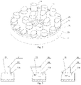
- Fig. 2 is a schematic structural diagram of a sludge collector collector 50.
- the top plate 51 of the sludge collector 50 is provided with a large number of small center holes 51a in the central area, small circumferential holes 51b in the peripheral peripheral area, and a nunber of steam and water separator rising cylinders 41.
- the recirculated water separated from the steam-water separator enters the outer space of the rising cylinder 41 of the steam-water separator, and most of the recirculated water is mixed with the water supply from the water supply pipe 70 and enters the annular channel 31.
- the fluid flow velocity of the annular channel 31 is relatively large, the fluid flow velocity above the sleeve top cover 32 is relatively slow, and there is a pressure difference between the central region and the peripheral circumferential region of the top plate 51.
- the existence of the above-mentioned pressure difference causes a part of the recirculating water to enter the sludge collector 50 from the small center holes 51a in the central region of the top plate 51, and flow out from the small circumferential holes 51b in the peripheral peripheral region.
- the recirculating water flows radially from the center in the direction of increasing radius, and the fluid velocity gradually decreases, so that the sludge particles suspended in the recirculating water are deposited on the inside surface of the sludge collector 50, thereby realizing passive deposition of the sludge.
- Capturing enclosing plates 80 are provided between every adjacent steam and water separator rising cylinders 41 located on the periphery.
- the capturing enclosing plate 80 is welded on the top plate 51, and two ends of the capturing enclosing plate 80 are welded on the outer surface of the steam and water separator rising cylinders 41 (other fastening methods can be used, such as screw connection or riveting).
- other fastening methods can be used, such as screw connection or riveting.
- One end of the capturing enclosing plate 80 afar from the top plate 51 is provided with a folding plate 81 extending toward the center of the top cover of the sludge collector 50.
- a folding plate 81 may also be provided between the folding plate 81 and the capturing enclosing plate 80, and the arc transition has a transition radius of 5-25mm.
- FIG. 3 is a schematic structural diagram of the loosening parts capturing device.
- the loosening parts capturing device is set up on the top plate of the sludge collector 50, and includes a capturing enclosing plate 80 and a folding plate 81 connected thereto.
- the folding plate 81 extends toward the center of the top plate 51 of the sludge collector 50.
- the capturing enclosing plate 80 is located inside the circumferential holes 51b of the top plate 51 of the sludge collector 50. Therefore, the setting of the capturing enclosing plate 80 does not affect the pressure difference between the central area 51a and the peripheral peripheral area 51b of the top plate 51, and does not affect normal functioning of the sludge collector 50.
- the vertical type steam generator of a pressurized water reactor nuclear power plant and loosing part capturing device therefor of the present invention has the following advantages:
- the radius of a projection of the capturing enclosing plate 80 and the folding plate 81 on the top plate 51 is larger than a radius of a projection of a water supply loop spray pipe or a J-shaped pipe of the steam generator 10.
- the fluid velocity in the center of the pool above the sludge collector 50 is relatively small, when foreign matter (such as metal rods, welding rods, and metal sheets) having a size smaller than the inner diameter of the J-shaped pipe or the diameter of the spray hole, enters the steam generator 10, the foreign matter either settles on the top plate 51 under the action of gravity or captured by the capturing enclosing plate 80 and the folding plate 81 before migrating to the annular channel31.
- foreign matter such as metal rods, welding rods, and metal sheets
- the water on the secondary side of the steam generator 10 will be emptied, and the capturing enclosing plate 80 and the folding plate 81 can capture the loosening parts on the top plate 51, to prevent the loosening parts from migrating into the annular channel 31 under the action of fluid.
- the steam generator 10 is emptied, the water in the area enclosed by the capturing enclosing plate 80 and the folding plate 81 can be emptied through the small center holes 51a in the central area of the top plate 51 of the sludge collector 50, which will not affect the operation of the top plate 51 of the sludge collector 50.
- the capturing enclosing plate 80 and the folding plate 81 can capture the loosening parts on the top plate 51, to prevent the loosening parts from migrating into the annular channel 31 under the action of the fluid.
Landscapes
- Engineering & Computer Science (AREA)
- Physics & Mathematics (AREA)
- Thermal Sciences (AREA)
- Mechanical Engineering (AREA)
- General Engineering & Computer Science (AREA)
- High Energy & Nuclear Physics (AREA)
- Life Sciences & Earth Sciences (AREA)
- Sustainable Development (AREA)
- Sustainable Energy (AREA)
- Heat-Exchange Devices With Radiators And Conduit Assemblies (AREA)
- Separating Particles In Gases By Inertia (AREA)
Abstract
Description
- The present invention generally relates to nuclear power plants, and more particularly, relates to a vertical type steam generator of a pressurized water reactor nuclear power plant and loosing part capturing device therefor.
- Steam generator is the hub of the primary and secondary circuits of the nuclear power plant, which is used to transfer the heat generated by the reactor to the secondary side to generate steam, and transport the steam to the steam turbine to drive the generator to generate electricity.
- The pressure boundary of primary side of the steam generator includes a lower head, a pipe plate and a pipe bundle, wherein the lower head is divided into an inlet water chamber and an outlet water chamber by a separating plate, and the reactor coolant enters through an inlet connecting pipe located on the lower head of the steam generator, flows through the U-shaped heat transfer pipe, and then flows out through the outlet connecting pipeon the lower head.
- The pressure boundary of the secondary side of the steam generator includes the pipe plate, the lower cylinder, the conical cylinder, the upper cylinder and the upper head. The water enters the steam generator via the water supply pipe, enters the water supply ring pipe after passing through the water supply pipe, and is sprayed via the nozzles on the water supply ring pipe. After mixed with the saturated water seperated from the steam and water separating device, the water flows into an annular descending channel between the pipe bundle sleeve and the housing, and reaches the secondary side surface of the pipe plate. The water enters the pipe bundle through the gap between the lower end of the sleeve and the secondary side surface of the pipe plate, and the water is heated as it rises through the pipe bundle, and part of the water turns into steam, thereby forming a steam-water mixture. After the steam-water mixture flows out of the top of the pipe bundle, it enters the steam and water separator for coarse separation, enters the dryer for fine separation, and finally outputs dry saturated steam.
- Heat transfer pipes of the steam generator constitute the pressure-bearing boundary between the primary and secondary sides, and undertake the function of isolating the radioactive substances of the primary circuit coolant of the reactor. The heat transfer pipe is a seamless steel tube with a wall thickness of about 1mm. The integrity of the heat transfer pipe must be guaranteed to prevent the heat transfer pipe from breaking and leaking and causing serious contamination of the secondary circuit system.
- It is well known that, loosening parts entering the steam generator via the water supply system can cause damage to the heat transfer pipes. The loosening parts vary in size and can enter the steam generator via the J-shaped pipe or spray head on the water supply ring pipe. Under the action of the fluid, the loosening parts enter the descending channel and contact the heat transfer pipes via the opening between the bottom of the pipe bundle sleeve and the pipe sheet, thereby forming dents or continuous impact marks on the surface of the heat transfer pipes. Loosening parts smaller than the gap of the heat transfer pipes may enter the inside of the pipe bundle and stay in the relative stagnation area of the fluid. The remaining loosening parts move with high frequency and small amplitude under the micro-force of the fluid, causing fretting wear on the heat transfer pipes, thereby resulting in reduction of thickness of the pipe wall. Impact dents and fretting wear can, in severe cases, cause heat transfer pipes to rupture, causing unplanned shutdowns of nuclear power plants that require costly repairs. Therefore, it is necessary to provide a device to prevent foreign loosening parts from entering the steam generator and to prevent the entered loosening parts from migrating to the pipe bundle.
- At present, the conventional devices for preventing foreign matter from entering the steam generator mainly adopt the screening method, i.e., setting a small diameter J-shaped pipe or an I-shaped pipe with spray holes on the water supply ring pipe. When the size of foreign matter is larger than the inner diameter of the J-shaped pipe or the diameter of the spray hole, it can be intercepted in the water supply pipe. However, foreign objects smaller than the inner diameter of the J-shaped pipe or the diameter of the spray hole can still pass through and enter the steam generator. The loosening parts, such as metal strips, welding rods and metal sheets, may still threat the integrity of the heat transfer pipe.
- In view of the foregoing, what is needed therefore is to provide a reliable vertical type steam generator of the pressurized water reactor nuclear power plant and a loosening part capturing device thereof, which can collect the loosening parts entering the steam generator through the water supply ring pipe during the commissioning and operation of the nuclear power plant, prevent the loosening parts from entering the pipe bundle area, and improve the working environment of the heat transfer pipe.
- One object of the present invention is to overcome the disadvantages in the prior art, and to provide a reliable vertical type steam generator of the pressurized water reactor nuclear power plant and a loosening part capturing device thereof, which can collect the loosening parts entering the steam generator through the water supply ring pipe during the commissioning and operation of the nuclear power plant, prevent the loosening parts from entering the pipe bundle area, and improve the working environment of the heat transfer pipe.
- According to one embodiment of the present invention, a loosening part capturing device for a steam generator of a pressurized water reactor nuclear power plant is arranged on a top plate of a sludge collector, the top plate being provided with a plurality of steam and water separator rising cylinder, wherein capturing enclosing plates fixedly connected to the top plate are provided between every adjacent steam and water separator rising cylinders on the periphery of the top plate, two ends of each capturing enclosing plate are respectively fixedly connected to outer surfaces of the steam and water separator rising cylinders, and one end of each capturing enclosing plates afar from the top plate is provided with a folding plate extending towards a center of the top plate.
- According to one aspect of the present invention, the capturing enclosing plates are welded on the top plate, and two ends of the capturing enclosing plates are respectively welded on outer surfaces of the steam and water separator rising cylinders.
- According to one aspect of the present invention, an arc transition is provided between the folding plate and the capturing enclosing plate, and the arc transition has a transition radius of 5-25mm.
- According to one aspect of the present invention, an angle between the folding plate and the capturing enclosing plate is 30-150 degrees.
- According to one aspect of the present invention, the top plate is provided with center holes and circumferential holes, the capturing enclosing plates are located inside the circumferential holes.
- According to one aspect of the present invention, a radius of a projection of the capturing enclosing plate and the folding plate on the top plate is larger than a radius of a projection of a water supply loop spray pipe or a J-shaped pipe of the steam generator.
- According to another embodiment of the present invention, a vertical type steam generator of a pressurized water reactor nuclear power plant, including an upper dish-shaped head, an upper cylinder, a conical cylinder, a lower cylinder, a pipe plate and a lower head, the pipe plate being provided with a number of pipe holes, two ends of inverted U-shaped pipe bundle being inserted into the pipe holes and mechanically assembled to the pipe plate to form a pipe bundle havinging a number of inverted U-shaped tubes, the pipe bundle being provided with a sleeve at a periphery thereof and a sleeve top cover thereon, the sleeve, the lower cylinder and the conical cylinder jointly defining an annular channel, wherein the sleeve top cover is provied with a sludge collector, the top plate of the sludge collector is provided with a plurality of steam and water separator rising cylinder and capturing enclosing plates, capturing enclosing plates are arrange between every adjacent steam and water separator rising cylinders on the periphery of the top plate, two ends of each capturing enclosing plate are respectively fixedly connected to outer surfaces of the separator rising cylinders, and one end of each capturing enclosing plates afar from the top plate is provided with a folding plate extending towards a center of the top plate.
- According to one aspect of the present invention, the capturing enclosing plates are welded on the top plate, and two ends of the capturing enclosing plates are respectively welded on outer surfaces of the steam and water separator rising cylinder.
- According to one aspect of the present invention, the sleeve top cover is provided with holes correspondingly connected with a group of steam and water separator rising cylinders, and the steam and water separator rising cylinders each is provided with rotary blades therein, and steam-water two-phase mixture generated by boiling inside the sleeve flows through the holes of the top plate and enters the steam and water separator rising cylinders, the steam and water undergo a spiral centrifugal motion under the action of the rotary blades, and the steam and water are separated under the centrifugal force.
- According to one aspect of the present invention, separated water re-enters a pool provided above the sleeve top cover, and wet steam separated by a primary separator continues to flow upward and is separated and dried again by a dryer, and the steam after secondary separation flows out of the steam generator through a current limiter arranged in a center of the upper dish-shaped head.
- According to one aspect of the present invention, recirculating water separated from the steam-water separator is mixed with a water supply pipe and enters the annular channel, and there is a pressure difference between the central area and the peripheral circumferential area of the top plate due to a relatively large fluid flow velocity in the annular channel and a relatively small fluid flow velocity in the central area above the sleeve top cover.
- According to one aspect of the present invention, a water supply pipe is provided above the sludge collector, and the water supply pipe has an approximate circular structure, and a diameter of the water supply pipe is smaller than that of the sleeve top cover arranged horizontally inside the steam generator.
- According to one aspect of the present invention, an arc transition is provided between the folding plate and the capturing enclosing plate, and the arc transition has a transition radius of 5-25mm.
- According to one aspect of the present invention, an angle between the folding plate and the capturing enclosing plates is 30 to 150 degrees.
- According to one aspect of the present invention, the top plate is provided with center holes and circumferential holes, and the capturing enclosing plates are located inside the circumferential holes.
- According to one aspect of the present invention, a radius of a projection of the capturing enclosing plate and the folding plate on the top plate is larger than a radius of a projection of a water supply loop spray pipe or a J-shaped pipe provided by the steam generator.
- Compared with the prior art, the vertical type steam generator of a pressurized water reactor nuclear power plant and loosing part capturing device therefor of the present invention has the following advantages: during the refueling period, the water on the secondary side of the steam generator will be emptied, the capturing enclosing plate and the foling plate can capture the loosening parts on the top plate, to prevent the loosening parts from migrating into the annular channel under the action of fluid. When the steam generator is emptied, the water in the area enclosed by the the capturing enclosing plate and the foling plate can be emptied through the small holes in the central area of the top plate of the sludge collector, which will not affect the in-service work of the top plate of the sludge collector. When water is injected into the empty steam generator, the capturing enclosing plate and the foling plate can capture the loosening parts on the top plate, so as to avoid migration into the annular channel under the action of the fluid, thereby realizing reliable operation of the vertical type steam generator of a pressurized water reactor nuclear power plant.
- The vertical type steam generator of a pressurized water reactor nuclear power plant and loosing part capturing device therefor and the technical effects thereof of the present invention will be described in detail with reference to the accompanying drawings and specific embodiments, in which:
-
Fig. 1 is a schematic structural diagram of a vertical type steam generator of a pressurized water reactor nuclear power plant according to one embodiment of the present invention; -
Fig. 2 is a schematic structural diagram of a sludge collector inFig. 1 ; and -
Fig. 3 is a schematic structural diagram of three different embodiments of the loosening parts capturing device inFig. 2 . - In order to make the objects, technical solutions and technical effects of the present invention clearer, the present invention will be further described in detail below with reference to the specific embodiments and drawings. It should be understood that the specific embodiments described in the specification are only for explaining the present invention, rather than for limiting the present invention.
- Referring to
Fig. 1 , which is a schematic structural diagram of a verticaltype steam generator 10 of a pressurized water reactor nuclear power plant according to one embodiment of the present invention. In the illustrated embodiment, thesteam generator 10 is a vertical type shell and pipe heat exchanger including an upper dish-shaped head 12, anupper cylinder 13, aconical cylinder 14, alower cylinder 15, apipe plate 16 and alower head 17. - The
pipe plate 16 is provided with thousands ofpipe holes 18, and two ends of the invertedU-shaped pipe bundle 11 are inserted into thepipe holes 18 and are mechanically connected to thepipe plate 16. Thepipe bundle 11 forms a heat transfer surface that exchanges heat with the primary circuit, so that the heat of the primary circuit coolant is transferred to the secondary side, and the water on the secondary side is boiled to generate steam. - The
seperating plate 19 divides the interior of thelower head 17 into a first chamber 20 and a second chamber 21, forming a pipe header of an inverted U-shaped pipe. The first chamber 20 is the primary side fluid inlet chamber, which is connected to the inlet connecting pipe 22. The second chamber 21 is the primary side fluid outlet chamber, which is connected to the outlet connecting pipe 23. Therefore, the primary side coolant of the reactor enters the first chamber 20 from the inlet connecting pipe 22, enters the second chamber 21 through the pipes of the invertedU-shaped pipe bundle 11, and flows out of thesteam generator 10 through the outlet connecting pipe 23. - A
sleeve 30 is provided on the periphery of thepipe bundle 11. Thesleeve 30, thelower cylinder 15 and theconical cylinder 14 form anannular channel 31. The top of thesleeve 30 is provided with asludge collector 50. Thesludge collector 50 is provided with a set ofholes 40. Theholes 40 are correspondingly connected to a set of steam and waterseparator rising cylinder 41, and the risingcylinders 41 are provided withrotary blades 42. The steam-water two-phase mixture generated by the boiling inside thesleeve 30 flows through theholes 40 on thesleeve top cover 32 and enters the risingcylinder 41. Spiral centrifugal motion of the steam-water occurs under the action of therotary blades 42. The steam and water separate under the action of the centrifugal force. The separated water re-enters the pool above thesludge collector 50. The wet steam separated by the primary separator continues to flow upward through thedryer 60 for separation and drying again, and the steam after secondary separation flows out of thesteam generator 10 through thecurrent limiter 90 arranged in the center of the upper dish-shapedhead 12. - The
water supply pipe 70 includes a water supplyring pipe assembly 71 and athermowell assembly 72. The water supplyring pipe assembly 71 is located above thethermowell assembly 71, to reduce the thermal stratification effect of the fluid in the pipe. The water supplyring pipe assembly 71 has an approximately circular structure and is horizontally arranged inside thesteam generator 10. Thewater supply nozzles 73 are welded on the water supplyring pipe assembly 71, and the number of theholes 40 and thenozzles 73 is calculated and determined according to the flow rate of the main water supply. Thenozzle 73 is provided with a large number of nozzle holes, and the diameter of the nozzle holes is 5-9 mm. - Under normal operation and normal operation transient conditions of the
steam generator 10, the water level in thesteam generator 10 needs to ensure that the water supply outlet is submerged. The main water supply of thesteam generator 10 enters thefluid channel 71a in the water supplyring pipe assembly 71 from thefluid channel 72a in thethermowell assembly 72, and flows into thesteam generator 10 through thefluid channel 73a inside the nozzle. At the same time, due to the small diameter of the opening of the nozzle, the foreign matter entering the water supply can be intercepted by the opening, and the foreign matter larger than the inner diameter of the opening of the nozzle will not enter thesteam generator 10. The main water supply entering the steam generator10 via the water supply ring is mixed with the recycled water separated by the separator and the dryer and enters theannular channel 31, enters thepipe bundle 11 through theopening 33 at the bottom of thesleeve 30, and generates steam by heating and boiling. - Referring to
Fig. 2 , which is a schematic structural diagram of asludge collector collector 50. Thetop plate 51 of thesludge collector 50 is provided with a large number ofsmall center holes 51a in the central area, smallcircumferential holes 51b in the peripheral peripheral area, and a nunber of steam and waterseparator rising cylinders 41. The recirculated water separated from the steam-water separator enters the outer space of the risingcylinder 41 of the steam-water separator, and most of the recirculated water is mixed with the water supply from thewater supply pipe 70 and enters theannular channel 31. The fluid flow velocity of theannular channel 31 is relatively large, the fluid flow velocity above thesleeve top cover 32 is relatively slow, and there is a pressure difference between the central region and the peripheral circumferential region of thetop plate 51. The existence of the above-mentioned pressure difference causes a part of the recirculating water to enter thesludge collector 50 from thesmall center holes 51a in the central region of thetop plate 51, and flow out from the smallcircumferential holes 51b in the peripheral peripheral region. Inside thesludge collector 50, the recirculating water flows radially from the center in the direction of increasing radius, and the fluid velocity gradually decreases, so that the sludge particles suspended in the recirculating water are deposited on the inside surface of thesludge collector 50, thereby realizing passive deposition of the sludge. - Capturing enclosing
plates 80 are provided between every adjacent steam and waterseparator rising cylinders 41 located on the periphery. Thecapturing enclosing plate 80 is welded on thetop plate 51, and two ends of thecapturing enclosing plate 80 are welded on the outer surface of the steam and water separator rising cylinders 41 (other fastening methods can be used, such as screw connection or riveting). In this way, the steam and waterseparator rising cylinders 41 and thecapturing enclosing plate 80 on the periphery of thesteam generator 10 are jointly enclosed around the outer periphery of thetop plate 51 of thesludge collector 50. One end of thecapturing enclosing plate 80 afar from thetop plate 51 is provided with afolding plate 81 extending toward the center of the top cover of thesludge collector 50. In other embodiments of the present invention, an arc transition may also be provided between thefolding plate 81 and thecapturing enclosing plate 80, and the arc transition has a transition radius of 5-25mm. - Referring to
Fig. 3 , which is a schematic structural diagram of the loosening parts capturing device. The loosening parts capturing device is set up on the top plate of thesludge collector 50, and includes acapturing enclosing plate 80 and afolding plate 81 connected thereto. Thefolding plate 81 extends toward the center of thetop plate 51 of thesludge collector 50. Thecapturing enclosing plate 80 is located inside thecircumferential holes 51b of thetop plate 51 of thesludge collector 50. Therefore, the setting of thecapturing enclosing plate 80 does not affect the pressure difference between thecentral area 51a and the peripheralperipheral area 51b of thetop plate 51, and does not affect normal functioning of thesludge collector 50. - Compared with the prior art, the vertical type steam generator of a pressurized water reactor nuclear power plant and loosing part capturing device therefor of the present invention has the following advantages:
The radius of a projection of thecapturing enclosing plate 80 and thefolding plate 81 on thetop plate 51 is larger than a radius of a projection of a water supply loop spray pipe or a J-shaped pipe of thesteam generator 10. Since the fluid velocity in the center of the pool above thesludge collector 50 is relatively small, when foreign matter (such as metal rods, welding rods, and metal sheets) having a size smaller than the inner diameter of the J-shaped pipe or the diameter of the spray hole, enters thesteam generator 10, the foreign matter either settles on thetop plate 51 under the action of gravity or captured by thecapturing enclosing plate 80 and thefolding plate 81 before migrating to the annular channel31. - During the refueling period, the water on the secondary side of the
steam generator 10 will be emptied, and thecapturing enclosing plate 80 and thefolding plate 81 can capture the loosening parts on thetop plate 51, to prevent the loosening parts from migrating into theannular channel 31 under the action of fluid. When thesteam generator 10 is emptied, the water in the area enclosed by thecapturing enclosing plate 80 and thefolding plate 81 can be emptied through thesmall center holes 51a in the central area of thetop plate 51 of thesludge collector 50, which will not affect the operation of thetop plate 51 of thesludge collector 50. When water is poured into theempty steam generator 10, thecapturing enclosing plate 80 and thefolding plate 81 can capture the loosening parts on thetop plate 51, to prevent the loosening parts from migrating into theannular channel 31 under the action of the fluid. - The above described embodiments are only preferred embodiments of the present invention, and are not intended to limit the scope of the present invention. Any modification, equivalent replacement and improvement within the spirit and principle of the present invention should be included in the protection scope of the present invention.
Claims (16)
- A loosening part capturing device for a steam generator (10) of a pressurized water reactor nuclear power plant, arranged on a top plate (51) of a sludge collector (50), the top plate (51) being provided with a plurality of steam and water separator rising cylinder (41), characterized in that, capturing enclosing plates (80) fixedly connected to the top plate (51) are provided between every adjacent steam and water separator rising cylinders (41) on the periphery of the top plate (51), two ends of each capturing enclosing plate (80) are respectively fixedly connected to outer surfaces of the steam and water separator rising cylinders (41), and one end of each capturing enclosing plates (80) afar from the top plate (51) is provided with a folding plate (81) extending towards a center of the top plate (51).
- The loosening part capturing device according to claim 1, characterized in that, the capturing enclosing plates (80) are welded on the top plate (51), and two ends of the capturing enclosing plates (80) are respectively welded on outer surfaces of the steam and water separator rising cylinders (41).
- The loosening part capturing device according to claim 1, characterized in that, an arc transition is provided between the folding plate (81) and the capturing enclosing plate (80), and the arc transition has a transition radius of 5-25mm.
- The loosening part capturing device according to claim 1, characterized in that, an angle between the folding plate (81) and the capturing enclosing plate (80) is 30-150 degrees.
- The loosening part capturing device according to claim 1, characterized in that, the top plate (51) is provided with center holes (51a) and circumferential holes (51b), the capturing enclosing plates (80) are located inside the circumferential holes (51b).
- The loosening part capturing device according to claim 1, characterized in that, a radius of a projection of the capturing enclosing plate (80) and the folding plate (81) on the top plate (51) is larger than a radius of a projection of a water supply loop spray pipe or a J-shaped pipe of the steam generator (10).
- A vertical type steam generator (10) of a pressurized water reactor nuclear power plant, comprising an upper dish-shaped head (12), an upper cylinder (13), a conical cylinder (14), a lower cylinder (15), a pipe plate (16) and a lower head (17), the pipe plate (16) being provided with a plurality of pipe holes (18), two ends of inverted U-shaped pipe bundle (11) being inserted into the pipe holes (18) and mechanically assembled to the pipe plate (16) to form a pipe bundle (11) havinging a plurality of inverted U-shaped tubes, the pipe bundle (11) being provided with a sleeve (30) at a periphery thereof and a sleeve top cover (32) thereon, the sleeve (30), the lower cylinder (15) and the conical cylinder (14) jointly defining an annular channel (31), characterized in that, the sleeve top cover (31) is provied with a sludge collector (50), the top plate (51) of the sludge collector (50) is provided with a plurality of steam and water separator rising cylinder (41) and capturing enclosing plates (80), capturing enclosing plates (80) are arrange between every adjacent steam and water separator rising cylinders (41) on the periphery of the top plate (51), two ends of each capturing enclosing plate (80) are respectively fixedly connected to outer surfaces of the separator rising cylinders (41), and one end of each capturing enclosing plates (80) afar from the top plate (51) is provided with a folding plate (81) extending towards a center of the top plate (51).
- The vertical type steam generator (10) of the pressurized water reactor nuclear power plant according to claim 7, characterized in that, the capturing enclosing plates (80) are welded on the top plate (51), and two ends of the capturing enclosing plates (80) are respectively welded on outer surfaces of the steam and water separator rising cylinder (41).
- The vertical type steam generator (10) of the pressurized water reactor nuclear power plant according to claim 7, characterized in that, the sleeve top cover (32) is provided with holes (40) correspondingly connected with a group of steam and water separator rising cylinders (41), and the steam and water separator rising cylinders (41) each is provided with rotary blades (42) therein, and steam-water two-phase mixture generated by boiling inside the sleeve (30) flows through the holes (40) of the top plate (51) and enters the steam and water separator rising cylinders (41), the steam and water undergo a spiral centrifugal motion under the action of the rotary blades (42), and the steam and water are separated under the centrifugal force.
- The vertical type steam generator (10) of the pressurized water reactor nuclear power plant according to claim 7, characterized in that, separated water re-enters a pool provided above the sleeve top cover (32), and wet steam separated by a primary separator continues to flow upward and is separated and dried again by a dryer, and the steam after secondary separation flows out of the steam generator (10) through a current limiter (90) arranged in a center of the upper dish-shaped head (12).
- The vertical type steam generator (10) of the pressurized water reactor nuclear power plant according to claim 10, characterized in that, recirculating water separated from the steam-water separator is mixed with a water supply pipe (70) and enters the annular channel (31), and there is a pressure difference between the central area and the peripheral circumferential area of the top plate (51) due to a relatively large fluid flow velocity in the annular channel (31) and a relatively small fluid flow velocity in the central area above the sleeve top cover (32).
- The vertical type steam generator (10) of the pressurized water reactor nuclear power plant according to claim 11, characterized in that, a water supply pipe (70) is provided above the sludge collector (50), and the water supply pipe (70) has an approximate circular structure, and a diameter of the water supply pipe (70) is smaller than that of the sleeve top cover (32) arranged horizontally inside the steam generator (10).
- The vertical type steam generator (10) of the pressurized water reactor nuclear power plant according to any one of claims 7 to 12, characterized in that, an arc transition is provided between the folding plate (81) and the capturing enclosing plate (80), and the arc transition has a transition radius of 5-25mm.
- The vertical type steam generator (10) of the pressurized water reactor nuclear power plant according to any one of claims 7 to 12, characterized in that, an angle between the folding plate (81) and the capturing enclosing plates (80) is 30 to 150 degrees.
- The vertical type steam generator (10) of the pressurized water reactor nuclear power plant according to any one of claims 7 to 12, characterized in that, the top plate (51) is provided with center holes (51a) and circumferential holes (51b), and the capturing enclosing plates (80) are located inside the circumferential holes (51b).
- The vertical type steam generator (10) of the pressurized water reactor nuclear power plant according to any one of claims 7 to 12, characterized in that, a radius of a projection of the capturing enclosing plate (80) and the folding plate (81) on the top plate (51) is larger than a radius of a projection of a water supply loop spray pipe or a J-shaped pipe provided by the steam generator (10).
Applications Claiming Priority (2)
| Application Number | Priority Date | Filing Date | Title |
|---|---|---|---|
| CN201911171908.8A CN111140830A (en) | 2019-11-26 | 2019-11-26 | Vertical steam generator of pressurized water reactor nuclear power station and loose part trapping device thereof |
| PCT/CN2019/121886 WO2021102885A1 (en) | 2019-11-26 | 2019-11-29 | Vertical type steam generator of pressurized water reactor nuclear power plant and loosening part capturing device therefor |
Publications (3)
| Publication Number | Publication Date |
|---|---|
| EP4080115A1 true EP4080115A1 (en) | 2022-10-26 |
| EP4080115A4 EP4080115A4 (en) | 2024-03-20 |
| EP4080115B1 EP4080115B1 (en) | 2025-05-07 |
Family
ID=70516705
Family Applications (1)
| Application Number | Title | Priority Date | Filing Date |
|---|---|---|---|
| EP19953742.4A Active EP4080115B1 (en) | 2019-11-26 | 2019-11-29 | Vertical type steam generator of pressurized water reactor nuclear power plant and loosening part capturing device therefor |
Country Status (3)
| Country | Link |
|---|---|
| EP (1) | EP4080115B1 (en) |
| CN (1) | CN111140830A (en) |
| WO (1) | WO2021102885A1 (en) |
Families Citing this family (5)
| Publication number | Priority date | Publication date | Assignee | Title |
|---|---|---|---|---|
| CN111928215B (en) * | 2020-07-02 | 2022-07-19 | 合肥通用机械研究院有限公司 | High-efficient compact steam generator |
| CN115560938B (en) * | 2022-09-08 | 2026-03-24 | 深圳中广核工程设计有限公司 | Flow-induced vibration testing apparatus, methods, computer equipment, storage media and products |
| CN115791233B (en) * | 2022-11-16 | 2025-07-04 | 中国核动力研究设计院 | A steam generator container simulation device |
| CN116146968A (en) * | 2023-02-17 | 2023-05-23 | 中广核工程有限公司 | Anti-foreign matter device and system for the hook pipe of the secondary side water supply ring of the steam generator |
| CN119532715B (en) * | 2024-11-26 | 2025-10-28 | 阳江核电有限公司 | Steam generator secondary side feed water ring with foreign matter interception function |
Family Cites Families (18)
| Publication number | Priority date | Publication date | Assignee | Title |
|---|---|---|---|---|
| US4303043A (en) * | 1979-07-25 | 1981-12-01 | Westinghouse Electric Corp. | Sludge collection system for a nuclear steam generator |
| US4649868A (en) * | 1984-12-03 | 1987-03-17 | Westinghouse Electric Corp. | Sludge trap with internal baffles for use in nuclear steam generator |
| US4718479A (en) * | 1985-09-06 | 1988-01-12 | Westinghouse Electric Corp. | Antivibration bar installation apparatus |
| JP3556703B2 (en) * | 1994-07-06 | 2004-08-25 | 三菱重工業株式会社 | Sludge collector of vertical steam generator |
| US7726169B2 (en) * | 2006-02-06 | 2010-06-01 | Westinghouse Electric Co. Llc | Method of assessing the performance of a steam generator |
| US7434546B2 (en) * | 2006-11-28 | 2008-10-14 | Westinghouse Electric Co. Llc | Steam generator loose parts collector weir |
| US8953735B2 (en) * | 2006-11-28 | 2015-02-10 | Westinghouse Electric Company Llc | Steam generator dual system sludge and loose parts collector |
| KR101086344B1 (en) * | 2009-07-01 | 2011-11-23 | 한전케이피에스 주식회사 | Visual inspection and debris removal device for bundle gap of heat pipe in the upper part of steam generator secondary tube |
| US10896767B2 (en) * | 2011-04-07 | 2021-01-19 | Westinghouse Electric Company Llc | Method of detecting an existence of a loose part in a steam generator of a nuclear power plant |
| CN203272395U (en) * | 2013-04-22 | 2013-11-06 | 中国核动力研究设计院 | Fixed-pitch threaded rod looseness preventing structure of pressurized water reactor nuclear power plant vapor generator |
| KR102295940B1 (en) * | 2014-07-23 | 2021-08-30 | 웨스팅하우스 일렉트릭 컴퍼니 엘엘씨 | Method and apparatus for manipulating equipment inside a steam generator |
| CN104456511A (en) * | 2014-10-29 | 2015-03-25 | 黑龙江宏宇电站设备有限公司 | Natural circulation steam generator and generating method |
| CN104357644B (en) * | 2014-11-05 | 2016-10-05 | 上海电气核电设备有限公司 | A kind of nuclear steam generator circumferential weld annealing device system and application thereof |
| CN105023498A (en) * | 2015-06-17 | 2015-11-04 | 中科华核电技术研究院有限公司 | Steam generator test system |
| CN107464587A (en) * | 2017-07-13 | 2017-12-12 | 东方电气(广州)重型机器有限公司 | Nuclear steam generator local heat treatmet prevents the system and method for heat-transfer pipe indenture |
| CN109297009B (en) * | 2018-09-29 | 2024-07-12 | 中广核研究院有限公司 | A steam generator and a heat transfer tube support device and a heat transfer tube installation method thereof |
| CN109543894B (en) * | 2018-11-15 | 2020-11-24 | 深圳中广核工程设计有限公司 | A pre-prediction system and prediction method for loose parts of a nuclear power plant |
| CN109681858A (en) * | 2019-01-30 | 2019-04-26 | 中广核工程有限公司 | A kind of body refuse collection device for pressurized water reactor nuclear power station steam generator |
-
2019
- 2019-11-26 CN CN201911171908.8A patent/CN111140830A/en active Pending
- 2019-11-29 WO PCT/CN2019/121886 patent/WO2021102885A1/en not_active Ceased
- 2019-11-29 EP EP19953742.4A patent/EP4080115B1/en active Active
Also Published As
| Publication number | Publication date |
|---|---|
| EP4080115B1 (en) | 2025-05-07 |
| EP4080115A4 (en) | 2024-03-20 |
| CN111140830A (en) | 2020-05-12 |
| WO2021102885A1 (en) | 2021-06-03 |
Similar Documents
| Publication | Publication Date | Title |
|---|---|---|
| EP4080115B1 (en) | Vertical type steam generator of pressurized water reactor nuclear power plant and loosening part capturing device therefor | |
| CN101779254B (en) | atomic reactor | |
| US8002866B2 (en) | Steam-water separator | |
| JPH081361U (en) | Modular steam separator | |
| KR101629056B1 (en) | Domed diaphragm/insert plate for a pressure vessel access closure | |
| JP2010518402A (en) | Pressurized water reactor skirt rectifier | |
| EP1985917B1 (en) | Steam generator loose parts collector weir | |
| US7867309B2 (en) | Steam-water separator | |
| US20180033505A1 (en) | Externally integrated steam generator type small modular reactor | |
| EP0183049B1 (en) | Perforated flow distribution plate | |
| CN110566932A (en) | Combined efficient steam-water separation device | |
| US4736713A (en) | Foraminous or perforated flow distribution plate | |
| US3895674A (en) | Inlet flow distributor for a heat exchanger | |
| KR101658809B1 (en) | Radioactive debris trap | |
| US8953735B2 (en) | Steam generator dual system sludge and loose parts collector | |
| KR20210080946A (en) | Swirl vane type steam separator | |
| JP2009075001A (en) | Nuclear reactor | |
| CN207056134U (en) | Steam-water separator | |
| US3267906A (en) | Compact heat source and heat exchanger | |
| EP3819015B1 (en) | Filtering device for emergency injection water system of main pump of nuclear power station | |
| US4230527A (en) | Steam generator for use in nuclear power plants | |
| RU117578U1 (en) | STEAM GENERATOR | |
| CN217383895U (en) | Shell pass exhaust and pollution discharge structure suitable for vertical shell-and-tube waste boiler heat exchanger | |
| CA2083888C (en) | Device for trapping migrating bodies within the secondary circuit of a steam generator | |
| US4777911A (en) | Stayrod configuration for facilitating steam generator sludge lancing |
Legal Events
| Date | Code | Title | Description |
|---|---|---|---|
| STAA | Information on the status of an ep patent application or granted ep patent |
Free format text: STATUS: THE INTERNATIONAL PUBLICATION HAS BEEN MADE |
|
| PUAI | Public reference made under article 153(3) epc to a published international application that has entered the european phase |
Free format text: ORIGINAL CODE: 0009012 |
|
| STAA | Information on the status of an ep patent application or granted ep patent |
Free format text: STATUS: REQUEST FOR EXAMINATION WAS MADE |
|
| 17P | Request for examination filed |
Effective date: 20220624 |
|
| AK | Designated contracting states |
Kind code of ref document: A1 Designated state(s): AL AT BE BG CH CY CZ DE DK EE ES FI FR GB GR HR HU IE IS IT LI LT LU LV MC MK MT NL NO PL PT RO RS SE SI SK SM TR |
|
| DAV | Request for validation of the european patent (deleted) | ||
| DAX | Request for extension of the european patent (deleted) | ||
| A4 | Supplementary search report drawn up and despatched |
Effective date: 20240220 |
|
| RIC1 | Information provided on ipc code assigned before grant |
Ipc: F22B 37/26 20060101ALI20240214BHEP Ipc: F22B 37/22 20060101ALI20240214BHEP Ipc: F22B 1/16 20060101AFI20240214BHEP |
|
| GRAP | Despatch of communication of intention to grant a patent |
Free format text: ORIGINAL CODE: EPIDOSNIGR1 |
|
| STAA | Information on the status of an ep patent application or granted ep patent |
Free format text: STATUS: GRANT OF PATENT IS INTENDED |
|
| INTG | Intention to grant announced |
Effective date: 20241127 |
|
| GRAS | Grant fee paid |
Free format text: ORIGINAL CODE: EPIDOSNIGR3 |
|
| GRAA | (expected) grant |
Free format text: ORIGINAL CODE: 0009210 |
|
| STAA | Information on the status of an ep patent application or granted ep patent |
Free format text: STATUS: THE PATENT HAS BEEN GRANTED |
|
| AK | Designated contracting states |
Kind code of ref document: B1 Designated state(s): AL AT BE BG CH CY CZ DE DK EE ES FI FR GB GR HR HU IE IS IT LI LT LU LV MC MK MT NL NO PL PT RO RS SE SI SK SM TR |
|
| REG | Reference to a national code |
Ref country code: GB Ref legal event code: FG4D |
|
| REG | Reference to a national code |
Ref country code: CH Ref legal event code: EP |
|
| REG | Reference to a national code |
Ref country code: DE Ref legal event code: R096 Ref document number: 602019069836 Country of ref document: DE |
|
| REG | Reference to a national code |
Ref country code: IE Ref legal event code: FG4D |
|
| REG | Reference to a national code |
Ref country code: NL Ref legal event code: MP Effective date: 20250507 |
|
| PG25 | Lapsed in a contracting state [announced via postgrant information from national office to epo] |
Ref country code: FI Free format text: LAPSE BECAUSE OF FAILURE TO SUBMIT A TRANSLATION OF THE DESCRIPTION OR TO PAY THE FEE WITHIN THE PRESCRIBED TIME-LIMIT Effective date: 20250507 Ref country code: ES Free format text: LAPSE BECAUSE OF FAILURE TO SUBMIT A TRANSLATION OF THE DESCRIPTION OR TO PAY THE FEE WITHIN THE PRESCRIBED TIME-LIMIT Effective date: 20250507 Ref country code: PT Free format text: LAPSE BECAUSE OF FAILURE TO SUBMIT A TRANSLATION OF THE DESCRIPTION OR TO PAY THE FEE WITHIN THE PRESCRIBED TIME-LIMIT Effective date: 20250908 |
|
| REG | Reference to a national code |
Ref country code: LT Ref legal event code: MG9D |
|
| PG25 | Lapsed in a contracting state [announced via postgrant information from national office to epo] |
Ref country code: NO Free format text: LAPSE BECAUSE OF FAILURE TO SUBMIT A TRANSLATION OF THE DESCRIPTION OR TO PAY THE FEE WITHIN THE PRESCRIBED TIME-LIMIT Effective date: 20250807 Ref country code: GR Free format text: LAPSE BECAUSE OF FAILURE TO SUBMIT A TRANSLATION OF THE DESCRIPTION OR TO PAY THE FEE WITHIN THE PRESCRIBED TIME-LIMIT Effective date: 20250808 |
|
| PG25 | Lapsed in a contracting state [announced via postgrant information from national office to epo] |
Ref country code: PL Free format text: LAPSE BECAUSE OF FAILURE TO SUBMIT A TRANSLATION OF THE DESCRIPTION OR TO PAY THE FEE WITHIN THE PRESCRIBED TIME-LIMIT Effective date: 20250507 Ref country code: NL Free format text: LAPSE BECAUSE OF FAILURE TO SUBMIT A TRANSLATION OF THE DESCRIPTION OR TO PAY THE FEE WITHIN THE PRESCRIBED TIME-LIMIT Effective date: 20250507 |
|
| REG | Reference to a national code |
Ref country code: AT Ref legal event code: MK05 Ref document number: 1792818 Country of ref document: AT Kind code of ref document: T Effective date: 20250507 |
|
| PG25 | Lapsed in a contracting state [announced via postgrant information from national office to epo] |
Ref country code: BG Free format text: LAPSE BECAUSE OF FAILURE TO SUBMIT A TRANSLATION OF THE DESCRIPTION OR TO PAY THE FEE WITHIN THE PRESCRIBED TIME-LIMIT Effective date: 20250507 |
|
| PG25 | Lapsed in a contracting state [announced via postgrant information from national office to epo] |
Ref country code: HR Free format text: LAPSE BECAUSE OF FAILURE TO SUBMIT A TRANSLATION OF THE DESCRIPTION OR TO PAY THE FEE WITHIN THE PRESCRIBED TIME-LIMIT Effective date: 20250507 |
|
| PG25 | Lapsed in a contracting state [announced via postgrant information from national office to epo] |
Ref country code: AT Free format text: LAPSE BECAUSE OF FAILURE TO SUBMIT A TRANSLATION OF THE DESCRIPTION OR TO PAY THE FEE WITHIN THE PRESCRIBED TIME-LIMIT Effective date: 20250507 |
|
| PG25 | Lapsed in a contracting state [announced via postgrant information from national office to epo] |
Ref country code: RS Free format text: LAPSE BECAUSE OF FAILURE TO SUBMIT A TRANSLATION OF THE DESCRIPTION OR TO PAY THE FEE WITHIN THE PRESCRIBED TIME-LIMIT Effective date: 20250807 |
|
| PG25 | Lapsed in a contracting state [announced via postgrant information from national office to epo] |
Ref country code: IS Free format text: LAPSE BECAUSE OF FAILURE TO SUBMIT A TRANSLATION OF THE DESCRIPTION OR TO PAY THE FEE WITHIN THE PRESCRIBED TIME-LIMIT Effective date: 20250907 |
|
| PG25 | Lapsed in a contracting state [announced via postgrant information from national office to epo] |
Ref country code: LV Free format text: LAPSE BECAUSE OF FAILURE TO SUBMIT A TRANSLATION OF THE DESCRIPTION OR TO PAY THE FEE WITHIN THE PRESCRIBED TIME-LIMIT Effective date: 20250507 |
|
| PGFP | Annual fee paid to national office [announced via postgrant information from national office to epo] |
Ref country code: GB Payment date: 20251128 Year of fee payment: 7 |
|
| PG25 | Lapsed in a contracting state [announced via postgrant information from national office to epo] |
Ref country code: DK Free format text: LAPSE BECAUSE OF FAILURE TO SUBMIT A TRANSLATION OF THE DESCRIPTION OR TO PAY THE FEE WITHIN THE PRESCRIBED TIME-LIMIT Effective date: 20250507 Ref country code: SM Free format text: LAPSE BECAUSE OF FAILURE TO SUBMIT A TRANSLATION OF THE DESCRIPTION OR TO PAY THE FEE WITHIN THE PRESCRIBED TIME-LIMIT Effective date: 20250507 |
|
| PGFP | Annual fee paid to national office [announced via postgrant information from national office to epo] |
Ref country code: FR Payment date: 20251128 Year of fee payment: 7 |
|
| PG25 | Lapsed in a contracting state [announced via postgrant information from national office to epo] |
Ref country code: CZ Free format text: LAPSE BECAUSE OF FAILURE TO SUBMIT A TRANSLATION OF THE DESCRIPTION OR TO PAY THE FEE WITHIN THE PRESCRIBED TIME-LIMIT Effective date: 20250507 |
|
| PG25 | Lapsed in a contracting state [announced via postgrant information from national office to epo] |
Ref country code: EE Free format text: LAPSE BECAUSE OF FAILURE TO SUBMIT A TRANSLATION OF THE DESCRIPTION OR TO PAY THE FEE WITHIN THE PRESCRIBED TIME-LIMIT Effective date: 20250507 |
|
| PG25 | Lapsed in a contracting state [announced via postgrant information from national office to epo] |
Ref country code: SK Free format text: LAPSE BECAUSE OF FAILURE TO SUBMIT A TRANSLATION OF THE DESCRIPTION OR TO PAY THE FEE WITHIN THE PRESCRIBED TIME-LIMIT Effective date: 20250507 |
|
| PG25 | Lapsed in a contracting state [announced via postgrant information from national office to epo] |
Ref country code: IT Free format text: LAPSE BECAUSE OF FAILURE TO SUBMIT A TRANSLATION OF THE DESCRIPTION OR TO PAY THE FEE WITHIN THE PRESCRIBED TIME-LIMIT Effective date: 20250507 |
|
| PG25 | Lapsed in a contracting state [announced via postgrant information from national office to epo] |
Ref country code: RO Free format text: LAPSE BECAUSE OF FAILURE TO SUBMIT A TRANSLATION OF THE DESCRIPTION OR TO PAY THE FEE WITHIN THE PRESCRIBED TIME-LIMIT Effective date: 20250507 |
|
| REG | Reference to a national code |
Ref country code: DE Ref legal event code: R097 Ref document number: 602019069836 Country of ref document: DE |
|
| PLBE | No opposition filed within time limit |
Free format text: ORIGINAL CODE: 0009261 |
|
| STAA | Information on the status of an ep patent application or granted ep patent |
Free format text: STATUS: NO OPPOSITION FILED WITHIN TIME LIMIT |
|
| REG | Reference to a national code |
Ref country code: CH Ref legal event code: L10 Free format text: ST27 STATUS EVENT CODE: U-0-0-L10-L00 (AS PROVIDED BY THE NATIONAL OFFICE) Effective date: 20260318 |
|
| 26N | No opposition filed |
Effective date: 20260210 |