EP4080059A1 - Pump and rotary baffle plate - Google Patents
Pump and rotary baffle plate Download PDFInfo
- Publication number
- EP4080059A1 EP4080059A1 EP20902030.4A EP20902030A EP4080059A1 EP 4080059 A1 EP4080059 A1 EP 4080059A1 EP 20902030 A EP20902030 A EP 20902030A EP 4080059 A1 EP4080059 A1 EP 4080059A1
- Authority
- EP
- European Patent Office
- Prior art keywords
- baffle plate
- rotary shaft
- rotary
- pump
- main body
- Prior art date
- Legal status (The legal status is an assumption and is not a legal conclusion. Google has not performed a legal analysis and makes no representation as to the accuracy of the status listed.)
- Pending
Links
Images





Classifications
-
- F—MECHANICAL ENGINEERING; LIGHTING; HEATING; WEAPONS; BLASTING
- F04—POSITIVE - DISPLACEMENT MACHINES FOR LIQUIDS; PUMPS FOR LIQUIDS OR ELASTIC FLUIDS
- F04D—NON-POSITIVE-DISPLACEMENT PUMPS
- F04D29/00—Details, component parts, or accessories
- F04D29/18—Rotors
- F04D29/22—Rotors specially for centrifugal pumps
- F04D29/2205—Conventional flow pattern
- F04D29/2222—Construction and assembly
-
- F—MECHANICAL ENGINEERING; LIGHTING; HEATING; WEAPONS; BLASTING
- F04—POSITIVE - DISPLACEMENT MACHINES FOR LIQUIDS; PUMPS FOR LIQUIDS OR ELASTIC FLUIDS
- F04D—NON-POSITIVE-DISPLACEMENT PUMPS
- F04D29/00—Details, component parts, or accessories
- F04D29/08—Sealings
- F04D29/10—Shaft sealings
- F04D29/12—Shaft sealings using sealing-rings
-
- F—MECHANICAL ENGINEERING; LIGHTING; HEATING; WEAPONS; BLASTING
- F04—POSITIVE - DISPLACEMENT MACHINES FOR LIQUIDS; PUMPS FOR LIQUIDS OR ELASTIC FLUIDS
- F04D—NON-POSITIVE-DISPLACEMENT PUMPS
- F04D29/00—Details, component parts, or accessories
- F04D29/04—Shafts or bearings, or assemblies thereof
- F04D29/043—Shafts
-
- F—MECHANICAL ENGINEERING; LIGHTING; HEATING; WEAPONS; BLASTING
- F04—POSITIVE - DISPLACEMENT MACHINES FOR LIQUIDS; PUMPS FOR LIQUIDS OR ELASTIC FLUIDS
- F04D—NON-POSITIVE-DISPLACEMENT PUMPS
- F04D29/00—Details, component parts, or accessories
- F04D29/08—Sealings
- F04D29/10—Shaft sealings
- F04D29/106—Shaft sealings especially adapted for liquid pumps
-
- F—MECHANICAL ENGINEERING; LIGHTING; HEATING; WEAPONS; BLASTING
- F04—POSITIVE - DISPLACEMENT MACHINES FOR LIQUIDS; PUMPS FOR LIQUIDS OR ELASTIC FLUIDS
- F04D—NON-POSITIVE-DISPLACEMENT PUMPS
- F04D29/00—Details, component parts, or accessories
- F04D29/08—Sealings
- F04D29/10—Shaft sealings
- F04D29/12—Shaft sealings using sealing-rings
- F04D29/126—Shaft sealings using sealing-rings especially adapted for liquid pumps
-
- F—MECHANICAL ENGINEERING; LIGHTING; HEATING; WEAPONS; BLASTING
- F04—POSITIVE - DISPLACEMENT MACHINES FOR LIQUIDS; PUMPS FOR LIQUIDS OR ELASTIC FLUIDS
- F04D—NON-POSITIVE-DISPLACEMENT PUMPS
- F04D29/00—Details, component parts, or accessories
- F04D29/18—Rotors
- F04D29/22—Rotors specially for centrifugal pumps
-
- F—MECHANICAL ENGINEERING; LIGHTING; HEATING; WEAPONS; BLASTING
- F04—POSITIVE - DISPLACEMENT MACHINES FOR LIQUIDS; PUMPS FOR LIQUIDS OR ELASTIC FLUIDS
- F04D—NON-POSITIVE-DISPLACEMENT PUMPS
- F04D9/00—Priming; Preventing vapour lock
- F04D9/001—Preventing vapour lock
- F04D9/002—Preventing vapour lock by means in the very pump
Definitions
- the baffle plate part 51 is oriented so that a main surface of the baffle plate part 51 is parallel to the axial direction of the rotary shaft 31 and so that a central axis of the rotary shaft 31 is included in the same plane as the main surface of the baffle plate part 51.
- the baffle plate part 51 can have a length, width, shape, and the like arbitrarily adjusted depending on a shape of the mechanical chamber 36b. In principle, the larger an area of the baffle plate part 51 is, the more an effect of discharging air from the mechanical chamber 36b can improve.
- the main surface of the baffle plate part 51 refers to a surface that receives the most resistance from water when the baffle plate part 51 rotates with the rotary shaft 31.
- FIG. 3A shows a plan view of another example of the rotary baffle plate 50.
- Fig. 3B shows a cross-sectional view of the rotary baffle plate 50 in cross section 3B-3B shown in Fig. 3A .
- the main body part 52 has a doughnut-shaped disc shape.
- the rotary baffle plate 50 also includes two baffle plate parts 51. As shown in Figs.
- Fig. 5A shows a plan view of another example of the rotary baffle plate 50.
- Fig. 5B shows a cross-sectional view of the rotary baffle plate 50 in cross section 5B-5B shown in Fig. 5A .
- the rotary baffle plate 50 shown in Fig. 5A includes a plate-shaped main body part 52 in the same manner as the rotary baffle plate 50 shown in Figs. 4A and 4B . Further, this rotary baffle plate 50 includes two baffle plate parts 51 having different shapes. As shown in Fig. 5B , one baffle plate part 51 is configured to extend in one way of (e.g., above) the main body part 52, and the other baffle plate part 51 is configured to extend in another way (e.g., below).
- the baffle plate part 51 is oriented so that the central axis of the rotary shaft 31 is not included in the same plane as the main surface of the baffle plate part.
- the baffle plate part 51 in the present description includes not only a thin plate-shaped body but also a columnar body.
- Fig. 11 is an enlarged cross-sectional view of a pump 10 according to another embodiment.
- Fig. 11 shows the vicinity of an impeller 33 and a mechanical seal 38 in an enlarged manner.
- a part that is not shown in Fig. 11 may have a structure like the pump 10 shown in Fig. 1 .
- the pump 10 shown in Fig. 11 does not include a rotary baffle plate 50 compared to the pump 10 shown in Fig. 1 .
- the pump 10 shown in Fig. 11 includes a baffle plate part 51 attached to the mechanical seal 38.
- the baffle plate part can mix water and air around the shaft sealing device and efficiently discharge air with water from the pump.
Landscapes
- Engineering & Computer Science (AREA)
- Mechanical Engineering (AREA)
- General Engineering & Computer Science (AREA)
- Structures Of Non-Positive Displacement Pumps (AREA)
- Mechanical Sealing (AREA)
Abstract
Description
- The present invention relates to a pump and a rotary baffle plate.
- A conventional vertical centrifugal pump includes, for example, a rotary shaft extending in a vertical direction, an impeller rotating with the rotary shaft, a casing surrounding the impeller and the rotary shaft, and a mechanical seal sealing a gap between the casing and the rotary shaft. When this type of pump is primed with water before being operated, part of air in the pump remains and air is accumulated around the mechanical seal.
- When the pump is operated with air accumulated, failure might occur in the mechanical seal. Specifically, air has a density smaller than that of water, and therefore receives a smaller centrifugal force from rotation of the impeller. As a result, water is pushed outward from the casing, and air gathers near the rotary shaft. Since the mechanical seal is provided near the rotary shaft, the mechanical seal is in dry operation during the operation of the pump, generates heat due to insufficient lubrication, and might burn at the worst case.
- To eliminate such accumulation of air, a pump configured to pour water into the accumulation of air by eliminating a pressure difference between an interior of the impeller and the accumulation of air is known (e.g., PTL 1). Specifically, in this pump, a small hole is provided in a main plate of the impeller to eliminate the pressure difference between the interior of the impeller and the accumulation of air.
- In addition, a pump including a housing in which a flow path communicating between a discharge port of the pump and a mechanical seal is formed is also known (e.g., PTL 2).
-
- PTL 1:
Japanese Utility Model Laid-Open No. 60-178391 - PTL 2:
Japanese Utility Model Laid-Open No. 62-111994 - In a pump disclosed in PTL 1, liquid returns from a mechanical seal side through a hole in a main plate back into an impeller, and hence a pump efficiency might decrease. In a pump disclosed in PTL 2, if there is a foreign object inside the pump, a flow path might be blocked with the foreign object. Furthermore, liquid flows backward from a discharge port of the pump to a mechanical seal side, the pump efficiency might decrease in the same manner as in PTL 1.
- One of objects of the present invention, which has been made in view of the above problems, is to eliminate accumulation of air while preventing a decrease in pump efficiency.
- According to one aspect of the present invention, a pump is provided. The pump includes a rotary shaft, an impeller that is attached to the rotary shaft and that rotates with rotation of the rotary shaft, a casing that surrounds the rotary shaft, a shaft sealing device that seals a gap between the casing and the rotary shaft, and a baffle plate part that is located between the impeller and the shaft sealing device and attached to a rotating body. The baffle plate part extends in a direction that is inclined or orthogonal with respect to a surface orthogonal to an axial direction of the rotary shaft.
- According to another aspect of the present invention, a rotary baffle plate that is attached to a rotary shaft so as to be located between an impeller and a shaft sealing device in a pump is provided. The rotary baffle plate includes a main body part including an opening into which the rotary shaft is inserted, and attached to the rotary shaft, and a baffle plate part attached to the main body part and extending in a direction that is inclined or orthogonal with respect to a surface orthogonal to an axial direction of the rotary shaft in a state where the main body part is attached to the rotary shaft.
-
- [
Fig. 1] Fig. 1 is a partial side cross-sectional view of a pump according to the present embodiment. - [
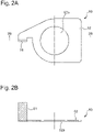
Fig. 2A] Fig. 2A shows a plan view of a rotary baffle plate shown inFig. 1 . - [
Fig. 2B] Fig. 2B shows a cross-sectional view of the rotary baffle plate incross section 2B-2B shown inFig. 2A . - [
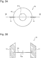
Fig. 3A] Fig. 3A shows a plan view of another example of the rotary baffle plate. - [
Fig. 3B] Fig. 3B shows a cross-sectional view of the rotary baffle plate incross section 3B-3B shown inFig. 3A . - [
Fig. 4A] Fig. 4A shows a plan view of still another example of the rotary baffle plate. - [
Fig. 4B] Fig. 4B shows a cross-sectional view of the rotary baffle plate incross section 4B-4B shown inFig. 4A . - [
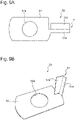
Fig. 5A] Fig. 5A shows a plan view of a further example of the rotary baffle plate. - [
Fig. 5B] Fig. 5B shows a cross-sectional view of the rotary baffle plate incross section 5B-5B shown inFig. 5A . - [
Fig. 6A] Fig. 6A shows a plan view of a further example of the rotary baffle plate. - [
Fig. 6B] Fig. 6B shows a side view seen fromarrow 6B-6B shown inFig. 6A . - [
Fig. 6C] Fig. 6C shows a side view seen fromarrow 6C-6C shown inFig. 6A . - [
Fig. 7A] Fig. 7A shows a plan view of a further example of the rotary baffle plate. - [
Fig. 7B] Fig. 7B shows a side view seen fromarrow 7B-7B shown inFig. 7A . - [
Fig. 7C] Fig. 7C shows a side view seen fromarrow 7C-7C shown inFig. 7A . - [
Fig. 8A] Fig. 8A shows a plan view of a further example of the rotary baffle plate. - [
Fig. 8B] Fig. 8B shows a side view seen fromarrow 8B-8B shown inFig. 8A . - [
Fig. 8C] Fig. 8C shows a side view seen fromarrow 8C-8C shown inFig. 8A . - [
Fig. 9A] Fig. 9A shows a plan view of a material of a still further example of the rotary baffle plate. - [
Fig. 9B] Fig. 9B shows a perspective view of the rotary baffle plate formed of the material shown inFig. 9A . - [
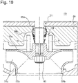
Fig. 10] Fig. 10 is an enlarged cross-sectional view of a pump according to another embodiment. - [
Fig. 11] Fig. 11 is an enlarged cross-sectional view of a pump according to still another embodiment. - [
Fig. 12A] Fig. 12A shows a plan view of a material of another example of the rotary baffle plate. - [
Fig. 12B] Fig. 12B shows a perspective view of the rotary baffle plate formed of the material shown inFig. 12A . - [
Fig. 13A] Fig. 13A shows a perspective view of still another example of the rotary baffle plate. - [
Fig. 13B] Fig. 13B shows a side view of the rotary baffle plate shown inFig. 13A . - [
Fig. 14] Fig. 14 shows a side view of a further example of the rotary baffle plate. - [
Fig. 15] Fig. 15 shows a side view of a still further example of the rotary baffle plate. - Hereinafter, embodiments of the present invention will be described with reference to the drawings. In the drawings described below, the same or corresponding constituent elements are denoted with the same reference sign and are not redundantly described. In the embodiments described below, a vertical centrifugal pump is described as an example of a pump of the present invention, but is not limited, and any pump to which the present invention is applicable may be included in the present invention.
-
Fig. 1 is a partial side cross-sectional view of a pump according to the present embodiment.Fig. 1 shows amotor 20 only in a side view and other parts in a cross-sectional view. As shown, apump 10 includes themotor 20, arotary shaft 31, animpeller 33, and acasing 35. Themotor 20 comprises amotor spindle 21 extending in a vertical direction and is fixed to amotor base 22 fixed to thecasing 35. - An end of the
motor spindle 21 and one end of therotary shaft 31 are coupled by acoupling part 32. Thus, power of themotor 20 is transmitted to therotary shaft 31 via themotor spindle 21 and thecoupling part 32, and therotary shaft 31 rotates in a circumferential direction. Theimpeller 33 is fixed at the other end of therotary shaft 31. Specifically, as shown inFIG. 1 , therotary shaft 31 includes alarge diameter portion 31a and asmall diameter portion 31b located on a tip side of thelarge diameter portion 31a. Thesmall diameter portion 31b of therotary shaft 31 engages with theimpeller 33 via a key. With thesmall diameter portion 31b of therotary shaft 31 inserted into theimpeller 33, theimpeller 33 is fixed to therotary shaft 31 by abolt 42. Theimpeller 33 includes amain plate 33a located on amotor 20 side (mechanical seal 38 side described later), aside plate 33b and a plurality ofwings 33c provided between themain plate 33a and theside plate 33b. - The
casing 35 includes anupper casing 36 and alower casing 37. Theupper casing 36 has anopening 36a into which therotary shaft 31 is inserted. Thepump 10 includes, between theopening 36a of theupper casing 36 and therotary shaft 31, the mechanical seal 38 (corresponding to an example of a shaft sealing device) that seals a gap between theupper casing 36 and therotary shaft 31. Theupper casing 36 includes amechanical chamber 36b for storing themechanical seal 38. - The
lower casing 37 is configured to house theimpeller 33 and a part of therotary shaft 31 inside. Further, thelower casing 37 includes asuction port 37a through which liquid is introduced into thelower casing 37 and adischarge port 37b through which the liquid introduced into thelower casing 37 is discharged. - In the
pump 10 having the shown configuration, therotary shaft 31 is rotated by torque given from themotor 20, and theimpeller 33 rotates with therotary shaft 31. The liquid is introduced into thepump 10 through thesuction port 37a of thelower casing 37, boosted by the rotatingimpeller 33, and then discharged through thedischarge port 37b to outside of thepump 10. - As described above, when the
pump 10 is primed with water before being operated, an interior of thecasing 35 of thepump 10 cannot be filled with water, and air is accumulated inside themechanical chamber 36b, that is, around themechanical seal 38. When thepump 10 is operated in this state, water present on a back side of themain plate 33a of theimpeller 33 moves in the circumferential direction with the rotation of theimpeller 33. - Pumps of recent years may have a rotation speed controlled by an inverter. When the
impeller 33 rotates at a relatively high rotation speed (e.g., 3000 rpm), the water on the back side of themain plate 33a also moves in the circumferential direction at a relatively high speed. Therefore, with this movement of water, air in themechanical chamber 36b also moves in the circumferential direction, and the air in themechanical chamber 36b may be discharged with water. However, when thepump 10 is operated at a relatively low rotation speed (e.g., 450 rpm), the water on the back side of themain plate 33a does not move in the circumferential direction for discharging air in themechanical chamber 36b, and the air in themechanical chamber 36b cannot be discharged. - Therefore, the
pump 10 of the present embodiment includes arotary baffle plate 50 located between theimpeller 33 and themechanical seal 38 and attached to a rotating body of thepump 10.Fig. 2A shows a plan view of therotary baffle plate 50 shown inFig. 1 .Fig. 2B shows a cross-sectional view of therotary baffle plate 50 incross section 2B-2B shown inFig. 2A . As shown inFigs. 2A and 2B , therotary baffle plate 50 includes abaffle plate part 51 and amain body part 52. As shown inFig. 1 , themain body part 52 of therotary baffle plate 50 is attached to therotary shaft 31 and rotates with therotary shaft 31. In the illustrated embodiment, thebaffle plate part 51 is provided on themain body part 52 and located between theimpeller 33 and themechanical seal 38. More specifically, thebaffle plate part 51 is provided on themain body part 52 to extend from themain body part 52 toward themechanical seal 38 side. Further, thebaffle plate part 51 is disposed inside themechanical chamber 36b. - In the illustrated example, the
main body part 52 is a substantially plate-shaped body. However, this shape is not limited, and any shape such as a cylindrical shape can be adopted if thebaffle plate part 51 can be attached. Therotary baffle plate 50 can be manufactured by perpendicularly bending a part of a single metal plate of, for example, SUS or the like. Alternatively, therotary baffle plate 50 may be manufactured by welding thebaffle plate part 51 to themain body part 52. - As shown in
Fig. 1 , thebaffle plate part 51 extends in a direction that is inclined or orthogonal with respect to a surface orthogonal to an axial direction of therotary shaft 31. In other words, thebaffle plate part 51 extends from themain body part 52 to have an angle with respect to the plate-shapedmain body part 52. Preferably, as shown inFig. 1 , thebaffle plate part 51 extends in the direction orthogonal to the surface orthogonal to the axial direction of therotary shaft 31, that is, in parallel with the axial direction of therotary shaft 31. More preferably, as shown inFigs. 1 ,2A and 2B , thebaffle plate part 51 is oriented so that a main surface of thebaffle plate part 51 is parallel to the axial direction of therotary shaft 31 and so that a central axis of therotary shaft 31 is included in the same plane as the main surface of thebaffle plate part 51. Thebaffle plate part 51 can have a length, width, shape, and the like arbitrarily adjusted depending on a shape of themechanical chamber 36b. In principle, the larger an area of thebaffle plate part 51 is, the more an effect of discharging air from themechanical chamber 36b can improve. In the present description, "the main surface of thebaffle plate part 51" refers to a surface that receives the most resistance from water when thebaffle plate part 51 rotates with therotary shaft 31. - As shown in
Fig. 2A , themain body part 52 has anopening 52a through which thesmall diameter portion 31b of therotary shaft 31 passes. As shown inFig. 1 , themain body part 52 is sandwiched between thelarge diameter portion 31a of therotary shaft 31 and theimpeller 33. Thus, themain body part 52 frictionally engages with thelarge diameter portion 31a and theimpeller 33, and therotary baffle plate 50 can rotate with the rotation of therotary shaft 31. In this case, themain body part 52 can be attached to therotary shaft 31 without requiring any special parts, structures or the like. Not limited to this, therotary baffle plate 50 can be fixed to therotary shaft 31 by any engaging method, for example, key engagement or the like. - Further, it is preferable that the
rotary baffle plate 50 has a center of gravity that is present on the central axis of therotary shaft 31. This can suppress occurrence of vibration on therotary shaft 31 when therotary baffle plate 50 rotates with therotary shaft 31. - As described above, the
pump 10 of the present embodiment includes thebaffle plate part 51 located between theimpeller 33 and themechanical seal 38 and attached to the rotating body (main body part 52). Thus, thebaffle plate part 51 rotates with therotary shaft 31 and can mix water and air between theimpeller 33 and themechanical seal 38, that is, around themechanical seal 38 and efficiently discharge air with water from thepump 10. Further, since thepump 10 includes thebaffle plate part 51, it is possible to easily mix water and air around themechanical seal 38 and to discharge air from thepump 10, even when thepump 10 is operated at the relatively low rotation speed. When thepump 10 is operated at a normal rotation speed or the relatively high rotation speed, air can be discharged from thepump 10 more efficiently. - Further, in the
pump 10 of the present embodiment, it is not necessary to process thecasing 35 or theimpeller 33, for example, by making a hole. Therefore, a decrease in pump efficiency due to this processing can be prevented, and cost required for the processing can be unnecessary. - Also, in the
pump 10 of the present embodiment, thebaffle plate part 51 is provided on themain body part 52 to extend from themain body part 52 toward themechanical seal 38 side. Thereby, thebaffle plate part 51 can mix water and air around themechanical seal 38, and efficiently discharge air with water from thepump 10. - Next, other examples of the
rotary baffle plate 50 will be described.Fig. 3A shows a plan view of another example of therotary baffle plate 50.Fig. 3B shows a cross-sectional view of therotary baffle plate 50 incross section 3B-3B shown inFig. 3A . In therotary baffle plate 50 shown inFig. 3A , themain body part 52 has a doughnut-shaped disc shape. Therotary baffle plate 50 also includes twobaffle plate parts 51. As shown inFigs. 2A and 2B , thebaffle plate part 51 extends above and below themain body part 52 in parallel with the axial direction of therotary shaft 31 and is oriented so that the central axis of therotary shaft 31 is included in the same plane as the main surface of thebaffle plate part 51. Thebaffle plate part 51 can be joined to themain body part 52, for example, by welding. Thus, therotary baffle plate 50 according to the present embodiment may comprise a plurality ofbaffle plate parts 51. -
Fig. 4A shows a plan view of another example of therotary baffle plate 50.Fig. 4B shows a cross-sectional view of therotary baffle plate 50 incross section 4B-4B shown inFig. 4A . Therotary baffle plate 50 shown inFig. 4A includes a plate-shapedmain body part 52 in the same manner as therotary baffle plate 50 shown inFigs. 2A and 2B andFigs. 3A and 3B . Further, therotary baffle plate 50 includes two identically shapedbaffle plate parts 51. As shown inFig. 4B , onebaffle plate part 51 is configured to extend in one way of (e.g., above) themain body part 52, and the otherbaffle plate part 51 is configured to extend in another way (e.g., below). Bothbaffle plate parts 51 extend in parallel with the axial direction of therotary shaft 31 and are oriented so that the central axis of therotary shaft 31 is included in the same plane as the main surface of thebaffle plate part 51. Therotary baffle plate 50 can be manufactured by perpendicularly bending a part of a single metal plate of, for example, SUS or the like. Alternatively, therotary baffle plate 50 may be manufactured by welding thebaffle plate parts 51 to themain body part 52. Thus, therotary baffle plate 50 may be configured so that a plurality ofbaffle plate parts 51 having the same shape extend in respective opposite directions. Thereby, orientation in which therotary baffle plate 50 is attached to therotary shaft 31 is not limited, and hence human error when attaching therotary baffle plate 50 to therotary shaft 31 can be prevented. -
Fig. 5A shows a plan view of another example of therotary baffle plate 50.Fig. 5B shows a cross-sectional view of therotary baffle plate 50 incross section 5B-5B shown inFig. 5A . Therotary baffle plate 50 shown inFig. 5A includes a plate-shapedmain body part 52 in the same manner as therotary baffle plate 50 shown inFigs. 4A and 4B . Further, thisrotary baffle plate 50 includes twobaffle plate parts 51 having different shapes. As shown inFig. 5B , onebaffle plate part 51 is configured to extend in one way of (e.g., above) themain body part 52, and the otherbaffle plate part 51 is configured to extend in another way (e.g., below). Bothbaffle plate parts 51 extend in parallel with the axial direction of therotary shaft 31 and are oriented so that the central axis of therotary shaft 31 is included in the same plane as the main surface of thebaffle plate part 51. Therotary baffle plate 50 can be manufactured by perpendicularly bending a part of a single metal plate of, for example, SUS or the like. Alternatively, therotary baffle plate 50 may be manufactured by welding thebaffle plate parts 51 to themain body part 52. Thus, therotary baffle plate 50 may be configured so that a plurality ofbaffle plate parts 51 having different shapes extend in respective opposite directions. Thereby, orientation in which therotary baffle plate 50 is attached to therotary shaft 31 is not limited, and hence human error when attaching therotary baffle plate 50 to therotary shaft 31 can be prevented. -
Fig. 6A shows a plan view of another example of therotary baffle plate 50.Fig. 6B shows a side view seen fromarrow 6B-6B shown inFig. 6A. Fig. 6C shows a side view seen fromarrow 6C-6C shown inFig. 6A. Figs 6B and 6C show therotary shaft 31 for the convenience of explanation. Therotary baffle plate 50 shown inFigs. 6A to 6C includes amain body part 52 having a doughnut-shaped disc shape in the same manner as in therotary baffle plate 50 shown inFigs. 3A and 3B . Further, therotary baffle plate 50 includes a pair ofbaffle plate parts 51 extending in a direction that is inclined with respect to a surface orthogonal to the axial direction of therotary shaft 31. Specifically, in the illustrated example, the pair ofbaffle plate parts 51 extend upward from the main body part 52 (on amechanical seal 38 side) to be inclined at the same angle in directions opposite to each other. The pair ofbaffle plate parts 51 may extend to be inclined in the same direction or to be inclined at angles different from each other. Therotary baffle plate 50 may be manufactured by welding thebaffle plate parts 51 to themain body part 52. Thus, in therotary baffle plate 50, thebaffle plate parts 51 may extend to be inclined with respect to the surface orthogonal to the axial direction of therotary shaft 31. -
Fig. 7A shows a plan view of another example of therotary baffle plate 50.Fig. 7B shows a side view seen fromarrow 7B-7B shown inFig. 7A. Fig. 7C shows a side view seen fromarrow 7C-7C shown inFig. 7A. Figs. 7B and 7C show therotary shaft 31 for the convenience of explanation. Therotary baffle plate 50 shown inFigs. 7A to 7C includes amain body part 52 having a doughnut-shaped disc shape in the same manner as therotary baffle plate 50 shown inFigs. 3A and 3B . Further, therotary baffle plate 50 includes a pair ofbaffle plate parts 51 extending in a direction orthogonal to a surface orthogonal to the axial direction of therotary shaft 31, that is, in parallel with therotary shaft 31. In the illustrated example, the pair ofbaffle plate parts 51 have a main surface parallel to the axial direction of therotary shaft 31, but thebaffle plate parts 51 are oriented so that the central axis of therotary shaft 31 is not included in the same plane as the main surface. In the illustrated example, the main surfaces of the pair ofbaffle plate parts 51 are parallel to each other but are not limited. Therotary baffle plate 50 may be manufactured by welding thebaffle plate parts 51 to themain body part 52. Thus, therotary baffle plate 50 may be configured so that the central axis of therotary shaft 31 is not included in the same plane as the main surface of thebaffle plate part 51. -
Fig. 8A shows a plan view of another example of therotary baffle plate 50.Fig. 8B shows a side view seen fromarrow 8B-8B shown inFig. 8A. Fig. 8C shows a side view seen fromarrow 8C-8C shown inFig. 8A. Figs. 8B and 8C show therotary shaft 31 for the convenience of explanation. Therotary baffle plate 50 shown inFigs. 8A to 8C includes amain body part 52 having a doughnut-shaped disc shape in the same manner as therotary baffle plate 50 shown inFigs. 3A and 3B . Further, therotary baffle plate 50 includes a pair ofbaffle plate parts 51 extending in a direction orthogonal to a surface orthogonal to the axial direction of therotary shaft 31, that is, in parallel with therotary shaft 31. In the illustrated example, a pair ofbaffle plate parts 51 have a larger thickness than thebaffle plate part 51 shown inFigs. 2 to 7 . Eachbaffle plate part 51 in the illustrated example has a main surface that is a side surface of thebaffle plate part 51 seen from a direction shown inFig. 8B . Therefore, in the illustrated example, the main surface of thebaffle plate part 51 extends in parallel with the axial direction of therotary shaft 31. On the other hand, thebaffle plate part 51 is oriented so that the central axis of therotary shaft 31 is not included in the same plane as the main surface of the baffle plate part. Thus, "thebaffle plate part 51" in the present description includes not only a thin plate-shaped body but also a columnar body. -
Fig. 9A shows a plan view of a material of another example of therotary baffle plate 50.Fig. 9B shows a perspective view of therotary baffle plate 50 formed of the material shown inFig. 9A . As shown inFig. 9A , the material of therotary baffle plate 50 is a single metal plate of, for example, SUS or the like, and includes amain body part 52 and abaffle plate part 51. Thebaffle plate part 51 includes amain surface portion 51b that receives the most resistance from water when thebaffle plate part 51 rotates with therotary shaft 31, and acoupling portion 51a coupling themain surface portion 51b and themain body part 52. - The
rotary baffle plate 50 shown inFig. 9B is formed by bending thecoupling portion 51a of the material shown inFig. 9A at right angles to themain body part 52 and bending themain surface portion 51b at right angles to thecoupling portion 51a. In therotary baffle plate 50 shown inFig. 9B , thebaffle plate part 51 is oriented so that a main surface of themain surface portion 51b of thebaffle plate part 51 is parallel to the axial direction of therotary shaft 31 and the central axis of therotary shaft 31 is included in the same plane as the main surface. Thus, since therotary baffle plate 50 can be formed by bending the plate material twice, processing such as welding is unnecessary, and production cost can be reduced though increasing strength. - Next, a
pump 10 according to another embodiment will be described.Fig. 10 is an enlarged cross-sectional view of thepump 10 according to the embodiment.Fig. 10 shows the vicinity of animpeller 33 and amechanical seal 38 in an enlarged manner. A part that is not shown inFig. 10 may have a structure like thepump 10 shown inFig. 1 . Thepump 10 shown inFig. 10 does not include arotary baffle plate 50 compared to thepump 10 shown inFig. 1 . Instead, thepump 10 shown inFig. 10 includes abaffle plate part 51 attached to amain plate 33a of theimpeller 33. - The
baffle plate part 51 shown inFig. 10 is located between theimpeller 33 and themechanical seal 38 and is attached to theimpeller 33 that is a rotating body, for example, by welding or the like. As shown inFig. 10 , thebaffle plate part 51 extends in a direction that is inclined or orthogonal with respect to a surface orthogonal to an axial direction of arotary shaft 31. Preferably, as shown inFig. 10 , thebaffle plate part 51 extends in a direction orthogonal to a surface orthogonal to the axial direction of therotary shaft 31, that is, in parallel with the axial direction of therotary shaft 31. More preferably, as shown inFig. 10 , the baffle plate part is oriented so that a main surface of thebaffle plate part 51 is parallel to the axial direction of therotary shaft 31 and so that a central axis of therotary shaft 31 is included in the same plane as the main surface of thebaffle plate part 51. Thereby, thebaffle plate part 51 can efficiently stir water. - According to the
pump 10 shown inFig. 10 , thebaffle plate part 51 rotates with therotary shaft 31 and can mix water and air inside amechanical chamber 36b, that is, around themechanical seal 38, and efficiently discharge air with water from thepump 10. Further, since thepump 10 includes thebaffle plate part 51, it is possible to easily mix water and air around themechanical seal 38, and to discharge air from thepump 10, even when thepump 10 is operated at a relatively low rotation speed. When thepump 10 is operated at a normal rotation speed or a relatively high rotation speed, air can be discharged from thepump 10 more efficiently. - Further, in the
pump 10 of the present embodiment, although processing of attaching thebaffle plate part 51 to the existingimpeller 33 is required, there is an advantage that another part such as therotary baffle plate 50 does not need to be prepared separately. -
Fig. 11 is an enlarged cross-sectional view of apump 10 according to another embodiment.Fig. 11 shows the vicinity of animpeller 33 and amechanical seal 38 in an enlarged manner. A part that is not shown inFig. 11 may have a structure like thepump 10 shown inFig. 1 . Thepump 10 shown inFig. 11 does not include arotary baffle plate 50 compared to thepump 10 shown inFig. 1 . Instead, thepump 10 shown inFig. 11 includes abaffle plate part 51 attached to themechanical seal 38. - The
mechanical seal 38 includes a fixed ring 38a fixed to anupper casing 36 and a rotating ring 38b rotating with arotary shaft 31. Abaffle plate part 51 shown inFig. 11 is located between theimpeller 33 and themechanical seal 38 and is attached to the rotating ring 38b that is a rotating body, for example, by welding or the like. As shown inFig. 11 , thebaffle plate part 51 extends in a direction that is inclined or orthogonal with respect to a surface orthogonal to an axis direction of therotary shaft 31. Preferably, as shown inFig. 11 , thebaffle plate part 51 extends in a direction orthogonal to the surface orthogonal to the axial direction of therotary shaft 31, that is, in parallel with the axial direction of therotary shaft 31. More preferably, as shown inFig. 11 , thebaffle plate part 51 is oriented so that a main surface of thebaffle plate part 51 is parallel to the axial direction of therotary shaft 31 and so that a central axis of therotary shaft 31 is included in the same plane as the main surface of thebaffle plate part 51. - According to the
pump 10 shown inFig. 11 , thebaffle plate part 51 rotates with therotary shaft 31 and can mix water and air inside amechanical chamber 36b, that is, around themechanical seal 38, and efficiently discharge air with water from thepump 10. Further, since thepump 10 includes thebaffle plate part 51, it is possible to easily mix water and air around themechanical seal 38, and to discharge air from thepump 10, even when thepump 10 is operated at a relatively low rotation speed. When thepump 10 is operated at a normal rotation speed or a relatively high rotation speed, air can be discharged from thepump 10 more efficiently. - Further, in the
pump 10 of the present embodiment, although processing of attaching thebaffle plate part 51 to the existingmechanical seal 38 is required, there is an advantage that another part such as therotary baffle plate 50 does not need to be prepared separately. -
Fig. 12A shows a plan view of a material of another example of therotary baffle plate 50.Fig. 12B shows a perspective view of therotary baffle plate 50 formed of the material shown inFig. 12A . As shown inFig. 12A , the material of therotary baffle plate 50 is a single metal plate of, for example, SUS or the like, and includes amain body part 52 and abaffle plate part 51. Thebaffle plate part 51 includes an upperbaffle plate portion 51c and a lowerbaffle plate portion 51d. In the illustrated example, the baffle plate part includes two upperbaffle plate portions 51c and two lowerbaffle plate portions 51d, but is not limited, and thebaffle plate part 51 may include at least one upperbaffle plate portion 51c and at least one lowerbaffle plate portion 51d. - As shown in
Figs. 12A and 12B , each lowerbaffle plate portion 51d is a substantially rectangular plate-shaped body shorter than the upperbaffle plate portion 51c. The upperbaffle plate portion 51c has a shape in which one corner of the rectangular plate-shaped body is chamfered. Specifically, in the upperbaffle plate portion 51c, a corner on a side away from anopening 52a, through which arotary shaft 31 passes, is chamfered in an arc shape with a width gradually decreasing toward a tip. That is, the upperbaffle plate portion 51c may have an arc-shapedtip surface 55 in a plane shown inFig. 12A . As shown inFig. 12B , the upperbaffle plate portion 51c extends upward in parallel with an axial direction of therotary shaft 31 when therotary baffle plate 50 is attached to therotary shaft 31. The lowerbaffle plate portion 51d extends downward in parallel with the axial direction of therotary shaft 31 when therotary baffle plate 50 is attached to therotary shaft 31. - The
rotary baffle plate 50 also includes a fixingpart 54. The fixingpart 54 may be a plate-shaped body extending substantially at right angles to themain body part 52. The fixingpart 54 is located adjacent to theopening 52a and engages in a keyway of animpeller 33 and/or a keyhole of therotary shaft 31 so that themain body part 52 does not move in a circumferential direction with respect to therotary shaft 31 or theimpeller 33 when therotary baffle plate 50 is attached to therotary shaft 31. Since therotary baffle plate 50 includes the fixingpart 54, therotary baffle plate 50 can be securely fixed so as not to move in the circumferential direction with respect to therotary shaft 31 or theimpeller 33. - In order to form the
rotary baffle plate 50 shown inFig. 12B , the upperbaffle plate portions 51c, the lowerbaffle plate portions 51d and the fixingpart 54 shown inFig. 12 are bent substantially at right angles to themain body part 52. Specifically, the upperbaffle plate portions 51c are bent substantially at right angles to themain body part 52, and the lowerbaffle plate portions 51d and the fixingpart 54 are bent substantially at right angles in a direction opposite to a bending direction of the upperbaffle plate portions 51c. - Further, as shown in
Figs. 12A and 12B , when thebaffle plate part 51 is bent and formed, themain body part 52 preferably includes acurved relief portion 53 near a base of thebaffle plate part 51. Thecurved relief portion 53 may be a cutout formed in themain body part 52. Themain body part 52 includes thecurved relief portion 53, and hence even if thebaffle plate part 51 is bent at right angles to themain body part 52, stress is inhibited from being concentrated on the base of thebaffle plate part 51 during operation of thepump 10. As a result, thebaffle plate part 51 can be prevented from being broken early. Further, in the illustrated example, since the fixingpart 54 is also bent and formed, it is preferable that themain body part 52 includes thecurved relief portion 53 near the base of the fixingpart 54. -
Fig. 13A is a perspective view of another example of therotary baffle plate 50.Fig. 13B is a side view of therotary baffle plate 50 shown inFig. 13A . Therotary baffle plate 50 shown inFigs. 13A and 13B is different from therotary baffle plate 50 shown inFigs. 12A and 12B only in that a lowerbaffle plate portion 51d is not provided. Thus, the lowerbaffle plate portion 51d may be omitted from therotary baffle plate 50 shown inFigs. 12A and 12B . -
Fig. 14 shows a side view of another example of therotary baffle plate 50. Therotary baffle plate 50 shown inFig. 14 is different from therotary baffle plate 50 shown inFigs. 12A and 12B only in a shape of atip surface 55 of an upperbaffle plate portion 51c. The upperbaffle plate portion 51c of therotary baffle plate 50 shown inFig. 14 has a shape in which one corner of a rectangular plate-shaped body is chamfered in a square surface shape. Specifically, in the upperbaffle plate portion 51c, the corner away from anopening 52a, through which arotary shaft 31 passes, is chamfered in the square surface shape with a width gradually decreasing toward a tip. That is, inFig. 14 , the upperbaffle plate portion 51c includes thelinear tip surface 55 inclined with respect to a main surface of amain body part 52. -
Fig. 15 shows a side view of another example of therotary baffle plate 50. Therotary baffle plate 50 shown inFig. 15 is different from therotary baffle plate 50 shown inFigs. 12A and 12B only in a shape of atip surface 55 of an upperbaffle plate portion 51c. The upperbaffle plate portion 51c of therotary baffle plate 50 shown inFig. 15 has a shape in which one corner of a rectangular plate-shaped body is chamfered twice in a square surface shape. Specifically, in the upperbaffle plate portion 51c, the corner away from anopening 52a, through which arotary shaft 31 passes, is chamfered twice in the square surface shape with a width gradually decreasing toward a tip. That is, inFig. 14 , the upperbaffle plate portion 51c includes a linearfirst tip surface 55a inclined with respect to a main surface of amain body part 52, and a linearsecond tip surface 55b inclined at an angle different from that of thefirst tip surface 55a. - The embodiments of the present invention have been described above, but the above embodiments of the present invention are described to facilitate understanding of the present invention and are not intended to limit the present invention. The present invention may be changed or modified without departing from the spirit, and the present invention includes equivalents to the embodiment. Also, in a range in which at least some of the above-described problems can be solved or a range in which at least some of effects are exhibited, any combination or omission of respective constituent components described in claims and description is possible.
- The present description discloses aspects as follows.
- In a first aspect, a pump is provided. This pump includes a rotary shaft, an impeller that is attached to the rotary shaft and that rotates with rotation of the rotary shaft, a casing that surrounds the rotary shaft, a shaft sealing device that seals a gap between the casing and the rotary shaft, and a baffle plate part that is located between the impeller and the shaft sealing device and attached to a rotating body, the baffle plate part extending in a direction that is inclined or orthogonal with respect to a surface orthogonal to an axial direction of the rotary shaft.
- According to the first aspect, the baffle plate part rotates with the rotating body, and can therefore mix water and air between the impeller and the shaft sealing device and efficiently discharge air with water from the pump. Therefore, since it is not necessary to process the casing or the impeller, for example, by making a hole or the like, a decrease in pump efficiency due to this processing can be prevented, and cost required for the processing can be unnecessary. Also, since the pump includes the baffle plate part, it is possible to easily mix water and air between the impeller and the shaft sealing device and to discharge air from the pump, even when the pump is operated at a relatively low rotation speed. In addition, when the pump is operated at a normal rotation speed or a relatively high rotation speed, air can be discharged from the pump more efficiently.
- A second aspect provides that the pump of the first aspect further includes a rotary baffle plate that is attached to the rotary shaft so as to be located between the impeller and the shaft sealing device, the rotary baffle plate including a main body part attached to the rotary shaft, and the baffle plate part provided on the main body part.
- According to the second aspect, air in the pump can be discharged only by attaching the main body part provided with the baffle plate part to the rotary shaft.
- A third aspect provides that in the pump of the second aspect, the rotary baffle plate has a center of gravity that is present on a central axis of the rotary shaft.
- The third aspect can suppress occurrence of vibration on the rotary shaft when the baffle plate part and main body part rotate with the rotary shaft.
- A fourth aspect provides that in the pump of the second or third aspect, the baffle plate part extends from the main body part to a side of the shaft sealing device.
- According to the fourth aspect, the baffle plate part can mix water and air around the shaft sealing device and efficiently discharge air with water from the pump.
- A fifth aspect provides that in the pump of any of the second to fourth aspects, the rotary shaft includes a large diameter portion, and a small diameter portion located on a tip side of the large diameter portion, and the main body part has an opening through which the small diameter portion of the rotary shaft passes, and is sandwiched between the large diameter portion of the rotary shaft and the impeller and attached to the rotary shaft.
- According to the fifth aspect, the main body part can be attached to the rotary shaft without requiring any special parts, structures or the like.
- A sixth aspect provides that in the pump of any of the second to fifth aspects, the main body part includes a fixing part that engages with the rotary shaft or the impeller so that the main body part does not move in a circumferential direction with respect to the rotary shaft or the impeller.
- According to the sixth aspect, the fixing part allows the rotary baffle plate to be securely fixed so that the rotary baffle plate does not move in the circumferential direction with respect to the rotary shaft or the impeller.
- A seventh aspect provides that in the pump of any of the second to sixth aspects, the main body part includes a curved relief portion near a base of the baffle plate part.
- According to the seventh aspect, even if the baffle plate part is bent at right angles to the main body part, stress is inhibited from being concentrated on the base of the baffle plate part during operation of the pump. As a result, the baffle plate part can be prevented from being broken early.
- An eighth aspect provides that in the pump of the first aspect, the impeller includes a main plate, and the baffle plate part is attached to the main plate of the impeller.
- According to the eighth aspect, another part such as a rotary baffle plate does not need to be prepared separately, and the baffle plate part can mix water and air and efficiently discharge air with water from the
pump 10. - A ninth aspect provides that in the pump of the first aspect, the shaft sealing device is a mechanical seal including a fixed ring and a rotating ring, and the baffle plate part is attached to the rotating ring of the mechanical seal.
- According to the ninth aspect, another part such as the rotary baffle plate does not need to be prepared separately, and the baffle plate part can mix water and air and efficiently discharge air with water from the pump.
- A tenth aspect provides that in the pump of any of the first to ninth aspects, the baffle plate part is oriented so that a main surface of the baffle plate part is parallel to an axial direction of the rotary shaft and a central axis of the rotary shaft is included in the same plane as the main surface.
- According to the tenth aspect, the baffle plate part can efficiently stir water.
- In an eleventh aspect, a rotary baffle plate that is attached to a rotary shaft so as to be located between an impeller and a shaft sealing device in a pump is provided. This rotary baffle plate includes a main body part including an opening into which the rotary shaft is inserted, and attached to the rotary shaft, and a baffle plate part attached to the main body part and extending in a direction that is inclined or orthogonal with respect to a surface orthogonal to an axial direction of the rotary shaft in a state where the main body part is attached to the rotary shaft.
- According to the eleventh aspect, since the rotary baffle plate is attached to the rotary shaft, the baffle plate part rotates with the rotary shaft, and can therefore mix water and air between the impeller and the shaft sealing device and efficiently discharge air with water from the pump. Therefore, it is not necessary to process the casing or the impeller, for example, by making a hole, so that a decrease in pump efficiency due to this processing can be prevented, and cost required for the processing can be unnecessary.
-
- 10
- pump
- 31
- rotary shaft
- 31a
- large diameter portion
- 31b
- small diameter portion
- 33
- impeller
- 33a
- main plate
- 35
- casing
- 36
- upper casing
- 37
- lower casing
- 38
- mechanical seal
- 38a
- fixed ring
- 38b
- rotating ring
- 50
- rotary baffle plate
- 51
- baffle plate part
- 52
- main body part
- 52a
- opening
- 53
- curved relief portion
- 54
- fixing part
Claims (11)
- A pump comprising:a rotary shaft,an impeller that is attached to the rotary shaft and that rotates with rotation of the rotary shaft,a casing that surrounds the rotary shaft,a shaft sealing device that seals a gap between the casing and the rotary shaft, anda baffle plate part that is located between the impeller and the shaft sealing device and attached to a rotating body,the baffle plate part extending in a direction that is inclined or orthogonal with respect to a surface orthogonal to an axial direction of the rotary shaft.
- The pump according to claim 1, further comprising:a rotary baffle plate that is attached to the rotary shaft so as to be located between the impeller and the shaft sealing device,the rotary baffle plate including a main body part attached to the rotary shaft, and the baffle plate part provided on the main body part.
- The pump according to claim 2, wherein the rotary baffle plate has a center of gravity that is present on a central axis of the rotary shaft.
- The pump according to claim 2 or 3, wherein the baffle plate part extends from the main body part to a side of the shaft sealing device.
- The pump according to any one of claims 2 to 4, wherein the rotary shaft includes a large diameter portion, and a small diameter portion located on a tip side of the large diameter portion, and
the main body part has an opening through which the small diameter portion of the rotary shaft passes, and is sandwiched between the large diameter portion of the rotary shaft and the impeller and attached to the rotary shaft. - The pump according to any one of claims 2 to 5, wherein the main body part includes a fixing part that engages with the rotary shaft or the impeller so that the main body part does not move in a circumferential direction with respect to the rotary shaft or the impeller.
- The pump according to any one of claims 2 to 6, wherein the main body part includes a curved relief portion near a base of the baffle plate part.
- The pump according to claim 1, wherein the impeller includes a main plate, and
the baffle plate part is attached to the main plate of the impeller. - The pump according to claim 1, wherein the shaft sealing device is a mechanical seal including a fixed ring and a rotating ring, and
the baffle plate part is attached to the rotating ring of the mechanical seal. - The pump according to any one of claims 1 to 9, wherein the baffle plate part is oriented so that a main surface of the baffle plate part is parallel to an axial direction of the rotary shaft and a central axis of the rotary shaft is included in the same plane as the main surface.
- A rotary baffle plate that is attached to a rotary shaft so as to be located between an impeller and a shaft sealing device in a pump, the rotary baffle plate comprising:a main body part including an opening into which the rotary shaft is inserted, and attached to the rotary shaft, anda baffle plate part attached to the main body part and extending in a direction that is inclined or orthogonal with respect to a surface orthogonal to an axial direction of the rotary shaft in a state where the main body part is attached to the rotary shaft.
Applications Claiming Priority (2)
| Application Number | Priority Date | Filing Date | Title |
|---|---|---|---|
| JP2019226550 | 2019-12-16 | ||
| PCT/JP2020/046853 WO2021125197A1 (en) | 2019-12-16 | 2020-12-16 | Pump and rotary baffle plate |
Publications (2)
| Publication Number | Publication Date |
|---|---|
| EP4080059A1 true EP4080059A1 (en) | 2022-10-26 |
| EP4080059A4 EP4080059A4 (en) | 2024-01-10 |
Family
ID=76478812
Family Applications (1)
| Application Number | Title | Priority Date | Filing Date |
|---|---|---|---|
| EP20902030.4A Pending EP4080059A4 (en) | 2019-12-16 | 2020-12-16 | Pump and rotary baffle plate |
Country Status (4)
| Country | Link |
|---|---|
| US (1) | US11913466B2 (en) |
| EP (1) | EP4080059A4 (en) |
| JP (1) | JP7504917B2 (en) |
| WO (1) | WO2021125197A1 (en) |
Family Cites Families (18)
| Publication number | Priority date | Publication date | Assignee | Title |
|---|---|---|---|---|
| JPS60178391U (en) | 1984-05-04 | 1985-11-27 | 株式会社荏原製作所 | Centrifugal pump shaft seal extraction device |
| JPS61212695A (en) * | 1985-03-19 | 1986-09-20 | Matsushita Electric Ind Co Ltd | Hugal pump device |
| JPS62111994A (en) | 1985-11-08 | 1987-05-22 | M S C:Kk | Production of saponin |
| JPS62111994U (en) | 1986-01-08 | 1987-07-16 | ||
| TW265395B (en) | 1993-03-18 | 1995-12-11 | Warman Int Ltd | |
| JP3386254B2 (en) | 1994-09-30 | 2003-03-17 | 株式会社鶴見製作所 | Submersible pump with cooling water self-circulation device |
| JPH08296587A (en) * | 1995-04-25 | 1996-11-12 | Hitachi Ltd | pump |
| US6036434A (en) * | 1995-10-06 | 2000-03-14 | Roper Holdings, Inc. | Aeration system |
| DE19916803A1 (en) * | 1999-04-14 | 2000-10-19 | Rolls Royce Deutschland | Hydraulic sealing arrangement, in particular on a gas turbine |
| JP2006194201A (en) * | 2005-01-14 | 2006-07-27 | Ebara Corp | Pump |
| JP5063514B2 (en) * | 2008-07-08 | 2012-10-31 | 株式会社鶴見製作所 | Shaft seal device |
| JP5496700B2 (en) * | 2010-02-12 | 2014-05-21 | 株式会社荏原製作所 | Motor pump |
| GB201511456D0 (en) * | 2015-06-30 | 2015-08-12 | Rolls Royce Plc | A seal |
| WO2018053560A1 (en) * | 2016-09-15 | 2018-03-22 | Mechanical Engineering Transcendent Technology (Pty) Ltd | Dry gland stuffing box |
| AU2018390996A1 (en) * | 2017-12-21 | 2020-07-30 | Boyce Barrow | Centrifugal pump assembly and impeller |
| US10865657B2 (en) * | 2018-04-23 | 2020-12-15 | Pratt & Whitney Canada Corp. | Sealing assembly for a gas turbine engine |
| US20200173339A1 (en) * | 2018-12-04 | 2020-06-04 | Gates Corporation | Axial Flux Motor Water Pump |
| US11248492B2 (en) * | 2019-03-18 | 2022-02-15 | Raytheon Technologies Corporation | Seal assembly for a gas turbine engine |
-
2020
- 2020-12-16 EP EP20902030.4A patent/EP4080059A4/en active Pending
- 2020-12-16 WO PCT/JP2020/046853 patent/WO2021125197A1/en not_active Ceased
- 2020-12-16 US US17/757,267 patent/US11913466B2/en active Active
- 2020-12-16 JP JP2021565604A patent/JP7504917B2/en active Active
Also Published As
| Publication number | Publication date |
|---|---|
| US20230003226A1 (en) | 2023-01-05 |
| US11913466B2 (en) | 2024-02-27 |
| WO2021125197A1 (en) | 2021-06-24 |
| JPWO2021125197A1 (en) | 2021-06-24 |
| JP7504917B2 (en) | 2024-06-24 |
| EP4080059A4 (en) | 2024-01-10 |
Similar Documents
| Publication | Publication Date | Title |
|---|---|---|
| KR900001296B1 (en) | Scroll compressor | |
| KR102027695B1 (en) | Scroll compressor | |
| US20120189470A1 (en) | Compressor | |
| EP3677779B1 (en) | Electric oil pump | |
| JP5112741B2 (en) | Vortex pump | |
| JP2008183229A (en) | Turbo blood pump | |
| US20210340979A1 (en) | Roots pump | |
| US11913466B2 (en) | Pump and rotary baffle plate | |
| CN211288078U (en) | scroll compressor | |
| CN221568824U (en) | Spherical rotor pump and tooth cleaning device | |
| WO2018131088A1 (en) | Compressor | |
| CN114776710B (en) | Radial gas bearing device and motor | |
| JP5622473B2 (en) | Scroll compressor | |
| JP2008267168A (en) | Gear pump | |
| CN111502958B (en) | Baffle plate assembly for compressor and compressor with same | |
| JP2002180976A (en) | Scroll compressor | |
| EP1921318A1 (en) | Uniaxial eccentric screw pump | |
| CN213598236U (en) | Wear-resisting ring structure and split pump | |
| EP4080075B1 (en) | Inner coupling for hollow shaft motor | |
| KR100574780B1 (en) | Pumps with mechanical seals without elastic members | |
| KR100695934B1 (en) | Fluid Discharge Structure of Gerotor Pump | |
| JP7159896B2 (en) | underwater pump | |
| JP2009007957A (en) | Centrifugal pump | |
| KR101221263B1 (en) | A Scroll Compressor | |
| JP2011174399A (en) | Rotor fixing structure of fluid machine |
Legal Events
| Date | Code | Title | Description |
|---|---|---|---|
| STAA | Information on the status of an ep patent application or granted ep patent |
Free format text: STATUS: THE INTERNATIONAL PUBLICATION HAS BEEN MADE |
|
| PUAI | Public reference made under article 153(3) epc to a published international application that has entered the european phase |
Free format text: ORIGINAL CODE: 0009012 |
|
| STAA | Information on the status of an ep patent application or granted ep patent |
Free format text: STATUS: REQUEST FOR EXAMINATION WAS MADE |
|
| 17P | Request for examination filed |
Effective date: 20220711 |
|
| AK | Designated contracting states |
Kind code of ref document: A1 Designated state(s): AL AT BE BG CH CY CZ DE DK EE ES FI FR GB GR HR HU IE IS IT LI LT LU LV MC MK MT NL NO PL PT RO RS SE SI SK SM TR |
|
| DAV | Request for validation of the european patent (deleted) | ||
| DAX | Request for extension of the european patent (deleted) | ||
| RAP3 | Party data changed (applicant data changed or rights of an application transferred) |
Owner name: EBARA CORPORATION |
|
| A4 | Supplementary search report drawn up and despatched |
Effective date: 20231211 |
|
| RIC1 | Information provided on ipc code assigned before grant |
Ipc: F04D 29/10 20060101ALI20231205BHEP Ipc: F04D 29/22 20060101ALI20231205BHEP Ipc: F04D 29/12 20060101ALI20231205BHEP Ipc: F04D 29/043 20060101ALI20231205BHEP Ipc: F04D 9/00 20060101AFI20231205BHEP |
|
| STAA | Information on the status of an ep patent application or granted ep patent |
Free format text: STATUS: EXAMINATION IS IN PROGRESS |
|
| 17Q | First examination report despatched |
Effective date: 20251001 |