EP4080048A1 - A compressed air generation system - Google Patents
A compressed air generation system Download PDFInfo
- Publication number
- EP4080048A1 EP4080048A1 EP22169497.9A EP22169497A EP4080048A1 EP 4080048 A1 EP4080048 A1 EP 4080048A1 EP 22169497 A EP22169497 A EP 22169497A EP 4080048 A1 EP4080048 A1 EP 4080048A1
- Authority
- EP
- European Patent Office
- Prior art keywords
- compressed air
- compression stage
- reciprocating compression
- generation system
- reciprocating
- Prior art date
- Legal status (The legal status is an assumption and is not a legal conclusion. Google has not performed a legal analysis and makes no representation as to the accuracy of the status listed.)
- Granted
Links
Images


Classifications
-
- F—MECHANICAL ENGINEERING; LIGHTING; HEATING; WEAPONS; BLASTING
- F04—POSITIVE - DISPLACEMENT MACHINES FOR LIQUIDS; PUMPS FOR LIQUIDS OR ELASTIC FLUIDS
- F04B—POSITIVE-DISPLACEMENT MACHINES FOR LIQUIDS; PUMPS
- F04B39/00—Component parts, details, or accessories, of pumps or pumping systems specially adapted for elastic fluids, not otherwise provided for in, or of interest apart from, groups F04B25/00 - F04B37/00
- F04B39/06—Cooling; Heating; Prevention of freezing
-
- F—MECHANICAL ENGINEERING; LIGHTING; HEATING; WEAPONS; BLASTING
- F04—POSITIVE - DISPLACEMENT MACHINES FOR LIQUIDS; PUMPS FOR LIQUIDS OR ELASTIC FLUIDS
- F04B—POSITIVE-DISPLACEMENT MACHINES FOR LIQUIDS; PUMPS
- F04B37/00—Pumps having pertinent characteristics not provided for in, or of interest apart from, groups F04B25/00 - F04B35/00
- F04B37/10—Pumps having pertinent characteristics not provided for in, or of interest apart from, groups F04B25/00 - F04B35/00 for special use
- F04B37/12—Pumps having pertinent characteristics not provided for in, or of interest apart from, groups F04B25/00 - F04B35/00 for special use to obtain high pressure
-
- F—MECHANICAL ENGINEERING; LIGHTING; HEATING; WEAPONS; BLASTING
- F04—POSITIVE - DISPLACEMENT MACHINES FOR LIQUIDS; PUMPS FOR LIQUIDS OR ELASTIC FLUIDS
- F04B—POSITIVE-DISPLACEMENT MACHINES FOR LIQUIDS; PUMPS
- F04B25/00—Multi-stage pumps
-
- F—MECHANICAL ENGINEERING; LIGHTING; HEATING; WEAPONS; BLASTING
- F04—POSITIVE - DISPLACEMENT MACHINES FOR LIQUIDS; PUMPS FOR LIQUIDS OR ELASTIC FLUIDS
- F04B—POSITIVE-DISPLACEMENT MACHINES FOR LIQUIDS; PUMPS
- F04B39/00—Component parts, details, or accessories, of pumps or pumping systems specially adapted for elastic fluids, not otherwise provided for in, or of interest apart from, groups F04B25/00 - F04B37/00
- F04B39/06—Cooling; Heating; Prevention of freezing
- F04B39/064—Cooling by a cooling jacket in the pump casing
-
- F—MECHANICAL ENGINEERING; LIGHTING; HEATING; WEAPONS; BLASTING
- F04—POSITIVE - DISPLACEMENT MACHINES FOR LIQUIDS; PUMPS FOR LIQUIDS OR ELASTIC FLUIDS
- F04B—POSITIVE-DISPLACEMENT MACHINES FOR LIQUIDS; PUMPS
- F04B39/00—Component parts, details, or accessories, of pumps or pumping systems specially adapted for elastic fluids, not otherwise provided for in, or of interest apart from, groups F04B25/00 - F04B37/00
- F04B39/12—Casings; Cylinders; Cylinder heads; Fluid connections
- F04B39/123—Fluid connections
-
- F—MECHANICAL ENGINEERING; LIGHTING; HEATING; WEAPONS; BLASTING
- F04—POSITIVE - DISPLACEMENT MACHINES FOR LIQUIDS; PUMPS FOR LIQUIDS OR ELASTIC FLUIDS
- F04B—POSITIVE-DISPLACEMENT MACHINES FOR LIQUIDS; PUMPS
- F04B41/00—Pumping installations or systems specially adapted for elastic fluids
- F04B41/06—Combinations of two or more pumps
-
- F—MECHANICAL ENGINEERING; LIGHTING; HEATING; WEAPONS; BLASTING
- F04—POSITIVE - DISPLACEMENT MACHINES FOR LIQUIDS; PUMPS FOR LIQUIDS OR ELASTIC FLUIDS
- F04D—NON-POSITIVE-DISPLACEMENT PUMPS
- F04D25/00—Pumping installations or systems
- F04D25/02—Units comprising pumps and their driving means
- F04D25/08—Units comprising pumps and their driving means the working fluid being air, e.g. for ventilation
-
- F—MECHANICAL ENGINEERING; LIGHTING; HEATING; WEAPONS; BLASTING
- F04—POSITIVE - DISPLACEMENT MACHINES FOR LIQUIDS; PUMPS FOR LIQUIDS OR ELASTIC FLUIDS
- F04D—NON-POSITIVE-DISPLACEMENT PUMPS
- F04D29/00—Details, component parts, or accessories
- F04D29/26—Rotors specially for elastic fluids
- F04D29/32—Rotors specially for elastic fluids for axial flow pumps
- F04D29/38—Blades
- F04D29/388—Blades characterised by construction
-
- F—MECHANICAL ENGINEERING; LIGHTING; HEATING; WEAPONS; BLASTING
- F28—HEAT EXCHANGE IN GENERAL
- F28D—HEAT-EXCHANGE APPARATUS, NOT PROVIDED FOR IN ANOTHER SUBCLASS, IN WHICH THE HEAT-EXCHANGE MEDIA DO NOT COME INTO DIRECT CONTACT
- F28D9/00—Heat-exchange apparatus having stationary plate-like or laminated conduit assemblies for both heat-exchange media, the media being in contact with different sides of a conduit wall
- F28D9/0093—Multi-circuit heat-exchangers, e.g. integrating different heat exchange sections in the same unit or heat-exchangers for more than two fluids
-
- F—MECHANICAL ENGINEERING; LIGHTING; HEATING; WEAPONS; BLASTING
- F05—INDEXING SCHEMES RELATING TO ENGINES OR PUMPS IN VARIOUS SUBCLASSES OF CLASSES F01-F04
- F05D—INDEXING SCHEME FOR ASPECTS RELATING TO NON-POSITIVE-DISPLACEMENT MACHINES OR ENGINES, GAS-TURBINES OR JET-PROPULSION PLANTS
- F05D2240/00—Components
- F05D2240/20—Rotors
- F05D2240/30—Characteristics of rotor blades, i.e. of any element transforming dynamic fluid energy to or from rotational energy and being attached to a rotor
- F05D2240/307—Characteristics of rotor blades, i.e. of any element transforming dynamic fluid energy to or from rotational energy and being attached to a rotor related to the tip of a rotor blade
-
- F—MECHANICAL ENGINEERING; LIGHTING; HEATING; WEAPONS; BLASTING
- F28—HEAT EXCHANGE IN GENERAL
- F28F—DETAILS OF HEAT-EXCHANGE AND HEAT-TRANSFER APPARATUS, OF GENERAL APPLICATION
- F28F2250/00—Arrangements for modifying the flow of the heat exchange media, e.g. flow guiding means; Particular flow patterns
- F28F2250/08—Fluid driving means, e.g. pumps, fans
Definitions
- the present disclosure relates to a compressed air generation system.
- a multi-stage compressor with one or more stages of intercooling is required.
- a multi-stage reciprocating compressor is incorporated for achieving high pressure ratios, which also generates high temperatures after compression.
- Water cooling of multi-stage reciprocating compressed air is to achieve desired cooling effect of the compressed air is well known, which require a separate plant for the cooling.
- Water cooling of compressed air require more space to build the heat-exchanger plant and complicated piping and valve arrangements to control the flow of water to the heat-exchanger plant. Hence more space required.
- the pressure ratio per stage is usually in the range 3-4 bar, and the adiabatically cooled air gets heated to high temperatures. Hence, an intercooler is placed immediately after the compression stage.
- An object of the present disclosure is to ameliorate one or more problems of the prior art or to at least provide a useful alternative.
- Another object of the present disclosure is to provide a compressed air generation system having multi-stage compression.
- Yet another object of the present disclosure is to provide a compressed air generation system having multi-stage compression that is a standalone unit.
- Still another object of the present disclosure is to provide a compressed air generation system having multi-stage compression from which the high magnitude of heat generated is removed in an efficient manner.
- Yet another object of the present disclosure is to provide a compressed air generation system having multi-stage compression that generates noise within the stipulated limits.
- Another object of the present disclosure is to provide a compressed air generation system having multi-stage compression that provides ease of installation by minimizing the requirement for cooling ducts.
- the present disclosure envisages a compressed air generation system.
- the compressed air generation system comprises a multi-stage reciprocating compressor including a first reciprocating compression stage, a second reciprocating compression stage, and a third reciprocating compression stage.
- the first reciprocating compression stage is configured to receive air at ambient pressure conditions.
- the first reciprocating compression stage is configured to compress air to a first predetermined pressure value.
- the second reciprocating compression stage is in fluid communication with the first reciprocating compression stage.
- the second reciprocating compression stage is configured to receive compressed air from the first reciprocating compression stage,and is further configured to further compress air to a second predetermined pressure value.
- the third reciprocating compression stage is in fluid communication with the second reciprocating compression stage.
- the third reciprocating compression stage is configured to receive compressed air from the second reciprocating compression stage, and further configured to further compress air to a third predetermined pressure value.
- the compressed air generation system further includes a combi-cooler assembly having at least two intercoolers fluidly communicating with the compressor to receive hot compressed air from the first compressor and the second compressor. The intercoolers are configured to dissipate heat of the compressed air by passing the hot compressed air therethrough to generate relatively cooler compressed air.
- Embodiments are provided so as to thoroughly and fully convey the scope of the present disclosure to the person skilled in the art. Numerous details are set forth, relating to specific components, and methods, to provide a complete understanding of embodiments of the present disclosure. It will be apparent to the person skilled in the art that the details provided in the embodiments should not be construed to limit the scope of the present disclosure. In some embodiments, well-known processes, well-known apparatus structures, and well-known techniques are not described in detail.
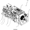
- FIG. 1 is an isometric view of the compressed air generation system 100, in accordance with an embodiment of the present disclosure.
- Multi-stage reciprocating compressor 1, primary mounting platform 2, secondary mounting platform 3, anti-vibration mount 4, compressor outlet 6, combi-cooler assembly 7 and after-cooler assembly 8 are indicated in Figure 1 .
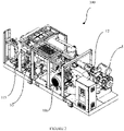
- Figure 2 is another isometric view of the compressed air generation system 100 of Figure 1 .
- Compressor suction filter 5, first drive motor 106, pump 10, surge tank 115 and control panel 12 are indicated in Figure 2 .
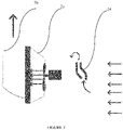
- FIG 3 is a schematic view of the combi-cooler assembly 7 of the present disclosure, wherein the combi-cooler casing 7a encloses the first intercooler 104a, the second intercooler 104b and the radiator assembly 105. Louvres 14 positioned at the air intake of the combi-cooler assembly 7 are also visible in Figure 2 .
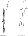
- Figure 4A is a side view of a fan used in the system of Figure 1 .
- Figure 4B is a close-up view showing the tip profile of the fan of Figure 4A , wherein the Blex tip profile is visible.
- Figure 5 is an isometric view of a combi-cooler assembly 7 of Figure 1 .
- Figure 6 is an exploded view of the combi-cooler assembly 7 of Figure 5 .
- Figure 7 is a schematic flow diagram of the air in the system 100.
- Figure 8 is a schematic flow diagram of the water in the system 100.
- a compressed air generation system 100 of the present disclosure will now be described in detail with reference to Figure 1 through Figure 8 .
- the compressed air generation system 100 comprises a multi-stage reciprocating compressor 1 and a combi-cooler assembly 7.
- the multi-stage compressor is a multi-stage reciprocating compressor 1, and includes a first reciprocating compression stage 102a, a second reciprocating compression stage 102b and a third reciprocating compression stage 102c.
- the first reciprocating compression stage 102a is configured to receive air at ambient pressure conditions.
- the first reciprocating compression stage 102a is configured to compress air to a first predetermined pressure value.
- the second reciprocating compression stage 102b is configured to be in fluid communication with the first reciprocating compression stage 102a.
- the second reciprocating compression stage 102b is configured to receive compressed air from the first reciprocating compression stage 102a,and is further configured to further compress air to a second predetermined pressure value.
- the third reciprocating compression stage 102c is configured to be in fluid communication with the second reciprocating compression stage 102b.
- the third reciprocating compression stage 102c is configured to receive compressed air from the second reciprocating compression stage 102b,and is further configured to further compress air to a third predetermined pressure value.
- Compression of air by the reciprocating compression stages 102a, 102b, 102c increases the temperature of the air.
- the resultant product of the compression thus is hot compressed air.
- the first predetermined pressure value ranges from 2.5 to 4 bar. In another embodiment, the second predetermined pressure value ranges from 12 to 16 bar. In yet another embodiment, the third predetermined pressure value ranges from 25 to 42 bar.
- the combi-cooler assembly 7 has at least two intercoolers 104a, 104b.
- the intercoolers 104a, 104b are configured to fluidly communicate with the reciprocating compression stages 102a, 102bto receive hot compressed air from the first reciprocating compression stage 102a and the second reciprocating compression stage 102b.
- the intercoolers 104a, 104b are configured to dissipate heat of the compressed air by passing the hot compressed air therethrough to generate relatively cooler compressed air.
- the compressed air generation system 100 is configured as a standalone plug-n-play unit.
- the multistage reciprocating compressor 1 and the combi-cooler assembly 7 are housed in a single enclosure.
- the compressed air generation system 100 is mounted on a primary mounting platform 2 having a secondary mounting platform 3 provided thereon, upon which the multi-stage reciprocating compressor 1 is configured to be mounted.
- a plurality of anti-vibrational mounts 4 is provided on the secondary mounting platform 3.
- the anti-vibrational mounts 4 are configured to allow mounting of the multi-stage reciprocating compressor 1 thereon, and are further configured to dissipate the vibrations exerted by the multi-stage reciprocating compressor 1.
- An air distribution circuit 200 connecting the multistage reciprocating compressor 1 and the combi-cooler assembly 7, is configured to facilitate fluid communication between the multistage reciprocating compressor 1 and the combi-cooler assembly 7. More specifically, the air distribution circuit 200 allows the hot compressed air to flow from the first reciprocating compression stage 102a to the first inter-cooler (104a) of the combi-cooler assembly 7, then the cooled compressed air from the first inter-cooler (104a) of the combi-cooler assembly 7 to the second reciprocating compression stage 102b, hot compressed air from the second reciprocating compression stage 102b to the second inter-cooler (104b) of the combi-cooler assembly 7, and thereafter cooled compressed air from the second inter-cooler (104b) of the combi-cooler assembly 7 to the third reciprocating compression stage 102c.
- the air distribution circuit 200 is a closed loop circuit, and recirculates the air therewithin during unloading stage. In another embodiment, the air distribution circuit 200 is an open loop circuit which continuously takes in air and discharges compressed air.
- the multistage reciprocating compressor 1 includes a piston passing through each of the first reciprocating compression stage 102a, the second reciprocating compression stage 102b, and the third reciprocating compression stage 102c, the three pistons being mounted on a crankshaft that is driven by a prime mover.
- the pistons are configured to be linearly displaced in corresponding cylinders in a reciprocating manner to facilitate compression of air in the compression stages 102a, 102b, 102c.
- the multistage reciprocating compressor 1 includes a crank case 130 crankshaft that supports the pistons and the cylinders of the three compression stages 102a, 102b, 102c.
- the compressed air generation system 100 includes a radiator circuit 300.
- the radiator circuit 300 is configured to be in fluid communication with the first reciprocating compression stage 102a, the second reciprocating compression stage 102b, the third reciprocating compression stage 102c, and the crank case 130.
- the radiator circuit 300 is configured to carry a coolant fluid therein to facilitate dissipation of heat from the first reciprocating compression stage 102a, the second reciprocating compression stage 102b, the third reciprocating compression stage 102c and the crank case 130.
- crank case 130 contains oil which not only aids in lubrication of the crankshaft but also helps in cooling of the crankshaft with the help of the radiator circuit 300 passing through the case.
- the radiator circuit 300 is a closed loop circuit.
- each of the intercoolers 104a, 104b and radiator 105 includes a plurality of channels that are configured to allow the hot compressed air and coolant fluid therethrough.
- the channels carrying the coolant fluid and the hot compressed air are positioned alternately, to facilitate heat exchange therebetween. More specifically, the channels carrying the coolant fluid is disposed between channels carrying the hot compressed air inside the combi-cooler (7) assembly.
- Each of the intercoolers 104a, 104b includes an inlet of intercooler 108a provided thereon to allow hot compressed air to flow in, and an outlet of intercooler 108b configured thereon allow cool compressed air to flow out.
- the combi-cooler assembly 7 includes a radiator 105 configured to be fluid communication with the radiator circuit 300 to receive the hot coolant fluid from a casing channels of the first reciprocating compression stage 102a, the second reciprocating compression stage 102b, the third reciprocating compression stage 102c and the crank case 130.
- the radiator 105 is configured to facilitate heat dissipation of the coolant fluid of the radiator circuit 300.
- the radiator 105 includes a plurality of channels mounted along the walls thereof. The channels are configured to allow the coolant fluid to pass therethrough.
- an inlet of radiator 105a and an outlet of radiator 105b are provided on the radiator 105 to allow the coolant fluid to flow through the radiator 105.
- the radiator 105 includes a pump 10 for facilitating circulation of the coolant therethrough.
- the radiator 105 is fluidly connected to a surge tank 115 storing the coolant therein, and the pump 10 allows the flow of the coolant to the radiator 105.
- the coolant fluid inside the radiator 105 circuit may be water, glycol mixed with water or any other composition with water .
- the compressed air generation system 100 includes a compressor suction filter 5 provided at the inlet of each of the first compression stage 102a to provide filtered air thereto.
- the compressor suction filter 5 filters out all the unwanted particles from the air to prevent clogging of the various components of the compressed air generation system 100.
- a buffer vessels 103a, 103b, 103c are provided at the outlet of each of the first reciprocating compression stage 102a, the second reciprocating compression stage 102b and the third reciprocating compression stage 102c.
- the buffer vessels 103a, 103b, 103c are configured to provide buffer gas to compensate the flow from the first reciprocating compression stage 102a, the second reciprocating compression stage 102b and the third reciprocating compression stage 103c, thereby regulating the output flow of the compressed air.
- the combi-cooler assembly 7 is located at a lateral end of the enclosure.
- the compressed air generation system 100 includes an after-cooler assembly 8 provided downstream of the final stage of compression of the third reciprocating compression stage 102c.
- the after-cooler assembly 8 comprises an after-cooler heat exchanger 110 and an after-cooler fan 118b configured to reduce the temperature of the hot compressed air let out from the third reciprocating compression stage 102c.
- a condensate recovery units 111a, 111b, 111c are provided downstream of the first inter-cooler (104a), the second inter-cooler (104b) and after-cooler assembly 8.
- the condensate recovery units 111a,111b,111c are configured to remove condensate matter formed as a result of cooling the hot compressed air in the inter-cooler 7 and after-cooler assembly 8.
- the condensate recovery units 111a, 111b, 111c are also helps in minimizing the pulsations during the compression in each stage of the compressed air.
- a pressure regulator 119 is provided downstream of the condensate recovery unit 111c to regulate the pressure of the compressed air during unloading stage and reduce to ambient conditions before passing it back to the first reciprocating compression stage 102a, thereby completing the closed loop.
- a solenoid valve 120 is provided downstream of the pressure regulator 119 to allow or stop the flow of the air from the pressure regulator 119 to the first reciprocating compression stage 102a during unload conditions.
- the compressed air generation system 100 includes a first drive motor 106 connected to the crankcase.
- the first drive motor 106 is configured to drive the crankshaft.
- the compressed air generation system 100 includes a blower fan 118a provided in the combi-cooler assembly 7.
- the blower fan 118a is configured to dissipate heat from the hot compressed air and the hot coolant fluid passing through the intercoolers 104a, 104b and the radiator 105.
- a second drive motor 107a is provided to drive the blower fan 118a.
- the second drive motor 107a is arranged inside the combi-cooler assembly 7.
- the compressed air generation system 100 includes a third drive motor 107b connected to the after-cooler assembly 8.
- the third drive motor 107b is configured to drive the after-cooler fan 118b.
- the after-cooler fan configured to dissipate heat from the hot compressed air passing through after-cooler heat exchanger 110 from the third reciprocating compression stage 102c.
- Both the combi-cooler assembly 7 and after-cooler heat exchanger 110 are air cooled by blowing atmospheric air over the combi-cooler assembly 7 and after-cooler heat exchanger 110 with the help of the blower fan 118a and after-cooler fan 118b.
- the compressed air generation system 100 includes an electronic control panel 121, 121a configured to control the operation of the compressed air generation system 100, by controlling the power supplied to the various drive motors, controlling the solenoid valves at various locations to maintain the flow uniform throughout the circuit.
- air at ambient conditions is supplied to the first reciprocating compression stage 102a after passing the air through the compressor suction filter 5.
- the crankshaft displaces the piston to facilitate compression of air in the first reciprocating compression stage 102a.
- Hot compressed air at a first predetermined value is discharged from the first compression stage 102a.
- the buffer vessels 103a, 103b, 103c compensate the flow of the discharged compressed air from each reciprocating compression stage to the subsequent stage of compressor. Since, the temperature of the compressed air is very high, it is passed to the combi-cooler assembly 7, wherein the compressed air is lead through the first intercooler 104a to help dissipation of the heat from the hot compressed air.
- the cooled compressed air is then passed to the condensate recovery unit 111a, helps in removing the condensate matter from the air before it enter into the second reciprocating compression stage 102b, where it is again compressed to a second predetermined value.
- the compressed air from the second reciprocating compression stage 102b is passed then to the combi-cooler assembly 7, wherein it is passed through the second intercooler 104b to help in dissipation of heat.
- the cooled compressed air is thereafter passed to the condensate recovery unit 111b, helps in removing the condensate matter from the air before it enter into the third reciprocating compression stage 102c , wherein it is further compressed to a third predetermined value.
- the resultant compressed air is then passed through the after-cooler assembly 8 where it is cooled to a desired temperature value. Thereafter, the cooled compressed air is passed through a condensate recovery unit 111c to allow removal of condensate matter from the air, and then discharged for a particular application. If there is no requirement of compressed air discharge, i.e., at a no-load condition, the pressure of the compressed air is reduced to ambient conditions and again passed to the first reciprocating compression stage 102a through the pressure regulator 119 and the solenoid valve 120.
- the coolant fluid flows from through the radiator circuit 300 to cool the components of the compressed air generation system 100 namely, the crank case 130, the first reciprocating compression stage 102a, the second reciprocating compression stage 102b, and the third reciprocating compression stage 102c of the multi-stage reciprocating compressor 1.
- the coolant fluid flows into the crank case 130 where it exchanges heat with the oil contained in the crank case 130, thereby cooling the oil.
- the coolant fluid passes through the multi-stage reciprocating compressor 1 to dissipate heat therefrom.
- the coolant fluid is thereafter made to pass through the radiator circuit 300, and passed into the inlet of radiator 105a.
- the heat of the coolant fluid while flowing through the radiator 105 is dissipated by the air blown by the blower fan 118a over the radiator 105.
- the coolant fluid condenses.
- the condensed coolant fluid flows out through the radiator exit and passed to the surge tank 115, from where it is passed back to the crank case 130, the first reciprocating compression stage 102a, the second reciprocating compression stage 102b, and the third reciprocating compression stage 102c of the multi-stage reciprocating compressor 1.
- vents 126 are provided at predetermined locations on the pistons.
- the vents 126 allow passage of any air content that may be leaked from the compressor during compression.
Landscapes
- Engineering & Computer Science (AREA)
- Mechanical Engineering (AREA)
- General Engineering & Computer Science (AREA)
- Physics & Mathematics (AREA)
- Thermal Sciences (AREA)
- Compressor (AREA)
- Compressors, Vaccum Pumps And Other Relevant Systems (AREA)
Abstract
Description
- The present disclosure relates to a compressed air generation system.
- The background information herein below relates to the present disclosure but is not necessarily prior art.
- For applications requiring very high-pressure compressed air at ambient temperature, a multi-stage compressor with one or more stages of intercooling is required. Typically, a multi-stage reciprocating compressor is incorporated for achieving high pressure ratios, which also generates high temperatures after compression. Water cooling of multi-stage reciprocating compressed air is to achieve desired cooling effect of the compressed air is well known, which require a separate plant for the cooling. Water cooling of compressed air require more space to build the heat-exchanger plant and complicated piping and valve arrangements to control the flow of water to the heat-exchanger plant. Hence more space required. The pressure ratio per stage is usually in the range 3-4 bar, and the adiabatically cooled air gets heated to high temperatures. Hence, an intercooler is placed immediately after the compression stage.
- While single-stage or two-stage compression plants are widely known, a plant with three stages compression with two stages of intercooling, providing an overall compression ratio of 1:40-1:50, is rarely realized as a single standalone unit. The unique challenges associated with such a standalone unit include the high magnitude of heat to be removed from the unit in an efficient manner, generation of noise within specified limits, providing ease of installation by minimizing the requirement for cooling ducts, and so on.
- Thus, compressed air generation system having multi-stage compression is required, which meets the aforementioned requirements.
- Some of the objects of the present disclosure, which at least one embodiment herein satisfies, are as follows.
- An object of the present disclosure is to ameliorate one or more problems of the prior art or to at least provide a useful alternative.
- Another object of the present disclosure is to provide a compressed air generation system having multi-stage compression.
- Yet another object of the present disclosure is to provide a compressed air generation system having multi-stage compression that is a standalone unit.
- Still another object of the present disclosure is to provide a compressed air generation system having multi-stage compression from which the high magnitude of heat generated is removed in an efficient manner.
- Yet another object of the present disclosure is to provide a compressed air generation system having multi-stage compression that generates noise within the stipulated limits.
- Another object of the present disclosure is to provide a compressed air generation system having multi-stage compression that provides ease of installation by minimizing the requirement for cooling ducts.
- Other objects and advantages of the present disclosure will be more apparent from the following description, which is not intended to limit the scope of the present disclosure.
- The present disclosure envisages a compressed air generation system. The compressed air generation system comprises a multi-stage reciprocating compressor including a first reciprocating compression stage, a second reciprocating compression stage, and a third reciprocating compression stage. The first reciprocating compression stage is configured to receive air at ambient pressure conditions. The first reciprocating compression stage is configured to compress air to a first predetermined pressure value. The second reciprocating compression stage is in fluid communication with the first reciprocating compression stage. The second reciprocating compression stage is configured to receive compressed air from the first reciprocating compression stage,and is further configured to further compress air to a second predetermined pressure value. The third reciprocating compression stage is in fluid communication with the second reciprocating compression stage. The third reciprocating compression stage is configured to receive compressed air from the second reciprocating compression stage, and further configured to further compress air to a third predetermined pressure value. The compressed air generation system further includes a combi-cooler assembly having at least two intercoolers fluidly communicating with the compressor to receive hot compressed air from the first compressor and the second compressor. The intercoolers are configured to dissipate heat of the compressed air by passing the hot compressed air therethrough to generate relatively cooler compressed air.
- A compressed air generation system having multistage compression. Present disclosure will now be described with the help of the accompanying drawing, in which:
-
Figure 1 is an isometric view of the compressed air generation system, in accordance with an embodiment of the present disclosure; -
Figure 2 is another isometric view of the compressed air generation system ofFigure 1 ; -
Figure 3 is a schematic view of the combi-cooler assembly of the present disclosure; -
Figure 4A is a side view of a blower fan used in the system ofFigure 1 ; -
Figure 4B is a close-up view showing the tip profile of the fan ofFigure 4A ; -
Figure 5 is an isometric view of a combi-cooler assembly ofFigure 1 ; -
Figure 6 is an exploded view of a combi-cooler assembly ofFigure 5 ; -
Figure 7 is a schematic flow diagram of the air in the system; and -
Figure 8 is a schematic flow diagram of the water in the system. - Embodiments, of the present disclosure, will now be described with reference to the accompanying drawing.
- Embodiments are provided so as to thoroughly and fully convey the scope of the present disclosure to the person skilled in the art. Numerous details are set forth, relating to specific components, and methods, to provide a complete understanding of embodiments of the present disclosure. It will be apparent to the person skilled in the art that the details provided in the embodiments should not be construed to limit the scope of the present disclosure. In some embodiments, well-known processes, well-known apparatus structures, and well-known techniques are not described in detail.
- The terminology used, in the present disclosure, is only for the purpose of explaining a particular embodiment and such terminology shall not be considered to limit the scope of the present disclosure. As used in the present disclosure, the forms "a", "an" and "the" may be intended to include the plural forms as well, unless the context clearly suggests otherwise. The terms "comprises", "comprising", "including" and "having," are open-ended transitional phrases and therefore specify the presence of stated features, elements, modules, units and/or components, but do not forbid the presence or addition of one or more other features, elements, components, and/or groups thereof.
- If used herein, the term "and/or" would include any and all combinations of one or more of the associated listed elements.
-
Figure 1 is an isometric view of the compressedair generation system 100, in accordance with an embodiment of the present disclosure. Multi-stage reciprocatingcompressor 1,primary mounting platform 2,secondary mounting platform 3,anti-vibration mount 4,compressor outlet 6, combi-cooler assembly 7 and after-cooler assembly 8 are indicated inFigure 1 . -
Figure 2 is another isometric view of the compressedair generation system 100 ofFigure 1 .Compressor suction filter 5,first drive motor 106,pump 10,surge tank 115 andcontrol panel 12 are indicated inFigure 2 . -
Figure 3 is a schematic view of the combi-cooler assembly 7 of the present disclosure, wherein the combi-cooler casing 7a encloses thefirst intercooler 104a, thesecond intercooler 104b and theradiator assembly 105. Louvres 14 positioned at the air intake of the combi-cooler assembly 7 are also visible inFigure 2 . -
Figure 4A is a side view of a fan used in the system ofFigure 1 .Figure 4B is a close-up view showing the tip profile of the fan ofFigure 4A , wherein the Blex tip profile is visible. -
Figure 5 is an isometric view of a combi-cooler assembly 7 ofFigure 1 . -
Figure 6 is an exploded view of the combi-cooler assembly 7 ofFigure 5 . -
Figure 7 is a schematic flow diagram of the air in thesystem 100. -
Figure 8 is a schematic flow diagram of the water in thesystem 100. - Other components for air and water handling, including pulsation bottles, safety valves, cylinder suction valves, moisture separators, oil pump, oil filter, non-return valve, drain terminals, pressure regulator, airline filter, pipes, hoses, inlet and outlet manifolds, inlet and outlet headers, and so on, are schematically illustrated in the flow diagrams of
Figures 7 and8 . - A compressed
air generation system 100 of the present disclosure will now be described in detail with reference toFigure 1 through Figure 8 . - The compressed
air generation system 100 comprises amulti-stage reciprocating compressor 1 and a combi-cooler assembly 7. In an embodiment, the multi-stage compressor is amulti-stage reciprocating compressor 1, and includes a firstreciprocating compression stage 102a, a secondreciprocating compression stage 102b and a thirdreciprocating compression stage 102c. - The first
reciprocating compression stage 102a is configured to receive air at ambient pressure conditions. The firstreciprocating compression stage 102a is configured to compress air to a first predetermined pressure value. The secondreciprocating compression stage 102b is configured to be in fluid communication with the firstreciprocating compression stage 102a. The secondreciprocating compression stage 102b is configured to receive compressed air from the firstreciprocating compression stage 102a,and is further configured to further compress air to a second predetermined pressure value. The thirdreciprocating compression stage 102c is configured to be in fluid communication with the secondreciprocating compression stage 102b. The thirdreciprocating compression stage 102c is configured to receive compressed air from the secondreciprocating compression stage 102b,and is further configured to further compress air to a third predetermined pressure value. - Compression of air by the
reciprocating compression stages - In one embodiment, wherein the first predetermined pressure value ranges from 2.5 to 4 bar. In another embodiment, the second predetermined pressure value ranges from 12 to 16 bar. In yet another embodiment, the third predetermined pressure value ranges from 25 to 42 bar.
- The combi-
cooler assembly 7 has at least twointercoolers intercoolers reciprocating compression stages 102a, 102bto receive hot compressed air from the firstreciprocating compression stage 102a and the secondreciprocating compression stage 102b. Theintercoolers - In a preferred embodiment, of the present disclosure, the compressed
air generation system 100 is configured as a standalone plug-n-play unit. In another embodiment, themultistage reciprocating compressor 1 and the combi-cooler assembly 7 are housed in a single enclosure. In a preferred embodiment, the compressedair generation system 100 is mounted on aprimary mounting platform 2 having asecondary mounting platform 3 provided thereon, upon which themulti-stage reciprocating compressor 1 is configured to be mounted. Preferably, a plurality ofanti-vibrational mounts 4 is provided on thesecondary mounting platform 3. The anti-vibrational mounts 4 are configured to allow mounting of themulti-stage reciprocating compressor 1 thereon, and are further configured to dissipate the vibrations exerted by themulti-stage reciprocating compressor 1. - An
air distribution circuit 200, connecting themultistage reciprocating compressor 1 and the combi-cooler assembly 7, is configured to facilitate fluid communication between themultistage reciprocating compressor 1 and the combi-cooler assembly 7. More specifically, theair distribution circuit 200 allows the hot compressed air to flow from the firstreciprocating compression stage 102a to the first inter-cooler (104a) of the combi-cooler assembly 7, then the cooled compressed air from the first inter-cooler (104a) of the combi-cooler assembly 7 to the secondreciprocating compression stage 102b, hot compressed air from the secondreciprocating compression stage 102b to the second inter-cooler (104b) of the combi-cooler assembly 7, and thereafter cooled compressed air from the second inter-cooler (104b) of the combi-cooler assembly 7 to the thirdreciprocating compression stage 102c. - In a preferred embodiment, the
air distribution circuit 200 is a closed loop circuit, and recirculates the air therewithin during unloading stage. In another embodiment, theair distribution circuit 200 is an open loop circuit which continuously takes in air and discharges compressed air. - In an embodiment, the
multistage reciprocating compressor 1 includes a piston passing through each of the firstreciprocating compression stage 102a, the secondreciprocating compression stage 102b, and the thirdreciprocating compression stage 102c, the three pistons being mounted on a crankshaft that is driven by a prime mover. The pistons are configured to be linearly displaced in corresponding cylinders in a reciprocating manner to facilitate compression of air in thecompression stages multistage reciprocating compressor 1 includes a crankcase 130 crankshaft that supports the pistons and the cylinders of the threecompression stages - In a preferred embodiment, the compressed
air generation system 100 includes aradiator circuit 300. Theradiator circuit 300 is configured to be in fluid communication with the firstreciprocating compression stage 102a, the secondreciprocating compression stage 102b, the thirdreciprocating compression stage 102c, and the crankcase 130. Theradiator circuit 300 is configured to carry a coolant fluid therein to facilitate dissipation of heat from the firstreciprocating compression stage 102a, the secondreciprocating compression stage 102b, the thirdreciprocating compression stage 102c and the crankcase 130. - In an embodiment, the crank
case 130 contains oil which not only aids in lubrication of the crankshaft but also helps in cooling of the crankshaft with the help of theradiator circuit 300 passing through the case. - In an embodiment, the
radiator circuit 300 is a closed loop circuit. - In one embodiment, each of the
intercoolers radiator 105 includes a plurality of channels that are configured to allow the hot compressed air and coolant fluid therethrough. The channels carrying the coolant fluid and the hot compressed air are positioned alternately, to facilitate heat exchange therebetween. More specifically, the channels carrying the coolant fluid is disposed between channels carrying the hot compressed air inside the combi-cooler (7) assembly. - Each of the
intercoolers intercooler 108a provided thereon to allow hot compressed air to flow in, and an outlet ofintercooler 108b configured thereon allow cool compressed air to flow out. - In an embodiment, the combi-
cooler assembly 7 includes aradiator 105 configured to be fluid communication with theradiator circuit 300 to receive the hot coolant fluid from a casing channels of the firstreciprocating compression stage 102a, the secondreciprocating compression stage 102b, the thirdreciprocating compression stage 102c and the crankcase 130. Theradiator 105 is configured to facilitate heat dissipation of the coolant fluid of theradiator circuit 300. In an embodiment, theradiator 105 includes a plurality of channels mounted along the walls thereof. The channels are configured to allow the coolant fluid to pass therethrough. In another embodiment, an inlet ofradiator 105a and an outlet ofradiator 105b are provided on theradiator 105 to allow the coolant fluid to flow through theradiator 105. - The
radiator 105 includes apump 10 for facilitating circulation of the coolant therethrough. In an embodiment, theradiator 105 is fluidly connected to asurge tank 115 storing the coolant therein, and thepump 10 allows the flow of the coolant to theradiator 105. The coolant fluid inside theradiator 105 circuit may be water, glycol mixed with water or any other composition with water . - In one embodiment, the compressed
air generation system 100 includes acompressor suction filter 5 provided at the inlet of each of thefirst compression stage 102a to provide filtered air thereto. Thecompressor suction filter 5 filters out all the unwanted particles from the air to prevent clogging of the various components of the compressedair generation system 100. - In an embodiment, a
buffer vessels reciprocating compression stage 102a, the secondreciprocating compression stage 102b and the thirdreciprocating compression stage 102c. Thebuffer vessels reciprocating compression stage 102a, the secondreciprocating compression stage 102b and the thirdreciprocating compression stage 103c, thereby regulating the output flow of the compressed air. - In an embodiment, the combi-
cooler assembly 7 is located at a lateral end of the enclosure. - In one embodiment, the compressed
air generation system 100 includes an after-cooler assembly 8 provided downstream of the final stage of compression of the thirdreciprocating compression stage 102c. The after-cooler assembly 8 comprises an after-cooler heat exchanger 110 and an after-cooler fan 118b configured to reduce the temperature of the hot compressed air let out from the thirdreciprocating compression stage 102c. - In an embodiment, a
condensate recovery units cooler assembly 8. Thecondensate recovery units inter-cooler 7 and after-cooler assembly 8. Thecondensate recovery units - In an embodiment, a
pressure regulator 119 is provided downstream of thecondensate recovery unit 111c to regulate the pressure of the compressed air during unloading stage and reduce to ambient conditions before passing it back to the firstreciprocating compression stage 102a, thereby completing the closed loop. Preferably, asolenoid valve 120 is provided downstream of thepressure regulator 119 to allow or stop the flow of the air from thepressure regulator 119 to the firstreciprocating compression stage 102a during unload conditions. - In an embodiment, the compressed
air generation system 100 includes afirst drive motor 106 connected to the crankcase. Thefirst drive motor 106 is configured to drive the crankshaft. - In an embodiment, the compressed
air generation system 100 includes ablower fan 118a provided in the combi-cooler assembly 7. Theblower fan 118a is configured to dissipate heat from the hot compressed air and the hot coolant fluid passing through theintercoolers radiator 105. Asecond drive motor 107a is provided to drive theblower fan 118a. Thesecond drive motor 107a is arranged inside the combi-cooler assembly 7.In an embodiment, the compressedair generation system 100 includes athird drive motor 107b connected to the after-cooler assembly 8. Thethird drive motor 107b is configured to drive the after-cooler fan 118b. The after-cooler fan configured to dissipate heat from the hot compressed air passing through after-cooler heat exchanger 110 from the thirdreciprocating compression stage 102c. Both the combi-cooler assembly 7 and after-cooler heat exchanger 110 are air cooled by blowing atmospheric air over the combi-cooler assembly 7 and after-cooler heat exchanger 110 with the help of theblower fan 118a and after-cooler fan 118b. - In a preferred embodiment, the compressed
air generation system 100 includes anelectronic control panel air generation system 100, by controlling the power supplied to the various drive motors, controlling the solenoid valves at various locations to maintain the flow uniform throughout the circuit. - In an operative configuration, explained with reference to
Figure 7 , air at ambient conditions is supplied to the firstreciprocating compression stage 102a after passing the air through thecompressor suction filter 5. The crankshaft displaces the piston to facilitate compression of air in the firstreciprocating compression stage 102a. Hot compressed air at a first predetermined value is discharged from thefirst compression stage 102a. Thebuffer vessels cooler assembly 7, wherein the compressed air is lead through thefirst intercooler 104a to help dissipation of the heat from the hot compressed air. The cooled compressed air is then passed to thecondensate recovery unit 111a, helps in removing the condensate matter from the air before it enter into the secondreciprocating compression stage 102b, where it is again compressed to a second predetermined value. The compressed air from the secondreciprocating compression stage 102b is passed then to the combi-cooler assembly 7, wherein it is passed through thesecond intercooler 104b to help in dissipation of heat. The cooled compressed air is thereafter passed to the condensate recovery unit 111b, helps in removing the condensate matter from the air before it enter into the thirdreciprocating compression stage 102c , wherein it is further compressed to a third predetermined value. - The resultant compressed air is then passed through the after-
cooler assembly 8 where it is cooled to a desired temperature value. Thereafter, the cooled compressed air is passed through acondensate recovery unit 111c to allow removal of condensate matter from the air, and then discharged for a particular application. If there is no requirement of compressed air discharge, i.e., at a no-load condition, the pressure of the compressed air is reduced to ambient conditions and again passed to the firstreciprocating compression stage 102a through thepressure regulator 119 and thesolenoid valve 120. - In another operative configuration, as depicted by
Figure 8 , the coolant fluid flows from through theradiator circuit 300 to cool the components of the compressedair generation system 100 namely, the crankcase 130, the firstreciprocating compression stage 102a, the secondreciprocating compression stage 102b, and the thirdreciprocating compression stage 102c of themulti-stage reciprocating compressor 1. In an embodiment, the coolant fluid flows into the crankcase 130 where it exchanges heat with the oil contained in thecrank case 130, thereby cooling the oil. Similarly, the coolant fluid passes through themulti-stage reciprocating compressor 1 to dissipate heat therefrom. - The coolant fluid is thereafter made to pass through the
radiator circuit 300, and passed into the inlet ofradiator 105a. The heat of the coolant fluid while flowing through theradiator 105 is dissipated by the air blown by theblower fan 118a over theradiator 105. The coolant fluid condenses. The condensed coolant fluid flows out through the radiator exit and passed to thesurge tank 115, from where it is passed back to the crankcase 130, the firstreciprocating compression stage 102a, the secondreciprocating compression stage 102b, and the thirdreciprocating compression stage 102c of themulti-stage reciprocating compressor 1. - In an embodiment, vents 126 are provided at predetermined locations on the pistons. The
vents 126 allow passage of any air content that may be leaked from the compressor during compression. - The foregoing description of the embodiments has been provided for purposes of illustration and not intended to limit the scope of the present disclosure. Individual components of a particular embodiment are generally not limited to that particular embodiment but are interchangeable. Such variations are not to be regarded as a departure from the present disclosure, and all such modifications are considered to be within the scope of the present disclosure.
- The present disclosure described hereinabove has several technical advantages including, but not limited to, the realization of a compressed
air generation system 100 having multi-stage compression: - which is a standalone, plug-and-play unit;
- from which the high magnitude of heat generated is removed in an efficient manner;
- that generates noise within the stipulated limits; and
- that provides ease of installation by minimizing the requirement for cooling ducts.
- The embodiments herein and the various features and advantageous details thereof are explained with reference to the non-limiting embodiments in the following description. Descriptions of well-known components and processing techniques are omitted so as to not unnecessarily obscure the embodiments herein. The examples used herein are intended merely to facilitate an understanding of ways in which the embodiments herein may be practiced and to further enable those of skill in the art to practice the embodiments herein. Accordingly, the examples should not be construed as limiting the scope of the embodiments herein.
- The foregoing description of the specific embodiments so fully reveal the general nature of the embodiments herein that others can, by applying current knowledge, readily modify and/or adapt for various applications such specific embodiments without departing from the generic concept, and, therefore, such adaptations and modifications should and are intended to be comprehended within the meaning and range of equivalents of the disclosed embodiments. It is to be understood that the phraseology or terminology employed herein is for the purpose of description and not of limitation. Therefore, while the embodiments herein have been described in terms of preferred embodiments, those skilled in the art will recognize that the embodiments herein can be practiced with modification within the spirit and scope of the embodiments as described herein.
- The use of the expression "at least" or "at least one" suggests the use of one or more elements or ingredients or quantities, as the use may be in the embodiment of the disclosure to achieve one or more of the desired objects or results.
- Any discussion of materials, devices, articles or the like that has been included in this specification is solely for the purpose of providing a context for the disclosure. It is not to be taken as an admission that any or all of these matters form a part of the prior art base or were common general knowledge in the field relevant to the disclosure as it existed anywhere before the priority date of this application.
- While considerable emphasis has been placed herein on the components and component parts of the preferred embodiments, it will be appreciated that many embodiments can be made and that many changes can be made in the preferred embodiments without departing from the principles of the disclosure. These and other changes in the preferred embodiment as well as other embodiments of the disclosure will be apparent to those skilled in the art from the disclosure herein, whereby it is to be distinctly understood that the foregoing descriptive matter is to be interpreted merely as illustrative of the disclosure and not as a limitation.
Claims (16)
- A compressed air generation system (100) comprising:a multistage reciprocating compressor (1) including:a first reciprocating compression stage (102a) configured to receive air at ambient pressure conditions, said first reciprocating compression stage (102a) configured to compress air to a first predetermined pressure value;a second reciprocating compression stage (102b) in fluid communication with said first reciprocating compression stage (102a), said second reciprocating compression stage (102b) configured to receive compressed air from said first reciprocating compression stage (102a), and wherein said second reciprocating compression stage (102b) is configured to compress received compressed air from said first reciprocating compression stage (102a) to a second predetermined pressure value; anda third reciprocating compression stage (102c) in fluid communication with said second reciprocating compression stage (102b), said third reciprocating compression stage (102c) is configured to receive compressed air from said second reciprocating compression stage (102b), and wherein said third reciprocating compression stage (102c) is configured to compress received compressed air from said second reciprocating compression stage (102b) to a third predetermined pressure value;a combi-cooler assembly (7) comprising at least two intercoolers (104a, 104b), said intercoolers (104a, 104b) being in fluid communication with said first and second reciprocating compression stages (102a, 102b) to receive hot compressed air from said first reciprocating compression stage (102a) and said second reciprocating compression stage (102b), said intercoolers (104a, 104b) being configured to dissipate heat of the compressed air by passing the hot compressed air therethrough to generate relatively cooler compressed air for a next subsequent stage;an after-cooler assembly (8) configured to be in communication with the third reciprocating compression stage (102c), wherein the after-cooler assembly (8) is configured to reduce the temperature of the hot compressed air coming out from the third reciprocating compression stage (102c).
- The compressed air generation system (100) as claimed in claim 1, characterized in that said multistage reciprocating compressor (1), said combi-cooler assembly (7) and said after-cooler assembly (8) are housed in a single enclosure.
- The compressed air generation system (100) as claimed in claim 1 or 2, characterized in that said compressed air generation system (100) includes an air distribution circuit (200) configured to facilitate fluid communication between said multistage reciprocating compressor (1) and said combi-cooler assembly (7).
- The compressed air generation system (100) as claimed in claim 3, characterized in that said air distribution circuit (200) is a closed loop circuit.
- The compressed air generation system (100) as claimed in any of claims 1 to 4, characterized in that said compressed air generation system (100) further including a radiator circuit (300) in fluid communication with said first reciprocating compression stage (102a), said second reciprocating compression stage (102b), said third reciprocating compression stage (102c) and a crankcase (130) which makes part of said multistage reciprocating compressor (1); and in that said radiator circuit (300) is configured to carry a coolant fluid therein to facilitate dissipation of heat from said first reciprocating compression stage (102a), said second reciprocating compression stage (102b), said third reciprocating compression stage (102c) and said crankcase (130).
- The compressed air generation system (100) as claimed in claim 5, characterized in that said radiator circuit (300) is a closed loop circuit.
- The compressed air generation system (100) as claimed in claim 5 or 6, characterized in that each of said intercoolers (104a, 104b) and a radiator (105) in fluid communication with said radiator circuit (300) or making part therefrom include a plurality of channels configured to allow the hot compressed air and the coolant fluid to pass through alternately, to facilitate heat exchange therebetween.
- The compressed air generation system (100) as claimed in any one of the preceding claims 1 to 6, characterized in that said combi-cooler assembly (7) includes a radiator (105) in fluid communication with said radiator circuit (300) or making part therefrom to receive the hot coolant fluid, wherein said radiator (105) is configured to facilitate dissipation of heat from the coolant fluid of said radiator circuit (300).
- The compressed air generation system (100) as claimed in claim 7 or 8, characterized in that said radiator (105) includes a plurality of channels mounted along the walls thereof, said channels configured to allow said coolant fluid to pass therethrough.
- The compressed air generation system (100) as claimed in claim 7 or 8, characterized in that said radiator (105) includes a pump (10) for facilitating circulation of said coolant fluid therethrough.
- The compressed air generation system (100) as claimed in claim 5, characterized in that the coolant fluid comprises one or more selected from the group comprising: water, glycol mixed with water and any other composition with water.
- The compressed air generation system (100) as claimed in any of the preceding claims, characterized in that said compressed air generation system further comprising a buffer vessel (103a, 103b, 103c) provided at the outlet of each of said first reciprocating compression stage (102a) and said second reciprocating compression stage (102b) and said third reciprocating compression stage (102c), said buffer vessels (103a, 103b, 103c) configured to provide flow compensation from said first reciprocating compression stage (102a) and said second reciprocating compression stage (102b) and said third reciprocating compression stage (102c).
- The compressed air generation system (100) as claimed in claim 2, characterized in that said combi-cooler assembly (7) is located at a lateral end of said enclosure.
- The compressed air generation system (100) as claimed in any of the preceding claims, characterized in that a condensate recovery units (111a,111b,111c) are provided downstream of said inter-coolers (104a, 104b) and said after-cooler assembly (8), said condensate recovery units (111a,111b,111c) being configured to remove condensate matter formed as a result of cooling the hot compressed air in the inter-coolers (104a, 104b) and the after-cooler assembly (8).
- The compressed air generation system (100) as claimed in claim 7 or 8, characterized in that said compressed air generation system further including a blower fan (118a) disposed within said combi-cooler assembly (7), said blower fan (118a) being configured to dissipate heat from the compressed air passing through said intercoolers (104a, 104b) and said radiator (105).
- The compressed air generation system (100) as claimed in any of the preceding claims, characterized in that said compressed air generation system further includes a surge tank (115) configured to store the coolant fluid therein.
Applications Claiming Priority (1)
| Application Number | Priority Date | Filing Date | Title |
|---|---|---|---|
| IN202121018988 | 2021-04-24 |
Publications (3)
| Publication Number | Publication Date |
|---|---|
| EP4080048A1 true EP4080048A1 (en) | 2022-10-26 |
| EP4080048B1 EP4080048B1 (en) | 2025-04-09 |
| EP4080048C0 EP4080048C0 (en) | 2025-04-09 |
Family
ID=81346323
Family Applications (1)
| Application Number | Title | Priority Date | Filing Date |
|---|---|---|---|
| EP22169497.9A Active EP4080048B1 (en) | 2021-04-24 | 2022-04-22 | A compressed air generation system |
Country Status (3)
| Country | Link |
|---|---|
| US (1) | US12123407B2 (en) |
| EP (1) | EP4080048B1 (en) |
| CN (1) | CN114738236B (en) |
Families Citing this family (1)
| Publication number | Priority date | Publication date | Assignee | Title |
|---|---|---|---|---|
| US20240318786A1 (en) * | 2023-03-23 | 2024-09-26 | Clean Recompression, LLC | Method and System For Compact and Hyper Mobile Recompression |
Citations (3)
| Publication number | Priority date | Publication date | Assignee | Title |
|---|---|---|---|---|
| US3216648A (en) * | 1962-04-02 | 1965-11-09 | Stephen H Ford | Automatic blowdown system for compressors |
| US20030215339A1 (en) * | 2002-05-20 | 2003-11-20 | Grimmer John E. | Multi-stage gas compressor system |
| US20180154302A1 (en) * | 2016-10-25 | 2018-06-07 | Atlas Copco Airpower, Naamloze Vennootschap | Compressor installation with drying device for compressed gas and method for drying compressed gas |
Family Cites Families (40)
| Publication number | Priority date | Publication date | Assignee | Title |
|---|---|---|---|---|
| US1473314A (en) * | 1923-06-16 | 1923-11-06 | Poccia Loreto | Air compressor |
| US2738659A (en) * | 1952-11-03 | 1956-03-20 | Karl G Heed | Air compressor and cooler |
| US3096927A (en) * | 1959-10-13 | 1963-07-09 | Wahl Hermann | Relieving device for multiple stage compressors |
| US3462074A (en) * | 1968-02-23 | 1969-08-19 | John E Grimmer | Air compressor apparatus and method |
| US4022550A (en) * | 1976-03-19 | 1977-05-10 | Gardner-Denver Company | Enclosed compressor unit |
| US4097202A (en) * | 1976-06-21 | 1978-06-27 | Billy Frank Price | Auxiliary compressor assembly |
| JPS61145887U (en) * | 1985-03-04 | 1986-09-09 | ||
| US5203680A (en) * | 1989-10-27 | 1993-04-20 | Gas Jack, Inc. | Integral gas compressor and internal combustion engine |
| US5106270A (en) * | 1991-01-10 | 1992-04-21 | Westinghouse Air Brake Company | Air-cooled air compressor |
| US5386873A (en) * | 1993-06-09 | 1995-02-07 | Ingersoll-Rand Company | Cooling system for engine-driven multi-stage centrifugal compressor |
| JP3474704B2 (en) * | 1996-03-29 | 2003-12-08 | アネスト岩田株式会社 | Cooling structure of two-stage air-cooled reciprocating compressor |
| US5947711A (en) * | 1997-04-16 | 1999-09-07 | Gardner Denver Machinery, Inc. | Rotary screw air compressor having a separator and a cooler fan assembly |
| US6203285B1 (en) * | 1998-05-18 | 2001-03-20 | Westinghouse Air Brake Company | Compressor intercooler unloader arrangement |
| JP4003378B2 (en) * | 2000-06-30 | 2007-11-07 | 株式会社日立プラントテクノロジー | Screw compressor |
| US6447264B1 (en) * | 2001-02-05 | 2002-09-10 | Ingersoll-Rand Company | Compressor system |
| US6692235B2 (en) * | 2001-07-30 | 2004-02-17 | Cooper Cameron Corporation | Air cooled packaged multi-stage centrifugal compressor system |
| US6629825B2 (en) * | 2001-11-05 | 2003-10-07 | Ingersoll-Rand Company | Integrated air compressor |
| CN1916410B (en) * | 2005-08-19 | 2010-10-06 | 科拉克集团公开公司 | Multi-stage oil-free gas compressor |
| US20070044938A1 (en) * | 2005-08-26 | 2007-03-01 | Farley Mary L | Dual surge tank for vehicle cooling system |
| CN107084036B (en) * | 2008-04-16 | 2019-10-22 | 米提亚·维克托·辛德克斯 | Reciprocating machines and other devices |
| US20090297368A1 (en) * | 2008-06-03 | 2009-12-03 | Wabtec Holding Corp. | Single Piece Water Over Air Intercooler for a Reciprocating Air Compressor |
| JP5248373B2 (en) * | 2009-03-11 | 2013-07-31 | 株式会社日立産機システム | Water jet air compressor |
| JP2010275939A (en) * | 2009-05-29 | 2010-12-09 | Hitachi Industrial Equipment Systems Co Ltd | Water-cooled oil-free air compressor |
| DE102010008063A1 (en) * | 2010-02-16 | 2011-08-18 | WABCO GmbH, 30453 | Compressed air compressor and method for operating an air compressor |
| US9989279B2 (en) * | 2010-04-29 | 2018-06-05 | Carrier Corporation | Refrigerant vapor compression system with intercooler |
| KR101237972B1 (en) * | 2010-10-25 | 2013-02-28 | 삼성테크윈 주식회사 | Compressor |
| US20120180477A1 (en) * | 2011-01-14 | 2012-07-19 | Gregory Alan Marsh | Thermal management systems and methods |
| US9897082B2 (en) * | 2011-09-15 | 2018-02-20 | General Electric Company | Air compressor prognostic system |
| GB2500871B (en) * | 2012-04-05 | 2017-03-01 | Ford Global Tech Llc | An Air to Liquid Heat Exchanger |
| US8534039B1 (en) * | 2012-04-16 | 2013-09-17 | TAS Energy, Inc. | High performance air-cooled combined cycle power plant with dual working fluid bottoming cycle and integrated capacity control |
| DE202013104306U1 (en) * | 2013-09-20 | 2013-10-31 | Gardner Denver Deutschland Gmbh | Dry running compressor for the production of compressed air |
| US20150110647A1 (en) * | 2013-10-18 | 2015-04-23 | Steven Lee Wilhelm | Compressors |
| US20150285264A1 (en) * | 2014-04-07 | 2015-10-08 | Union Pacific Railroad Company | Air compressor with self contained cooling system |
| US9951763B2 (en) * | 2014-05-09 | 2018-04-24 | Westinghouse Air Brake Technologies Corporation | Compressor cooled by a temperature controlled fan |
| WO2017161118A1 (en) * | 2016-03-17 | 2017-09-21 | Powerphase Llc | Gas turbine modular air cooling system |
| CN108700055B (en) * | 2016-05-09 | 2019-10-18 | 株式会社日立产机系统 | Box compressor |
| US10153524B2 (en) * | 2016-06-30 | 2018-12-11 | Faraday&Future Inc. | Vehicle cooling system using gravity based fluid flow |
| US10900499B2 (en) * | 2017-02-06 | 2021-01-26 | Ford Global Technologies, Llc | Cooling fans for engine cooling system |
| DE102017107602B3 (en) * | 2017-04-10 | 2018-09-20 | Gardner Denver Deutschland Gmbh | Compressor system with internal air-water cooling |
| EP3768980B1 (en) * | 2018-03-20 | 2026-04-01 | Enersize Oy | A method for designing, gauging and optimizing a multilpe compressor system with respect to energy efficiency |
-
2022
- 2022-03-31 CN CN202210344674.8A patent/CN114738236B/en active Active
- 2022-04-05 US US17/713,272 patent/US12123407B2/en active Active
- 2022-04-22 EP EP22169497.9A patent/EP4080048B1/en active Active
Patent Citations (3)
| Publication number | Priority date | Publication date | Assignee | Title |
|---|---|---|---|---|
| US3216648A (en) * | 1962-04-02 | 1965-11-09 | Stephen H Ford | Automatic blowdown system for compressors |
| US20030215339A1 (en) * | 2002-05-20 | 2003-11-20 | Grimmer John E. | Multi-stage gas compressor system |
| US20180154302A1 (en) * | 2016-10-25 | 2018-06-07 | Atlas Copco Airpower, Naamloze Vennootschap | Compressor installation with drying device for compressed gas and method for drying compressed gas |
Also Published As
| Publication number | Publication date |
|---|---|
| CN114738236B (en) | 2024-04-26 |
| US20220341412A1 (en) | 2022-10-27 |
| CN114738236A (en) | 2022-07-12 |
| EP4080048B1 (en) | 2025-04-09 |
| US12123407B2 (en) | 2024-10-22 |
| EP4080048C0 (en) | 2025-04-09 |
Similar Documents
| Publication | Publication Date | Title |
|---|---|---|
| US6551082B2 (en) | Oil free type screw compressor | |
| US7717069B2 (en) | Engine cooling system having two cooling circuits | |
| US6692235B2 (en) | Air cooled packaged multi-stage centrifugal compressor system | |
| EP3064866A1 (en) | Modulated oversized compressor configuration for flash gas bypass in a carbon dioxide refrigeration system | |
| JP2008163926A (en) | Oil-free screw compressor | |
| EP2789855B1 (en) | Temperature control for compressor | |
| CN101542215A (en) | A compressor | |
| EP4080048A1 (en) | A compressed air generation system | |
| US6609484B2 (en) | Engine cooling system | |
| WO2019197927A1 (en) | Oil-injected screw compressor installation | |
| US11639824B2 (en) | Process for enhanced closed-circuit cooling system | |
| US20150086392A1 (en) | Dry running compressor for creating compressed air | |
| JP2718555B2 (en) | Air-cooled oilless rotary two-stage compressor | |
| EP0397760B1 (en) | Method and apparatus for recovery of refrigerant | |
| BE1014461A3 (en) | Oil injected screw compressor, has separate oil supply system with cooler for lubricating rotor bearings | |
| JP2011153760A (en) | Two-stage compressor | |
| US10760490B2 (en) | Gas turbine efficiency and power augmentation system's modular air cooling system and methods of using the same | |
| CN215333650U (en) | A multifunctional cooling system for centrifugal compressors | |
| CN220343282U (en) | Compressed air refrigeration oxygenation equipment | |
| BE1013684A3 (en) | Compressor with at least one air-cooled after-cooler | |
| US11846457B2 (en) | Transportation refrigeration modular unit | |
| JP2025176530A (en) | Compressor | |
| JPH01310189A (en) | Cooler for oil free screw compressor | |
| KR102271259B1 (en) | Air cooling three stage turbo air compressor | |
| JPH07217579A (en) | Screw compressor cooling system |
Legal Events
| Date | Code | Title | Description |
|---|---|---|---|
| PUAI | Public reference made under article 153(3) epc to a published international application that has entered the european phase |
Free format text: ORIGINAL CODE: 0009012 |
|
| STAA | Information on the status of an ep patent application or granted ep patent |
Free format text: STATUS: THE APPLICATION HAS BEEN PUBLISHED |
|
| AK | Designated contracting states |
Kind code of ref document: A1 Designated state(s): AL AT BE BG CH CY CZ DE DK EE ES FI FR GB GR HR HU IE IS IT LI LT LU LV MC MK MT NL NO PL PT RO RS SE SI SK SM TR |
|
| STAA | Information on the status of an ep patent application or granted ep patent |
Free format text: STATUS: REQUEST FOR EXAMINATION WAS MADE |
|
| 17P | Request for examination filed |
Effective date: 20230425 |
|
| RBV | Designated contracting states (corrected) |
Designated state(s): AL AT BE BG CH CY CZ DE DK EE ES FI FR GB GR HR HU IE IS IT LI LT LU LV MC MK MT NL NO PL PT RO RS SE SI SK SM TR |
|
| GRAP | Despatch of communication of intention to grant a patent |
Free format text: ORIGINAL CODE: EPIDOSNIGR1 |
|
| STAA | Information on the status of an ep patent application or granted ep patent |
Free format text: STATUS: GRANT OF PATENT IS INTENDED |
|
| INTG | Intention to grant announced |
Effective date: 20241030 |
|
| GRAS | Grant fee paid |
Free format text: ORIGINAL CODE: EPIDOSNIGR3 |
|
| RAP3 | Party data changed (applicant data changed or rights of an application transferred) |
Owner name: ATLAS COPCO (INDIA) PRIVATE LIMITED |
|
| GRAA | (expected) grant |
Free format text: ORIGINAL CODE: 0009210 |
|
| STAA | Information on the status of an ep patent application or granted ep patent |
Free format text: STATUS: THE PATENT HAS BEEN GRANTED |
|
| RAP1 | Party data changed (applicant data changed or rights of an application transferred) |
Owner name: ATLAS COPCO AIRPOWER, NAAMLOZE VENNOOTSCHAP |
|
| AK | Designated contracting states |
Kind code of ref document: B1 Designated state(s): AL AT BE BG CH CY CZ DE DK EE ES FI FR GB GR HR HU IE IS IT LI LT LU LV MC MK MT NL NO PL PT RO RS SE SI SK SM TR |
|
| REG | Reference to a national code |
Ref country code: GB Ref legal event code: FG4D |
|
| REG | Reference to a national code |
Ref country code: CH Ref legal event code: EP |
|
| REG | Reference to a national code |
Ref country code: DE Ref legal event code: R096 Ref document number: 602022012775 Country of ref document: DE |
|
| REG | Reference to a national code |
Ref country code: IE Ref legal event code: FG4D |
|
| U01 | Request for unitary effect filed |
Effective date: 20250505 |
|
| U07 | Unitary effect registered |
Designated state(s): AT BE BG DE DK EE FI FR IT LT LU LV MT NL PT RO SE SI Effective date: 20250522 |
|
| U20 | Renewal fee for the european patent with unitary effect paid |
Year of fee payment: 4 Effective date: 20250527 |
|
| PG25 | Lapsed in a contracting state [announced via postgrant information from national office to epo] |
Ref country code: ES Free format text: LAPSE BECAUSE OF FAILURE TO SUBMIT A TRANSLATION OF THE DESCRIPTION OR TO PAY THE FEE WITHIN THE PRESCRIBED TIME-LIMIT Effective date: 20250409 |
|
| PG25 | Lapsed in a contracting state [announced via postgrant information from national office to epo] |
Ref country code: NO Free format text: LAPSE BECAUSE OF FAILURE TO SUBMIT A TRANSLATION OF THE DESCRIPTION OR TO PAY THE FEE WITHIN THE PRESCRIBED TIME-LIMIT Effective date: 20250709 Ref country code: GR Free format text: LAPSE BECAUSE OF FAILURE TO SUBMIT A TRANSLATION OF THE DESCRIPTION OR TO PAY THE FEE WITHIN THE PRESCRIBED TIME-LIMIT Effective date: 20250710 |
|
| PG25 | Lapsed in a contracting state [announced via postgrant information from national office to epo] |
Ref country code: PL Free format text: LAPSE BECAUSE OF FAILURE TO SUBMIT A TRANSLATION OF THE DESCRIPTION OR TO PAY THE FEE WITHIN THE PRESCRIBED TIME-LIMIT Effective date: 20250409 |
|
| PG25 | Lapsed in a contracting state [announced via postgrant information from national office to epo] |
Ref country code: HR Free format text: LAPSE BECAUSE OF FAILURE TO SUBMIT A TRANSLATION OF THE DESCRIPTION OR TO PAY THE FEE WITHIN THE PRESCRIBED TIME-LIMIT Effective date: 20250409 |
|
| PG25 | Lapsed in a contracting state [announced via postgrant information from national office to epo] |
Ref country code: RS Free format text: LAPSE BECAUSE OF FAILURE TO SUBMIT A TRANSLATION OF THE DESCRIPTION OR TO PAY THE FEE WITHIN THE PRESCRIBED TIME-LIMIT Effective date: 20250709 |
|
| PG25 | Lapsed in a contracting state [announced via postgrant information from national office to epo] |
Ref country code: IS Free format text: LAPSE BECAUSE OF FAILURE TO SUBMIT A TRANSLATION OF THE DESCRIPTION OR TO PAY THE FEE WITHIN THE PRESCRIBED TIME-LIMIT Effective date: 20250809 |
|
| REG | Reference to a national code |
Ref country code: CH Ref legal event code: H13 Free format text: ST27 STATUS EVENT CODE: U-0-0-H10-H13 (AS PROVIDED BY THE NATIONAL OFFICE) Effective date: 20251125 |
|
| PG25 | Lapsed in a contracting state [announced via postgrant information from national office to epo] |
Ref country code: SM Free format text: LAPSE BECAUSE OF FAILURE TO SUBMIT A TRANSLATION OF THE DESCRIPTION OR TO PAY THE FEE WITHIN THE PRESCRIBED TIME-LIMIT Effective date: 20250409 |
|
| PG25 | Lapsed in a contracting state [announced via postgrant information from national office to epo] |
Ref country code: CH Free format text: LAPSE BECAUSE OF NON-PAYMENT OF DUE FEES Effective date: 20250430 |
|
| PG25 | Lapsed in a contracting state [announced via postgrant information from national office to epo] |
Ref country code: CZ Free format text: LAPSE BECAUSE OF FAILURE TO SUBMIT A TRANSLATION OF THE DESCRIPTION OR TO PAY THE FEE WITHIN THE PRESCRIBED TIME-LIMIT Effective date: 20250409 |
|
| PG25 | Lapsed in a contracting state [announced via postgrant information from national office to epo] |
Ref country code: SK Free format text: LAPSE BECAUSE OF FAILURE TO SUBMIT A TRANSLATION OF THE DESCRIPTION OR TO PAY THE FEE WITHIN THE PRESCRIBED TIME-LIMIT Effective date: 20250409 |
|
| PG25 | Lapsed in a contracting state [announced via postgrant information from national office to epo] |
Ref country code: MC Free format text: LAPSE BECAUSE OF FAILURE TO SUBMIT A TRANSLATION OF THE DESCRIPTION OR TO PAY THE FEE WITHIN THE PRESCRIBED TIME-LIMIT Effective date: 20250409 |
|
| PLBE | No opposition filed within time limit |
Free format text: ORIGINAL CODE: 0009261 |
|
| STAA | Information on the status of an ep patent application or granted ep patent |
Free format text: STATUS: NO OPPOSITION FILED WITHIN TIME LIMIT |
|
| REG | Reference to a national code |
Ref country code: CH Ref legal event code: L10 Free format text: ST27 STATUS EVENT CODE: U-0-0-L10-L00 (AS PROVIDED BY THE NATIONAL OFFICE) Effective date: 20260218 |
|
| 26N | No opposition filed |
Effective date: 20260112 |
|
| PG25 | Lapsed in a contracting state [announced via postgrant information from national office to epo] |
Ref country code: IE Free format text: LAPSE BECAUSE OF NON-PAYMENT OF DUE FEES Effective date: 20250422 |