EP4080038A1 - Cam, fuel injection pump, and engine - Google Patents
Cam, fuel injection pump, and engine Download PDFInfo
- Publication number
- EP4080038A1 EP4080038A1 EP21757224.7A EP21757224A EP4080038A1 EP 4080038 A1 EP4080038 A1 EP 4080038A1 EP 21757224 A EP21757224 A EP 21757224A EP 4080038 A1 EP4080038 A1 EP 4080038A1
- Authority
- EP
- European Patent Office
- Prior art keywords
- cam
- plunger
- fuel
- increase rate
- period
- Prior art date
- Legal status (The legal status is an assumption and is not a legal conclusion. Google has not performed a legal analysis and makes no representation as to the accuracy of the status listed.)
- Granted
Links
Images





Classifications
-
- F—MECHANICAL ENGINEERING; LIGHTING; HEATING; WEAPONS; BLASTING
- F02—COMBUSTION ENGINES; HOT-GAS OR COMBUSTION-PRODUCT ENGINE PLANTS
- F02M—SUPPLYING COMBUSTION ENGINES IN GENERAL WITH COMBUSTIBLE MIXTURES OR CONSTITUENTS THEREOF
- F02M59/00—Pumps specially adapted for fuel-injection and not provided for in groups F02M39/00 -F02M57/00, e.g. rotary cylinder-block type of pumps
- F02M59/02—Pumps specially adapted for fuel-injection and not provided for in groups F02M39/00 -F02M57/00, e.g. rotary cylinder-block type of pumps of reciprocating-piston or reciprocating-cylinder type
- F02M59/10—Pumps specially adapted for fuel-injection and not provided for in groups F02M39/00 -F02M57/00, e.g. rotary cylinder-block type of pumps of reciprocating-piston or reciprocating-cylinder type characterised by the piston-drive
- F02M59/102—Mechanical drive, e.g. tappets or cams
-
- F—MECHANICAL ENGINEERING; LIGHTING; HEATING; WEAPONS; BLASTING
- F02—COMBUSTION ENGINES; HOT-GAS OR COMBUSTION-PRODUCT ENGINE PLANTS
- F02M—SUPPLYING COMBUSTION ENGINES IN GENERAL WITH COMBUSTIBLE MIXTURES OR CONSTITUENTS THEREOF
- F02M45/00—Fuel-injection apparatus characterised by having a cyclic delivery of specific time/pressure or time/quantity relationship
- F02M45/02—Fuel-injection apparatus characterised by having a cyclic delivery of specific time/pressure or time/quantity relationship with each cyclic delivery being separated into two or more parts
- F02M45/04—Fuel-injection apparatus characterised by having a cyclic delivery of specific time/pressure or time/quantity relationship with each cyclic delivery being separated into two or more parts with a small initial part, e.g. initial part for partial load and initial and main part for full load
- F02M45/06—Pumps peculiar thereto
- F02M45/063—Delivery stroke of piston being divided into two or more parts, e.g. by using specially shaped cams
-
- F—MECHANICAL ENGINEERING; LIGHTING; HEATING; WEAPONS; BLASTING
- F02—COMBUSTION ENGINES; HOT-GAS OR COMBUSTION-PRODUCT ENGINE PLANTS
- F02M—SUPPLYING COMBUSTION ENGINES IN GENERAL WITH COMBUSTIBLE MIXTURES OR CONSTITUENTS THEREOF
- F02M59/00—Pumps specially adapted for fuel-injection and not provided for in groups F02M39/00 -F02M57/00, e.g. rotary cylinder-block type of pumps
- F02M59/02—Pumps specially adapted for fuel-injection and not provided for in groups F02M39/00 -F02M57/00, e.g. rotary cylinder-block type of pumps of reciprocating-piston or reciprocating-cylinder type
- F02M59/025—Pumps specially adapted for fuel-injection and not provided for in groups F02M39/00 -F02M57/00, e.g. rotary cylinder-block type of pumps of reciprocating-piston or reciprocating-cylinder type characterised by a single piston
- F02M59/027—Unit-pumps, i.e. single piston and cylinder pump-units, e.g. for cooperating with a camshaft
-
- F—MECHANICAL ENGINEERING; LIGHTING; HEATING; WEAPONS; BLASTING
- F02—COMBUSTION ENGINES; HOT-GAS OR COMBUSTION-PRODUCT ENGINE PLANTS
- F02M—SUPPLYING COMBUSTION ENGINES IN GENERAL WITH COMBUSTIBLE MIXTURES OR CONSTITUENTS THEREOF
- F02M59/00—Pumps specially adapted for fuel-injection and not provided for in groups F02M39/00 -F02M57/00, e.g. rotary cylinder-block type of pumps
- F02M59/20—Varying fuel delivery in quantity or timing
- F02M59/24—Varying fuel delivery in quantity or timing with constant-length-stroke pistons having variable effective portion of stroke
- F02M59/26—Varying fuel delivery in quantity or timing with constant-length-stroke pistons having variable effective portion of stroke caused by movements of pistons relative to their cylinders
- F02M59/28—Mechanisms therefor
-
- F—MECHANICAL ENGINEERING; LIGHTING; HEATING; WEAPONS; BLASTING
- F04—POSITIVE - DISPLACEMENT MACHINES FOR LIQUIDS; PUMPS FOR LIQUIDS OR ELASTIC FLUIDS
- F04B—POSITIVE-DISPLACEMENT MACHINES FOR LIQUIDS; PUMPS
- F04B1/00—Multi-cylinder machines or pumps characterised by number or arrangement of cylinders
- F04B1/04—Multi-cylinder machines or pumps characterised by number or arrangement of cylinders having cylinders in star- or fan-arrangement
- F04B1/0404—Details or component parts
- F04B1/0413—Cams
-
- F—MECHANICAL ENGINEERING; LIGHTING; HEATING; WEAPONS; BLASTING
- F04—POSITIVE - DISPLACEMENT MACHINES FOR LIQUIDS; PUMPS FOR LIQUIDS OR ELASTIC FLUIDS
- F04B—POSITIVE-DISPLACEMENT MACHINES FOR LIQUIDS; PUMPS
- F04B9/00—Piston machines or pumps characterised by the driving or driven means to or from their working members
- F04B9/02—Piston machines or pumps characterised by the driving or driven means to or from their working members the means being mechanical
- F04B9/04—Piston machines or pumps characterised by the driving or driven means to or from their working members the means being mechanical the means being cams, eccentrics or pin-and-slot mechanisms
- F04B9/042—Piston machines or pumps characterised by the driving or driven means to or from their working members the means being mechanical the means being cams, eccentrics or pin-and-slot mechanisms the means being cams
-
- F—MECHANICAL ENGINEERING; LIGHTING; HEATING; WEAPONS; BLASTING
- F16—ENGINEERING ELEMENTS AND UNITS; GENERAL MEASURES FOR PRODUCING AND MAINTAINING EFFECTIVE FUNCTIONING OF MACHINES OR INSTALLATIONS; THERMAL INSULATION IN GENERAL
- F16H—GEARING
- F16H53/00—Cams or cam-followers, e.g. rollers for gearing mechanisms
- F16H53/02—Single-track cams for single-revolution cycles; Camshafts with such cams
Definitions
- the present invention relates to a cam, a fuel injection pump, and an engine.
- a fuel injection pump for a diesel engine converts a rotational motion of a camshaft into a reciprocating motion by using a plunger.
- the fuel injection pump increases a pressure of a fuel in a fuel supply chamber and supplies the fuel to an injector by using the reciprocating motion of the plunger, and injects the pressure-increased fuel from the injector into a combustion chamber of the engine.
- a so-called mechanical fuel injection pump is known which opens a nozzle to inject the fuel by using a difference between a nozzle valve opening force generated by the pressure-increased fuel and a valve closing force generated by a spring on a nozzle back surface.
- the pressure of the fuel to be injected needs to be increased to improve engine performance and gas exhausting.
- it is effective to increase a speed of a plunger.
- a speed in a pumping process of the plunger can be increased by designing a cam profile.
- there is room for improvement in setting the cam profile to increase a plunger speed For example, in order to increase the plunger speed, it becomes necessary to set the cam profile to increase a maximum lift amount of a cam. Consequently, in some cases, a size of the pump may increase.
- the cam profile is set to increase the plunger speed while the maximum lift amount of the cam is maintained, an effective injection period of the fuel is shortened, thereby causing a possibility that fuel injection capacity may be degraded.
- the present disclosure is made to solve the above-described problems, and an object of the present disclosure is to provide a cam, a fuel injection pump, and an engine which can increase an injection pressure of a fuel while reducing an increase in a maximum lift amount of a cam and degradation in fuel injection capacity.
- a cam used for a fuel injection pump that increases a pressure of a fuel supplied into a fuel supply chamber by moving a plunger in an axial direction.
- the cam includes a first cam surface in which an increase rate of a speed of the plunger in the axial direction when the cam rotates at a constant speed is a first increase rate during a pre-stroke period until the plunger increases the pressure of the fuel in the fuel supply chamber, and a second cam surface in which the increase rate of the speed of the plunger in the axial direction when the cam rotates at the constant speed is a second increase rate during a pressure increasing period which is a period after the plunger starts to increase the pressure of the fuel in the fuel supply chamber.
- the first increase rate is set to be higher than the second increase rate.
- a fuel injection pump including the cam, a plunger provided on a cam surface of the cam, and moving in the axial direction in response to rotation of the cam, and a fuel supply chamber that accommodates the plunger.
- an engine including the fuel injection pump, an injector to which the fuel is supplied from the fuel injection pump, and a combustion chamber to which the fuel injected from the injector is supplied.
- the present invention is not limited by the embodiment.
- the present invention also includes a configuration adopted by combining the respective embodiments with each other.
- Fig. 1 is a schematic view of an engine according to the present embodiment.
- an engine 100 according to the present embodiment includes a fuel injection system 1 and a combustion chamber 16.
- the engine 100 injects a fuel F into the combustion chamber 16 from the fuel injection system 1.
- the engine 100 combusts the fuel F in the combustion chamber 16 to operate and drive a drive unit such as a crankshaft (not illustrated).
- the fuel F is light oil
- the engine 100 is a diesel engine.
- the fuel F is not limited to the light oil, and may be any oil. For example, kerosene or heavy oil (heavy oil A) .
- the engine 100 according to the present embodiment is connected to a generator (not illustrated), and drives the generator so that the generator generates power. That is, the engine 100 according to the present embodiment is the engine 100 for power generation facilities.
- an application of the engine 100 is not limited to the power generation facilities, and may be an engine of a ship or a vehicle, for example.
- the fuel injection system 1 is a system that injects the high-pressure fuel F into the combustion chamber 16.
- the fuel injection system 1 includes a fuel injection pump 10, a pipe 12, and an injector 14.
- the fuel injection system 1 is a fuel injection system that does not include a common rail. That is, the fuel injection pump 10 is a so-called mechanical fuel injection pump in which a nozzle of the injector 14 is opened to inject the fuel F by using a difference between a nozzle valve opening force generated by the pressure-increased fuel F of the injector 14 and a spring force on a nozzle back surface.
- a cam 22 is provided in a housing 20.
- the cam 22 includes a shaft 22A serving as a shaft-shaped member extending in an X-direction, and a cam portion 22B provided on an outer periphery of the shaft 22A.
- the cam 22 has a plurality of the cam portions 22B formed in the X-direction.
- a plunger 28 is provided on the cam portion 22B via a tappet 26.
- the plunger 28 is provided in each of the cam portions 22B via the tappet 26.
- the plunger 28 is provided in the fuel injection pump 10 to extend in a Z-direction.
- the Z-direction which is an axial direction of the plunger 28 intersects with the X-direction which is an axial direction of the shaft 22A, and is orthogonal to the X-direction in the present embodiment.
- a Z1-direction one direction of directions along the Z-direction
- the other direction, that is, a direction opposite to the Z1-direction will be referred to as a Z2-direction.
- the Z1-direction is a direction toward a tip side of the plunger 28, that is, a side away from the cam 22.
- the Z2-direction is a direction toward a base end side of the plunger 28, that is, the cam 22 side.
- the fuel injection pump 10 may be provided with a governor G for adjusting an injection amount of the fuel F.
- the governor G adjusts the injection amount of the fuel F by rotating the plunger 28 while the plunger 28 uses the Z-direction as a rotation center.
- the fuel injection pump 10 is a so-called row-type fuel injection pump in which a plurality of the plungers 28 are aligned in the X-direction.
- a plurality of the plungers 28 are aligned in the X-direction.
- six cam portions 22B and six plungers 28 are respectively provided in the X-direction.
- the number of the cam portions 22B and the plungers 28 is not limited thereto, and may be determined in any way.
- the fuel injection pump 10 is not limited to the row-type fuel injection pump, and may have a structure in which the plurality of plungers 28 are provided on one cam portion 22B, for example.
- the pipe 12 is a pipe that connects the fuel injection pump 10 and the injector 14.
- the pipe 12 connects a fuel supply chamber 34 of the fuel injection pump 10 (to be described later) and a fuel supply chamber 60A of the injector 14.
- the fuel F in the fuel supply chamber 34 is supplied to the fuel supply chamber 60A of the injector 14 through the pipe 12.
- the injector 14 is connected to the combustion chamber 16.
- the injector 14 supplies the fuel F supplied from the fuel injection pump 10 into the combustion chamber 16.
- one pipe 12 and one injector 14 are provided for one fuel injection pump 10, but may be provided for each of the plungers 28.
- Fig. 2 is a schematic view of the fuel injection system according to the present embodiment.
- Fig. 2 includes a schematic sectional view of the fuel injection pump 10 when viewed in the X-direction and a schematic sectional view of the injector 14.
- the fuel injection pump 10 includes the cam 22, a barrel 24, the tappet 26, the plunger 28, and a spring portion 29.
- the cam 22 rotates in an R-direction while the X-direction is used as the rotation center. That is, the R-direction serving as a rotation direction of the cam 22 is a circumferential direction when the X-direction is a rotation axis, and the direction is set in advance. In an example in Fig. 2 , the R-direction is counterclockwise, but the R-direction is not limited thereto.
- a cam surface C0, a first cam surface C1, a second cam surface C2, a cam surface CB, and a cam surface CC are formed on a surface of the cam portion 22B of the cam 22.
- the cam surface C0, the first cam surface C1, the second cam surface C2, the cam surface CB, and the cam surface CC are continuously provided in this order in the R-direction.
- a cam surface C when the cam surface C0, the first cam surface C1, the second cam surface C2, the cam surface CB, and the cam surface CC are not distinguished, all of these will be referred to as a cam surface C. That is, the cam surface C indicates the surface of the cam portion 22B. Detailed description of the cam surface C will be described later.
- the barrel 24 is a member provided on a side in the Z1-direction of the cam 22.
- the barrel 24 internally has a fuel supply path 32 and the fuel supply chamber 34.
- the fuel supply path 32 is a flow path connected to a fuel tank of the engine 100, and to which the fuel F stored in the tank is supplied.
- the fuel supply chamber 34 is a space formed to extend along the Z-direction, and is open on a side in the Z2-direction.
- the plunger 28 is accommodated in the fuel supply chamber 34 to be slidable in the Z-direction.
- the fuel supply chamber 34 is connected to the pipe 12.
- the fuel supply chamber 34 is formed to communicate with the fuel supply path 32.
- the fuel F is supplied into the fuel supply chamber 34 from the fuel supply path 32.
- the tappet 26 is provided on the cam surface C on a side in the Z1-direction of the cam portion 22B.
- the tappet 26 includes a roller 26A and a support portion 2 6B.
- the roller 26A is provided on the cam surface C to be capable of rolling with respect to the cam surface C of the cam portion 22B.
- the support portion 26B is a member provided on a side in the Z1-direction of the roller 26A, and supports the roller 26A to be slidable with respect to the support portion 26B.
- the plunger 28 is provided on a side in the Z1-direction of the tappet 26.
- the plunger 28 is a shaft-shaped member extending from a tip portion 28A which is one end portion to a base end portion 28B which is the other end portion.
- the base end portion 28B is supported on a surface of the support portion 26B of the tappet 26 on a side in the Z1-direction.
- the tip portion 28A is accommodated in the fuel supply chamber 34 of the barrel 24.
- An outer peripheral surface is supported to be slidable in the fuel supply chamber 34.
- the plunger 28 extends from the base end portion 28B to the tip portion 28A in the Z1-direction.
- the plunger 28 is provided on the cam surface C of the cam portion 22B via the tappet 26.
- a first lead 44, a second lead 46, and a third lead 48 are formed as notches on an outer peripheral surface of the plunger 28.
- a location of the plunger 28 between the tip portion 28A and the base end portion 28B in the Z-direction is defined as a first intermediate portion 28C
- a location of the plunger 28 between the first intermediate portion 28C and the base end portion 28B in the Z-direction is defined as a second intermediate portion 28D.
- the first lead 44 is formed on the outer peripheral surface of the plunger 28 along the Z-direction from the tip portion 28A to the first intermediate portion 28C.
- the second lead 46 is formed on the outer peripheral surface of the plunger 28 from a position between the tip portion 28A and the first intermediate portion 28C in the Z1-direction to the first intermediate portion 28C.
- the second lead 46 is formed so that a width (length in the circumferential direction of the plunger 28) increases toward the first intermediate portion 28C, that is, toward a side in the Z2-direction.
- the third lead 48 is formed on the outer peripheral surface of the plunger 28 from the first intermediate portion 28C to the second intermediate portion 28D.
- the third lead 48 is formed over an entire section of the plunger 28 in the circumferential direction, that is, over one round of the plunger 28 in the circumferential direction.
- the first lead 44 and the second lead 46 communicate with the third lead 48 in the first intermediate portion 28C.
- the first lead 44 and the second lead 46 also communicate with each other.
- the first lead 44, the second lead 46, and the third lead 48 are formed in this way.
- leads such as the first lead 44, the second lead 46, and the third lead 48 may not be formed, or leads having any shape may be formed.
- the injector 14 includes a body 60, an injection unit 62, and a nozzle 64.
- the body 60 is a member in which the fuel supply chamber 60A is formed.
- the pipe 12 is connected to the fuel supply chamber 60A.
- the injection unit 62 is a member in which an opening 62A is formed. One end portion of the opening 62A communicates with the fuel supply chamber 60A, and the other end portion communicates with the inside of the combustion chamber 16.
- the nozzle 64 is a nozzle provided in the fuel supply chamber 60A. The nozzle 64 is biased to close the opening 62A by an elastic member 64A.
- the fuel injection pump 10 moves so that the plunger 28 reciprocates in the Z-direction. That is, due to the rotation of the cam 22 in the R-direction, the plunger 28 relatively moves on the cam surface C with respect to the cam 22 in the R-direction (the cam 22 relatively moves with respect to the plunger 28 in the R-direction) .
- the plunger 28 moves in the Z-direction in accordance with lifting of the cam 22.
- the fuel injection pump 10 increases the pressure of the fuel F fetched into the fuel supply chamber 34 by moving the plunger 28 in the Z1-direction.
- the pressure-increased fuel F is supplied into the fuel supply chamber 60A of the injector 14 through the pipe 12.
- the pressure of the fuel F in the fuel supply chamber 60A acts in a direction for opening the nozzle 64. That is, when a load acting on the nozzle 64 which is generated by the fuel F in the fuel supply chamber 60A is higher than a load acting on the nozzle 64 which is generated by the elastic member 64A, the nozzle 64 is opened, and the fuel supply chamber 60A and the opening 62A communicate with each other. In this manner, the fuel F in the fuel supply chamber 60A is injected into the combustion chamber 16 through the opening 62A.
- a configuration of the cam 22 of the fuel injection pump 10 more specifically, a configuration of the cam surface C will be described.
- a shape of the cam surface C that is, depending on a cam profile
- a movement amount (lift amount) of the plunger 28 in the Z-direction, a moving speed of the plunger 28 in the Z-direction when the cam 22 rotates at a constant speed, and a change rate of the moving speed of the plunger 28 in the Z-direction when the cam 22 rotates at the constant speed are determined.
- the shape of the cam surface C will be described in association with a position of the plunger 28 in the Z-direction.
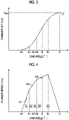
- Fig. 3 is a graph illustrating an example of a plunger lift amount at each cam angle.
- Fig. 4 is a graph illustrating an example of a plunger speed at each cam angle.
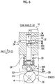
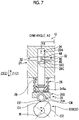
- Figs. 5 to 9 are schematic views illustrating a position of the plunger at each cam angle.
- a horizontal axis in Fig. 3 indicates a cam angle of the cam 22, and a vertical axis indicates the plunger lift amount, that is, the movement amount of the plunger 28 in the Z-direction at each cam angle.
- the cam angle indicates a rotation angle when the cam 22 rotates in the R-direction, and has any value from 0° to 360°.
- Fig. 4 is a time derivative of the graph in Fig. 3 . More specifically, the horizontal axis in Fig.
- the cam angle indicates the cam angle when the cam 22 rotates at the constant speed.
- the vertical axis in Fig. 4 indicates the plunger speed at each cam, that is, the speed of the plunger 28 in the Z-direction at each cam angle when it is assumed that the cam 22 rotates at the constant speed.
- the cam angle is continuously changed from a cam angle A0 toward a cam angle C via cam angles A1, A2, A3, B, and B1.
- the first cam surface C1 is a portion of the cam surface C extending from the cam angle A0 to the cam angle A1.
- the second cam surface C2 is a portion of the cam surface C extending from the cam angle A1 to the cam angle A3.
- the cam surface CB is a portion of the cam surface C extending from the cam angle A3 to the cam angle C.
- the cam surface CC is a portion of the cam surface C after the cam angle C.
- the fuel injection pump 10 moves the plunger 28 in the Z1-direction during a pre-stroke period D1, but does not increase the pressure of the fuel F in the fuel supply chamber 34.
- the pre-stroke period D1 is a period until the pressure of the fuel F in the fuel supply chamber 34 starts to increase. Furthermore, the pre-stroke period D1 indicates a period until the plunger 28 reaches a pressure increasing start position during a period in which the cam 22 rotates.
- the pressure increasing start position indicates a state where the plunger 28 reaches a position illustrated in Fig. 5 , and is a position where the plunger 28 starts to increase the pressure of the fuel F in the fuel supply chamber 34.
- Fig. 2 illustrates positions of the cam 22 and the plunger 28 at a time when the pre-stroke period D1 starts.
- the tip portion 28A of the plunger 28 is located on a side in the Z2-direction from the fuel supply path 32. Therefore, until the time when the pre-stroke period D1 starts, the fuel supply chamber 34 and the fuel supply path 32 communicate with each other, and the fuel F is supplied into the fuel supply chamber 34. For example, the fuel F is supplied from the fuel supply path 32 to the fuel supply chamber 34 during a period in which the plunger 28 moves in the Z2-direction.
- Fig. 2 illustrates a state where the cam 22 reaches the cam angle A0. That is, the pre-stroke period D1 starts at a time when the cam 22 reaches the cam angle A0. At the time when the cam 22 reaches the cam angle A0, a boundary position between the cam surface C0 and the first cam surface C1 is in a state of being in contact with the roller 26A. In other words, when the cam 22 reaches the cam angle A0, the base end portion 28B of the plunger 28 is in a state of being located on the boundary position between the cam surface C0 and the first cam surface C1. Therefore, the plunger 28 is located on the cam surface C0 during the period until the cam 22 reaches the cam angle A0. As illustrated in Fig.
- the lift amount of the cam 22 when the cam 22 reaches the cam angle A0 is set to 0.
- the cam surface C0 has a shape so that the lift amount of the plunger 28 is constant (here, the lift amount remains 0) when the cam 22 rotates.
- the cam surface C0 has a shape so that a distance from a rotation center O to each position along the R-direction on the cam surface C0 is constant. Therefore, during a period in which the plunger 28 is located on the cam surface C0, that is, until a time when the period is switched to the pre-stroke period D1, the lift amount of the plunger 28 and the speed in the Z-direction are 0 as illustrated in Figs. 3 and 4 .
- the shape of the cam surface C0 is not limited thereto, and may be determined in any way.
- Fig. 5 illustrates positions of the cam 22 and the plunger 28 at a time when the plunger 28 reaches the pressure increasing start position.
- the pressure increasing start position is a position where the plunger 28 starts to increase the pressure of the fuel F in the fuel supply chamber 34, and is a position where the plunger 28 starts to close the fuel supply path 32.
- the tip portion 28A of the plunger 28 is located at the same position as the end portion on a side in the Z1-direction of the fuel supply path 32 in the Z-direction, and the plunger 28 closes the fuel supply path 32.
- the pre-stroke period D1 ends at the time when the plunger 28 reaches the pressure increasing start position.
- the plunger 28 does not close the fuel supply path 32. Therefore, the fuel supply chamber 34 and the fuel supply path 32 communicate with each other. Therefore, during the pre-stroke period D1, even when the plunger 28 is lifted to move in the Z1-direction, the pressure of the fuel F in the fuel supply chamber 34 is not increased.
- the fuel supply chamber 34 and the fuel supply path 32 are cut off. Therefore, when the plunger 28 is lifted to move in the Z1-direction, the pressure of the fuel F in the fuel supply chamber 34 is increased by compression.
- the cam 22 reaches the cam angle A1 illustrated in Figs. 3 and 4 . That is, the cam surface C of the cam 22 is set so that the plunger 28 reaches the pressure increasing start position at a time when the cam angle is the cam angle A1. Therefore, in the present embodiment, a period from the cam angle A0 to the cam angle A1 is the pre-stroke period D1.
- a boundary position between the first cam surface C1 and the second cam surface C2 is located at a position in contact with the roller 26A.
- the base end portion 28B of the plunger 28 is in a state of being located on the boundary position between the first cam surface C1 and the second cam surface C2.
- the plunger 28 is located on the first cam surface C1 from the cam angle A0 to the cam angle A1, that is, during the pre-stroke period D1.
- the first cam surface C1 has a shape so that the lift amount of the plunger 28 increases toward the R-direction when the cam 22 rotates.
- the first cam surface C1 has a shape so that a distance from the rotation center 0 to the first cam surface C1 is lengthened toward the R-direction.
- the first cam surface C1 has a shape so that the speed of the plunger 28 in the Z1-direction increases toward the R-direction when the cam 22 rotates at a constant speed. Therefore, the lift amount of the plunger 28 and the speed in the Z-direction during the pre-stroke period D1 increase as the cam angle advances, as illustrated in Figs. 3 and 4 .
- the increase rate of the speed of the plunger 28 in the Z1-direction when the cam 22 rotates at the constant speed while the plunger 28 is located on the first cam surface C1 will be referred to as a first increase rate K1 (refer to Fig. 4 ) .
- the first increase rate K1 is an increase rate of the speed of the plunger 28 in the Z1-direction as the cam 22 rotates in the R-direction (with the lapse of time) during the pre-stroke period D1.
- the first cam surface C1 is set so that the first increase rate K1 is higher than a second increase rate K2 (to be described later) on the second cam surface C2.
- the first increase rate K1 here indicates an increase rate of the speed of the plunger 28 in the Z1-direction when the cam 22 rotates at the constant speed for a unit time, and the same applies to the following increase rate (second increase rate K2).
- the first cam surface C1 has a shape so that the increase rate of the distance from the rotation center 0 to the first cam surface C1 increases toward the R-direction.
- the increase rate of the distance from the rotation center O to the first cam surface C1 indicates an increase rate of the distance separated by a unit distance from the predetermined position in the R-direction from the rotation center O to a position of the first cam surface C1, with respect to the distance from the rotation center O to the predetermined position of the first cam surface C1. The same applies to the following increase rate of the distance.
- the first cam surface C1 is a portion of the cam surface C on which the plunger 28 is located during the pre-stroke period D1, and has a shape so that the increase rate of the speed of the plunger in the Z1-direction when the cam 22 rotates at the constant speed is the first increase rate K1.
- the first cam surface C1 has a recessed curved surface shape recessed toward the rotation center O of the cam 22.
- the first cam surface C1 is not limited to the recessed curved surface shape, and may have any shape such as a protruding curved surface shape protruding from the rotation center.
- the fuel injection pump 10 increases the pressure of the fuel F in the fuel supply chamber 34 while moving the plunger 28 in the Z1-direction during a pressure increasing period D2.
- the pressure increasing period D2 is a period after the plunger 28 starts to increase the pressure of the fuel F in the fuel supply chamber 34, and is a period until the fuel F starts to be injected from the injector 14 into the combustion chamber 16.
- the pressure increasing period D2 indicates a period after the plunger 28 reaches the pressure increasing start position during the period in which the cam 22 rotates, and more specifically, indicates a period in which the plunger 28 is located from the pressure increasing start position to an injection position.
- the injection position indicates a position of the plunger 28 at a time when the injector 14 starts to inject the fuel F into the combustion chamber 16.
- the pressure increasing period D2 is a period after the plunger 28 reaches the pressure increasing start position. Therefore, the pressure increasing period D2 indicates a time when the state in Fig. 5 is switched from the pre-stroke period D1 to the pressure increasing period D2.
- Fig. 6 illustrates a time when the pressure increasing period D2 ends, in other words, a time when the plunger 28 reaches the injection position.
- the tip portion 28A of the plunger 28 is located on a side in the Z1-direction from the end portion of the fuel supply path 32 on a side in the Z1-direction.
- the second lead 46 of the plunger 28 is located on a side in the Z2-direction from the fuel supply path 32, and does not communicate with the fuel supply path 32. Therefore, the plunger 28 continues to close the fuel supply path 32 during the pressure increasing period D2, that is, from the pressure increasing start position to the injection position. Therefore, during the pressure increasing period D2, the fuel F in the fuel supply chamber 34 is compressed, and the pressure is increased as the plunger 28 moves in the Z1-direction. Then, at a time when the plunger 28 reaches the injection position, the nozzle 64 of the injector 14 is opened by the pressure of the fuel F, and the fuel F starts to be injected from the injector 14 into the combustion chamber 16.
- the injection position of the plunger 28 may be set in accordance with a valve opening pressure of the injector 14 or a position of the fuel supply path 32 in the Z-direction.
- a period from the cam angle A1 to the cam angle A2 is the pressure increasing period D2.
- the cam 22 is located at a position where the second cam surface C2 is in contact with the roller 26A.
- the base end portion 28B of the plunger 28 is in a state of being located on the second cam surface C2.
- the plunger 28 is located on the second cam surface C2 from the cam angle A1 to the cam angle A2, that is, during the pressure increasing period D2.
- the second cam surface C2 has a shape so that the lift amount of the plunger 28 increases toward the R-direction when the cam 22 rotates.
- the second cam surface C2 has a shape so that a distance from the rotation center O to the second cam surface C2 is lengthened toward the R-direction.
- the second cam surface C2 has a shape so that the speed of the plunger 28 in the Z1-direction increases toward the R-direction when the cam 22 rotates at the constant speed. Therefore, the lift amount of the plunger 28 and the speed in the Z-direction during the pressure increasing period D2 increase as the cam angle advances, as illustrated in Figs. 3 and 4 .
- the second increase rate K2 is the increase rate of the speed of the plunger 28 in the Z1-direction as the cam 22 rotates in the R-direction (with the lapse of time) during the pressure increasing period D2.
- the second cam surface C2 is set so that the second increase rate K2 is lower than the first increase rate K1 on the first cam surface C1.
- the second cam surface C2 has a shape so that the increase rate of the distance from the rotation center O to the second cam surface C2 increases toward the R-direction. Then, the increase rate of the distance from the rotation center O to the second cam surface C2 is lower than the increase rate of the distance from the rotation center O to the first cam surface C1.
- the second cam surface C2 is a portion of the cam surface C on which the plunger 28 is located during the pressure increasing period D2, and has a shape so that the increase rate of the speed of the plunger in the Z1-direction when the cam 22 rotates at the constant speed is the second increase rate K2.
- the second cam surface C2 has a protruding curved surface shape protruding from the rotation center O of the cam 22.
- the first cam surface C1 is not limited to the protruding curved surface shape, and may have any shape.
- the first cam surface C1 and the second cam surface C2 are provided so that the plunger 28 reaches a portion on the boundary position (that is, to reach cam angle A1) between the first cam surface C1 and the second cam surface C2 when the plunger 28 reaches the pressure increasing start position.
- the first cam surface C1 and the second cam surface C2 are set so that the first increase rate K1 is switched to the second increase rate K2 when the plunger 28 reaches the pressure increasing start position.
- the time when the plunger 28 reaches the pressure increasing start position and the time when the plunger 28 reaches the portion on the boundary position between the first cam surface C1 and the second cam surface C2 may be different from each other.
- the time when the plunger 28 reaches the pressure increasing start position may be slightly later or slightly earlier than the time when the plunger 28 reaches the portion on the boundary position between the first cam surface C1 and the second cam surface C2.
- the fuel injection pump 10 injects the fuel F in the fuel supply chamber 34 from the injector 14 while moving the plunger 28 in the Z1-direction during an injection period D3.
- the injection period D3 is a period in which the fuel F is injected. Furthermore, the injection period D3 indicates a period after the plunger 28 reaches the injection position during the period in which the cam 22 rotates. In the present embodiment, the injection period D3 is a period in which the plunger 28 is located from the injection position to a post-injection position.
- the post-injection position indicates a state where the plunger 28 is located at a position illustrated in Fig. 7 . As will be described later, the post-injection position indicates a position when the plunger 28 reaches the portion on the boundary position between the second cam surface C2 and the cam surface CB.
- the injection period D3 is a period after the plunger 28 reaches the injection position. Therefore, the injection period D3 indicates a time when the state in Fig. 6 illustrating the injection position is switched from the pressure increasing period D2 to the injection period D3.
- Fig. 7 illustrates a time when the injection period D3 ends, in other words, a time when the plunger 28 reaches the post-injection position.
- the tip portion 28A of the plunger 28 is located on a side in the Z1-direction from the end portion of the fuel supply path 32 on a side in the Z1-direction
- the second lead 46 of the plunger 28 is located on a side in the Z2-direction from the fuel supply path 32, and does not communicate with the fuel supply path 32.
- the plunger 28 continues to close the fuel supply path 32 while moving in the Z1-direction during the injection period D3, that is, during a period from the injection position to the post-injection position.
- the fuel F is injected from the injector 14 into the combustion chamber 16.
- the cam 22 reaches the cam angle A3 at a time when the plunger 28 reaches the post-injection position. That is, in the present embodiment, a period from the cam angle A2 to the cam angle A3 is the injection period D3.
- the boundary position between the second cam surface C2 and the cam surface CB is a position in contact with the roller 26A.
- the base end portion 28B of the plunger 28 is in a state of being located on the boundary position between the second cam surface C2 and the cam surface CB.
- the plunger 28 is located on the second cam surface C2 during the injection period D3, subsequently to the pressure increasing period D2. Therefore, even during the injection period D3, the plunger 28 moves toward a side in the Z1-direction while the speed is increased at the second increase rate K2, subsequently to the pressure increasing period D2.
- the fuel injection pump 10 injects the fuel F in the fuel supply chamber 34 from the injector 14 while moving the plunger 28 in the Z1-direction during a post-injection period DB.
- the post-injection period DB is a period after the plunger 28 reaches the injection position, and is a period in which the fuel F is injected subsequently to the injection period D3.
- the post-injection period DB is different from the injection period D3 in that the increase rate of the speed of the plunger 28 is switched to an increase rate KB.
- the post-injection period DB indicates a period after the plunger 28 reaches the post-injection position during a period in which the cam 22 rotates.
- the post-injection period DB is a period in which the plunger 28 is located from the post-injection position to an injection end position.
- the injection end position indicates a state where the plunger 28 is located at a position illustrated in Fig. 8 , and indicates a position of the plunger 28 at a time when the injector 14 ends the injection of the fuel F into the combustion chamber 16.
- the post-injection period DB is a period after the plunger 28 reaches the post-injection position. Therefore, the post-injection period DB indicates a time when the state in Fig. 7 is switched from the injection period D3 to the post-injection period DB.
- Fig. 8 illustrates a time when the post-injection period DB ends. In other words, Fig. 8 illustrates a time when the plunger 28 reaches the injection end position.
- the injection end position is the position of the plunger 28 where the injection of the fuel F ends, and is a position where the plunger 28 ends closing of the fuel supply path 32.
- the second lead 46 of the plunger 28 is located at the same position as the fuel supply path 32 in the Z-direction, and the second lead 46 and the fuel supply path 32 communicate with each other.
- the fuel supply chamber 34 communicates with the fuel supply path 32 via the first lead 44 and the second lead 46, and the fuel in the fuel supply chamber 34 can move to the fuel supply path 32 side. Therefore, the pressure of the fuel F in the fuel supply chamber 34 is decreased, the nozzle 64 of the injector 14 is closed, and the injection of the fuel F ends.
- the cam 22 reaches a cam angle B. That is, in the present embodiment, a period from the cam angle A3 to the cam angle B is the post-injection period DB. As illustrated in Figs. 7 and 8 , from the cam angle A3 to the cam angle B, the cam 22 is located at a position where the cam surface CB is in contact with the roller 26A. In other words, from the cam angle A3 to the cam angle B, the base end portion 28B of the plunger 28 is in a state of being located on the cam surface CB.
- the cam surface CB includes a cam surface CB1 which is a portion extending from the cam angle A3 to the cam angle B1 via the cam angle B, and a cam surface CB2 which is a portion extending from the cam angle B1 to the cam angle C.
- the plunger 28 is located on the cam surface CB1 during the post-injection period DB.
- the cam surface CB1 has a shape so that the lift amount of the plunger 28 increases toward the R-direction when the cam 22 rotates. In other words, the cam surface CB1 has a shape so that a distance from the rotation center O to the cam surface CB is lengthened toward the R-direction.
- the cam surface CB1 has a shape so that the speed of the plunger 28 in the Z1-direction increases toward the R-direction when the cam 22 rotates at the constant speed. Therefore, the lift amount of the plunger 28 and the speed in the Z-direction during the post-injection period DB increase as the cam angle advances, as illustrated in Figs. 3 and 4 .
- the increase rate of the speed of the plunger 28 in the Z1-direction when the cam 22 rotates at the constant speed while the plunger 28 is located on the cam surface CB1 will be referred to as an increase rate KB (refer to Fig. 4 ).
- the increase rate KB is an increase rate of the speed of the plunger 28 in the Z1-direction as the cam 22 rotates in the R-direction (with the lapse of time) during the post-injection period DB.
- the cam surface CB1 is set so that the increase rate KB is lower than the first increase rate K1 on the first cam surface C1.
- the cam surface CB1 is set so that the increase rate KB is lower than the second increase rate K2 on the second cam surface C2.
- the cam surface CB1 has a shape so that the increase rate of the distance from the rotation center O to the cam surface CB1 increases toward the R-direction.
- the increase rate of the distance from the rotation center O to the second cam surface C2 is lower than the increase rate of the distance from the rotation center O to the first cam surface C1.
- the increase rate of the distance from the rotation center O to the second cam surface C2 is lower than the increase rate of the distance to the second cam surface C2.
- the cam surface CB1 of the cam surface CB is a portion of the cam surface C where the plunger 28 is located during the post-injection period DB, and has a shape so that the increase rate of the speed of the plunger in the Z1-direction when the cam 22 rotates at the constant speed is a third increase rate K3.
- the cam surface CB has a protruding curved surface shape protruding from the rotation center O of the cam 22.
- the cam surface CB is not limited to the protruding curved surface shape, and may have any shape.
- the injection period D3 in a preceding period and the post-injection period DB in a post period are provided as an effective injection period for injecting the fuel F.
- the increase rate of the speed of the plunger 28 in the post-injection period DB is set to be smaller than the increase rate of the speed of the plunger 28 in the injection period D3. In this manner, it is possible to stabilize an injection amount.
- the fuel injection pump 10 is not limited to a case where the injection period D3 and the post-injection period DB are provided. For example, only the injection period D3 out of the injection period D3 and the post-injection period DB may be provided.
- the second cam surface C2 is formed in the portion of the cam surface CB1. Then, the speed of the plunger 28 increases at the second increase rate K2 over the whole effective injection period, in other words, until the plunger 28 reaches the injection end position.
- the fuel injection pump 10 raises the plunger 28 to a top dead center while reducing the speed of the plunger 28 during a post period DC.
- the post period DC is a period subsequent to the post-injection period DB, that is, a period after the injection ends. During the post period DC, the pressure of the fuel F is not increased or the fuel F is not injected.
- the post period DC is a period in which the cam 22 reaches the cam angle C from the cam angle B via the cam angle B1.
- the boundary position between the cam surface CB1 and the cam surface CB2 is a position in contact with the roller 26A (not illustrated).
- the base end portion 28B of the plunger 28 is in a state of being located on the boundary position between the cam surface CB1 and the cam surface CB2. Therefore, in the post period DC, during a period in which the cam 22 reaches the cam angle B1 from the cam angle B, the plunger 28 is located on the cam surface CB1, subsequently to the post-injection period DB.
- the plunger 28 moves toward a side in the Z1-direction while increasing the speed at the increase rate KB, subsequently to the post-injection period DB.
- the fuel supply chamber 34 and the fuel supply path 32 communicate with each other via the second lead 46, and the fuel F is not injected.
- Fig. 9 illustrates a case where the cam 22 reaches the cam angle C.
- the boundary position between the cam surface CB (cam surface CB2) and the cam surface CC is a position in contact with the roller 26A (not illustrated).
- the base end portion 28B of the plunger 28 is in a state of being located on the boundary position between the cam surface CB2 and the cam surface CC. Therefore, in the post period DC, the plunger 28 is located on the cam surface CB2 during a period in which the cam 22 reaches the cam angle C from the cam angle B1.
- the cam surface CB2 has a shape so that the lift amount of the plunger 28 increases toward the R-direction when the cam 22 rotates.
- the cam surface CB2 has a shape so that a distance from the rotation center O to the cam surface CB2 is lengthened toward the R-direction.
- the cam surface CB2 has a shape so that the speed of the plunger 28 in the Z1-direction decreases toward the R-direction when the cam 22 rotates at the constant speed. Therefore, in the post period DC, during a period in which the cam 22 reaches the cam angle C from the cam angle B1, the plunger 28 moves in the Z1-direction while reducing the speed, as illustrated in Figs. 3 and 4 .
- the plunger 28 reaches the top dead center at the cam angle C, and the lift amount becomes a maximum lift L MAX (refer to Fig. 3 ). Thereafter, when the rotation of the cam 22 continues, the plunger 28 is located on the cam surface CC, and moves in the Z2-direction in accordance with the shape of the cam surface CC.
- the fuel injection pump 10 switches among the pre-stroke period D1, pressure increasing period D2, the injection period D3, the post-injection period DB, and the post period DC in this order as the cam 22 rotates at the constant speed.
- the plunger 28 gradually increases the speed in accordance with the first increase rate K1 while rising in the Z1-direction.
- the plunger 28 continues to ascend in the Z1-direction.
- the plunger 28 increases the pressure of the fuel F
- the plunger 28 gradually increases the speed in accordance with the second increase rate K2. Then, when the pressure increasing period D2 is switched to the injection period D3, the plunger 28 continues to ascend in the Z1-direction.
- the plunger 28 While the fuel F is injected, the plunger 28 further increases the speed in a state where the second increase rate K2 is maintained.
- the injection period D3 is switched to the post-injection period DB, the plunger 28 continues to ascend in the Z1-direction.
- the plunger 28 gradually increases the speed in accordance with the increase rate KB.
- the post-injection period DB is switched to the post period DC, the injection of the fuel F ends, and the plunger 28 continues to ascend in the Z1-direction. After reaching the maximum lift L MAX , the plunger 28 descends in the Z2-direction.
- the pressure of the fuel to be supplied needs to be increased to improve engine performance and gas exhausting.
- it is effective to increase the speed of the plunger.
- the speed of the plunger can be increased by designing a cam profile.
- the maximum lift amount of the cam may be increased by uniformly increasing the plunger speed.
- a size of the pump may be increased in some cases.
- an effective injection period of the fuel may be shortened, thereby causing a possibility that the supply amount of the fuel may decrease.
- the cam profile is set so that the speed increase rate (first increase rate K1) of the plunger 28 during the pre-stroke period D1 before the pressure of the fuel F starts to increase is higher than the speed increase rate (second increase rate K2) of the plunger 28 during the pressure increasing period D2 after the pressure of the fuel F starts to increase. Therefore, according to the fuel injection pump 10 in the present embodiment, the plunger speed is increased during the pre-stroke period D1 before the pressure of the fuel F starts to increase. In this manner, a sufficient plunger speed can be obtained when the fuel F is injected. Therefore, the pressure of the fuel F can be properly increased. In addition, the speed increase rate can be gentle during the pressure increasing period D2. In this manner, while an increase in the maximum lift amount of the cam can be minimized, it is possible to reduce a possibility that the effective injection period may be shortened.
- the cam 22 is used for the fuel injection pump 10 that increases the pressure of the fuel F supplied into the fuel supply chamber 34 by moving the plunger 28 in the Z-direction (axial direction).
- the cam 22 includes the first cam surface C1 and the second cam surface C2.
- the first cam surface C1 has a shape so that the increase rate of the speed of the plunger 28 in the Z1-direction when the cam 22 rotates at the constant speed during the pre-stroke period D1 until the plunger 28 increases the pressure of the fuel F in the fuel supply chamber 34 is the first increase rate is K1.
- the second cam surface C2 has a shape so that the increase rate of the speed the plunger 28 in the Z1-direction when the cam 22 rotates at the constant speed during the pressure increasing period D2 after the plunger 28 starts increasing the pressure of the fuel F in the fuel supply chamber 34 is the second increase rate K2. Then, the first increase rate K1 is set to be higher than the second increase rate K2.
- the cam profile is set so that the first increase rate K1 is higher than the second increase rate K2. Therefore, while the pressure of the fuel F is properly increased by increasing the plunger speed during the pre-stroke period D1, it is possible to reduce an increase in the maximum lift amount of the cam 22 and degradation in fuel injection capacity.
- the cam 22 according to the present embodiment can reduce an increase in the size or the weight of the fuel injection pump 10 by minimizing an increase in the maximum lift amount of the cam 22.
- the cam 22 according to the present embodiment is provided with the first cam surface C1 and the second cam surface C2 so that the first increase rate K1 is switched to the second increase rate K2 when the plunger 28 reaches the pressure increasing start position where the pressure of the fuel F in the fuel supply chamber 34 starts to increase.
- the cam 22 according to the present embodiment switches the speed increase rate of the plunger 28 to the second increase rate K2 at a time when the pressure of the fuel F starts to increase. Therefore, while the pressure of the fuel is properly increased, it is possible to reduce an increase in the maximum lift amount of the cam 22 and degradation in the fuel injection capacity.
- the cam 22 according to the present embodiment further includes the cam surface CB1.
- the cam surface CB1 has a shape so that the increase rate of the speed of the plunger 28 in the Z1-direction when the cam 22 rotates at the constant speed during the post-injection period DB after the plunger 28 reaches the injection position is the increase rate is KB lower than the second increase rate K2.
- the cam 22 according to the present embodiment can perform stable fuel injection by minimizing the speed increase rate of the plunger 28 during the post-injection period DB.
- first cam surface C1 has a recessed curved surface shape recessed toward the rotation center O of the cam 22
- second cam surface C2 has a protruding curved surface shape protruding from the rotation center O of the cam 22.
- the first cam surface C1 and the second cam surface C2 have the shape in this way. Accordingly, the cam 22 has a shape so that the first increase rate K1 and the second increase rate K2 can be properly achieved.
- the fuel injection pump 10 includes the cam 22, the plunger 28 provided on the cam surface C of the cam 22 and moving in the Z-direction as the cam 22 rotates, and the fuel supply chamber 34 accommodating the plunger 28. Since the fuel injection pump 10 includes the cam 22 as described above, while the pressure of the fuel F is properly increased, it is possible to reduce an increase in the maximum lift amount of the cam 22 and degradation in the fuel injection capacity.
- the fuel injection pump 10 according to the present embodiment can reduce an increase in the size or the weight of the fuel injection pump 10 by minimizing an increase in the maximum lift amount of the cam 22.
- the fuel injection pump 10 is provided with a maximum plunger ascending acceleration section during the pre-stroke period D1 before the pressure of the fuel F starts to increase, that is, ascending acceleration of the plunger 28 is maximized during the pre-stroke period D1 of the all periods. Therefore, it is possible to reduce an increase in the acting pressure and sliding seizure or wear caused by the increased speed when the plunger 28 slides.
- the engine 100 according to the present embodiment includes the fuel injection pump 10, the injector 14 to which the fuel F to be injected from the fuel injection pump 10 is supplied, and the combustion chamber 16 to which the fuel F injected from the injector 14 is supplied. Since the engine 100 according to the present embodiment includes the cam 22 as described above, while the pressure of the fuel F is properly increased, it is possible to reduce an increase in the maximum lift amount of the cam 22 and degradation in the fuel injection capacity. The engine 100 according to the present embodiment can reduce an increase in the size or the weight of the fuel injection pump 10 by minimizing an increase in the maximum lift amount of the cam 22.
- the cam 22 according to the modification example is different from the cam 22 of the above-described embodiment in that the cam 22 according to the modification example includes a third cam surface C3.
- locations having configurations common to those of the above-described embodiment will be omitted in the description.
- Fig. 10 is a schematic view of a fuel injection pump according to the modification example
- Fig. 11 is a graph illustrating an example of a plunger speed at each cam angle in the modification example.
- the cam surface C0, the first cam surface C1, the second cam surface C2, the third cam surface C3, the cam surface CB, and the cam surface CC are formed as the cam surface C.
- the second cam surface C2 in the modification example is formed from the cam angle A1 to the cam angle A2 of the cam surface C
- the third cam surface C3 is formed from the cam angle A2 to the cam angle A3 of the cam surface C.
- the third cam surface C3 has a shape so that the lift amount of the plunger 28 increases toward the R-direction when the cam 22 rotates.
- the third cam surface C3 has a shape so that a distance from the rotation center O to the third cam surface C3 is lengthened toward the R-direction.
- the third cam surface C3 has a shape so that the speed of the plunger 28 in the Z1-direction increases toward the R-direction when the cam 22 rotates at the constant speed.
- the increase rate of the speed of the plunger 28 in the Z1-direction when the cam 22 rotates at the constant speed while the plunger 28 is located on the third cam surface C3 will be referred to as a third increase rate K3.
- the third increase rate K3 is an increase rate of the speed of the plunger 28 in the Z1-direction as the cam 22 rotates in the R-direction (with the lapse of time) during the injection period D3.
- the third cam surface C3 is set so that the third increase rate K3 is lower than the first increase rate K1 on the first cam surface C1, more specifically, so that the third increase rate K3 is lower than the second increase rate K2 on the second cam surface C2.
- the third cam surface C3 has a shape so that the increase rate of the distance from the rotation center O to the third cam surface C3 increases toward the R-direction.
- the increase rate of the distance from the rotation center O to the third cam surface C3 is lower than the increase rate of the distance from the rotation center O to the first cam surface C1. Furthermore, the increase rate of the distance from the rotation center O to the third cam surface C3 is lower than the increase rate of the distance from the rotation center O to the second cam surface C2.
- the plunger 28 is located on the second cam surface C2 during the pressure increasing period D2 from the cam angle A1 to the cam angle A2. Then, at the cam angle A2 in which the pressure increasing period D2 is switched to the injection period D3, the plunger 28 is located on the boundary position between the second cam surface C2 and the third cam surface C3, and the plunger 28 is located on the third cam surface C3 during the injection period D3 from the cam angle A2 to the cam angle A3. Therefore, in the modification example, during the pressure increasing period D2, the plunger 28 continues to ascend in the Z1-direction. While the plunger 28 increases the pressure of the fuel F, the plunger 28 gradually increases the speed in accordance with the second increase rate K2. Then, when the pressure increasing period D2 is switched to the injection period D3, the plunger 28 continues to ascend in the Z1-direction. While the fuel F is injected, the plunger 28 gradually increases the speed in accordance with the third increase rate K3.
- the cam 22 further includes the third cam surface C3, and the pressure increasing period D2 is a period in which the plunger 28 is located from the pressure increasing start position to the injection position where the fuel F is injected.
- the third cam surface C3 has a shape so that the increase rate of the speed of the plunger 28 in the Z1-direction when the cam 22 rotates at the constant speed during the injection period D3 after the plunger 28 reaches the injection position is the third increase rate K3.
- the first increase rate K1 is set to be higher than the third increase rate K3.
- the first increase rate K1 during the pre-stroke period D1 is set to be higher than the third increase rate K3 during the injection period D3. In this manner, the plunger speed can be sufficiently increased until the injection, and the pressure of the fuel F can be properly increased.
- the second increase rate K2 is set to be higher than the third increase rate K3. That is, in the cam 22, the speed increase rate of the plunger 28 is increased in the order of the injection period D3, the pressure increasing period D2, and the pre-stroke period D1. Therefore, according to the cam 22, the plunger speed can be sufficiently increased until the injection period D3, and the pressure of the fuel F can be properly increased.
- the speed increase rate during the pressure increasing period D2 is set to be lower than that during the pre-stroke period D1. In this manner, it is possible to reduce a possibility that a load on the plunger 28 may be excessively higher during the pressure increasing period D2 in which the fuel pressure acts on the plunger 28.
- the embodiments of the present invention have been described. However, the embodiments are not limited by contents of the embodiments.
- the above-described configuration elements include those which can be easily assumed by those skilled in the art, those which are substantially the same, and those which have a so-called equal range. Furthermore, the above-described configuration elements can properly be combined with each other. In addition, various omissions, replacements, or modifications of the configuration elements can be made within the scope not departing from the concept of the above-described embodiments.
Landscapes
- Engineering & Computer Science (AREA)
- General Engineering & Computer Science (AREA)
- Mechanical Engineering (AREA)
- Chemical & Material Sciences (AREA)
- Combustion & Propulsion (AREA)
- Fuel-Injection Apparatus (AREA)
- Gears, Cams (AREA)
Abstract
Description
- The present invention relates to a cam, a fuel injection pump, and an engine.
- A fuel injection pump for a diesel engine converts a rotational motion of a camshaft into a reciprocating motion by using a plunger. The fuel injection pump increases a pressure of a fuel in a fuel supply chamber and supplies the fuel to an injector by using the reciprocating motion of the plunger, and injects the pressure-increased fuel from the injector into a combustion chamber of the engine. As the fuel injection pump configured in this way, for example, as disclosed in PTL 1, a so-called mechanical fuel injection pump is known which opens a nozzle to inject the fuel by using a difference between a nozzle valve opening force generated by the pressure-increased fuel and a valve closing force generated by a spring on a nozzle back surface.
- [PTL 1]
Japanese Unexamined Patent Application Publication No. 4-191420 - In the mechanical fuel injection pump configured in this way, the pressure of the fuel to be injected needs to be increased to improve engine performance and gas exhausting. In order to increase the pressure of the fuel, it is effective to increase a speed of a plunger. A speed in a pumping process of the plunger can be increased by designing a cam profile. However, there is room for improvement in setting the cam profile to increase a plunger speed. For example, in order to increase the plunger speed, it becomes necessary to set the cam profile to increase a maximum lift amount of a cam. Consequently, in some cases, a size of the pump may increase. In addition, when the cam profile is set to increase the plunger speed while the maximum lift amount of the cam is maintained, an effective injection period of the fuel is shortened, thereby causing a possibility that fuel injection capacity may be degraded.
- The present disclosure is made to solve the above-described problems, and an object of the present disclosure is to provide a cam, a fuel injection pump, and an engine which can increase an injection pressure of a fuel while reducing an increase in a maximum lift amount of a cam and degradation in fuel injection capacity.
- According to the present disclosure, in order to solve the above-described problems and achieve the object, there is provided a cam used for a fuel injection pump that increases a pressure of a fuel supplied into a fuel supply chamber by moving a plunger in an axial direction. The cam includes a first cam surface in which an increase rate of a speed of the plunger in the axial direction when the cam rotates at a constant speed is a first increase rate during a pre-stroke period until the plunger increases the pressure of the fuel in the fuel supply chamber, and a second cam surface in which the increase rate of the speed of the plunger in the axial direction when the cam rotates at the constant speed is a second increase rate during a pressure increasing period which is a period after the plunger starts to increase the pressure of the fuel in the fuel supply chamber. The first increase rate is set to be higher than the second increase rate.
- According to the present disclosure, in order to solve the above-described problems and achieve the object, there is provided a fuel injection pump including the cam, a plunger provided on a cam surface of the cam, and moving in the axial direction in response to rotation of the cam, and a fuel supply chamber that accommodates the plunger.
- According to the present disclosure, in order to solve the above-described problems and achieve the object, there is provided an engine including the fuel injection pump, an injector to which the fuel is supplied from the fuel injection pump, and a combustion chamber to which the fuel injected from the injector is supplied.
- According to the present invention, it is possible to increase a fuel injection pressure while reducing an increase in a maximum lift amount of the cam and degradation in fuel injection capacity.
-
-
Fig. 1 is a schematic view of an engine according to the present embodiment. -
Fig. 2 is a schematic view of a fuel injection system according to the present embodiment. -
Fig. 3 is a graph illustrating an example of a plunger lift amount at each cam angle. -
Fig. 4 is a graph illustrating an example of a plunger speed at each cam angle. -
Fig. 5 is a schematic view illustrating a position of a plunger at each cam angle. -
Fig. 6 is a schematic view illustrating a position of the plunger at each cam angle. -
Fig. 7 is a schematic view illustrating a position of the plunger at each cam angle. -
Fig. 8 is a schematic view illustrating a position of the plunger at each cam angle. -
Fig. 9 is a schematic view illustrating a position of the plunger at each cam angle. -
Fig. 10 is a schematic view of a fuel injection pump according to a modification example. -
Fig. 11 is a graph illustrating an example of a plunger speed at each cam angle in a modification example. Description of Embodiments - Hereinafter, a preferred embodiment of the present invention will be described in detail with reference to the accompanying drawings. The present invention is not limited by the embodiment. In a case where there are a plurality of the embodiments, the present invention also includes a configuration adopted by combining the respective embodiments with each other.
-
Fig. 1 is a schematic view of an engine according to the present embodiment. As illustrated inFig. 1 , anengine 100 according to the present embodiment includes a fuel injection system 1 and acombustion chamber 16. Theengine 100 injects a fuel F into thecombustion chamber 16 from the fuel injection system 1. Theengine 100 combusts the fuel F in thecombustion chamber 16 to operate and drive a drive unit such as a crankshaft (not illustrated). In the present embodiment, the fuel F is light oil, and theengine 100 is a diesel engine. However, the fuel F is not limited to the light oil, and may be any oil. For example, kerosene or heavy oil (heavy oil A) . Furthermore, theengine 100 according to the present embodiment is connected to a generator (not illustrated), and drives the generator so that the generator generates power. That is, theengine 100 according to the present embodiment is theengine 100 for power generation facilities. However, an application of theengine 100 is not limited to the power generation facilities, and may be an engine of a ship or a vehicle, for example. - The fuel injection system 1 is a system that injects the high-pressure fuel F into the
combustion chamber 16. The fuel injection system 1 includes afuel injection pump 10, apipe 12, and aninjector 14. In the present embodiment, the fuel injection system 1 is a fuel injection system that does not include a common rail. That is, thefuel injection pump 10 is a so-called mechanical fuel injection pump in which a nozzle of theinjector 14 is opened to inject the fuel F by using a difference between a nozzle valve opening force generated by the pressure-increased fuel F of theinjector 14 and a spring force on a nozzle back surface. - In the
fuel injection pump 10, acam 22 is provided in ahousing 20. Thecam 22 includes ashaft 22A serving as a shaft-shaped member extending in an X-direction, and acam portion 22B provided on an outer periphery of theshaft 22A. In the present embodiment, thecam 22 has a plurality of thecam portions 22B formed in the X-direction. Aplunger 28 is provided on thecam portion 22B via atappet 26. In the present embodiment, theplunger 28 is provided in each of thecam portions 22B via thetappet 26. Theplunger 28 is provided in thefuel injection pump 10 to extend in a Z-direction. The Z-direction which is an axial direction of theplunger 28 intersects with the X-direction which is an axial direction of theshaft 22A, and is orthogonal to the X-direction in the present embodiment. Hereinafter, one direction of directions along the Z-direction will be referred to as a Z1-direction, and the other direction, that is, a direction opposite to the Z1-direction will be referred to as a Z2-direction. The Z1-direction is a direction toward a tip side of theplunger 28, that is, a side away from thecam 22. The Z2-direction is a direction toward a base end side of theplunger 28, that is, thecam 22 side. Thefuel injection pump 10 may be provided with a governor G for adjusting an injection amount of the fuel F. For example, the governor G adjusts the injection amount of the fuel F by rotating theplunger 28 while theplunger 28 uses the Z-direction as a rotation center. - In this way, the
fuel injection pump 10 is a so-called row-type fuel injection pump in which a plurality of theplungers 28 are aligned in the X-direction. In an example inFig. 1 , sixcam portions 22B and sixplungers 28 are respectively provided in the X-direction. However, the number of thecam portions 22B and theplungers 28 is not limited thereto, and may be determined in any way. In addition, thefuel injection pump 10 is not limited to the row-type fuel injection pump, and may have a structure in which the plurality ofplungers 28 are provided on onecam portion 22B, for example. - The
pipe 12 is a pipe that connects thefuel injection pump 10 and theinjector 14. Thepipe 12 connects afuel supply chamber 34 of the fuel injection pump 10 (to be described later) and afuel supply chamber 60A of theinjector 14. The fuel F in thefuel supply chamber 34 is supplied to thefuel supply chamber 60A of theinjector 14 through thepipe 12. Theinjector 14 is connected to thecombustion chamber 16. Theinjector 14 supplies the fuel F supplied from thefuel injection pump 10 into thecombustion chamber 16. In the example inFig. 1 , for convenience of description, onepipe 12 and oneinjector 14 are provided for onefuel injection pump 10, but may be provided for each of theplungers 28. -
Fig. 2 is a schematic view of the fuel injection system according to the present embodiment.Fig. 2 includes a schematic sectional view of thefuel injection pump 10 when viewed in the X-direction and a schematic sectional view of theinjector 14. As illustrated inFig. 2 , thefuel injection pump 10 includes thecam 22, abarrel 24, thetappet 26, theplunger 28, and aspring portion 29. - The
cam 22 rotates in an R-direction while the X-direction is used as the rotation center. That is, the R-direction serving as a rotation direction of thecam 22 is a circumferential direction when the X-direction is a rotation axis, and the direction is set in advance. In an example inFig. 2 , the R-direction is counterclockwise, but the R-direction is not limited thereto. A cam surface C0, a first cam surface C1, a second cam surface C2, a cam surface CB, and a cam surface CC are formed on a surface of thecam portion 22B of thecam 22. The cam surface C0, the first cam surface C1, the second cam surface C2, the cam surface CB, and the cam surface CC are continuously provided in this order in the R-direction. Hereinafter, when the cam surface C0, the first cam surface C1, the second cam surface C2, the cam surface CB, and the cam surface CC are not distinguished, all of these will be referred to as a cam surface C. That is, the cam surface C indicates the surface of thecam portion 22B. Detailed description of the cam surface C will be described later. - The
barrel 24 is a member provided on a side in the Z1-direction of thecam 22. Thebarrel 24 internally has afuel supply path 32 and thefuel supply chamber 34. For example, thefuel supply path 32 is a flow path connected to a fuel tank of theengine 100, and to which the fuel F stored in the tank is supplied. Thefuel supply chamber 34 is a space formed to extend along the Z-direction, and is open on a side in the Z2-direction. Theplunger 28 is accommodated in thefuel supply chamber 34 to be slidable in the Z-direction. Thefuel supply chamber 34 is connected to thepipe 12. In addition, thefuel supply chamber 34 is formed to communicate with thefuel supply path 32. The fuel F is supplied into thefuel supply chamber 34 from thefuel supply path 32. - The
tappet 26 is provided on the cam surface C on a side in the Z1-direction of thecam portion 22B. Thetappet 26 includes aroller 26A and asupport portion 2 6B. Theroller 26A is provided on the cam surface C to be capable of rolling with respect to the cam surface C of thecam portion 22B. Thesupport portion 26B is a member provided on a side in the Z1-direction of theroller 26A, and supports theroller 26A to be slidable with respect to thesupport portion 26B. - The
plunger 28 is provided on a side in the Z1-direction of thetappet 26. Theplunger 28 is a shaft-shaped member extending from atip portion 28A which is one end portion to abase end portion 28B which is the other end portion. In theplunger 28, thebase end portion 28B is supported on a surface of thesupport portion 26B of thetappet 26 on a side in the Z1-direction. Thetip portion 28A is accommodated in thefuel supply chamber 34 of thebarrel 24. An outer peripheral surface is supported to be slidable in thefuel supply chamber 34. Theplunger 28 extends from thebase end portion 28B to thetip portion 28A in the Z1-direction. Theplunger 28 is provided on the cam surface C of thecam portion 22B via thetappet 26. - A
first lead 44, asecond lead 46, and athird lead 48 are formed as notches on an outer peripheral surface of theplunger 28. Here, a location of theplunger 28 between thetip portion 28A and thebase end portion 28B in the Z-direction is defined as a firstintermediate portion 28C, and a location of theplunger 28 between the firstintermediate portion 28C and thebase end portion 28B in the Z-direction is defined as a secondintermediate portion 28D. Thefirst lead 44 is formed on the outer peripheral surface of theplunger 28 along the Z-direction from thetip portion 28A to the firstintermediate portion 28C. In addition, thesecond lead 46 is formed on the outer peripheral surface of theplunger 28 from a position between thetip portion 28A and the firstintermediate portion 28C in the Z1-direction to the firstintermediate portion 28C. Thesecond lead 46 is formed so that a width (length in the circumferential direction of the plunger 28) increases toward the firstintermediate portion 28C, that is, toward a side in the Z2-direction. Thethird lead 48 is formed on the outer peripheral surface of theplunger 28 from the firstintermediate portion 28C to the secondintermediate portion 28D. Thethird lead 48 is formed over an entire section of theplunger 28 in the circumferential direction, that is, over one round of theplunger 28 in the circumferential direction. Thefirst lead 44 and thesecond lead 46 communicate with thethird lead 48 in the firstintermediate portion 28C. In addition, thefirst lead 44 and thesecond lead 46 also communicate with each other. In theplunger 28 according to the present embodiment, thefirst lead 44, thesecond lead 46, and thethird lead 48 are formed in this way. However, without being limited thereto, leads such as thefirst lead 44, thesecond lead 46, and thethird lead 48 may not be formed, or leads having any shape may be formed. - The
injector 14 includes abody 60, aninjection unit 62, and anozzle 64. Thebody 60 is a member in which thefuel supply chamber 60A is formed. Thepipe 12 is connected to thefuel supply chamber 60A. Theinjection unit 62 is a member in which anopening 62A is formed. One end portion of theopening 62A communicates with thefuel supply chamber 60A, and the other end portion communicates with the inside of thecombustion chamber 16. Thenozzle 64 is a nozzle provided in thefuel supply chamber 60A. Thenozzle 64 is biased to close theopening 62A by anelastic member 64A. - When the
cam 22 rotates in the R-direction, thefuel injection pump 10 moves so that theplunger 28 reciprocates in the Z-direction. That is, due to the rotation of thecam 22 in the R-direction, theplunger 28 relatively moves on the cam surface C with respect to thecam 22 in the R-direction (thecam 22 relatively moves with respect to theplunger 28 in the R-direction) . Theplunger 28 moves in the Z-direction in accordance with lifting of thecam 22. Thefuel injection pump 10 increases the pressure of the fuel F fetched into thefuel supply chamber 34 by moving theplunger 28 in the Z1-direction. The pressure-increased fuel F is supplied into thefuel supply chamber 60A of theinjector 14 through thepipe 12. In thefuel supply chamber 60A, the pressure of the fuel F in thefuel supply chamber 60A acts in a direction for opening thenozzle 64. That is, when a load acting on thenozzle 64 which is generated by the fuel F in thefuel supply chamber 60A is higher than a load acting on thenozzle 64 which is generated by theelastic member 64A, thenozzle 64 is opened, and thefuel supply chamber 60A and theopening 62A communicate with each other. In this manner, the fuel F in thefuel supply chamber 60A is injected into thecombustion chamber 16 through theopening 62A. - Next, a configuration of the
cam 22 of thefuel injection pump 10, more specifically, a configuration of the cam surface C will be described. In thefuel injection pump 10, depending on a shape of the cam surface C, that is, depending on a cam profile, a movement amount (lift amount) of theplunger 28 in the Z-direction, a moving speed of theplunger 28 in the Z-direction when thecam 22 rotates at a constant speed, and a change rate of the moving speed of theplunger 28 in the Z-direction when thecam 22 rotates at the constant speed are determined. Hereinafter, the shape of the cam surface C will be described in association with a position of theplunger 28 in the Z-direction. -
Fig. 3 is a graph illustrating an example of a plunger lift amount at each cam angle.Fig. 4 is a graph illustrating an example of a plunger speed at each cam angle.Figs. 5 to 9 are schematic views illustrating a position of the plunger at each cam angle. A horizontal axis inFig. 3 indicates a cam angle of thecam 22, and a vertical axis indicates the plunger lift amount, that is, the movement amount of theplunger 28 in the Z-direction at each cam angle. The cam angle indicates a rotation angle when thecam 22 rotates in the R-direction, and has any value from 0° to 360°.Fig. 4 is a time derivative of the graph inFig. 3 . More specifically, the horizontal axis inFig. 4 indicates the cam angle when thecam 22 rotates at the constant speed. The vertical axis inFig. 4 indicates the plunger speed at each cam, that is, the speed of theplunger 28 in the Z-direction at each cam angle when it is assumed that thecam 22 rotates at the constant speed. As illustrated inFigs. 3 and 4 , as thecam 22 rotates in the R-direction, the cam angle is continuously changed from a cam angle A0 toward a cam angle C via cam angles A1, A2, A3, B, and B1. In the present embodiment, the first cam surface C1 is a portion of the cam surface C extending from the cam angle A0 to the cam angle A1. The second cam surface C2 is a portion of the cam surface C extending from the cam angle A1 to the cam angle A3. The cam surface CB is a portion of the cam surface C extending from the cam angle A3 to the cam angle C. The cam surface CC is a portion of the cam surface C after the cam angle C. - The
fuel injection pump 10 moves theplunger 28 in the Z1-direction during a pre-stroke period D1, but does not increase the pressure of the fuel F in thefuel supply chamber 34. The pre-stroke period D1 is a period until the pressure of the fuel F in thefuel supply chamber 34 starts to increase. Furthermore, the pre-stroke period D1 indicates a period until theplunger 28 reaches a pressure increasing start position during a period in which thecam 22 rotates. The pressure increasing start position indicates a state where theplunger 28 reaches a position illustrated inFig. 5 , and is a position where theplunger 28 starts to increase the pressure of the fuel F in thefuel supply chamber 34. -
Fig. 2 illustrates positions of thecam 22 and theplunger 28 at a time when the pre-stroke period D1 starts. As illustrated inFig. 2 , at the time when the pre-stroke period D1 starts, thetip portion 28A of theplunger 28 is located on a side in the Z2-direction from thefuel supply path 32. Therefore, until the time when the pre-stroke period D1 starts, thefuel supply chamber 34 and thefuel supply path 32 communicate with each other, and the fuel F is supplied into thefuel supply chamber 34. For example, the fuel F is supplied from thefuel supply path 32 to thefuel supply chamber 34 during a period in which theplunger 28 moves in the Z2-direction. - In addition,
Fig. 2 illustrates a state where thecam 22 reaches the cam angle A0. That is, the pre-stroke period D1 starts at a time when thecam 22 reaches the cam angle A0. At the time when thecam 22 reaches the cam angle A0, a boundary position between the cam surface C0 and the first cam surface C1 is in a state of being in contact with theroller 26A. In other words, when thecam 22 reaches the cam angle A0, thebase end portion 28B of theplunger 28 is in a state of being located on the boundary position between the cam surface C0 and the first cam surface C1. Therefore, theplunger 28 is located on the cam surface C0 during the period until thecam 22 reaches the cam angle A0. As illustrated inFig. 3 , in an example of the present embodiment, the lift amount of thecam 22 when thecam 22 reaches the cam angle A0 is set to 0. The cam surface C0 has a shape so that the lift amount of theplunger 28 is constant (here, the lift amount remains 0) when thecam 22 rotates. In other words, the cam surface C0 has a shape so that a distance from a rotation center O to each position along the R-direction on the cam surface C0 is constant. Therefore, during a period in which theplunger 28 is located on the cam surface C0, that is, until a time when the period is switched to the pre-stroke period D1, the lift amount of theplunger 28 and the speed in the Z-direction are 0 as illustrated inFigs. 3 and 4 . However, the shape of the cam surface C0 is not limited thereto, and may be determined in any way. -
Fig. 5 illustrates positions of thecam 22 and theplunger 28 at a time when theplunger 28 reaches the pressure increasing start position. The pressure increasing start position is a position where theplunger 28 starts to increase the pressure of the fuel F in thefuel supply chamber 34, and is a position where theplunger 28 starts to close thefuel supply path 32. Specifically, at the pressure increasing start position, thetip portion 28A of theplunger 28 is located at the same position as the end portion on a side in the Z1-direction of thefuel supply path 32 in the Z-direction, and theplunger 28 closes thefuel supply path 32. The pre-stroke period D1 ends at the time when theplunger 28 reaches the pressure increasing start position. During the pre-stroke period D1, theplunger 28 does not close thefuel supply path 32. Therefore, thefuel supply chamber 34 and thefuel supply path 32 communicate with each other. Therefore, during the pre-stroke period D1, even when theplunger 28 is lifted to move in the Z1-direction, the pressure of the fuel F in thefuel supply chamber 34 is not increased. On the other hand, after the time when theplunger 28 reaches the pressure increasing start position, that is, after the lapse of the pre-stroke period D1, thefuel supply chamber 34 and thefuel supply path 32 are cut off. Therefore, when theplunger 28 is lifted to move in the Z1-direction, the pressure of the fuel F in thefuel supply chamber 34 is increased by compression. - In addition, in a state in
Fig. 5 , thecam 22 reaches the cam angle A1 illustrated inFigs. 3 and 4 . That is, the cam surface C of thecam 22 is set so that theplunger 28 reaches the pressure increasing start position at a time when the cam angle is the cam angle A1. Therefore, in the present embodiment, a period from the cam angle A0 to the cam angle A1 is the pre-stroke period D1. As illustrated inFig. 5 , when thecam 22 reaches the cam angle A1, a boundary position between the first cam surface C1 and the second cam surface C2 is located at a position in contact with theroller 26A. In other words, when thecam 22 reaches the cam angle A1, thebase end portion 28B of theplunger 28 is in a state of being located on the boundary position between the first cam surface C1 and the second cam surface C2. - The
plunger 28 is located on the first cam surface C1 from the cam angle A0 to the cam angle A1, that is, during the pre-stroke period D1. The first cam surface C1 has a shape so that the lift amount of theplunger 28 increases toward the R-direction when thecam 22 rotates. In other words, the first cam surface C1 has a shape so that a distance from the rotation center 0 to the first cam surface C1 is lengthened toward the R-direction. Furthermore, the first cam surface C1 has a shape so that the speed of theplunger 28 in the Z1-direction increases toward the R-direction when thecam 22 rotates at a constant speed. Therefore, the lift amount of theplunger 28 and the speed in the Z-direction during the pre-stroke period D1 increase as the cam angle advances, as illustrated inFigs. 3 and 4 . - Here, the increase rate of the speed of the
plunger 28 in the Z1-direction when thecam 22 rotates at the constant speed while theplunger 28 is located on the first cam surface C1 will be referred to as a first increase rate K1 (refer toFig. 4 ) . The first increase rate K1 is an increase rate of the speed of theplunger 28 in the Z1-direction as thecam 22 rotates in the R-direction (with the lapse of time) during the pre-stroke period D1. The first cam surface C1 is set so that the first increase rate K1 is higher than a second increase rate K2 (to be described later) on the second cam surface C2. The first increase rate K1 here indicates an increase rate of the speed of theplunger 28 in the Z1-direction when thecam 22 rotates at the constant speed for a unit time, and the same applies to the following increase rate (second increase rate K2). In addition, the first cam surface C1 has a shape so that the increase rate of the distance from the rotation center 0 to the first cam surface C1 increases toward the R-direction. The increase rate of the distance from the rotation center O to the first cam surface C1 indicates an increase rate of the distance separated by a unit distance from the predetermined position in the R-direction from the rotation center O to a position of the first cam surface C1, with respect to the distance from the rotation center O to the predetermined position of the first cam surface C1. The same applies to the following increase rate of the distance. - In this way, the first cam surface C1 is a portion of the cam surface C on which the
plunger 28 is located during the pre-stroke period D1, and has a shape so that the increase rate of the speed of the plunger in the Z1-direction when thecam 22 rotates at the constant speed is the first increase rate K1. The first cam surface C1 has a recessed curved surface shape recessed toward the rotation center O of thecam 22. However, the first cam surface C1 is not limited to the recessed curved surface shape, and may have any shape such as a protruding curved surface shape protruding from the rotation center. - The
fuel injection pump 10 increases the pressure of the fuel F in thefuel supply chamber 34 while moving theplunger 28 in the Z1-direction during a pressure increasing period D2. The pressure increasing period D2 is a period after theplunger 28 starts to increase the pressure of the fuel F in thefuel supply chamber 34, and is a period until the fuel F starts to be injected from theinjector 14 into thecombustion chamber 16. Furthermore, the pressure increasing period D2 indicates a period after theplunger 28 reaches the pressure increasing start position during the period in which thecam 22 rotates, and more specifically, indicates a period in which theplunger 28 is located from the pressure increasing start position to an injection position. The injection position indicates a position of theplunger 28 at a time when theinjector 14 starts to inject the fuel F into thecombustion chamber 16. - As described above, the pressure increasing period D2 is a period after the
plunger 28 reaches the pressure increasing start position. Therefore, the pressure increasing period D2 indicates a time when the state inFig. 5 is switched from the pre-stroke period D1 to the pressure increasing period D2. On the other hand,Fig. 6 illustrates a time when the pressure increasing period D2 ends, in other words, a time when theplunger 28 reaches the injection position. At the injection position, thetip portion 28A of theplunger 28 is located on a side in the Z1-direction from the end portion of thefuel supply path 32 on a side in the Z1-direction. Thesecond lead 46 of theplunger 28 is located on a side in the Z2-direction from thefuel supply path 32, and does not communicate with thefuel supply path 32. Therefore, theplunger 28 continues to close thefuel supply path 32 during the pressure increasing period D2, that is, from the pressure increasing start position to the injection position. Therefore, during the pressure increasing period D2, the fuel F in thefuel supply chamber 34 is compressed, and the pressure is increased as theplunger 28 moves in the Z1-direction. Then, at a time when theplunger 28 reaches the injection position, thenozzle 64 of theinjector 14 is opened by the pressure of the fuel F, and the fuel F starts to be injected from theinjector 14 into thecombustion chamber 16. For example, the injection position of theplunger 28 may be set in accordance with a valve opening pressure of theinjector 14 or a position of thefuel supply path 32 in the Z-direction. - In addition, in a state in
Fig. 6 , that is, in a state where theplunger 28 reaches the injection position, thecam 22 reaches the cam angle A2. That is, in the present embodiment, a period from the cam angle A1 to the cam angle A2 is the pressure increasing period D2. As illustrated inFig. 6 , when thecam 22 reaches the cam angle A2, thecam 22 is located at a position where the second cam surface C2 is in contact with theroller 26A. In other words, when thecam 22 reaches the cam angle A2, thebase end portion 28B of theplunger 28 is in a state of being located on the second cam surface C2. - The
plunger 28 is located on the second cam surface C2 from the cam angle A1 to the cam angle A2, that is, during the pressure increasing period D2. The second cam surface C2 has a shape so that the lift amount of theplunger 28 increases toward the R-direction when thecam 22 rotates. In other words, the second cam surface C2 has a shape so that a distance from the rotation center O to the second cam surface C2 is lengthened toward the R-direction. Furthermore, the second cam surface C2 has a shape so that the speed of theplunger 28 in the Z1-direction increases toward the R-direction when thecam 22 rotates at the constant speed. Therefore, the lift amount of theplunger 28 and the speed in the Z-direction during the pressure increasing period D2 increase as the cam angle advances, as illustrated inFigs. 3 and 4 . - Here, the increase rate of the speed of the
plunger 28 in the Z1-direction when thecam 22 rotates at the constant speed while theplunger 28 is located on the second cam surface C2 will be referred to as the second increase rate K2 (refer toFig. 4 ). The second increase rate K2 is the increase rate of the speed of theplunger 28 in the Z1-direction as thecam 22 rotates in the R-direction (with the lapse of time) during the pressure increasing period D2. The second cam surface C2 is set so that the second increase rate K2 is lower than the first increase rate K1 on the first cam surface C1. In addition, the second cam surface C2 has a shape so that the increase rate of the distance from the rotation center O to the second cam surface C2 increases toward the R-direction. Then, the increase rate of the distance from the rotation center O to the second cam surface C2 is lower than the increase rate of the distance from the rotation center O to the first cam surface C1. - In this way, the second cam surface C2 is a portion of the cam surface C on which the
plunger 28 is located during the pressure increasing period D2, and has a shape so that the increase rate of the speed of the plunger in the Z1-direction when thecam 22 rotates at the constant speed is the second increase rate K2. The second cam surface C2 has a protruding curved surface shape protruding from the rotation center O of thecam 22. However, the first cam surface C1 is not limited to the protruding curved surface shape, and may have any shape. - In addition, in the present embodiment, the first cam surface C1 and the second cam surface C2 are provided so that the
plunger 28 reaches a portion on the boundary position (that is, to reach cam angle A1) between the first cam surface C1 and the second cam surface C2 when theplunger 28 reaches the pressure increasing start position. In other words, the first cam surface C1 and the second cam surface C2 are set so that the first increase rate K1 is switched to the second increase rate K2 when theplunger 28 reaches the pressure increasing start position. However, the time when theplunger 28 reaches the pressure increasing start position and the time when theplunger 28 reaches the portion on the boundary position between the first cam surface C1 and the second cam surface C2 may be different from each other. For example, the time when theplunger 28 reaches the pressure increasing start position may be slightly later or slightly earlier than the time when theplunger 28 reaches the portion on the boundary position between the first cam surface C1 and the second cam surface C2. - The
fuel injection pump 10 injects the fuel F in thefuel supply chamber 34 from theinjector 14 while moving theplunger 28 in the Z1-direction during an injection period D3. The injection period D3 is a period in which the fuel F is injected. Furthermore, the injection period D3 indicates a period after theplunger 28 reaches the injection position during the period in which thecam 22 rotates. In the present embodiment, the injection period D3 is a period in which theplunger 28 is located from the injection position to a post-injection position. The post-injection position indicates a state where theplunger 28 is located at a position illustrated inFig. 7 . As will be described later, the post-injection position indicates a position when theplunger 28 reaches the portion on the boundary position between the second cam surface C2 and the cam surface CB. - The injection period D3 is a period after the
plunger 28 reaches the injection position. Therefore, the injection period D3 indicates a time when the state inFig. 6 illustrating the injection position is switched from the pressure increasing period D2 to the injection period D3. In addition,Fig. 7 illustrates a time when the injection period D3 ends, in other words, a time when theplunger 28 reaches the post-injection position. At the post-injection position, thetip portion 28A of theplunger 28 is located on a side in the Z1-direction from the end portion of thefuel supply path 32 on a side in the Z1-direction, thesecond lead 46 of theplunger 28 is located on a side in the Z2-direction from thefuel supply path 32, and does not communicate with thefuel supply path 32. Theplunger 28 continues to close thefuel supply path 32 while moving in the Z1-direction during the injection period D3, that is, during a period from the injection position to the post-injection position. During the injection period D3, the fuel F is injected from theinjector 14 into thecombustion chamber 16. - As illustrated in
Fig. 7 , thecam 22 reaches the cam angle A3 at a time when theplunger 28 reaches the post-injection position. That is, in the present embodiment, a period from the cam angle A2 to the cam angle A3 is the injection period D3. As illustrated inFig. 7 , when thecam 22 reaches the cam angle A3, the boundary position between the second cam surface C2 and the cam surface CB is a position in contact with theroller 26A. In other words, when thecam 22 reaches the cam angle A3, thebase end portion 28B of theplunger 28 is in a state of being located on the boundary position between the second cam surface C2 and the cam surface CB. - The
plunger 28 is located on the second cam surface C2 during the injection period D3, subsequently to the pressure increasing period D2. Therefore, even during the injection period D3, theplunger 28 moves toward a side in the Z1-direction while the speed is increased at the second increase rate K2, subsequently to the pressure increasing period D2. - The
fuel injection pump 10 injects the fuel F in thefuel supply chamber 34 from theinjector 14 while moving theplunger 28 in the Z1-direction during a post-injection period DB. The post-injection period DB is a period after theplunger 28 reaches the injection position, and is a period in which the fuel F is injected subsequently to the injection period D3. The post-injection period DB is different from the injection period D3 in that the increase rate of the speed of theplunger 28 is switched to an increase rate KB. Furthermore, the post-injection period DB indicates a period after theplunger 28 reaches the post-injection position during a period in which thecam 22 rotates. In the present embodiment, the post-injection period DB is a period in which theplunger 28 is located from the post-injection position to an injection end position. The injection end position indicates a state where theplunger 28 is located at a position illustrated inFig. 8 , and indicates a position of theplunger 28 at a time when theinjector 14 ends the injection of the fuel F into thecombustion chamber 16. - As described above, the post-injection period DB is a period after the
plunger 28 reaches the post-injection position. Therefore, the post-injection period DB indicates a time when the state inFig. 7 is switched from the injection period D3 to the post-injection period DB. In addition,Fig. 8 illustrates a time when the post-injection period DB ends. In other words,Fig. 8 illustrates a time when theplunger 28 reaches the injection end position. The injection end position is the position of theplunger 28 where the injection of the fuel F ends, and is a position where theplunger 28 ends closing of thefuel supply path 32. Specifically, at the injection end position, thesecond lead 46 of theplunger 28 is located at the same position as thefuel supply path 32 in the Z-direction, and thesecond lead 46 and thefuel supply path 32 communicate with each other. In this manner, thefuel supply chamber 34 communicates with thefuel supply path 32 via thefirst lead 44 and thesecond lead 46, and the fuel in thefuel supply chamber 34 can move to thefuel supply path 32 side. Therefore, the pressure of the fuel F in thefuel supply chamber 34 is decreased, thenozzle 64 of theinjector 14 is closed, and the injection of the fuel F ends. - In addition, in a state in
Fig. 8 , that is, in a state where theplunger 28 reaches the injection end position, thecam 22 reaches a cam angle B. That is, in the present embodiment, a period from the cam angle A3 to the cam angle B is the post-injection period DB. As illustrated inFigs. 7 and8 , from the cam angle A3 to the cam angle B, thecam 22 is located at a position where the cam surface CB is in contact with theroller 26A. In other words, from the cam angle A3 to the cam angle B, thebase end portion 28B of theplunger 28 is in a state of being located on the cam surface CB. - The cam surface CB includes a cam surface CB1 which is a portion extending from the cam angle A3 to the cam angle B1 via the cam angle B, and a cam surface CB2 which is a portion extending from the cam angle B1 to the cam angle C. The
plunger 28 is located on the cam surface CB1 during the post-injection period DB. The cam surface CB1 has a shape so that the lift amount of theplunger 28 increases toward the R-direction when thecam 22 rotates. In other words, the cam surface CB1 has a shape so that a distance from the rotation center O to the cam surface CB is lengthened toward the R-direction. In addition, the cam surface CB1 has a shape so that the speed of theplunger 28 in the Z1-direction increases toward the R-direction when thecam 22 rotates at the constant speed. Therefore, the lift amount of theplunger 28 and the speed in the Z-direction during the post-injection period DB increase as the cam angle advances, as illustrated inFigs. 3 and 4 . - Here, the increase rate of the speed of the
plunger 28 in the Z1-direction when thecam 22 rotates at the constant speed while theplunger 28 is located on the cam surface CB1 will be referred to as an increase rate KB (refer toFig. 4 ). The increase rate KB is an increase rate of the speed of theplunger 28 in the Z1-direction as thecam 22 rotates in the R-direction (with the lapse of time) during the post-injection period DB. The cam surface CB1 is set so that the increase rate KB is lower than the first increase rate K1 on the first cam surface C1. Furthermore, the cam surface CB1 is set so that the increase rate KB is lower than the second increase rate K2 on the second cam surface C2. In addition, the cam surface CB1 has a shape so that the increase rate of the distance from the rotation center O to the cam surface CB1 increases toward the R-direction. The increase rate of the distance from the rotation center O to the second cam surface C2 is lower than the increase rate of the distance from the rotation center O to the first cam surface C1. Furthermore, the increase rate of the distance from the rotation center O to the second cam surface C2 is lower than the increase rate of the distance to the second cam surface C2. - In this way, the cam surface CB1 of the cam surface CB is a portion of the cam surface C where the
plunger 28 is located during the post-injection period DB, and has a shape so that the increase rate of the speed of the plunger in the Z1-direction when thecam 22 rotates at the constant speed is a third increase rate K3. The cam surface CB has a protruding curved surface shape protruding from the rotation center O of thecam 22. However, the cam surface CB is not limited to the protruding curved surface shape, and may have any shape. - In this way, in the present embodiment, the injection period D3 in a preceding period and the post-injection period DB in a post period are provided as an effective injection period for injecting the fuel F. Then, the increase rate of the speed of the
plunger 28 in the post-injection period DB is set to be smaller than the increase rate of the speed of theplunger 28 in the injection period D3. In this manner, it is possible to stabilize an injection amount. However, thefuel injection pump 10 is not limited to a case where the injection period D3 and the post-injection period DB are provided. For example, only the injection period D3 out of the injection period D3 and the post-injection period DB may be provided. In this case, in thecam 22, the second cam surface C2 is formed in the portion of the cam surface CB1. Then, the speed of theplunger 28 increases at the second increase rate K2 over the whole effective injection period, in other words, until theplunger 28 reaches the injection end position. - The
fuel injection pump 10 raises theplunger 28 to a top dead center while reducing the speed of theplunger 28 during a post period DC. The post period DC is a period subsequent to the post-injection period DB, that is, a period after the injection ends. During the post period DC, the pressure of the fuel F is not increased or the fuel F is not injected. - As illustrated in
Fig. 4 , the post period DC is a period in which thecam 22 reaches the cam angle C from the cam angle B via the cam angle B1. When thecam 22 reaches the cam angle B1, the boundary position between the cam surface CB1 and the cam surface CB2 is a position in contact with theroller 26A (not illustrated). In other words, when thecam 22 reaches the cam angle B1, thebase end portion 28B of theplunger 28 is in a state of being located on the boundary position between the cam surface CB1 and the cam surface CB2. Therefore, in the post period DC, during a period in which thecam 22 reaches the cam angle B1 from the cam angle B, theplunger 28 is located on the cam surface CB1, subsequently to the post-injection period DB. Therefore, during the period in which thecam 22 reaches the cam angle B1 from the cam angle B, theplunger 28 moves toward a side in the Z1-direction while increasing the speed at the increase rate KB, subsequently to the post-injection period DB. However, during the period in which thecam 22 reaches the cam angle B1 from the cam angle B, thefuel supply chamber 34 and thefuel supply path 32 communicate with each other via thesecond lead 46, and the fuel F is not injected. -
Fig. 9 illustrates a case where thecam 22 reaches the cam angle C. As illustrated inFig. 9 , when thecam 22 reaches the cam angle C, the boundary position between the cam surface CB (cam surface CB2) and the cam surface CC is a position in contact with theroller 26A (not illustrated). In other words, when thecam 22 reaches the cam angle C, thebase end portion 28B of theplunger 28 is in a state of being located on the boundary position between the cam surface CB2 and the cam surface CC. Therefore, in the post period DC, theplunger 28 is located on the cam surface CB2 during a period in which thecam 22 reaches the cam angle C from the cam angle B1. - The cam surface CB2 has a shape so that the lift amount of the
plunger 28 increases toward the R-direction when thecam 22 rotates. In other words, the cam surface CB2 has a shape so that a distance from the rotation center O to the cam surface CB2 is lengthened toward the R-direction. Furthermore, the cam surface CB2 has a shape so that the speed of theplunger 28 in the Z1-direction decreases toward the R-direction when thecam 22 rotates at the constant speed. Therefore, in the post period DC, during a period in which thecam 22 reaches the cam angle C from the cam angle B1, theplunger 28 moves in the Z1-direction while reducing the speed, as illustrated inFigs. 3 and 4 . Then, theplunger 28 reaches the top dead center at the cam angle C, and the lift amount becomes a maximum lift LMAX (refer toFig. 3 ). Thereafter, when the rotation of thecam 22 continues, theplunger 28 is located on the cam surface CC, and moves in the Z2-direction in accordance with the shape of the cam surface CC. - As described above, the
fuel injection pump 10 switches among the pre-stroke period D1, pressure increasing period D2, the injection period D3, the post-injection period DB, and the post period DC in this order as thecam 22 rotates at the constant speed. During the pre-stroke period D1, theplunger 28 gradually increases the speed in accordance with the first increase rate K1 while rising in the Z1-direction. When the pre-stroke period D1 is switched to the pressure increasing period D2, theplunger 28 continues to ascend in the Z1-direction. While theplunger 28 increases the pressure of the fuel F, theplunger 28 gradually increases the speed in accordance with the second increase rate K2. Then, when the pressure increasing period D2 is switched to the injection period D3, theplunger 28 continues to ascend in the Z1-direction. While the fuel F is injected, theplunger 28 further increases the speed in a state where the second increase rate K2 is maintained. When the injection period D3 is switched to the post-injection period DB, theplunger 28 continues to ascend in the Z1-direction. While the fuel F is injected, theplunger 28 gradually increases the speed in accordance with the increase rate KB. Then, when the post-injection period DB is switched to the post period DC, the injection of the fuel F ends, and theplunger 28 continues to ascend in the Z1-direction. After reaching the maximum lift LMAX, theplunger 28 descends in the Z2-direction. - Here, in the
fuel injection pump 10, the pressure of the fuel to be supplied needs to be increased to improve engine performance and gas exhausting. In order to increase the pressure of the fuel, it is effective to increase the speed of the plunger. The speed of the plunger can be increased by designing a cam profile. However, for example, in the cam profile configured to increase the plunger speed, the maximum lift amount of the cam may be increased by uniformly increasing the plunger speed. As a result, a size of the pump may be increased in some cases. In addition, when the cam profile is to increase the plunger speed while maintaining the maximum lift amount of the cam, an effective injection period of the fuel may be shortened, thereby causing a possibility that the supply amount of the fuel may decrease. In contrast, in thefuel injection pump 10 according to the present embodiment, the cam profile is set so that the speed increase rate (first increase rate K1) of theplunger 28 during the pre-stroke period D1 before the pressure of the fuel F starts to increase is higher than the speed increase rate (second increase rate K2) of theplunger 28 during the pressure increasing period D2 after the pressure of the fuel F starts to increase. Therefore, according to thefuel injection pump 10 in the present embodiment, the plunger speed is increased during the pre-stroke period D1 before the pressure of the fuel F starts to increase. In this manner, a sufficient plunger speed can be obtained when the fuel F is injected. Therefore, the pressure of the fuel F can be properly increased. In addition, the speed increase rate can be gentle during the pressure increasing period D2. In this manner, while an increase in the maximum lift amount of the cam can be minimized, it is possible to reduce a possibility that the effective injection period may be shortened. - As described above, the
cam 22 according to the present embodiment is used for thefuel injection pump 10 that increases the pressure of the fuel F supplied into thefuel supply chamber 34 by moving theplunger 28 in the Z-direction (axial direction). Thecam 22 includes the first cam surface C1 and the second cam surface C2. The first cam surface C1 has a shape so that the increase rate of the speed of theplunger 28 in the Z1-direction when thecam 22 rotates at the constant speed during the pre-stroke period D1 until theplunger 28 increases the pressure of the fuel F in thefuel supply chamber 34 is the first increase rate is K1. In addition, the second cam surface C2 has a shape so that the increase rate of the speed theplunger 28 in the Z1-direction when thecam 22 rotates at the constant speed during the pressure increasing period D2 after theplunger 28 starts increasing the pressure of the fuel F in thefuel supply chamber 34 is the second increase rate K2. Then, the first increase rate K1 is set to be higher than the second increase rate K2. In this way, in thecam 22 according to the present embodiment, the cam profile is set so that the first increase rate K1 is higher than the second increase rate K2. Therefore, while the pressure of the fuel F is properly increased by increasing the plunger speed during the pre-stroke period D1, it is possible to reduce an increase in the maximum lift amount of thecam 22 and degradation in fuel injection capacity. Thecam 22 according to the present embodiment can reduce an increase in the size or the weight of thefuel injection pump 10 by minimizing an increase in the maximum lift amount of thecam 22. - In addition, the
cam 22 according to the present embodiment is provided with the first cam surface C1 and the second cam surface C2 so that the first increase rate K1 is switched to the second increase rate K2 when theplunger 28 reaches the pressure increasing start position where the pressure of the fuel F in thefuel supply chamber 34 starts to increase. Thecam 22 according to the present embodiment switches the speed increase rate of theplunger 28 to the second increase rate K2 at a time when the pressure of the fuel F starts to increase. Therefore, while the pressure of the fuel is properly increased, it is possible to reduce an increase in the maximum lift amount of thecam 22 and degradation in the fuel injection capacity. - In addition, the
cam 22 according to the present embodiment further includes the cam surface CB1. The cam surface CB1 has a shape so that the increase rate of the speed of theplunger 28 in the Z1-direction when thecam 22 rotates at the constant speed during the post-injection period DB after theplunger 28 reaches the injection position is the increase rate is KB lower than the second increase rate K2. Thecam 22 according to the present embodiment can perform stable fuel injection by minimizing the speed increase rate of theplunger 28 during the post-injection period DB. - In addition, the first cam surface C1 has a recessed curved surface shape recessed toward the rotation center O of the
cam 22, and the second cam surface C2 has a protruding curved surface shape protruding from the rotation center O of thecam 22. In thecam 22 according to the present embodiment, the first cam surface C1 and the second cam surface C2 have the shape in this way. Accordingly, thecam 22 has a shape so that the first increase rate K1 and the second increase rate K2 can be properly achieved. - In addition, the
fuel injection pump 10 according to the present embodiment includes thecam 22, theplunger 28 provided on the cam surface C of thecam 22 and moving in the Z-direction as thecam 22 rotates, and thefuel supply chamber 34 accommodating theplunger 28. Since thefuel injection pump 10 includes thecam 22 as described above, while the pressure of the fuel F is properly increased, it is possible to reduce an increase in the maximum lift amount of thecam 22 and degradation in the fuel injection capacity. Thefuel injection pump 10 according to the present embodiment can reduce an increase in the size or the weight of thefuel injection pump 10 by minimizing an increase in the maximum lift amount of thecam 22. - In addition, the
fuel injection pump 10 according to the present embodiment is provided with a maximum plunger ascending acceleration section during the pre-stroke period D1 before the pressure of the fuel F starts to increase, that is, ascending acceleration of theplunger 28 is maximized during the pre-stroke period D1 of the all periods. Therefore, it is possible to reduce an increase in the acting pressure and sliding seizure or wear caused by the increased speed when theplunger 28 slides. - In addition, the
engine 100 according to the present embodiment includes thefuel injection pump 10, theinjector 14 to which the fuel F to be injected from thefuel injection pump 10 is supplied, and thecombustion chamber 16 to which the fuel F injected from theinjector 14 is supplied. Since theengine 100 according to the present embodiment includes thecam 22 as described above, while the pressure of the fuel F is properly increased, it is possible to reduce an increase in the maximum lift amount of thecam 22 and degradation in the fuel injection capacity. Theengine 100 according to the present embodiment can reduce an increase in the size or the weight of thefuel injection pump 10 by minimizing an increase in the maximum lift amount of thecam 22. - Next, a modification example will be described. The
cam 22 according to the modification example is different from thecam 22 of the above-described embodiment in that thecam 22 according to the modification example includes a third cam surface C3. In the modification example, locations having configurations common to those of the above-described embodiment will be omitted in the description. -
Fig. 10 is a schematic view of a fuel injection pump according to the modification example, andFig. 11 is a graph illustrating an example of a plunger speed at each cam angle in the modification example. As illustrated inFig. 10 , in thecam 22 according to the modification example, the cam surface C0, the first cam surface C1, the second cam surface C2, the third cam surface C3, the cam surface CB, and the cam surface CC are formed as the cam surface C. As illustrated inFig. 11 , the second cam surface C2 in the modification example is formed from the cam angle A1 to the cam angle A2 of the cam surface C, and the third cam surface C3 is formed from the cam angle A2 to the cam angle A3 of the cam surface C. - The third cam surface C3 has a shape so that the lift amount of the
plunger 28 increases toward the R-direction when thecam 22 rotates. In other words, the third cam surface C3 has a shape so that a distance from the rotation center O to the third cam surface C3 is lengthened toward the R-direction. Furthermore, the third cam surface C3 has a shape so that the speed of theplunger 28 in the Z1-direction increases toward the R-direction when thecam 22 rotates at the constant speed. In addition, the increase rate of the speed of theplunger 28 in the Z1-direction when thecam 22 rotates at the constant speed while theplunger 28 is located on the third cam surface C3 will be referred to as a third increase rate K3. The third increase rate K3 is an increase rate of the speed of theplunger 28 in the Z1-direction as thecam 22 rotates in the R-direction (with the lapse of time) during the injection period D3. The third cam surface C3 is set so that the third increase rate K3 is lower than the first increase rate K1 on the first cam surface C1, more specifically, so that the third increase rate K3 is lower than the second increase rate K2 on the second cam surface C2. In addition, the third cam surface C3 has a shape so that the increase rate of the distance from the rotation center O to the third cam surface C3 increases toward the R-direction. Then, the increase rate of the distance from the rotation center O to the third cam surface C3 is lower than the increase rate of the distance from the rotation center O to the first cam surface C1. Furthermore, the increase rate of the distance from the rotation center O to the third cam surface C3 is lower than the increase rate of the distance from the rotation center O to the second cam surface C2. - In the modification example, the
plunger 28 is located on the second cam surface C2 during the pressure increasing period D2 from the cam angle A1 to the cam angle A2. Then, at the cam angle A2 in which the pressure increasing period D2 is switched to the injection period D3, theplunger 28 is located on the boundary position between the second cam surface C2 and the third cam surface C3, and theplunger 28 is located on the third cam surface C3 during the injection period D3 from the cam angle A2 to the cam angle A3. Therefore, in the modification example, during the pressure increasing period D2, theplunger 28 continues to ascend in the Z1-direction. While theplunger 28 increases the pressure of the fuel F, theplunger 28 gradually increases the speed in accordance with the second increase rate K2. Then, when the pressure increasing period D2 is switched to the injection period D3, theplunger 28 continues to ascend in the Z1-direction. While the fuel F is injected, theplunger 28 gradually increases the speed in accordance with the third increase rate K3. - As described above, in the modification example, the
cam 22 further includes the third cam surface C3, and the pressure increasing period D2 is a period in which theplunger 28 is located from the pressure increasing start position to the injection position where the fuel F is injected. The third cam surface C3 has a shape so that the increase rate of the speed of theplunger 28 in the Z1-direction when thecam 22 rotates at the constant speed during the injection period D3 after theplunger 28 reaches the injection position is the third increase rate K3. The first increase rate K1 is set to be higher than the third increase rate K3. In thecam 22 according to the modification example, the first increase rate K1 during the pre-stroke period D1 is set to be higher than the third increase rate K3 during the injection period D3. In this manner, the plunger speed can be sufficiently increased until the injection, and the pressure of the fuel F can be properly increased. - In addition, in the modification example, the second increase rate K2 is set to be higher than the third increase rate K3. That is, in the
cam 22, the speed increase rate of theplunger 28 is increased in the order of the injection period D3, the pressure increasing period D2, and the pre-stroke period D1. Therefore, according to thecam 22, the plunger speed can be sufficiently increased until the injection period D3, and the pressure of the fuel F can be properly increased. In addition, the speed increase rate during the pressure increasing period D2 is set to be lower than that during the pre-stroke period D1. In this manner, it is possible to reduce a possibility that a load on theplunger 28 may be excessively higher during the pressure increasing period D2 in which the fuel pressure acts on theplunger 28. - Hitherto, the embodiments of the present invention have been described. However, the embodiments are not limited by contents of the embodiments. In addition, the above-described configuration elements include those which can be easily assumed by those skilled in the art, those which are substantially the same, and those which have a so-called equal range. Furthermore, the above-described configuration elements can properly be combined with each other. In addition, various omissions, replacements, or modifications of the configuration elements can be made within the scope not departing from the concept of the above-described embodiments.
-
- 1 Fuel injection system
- 10 Fuel injection pump
- 12 Pipe
- 14 Injector
- 22 Cam
- 24 Barrel
- 26 Tappet
- 28 Plunger
- 32 Fuel supply path
- 34 Fuel supply chamber
- 100 Engine
- C1 First cam surface
- C2 Second cam surface
- D1 Pre-stroke period
- D2 Pressure increasing period
- D3 Injection period
- K1 First increase rate
- K2 Second increase rate
Claims (8)
- A cam used for a fuel injection pump that increases a pressure of a fuel supplied into a fuel supply chamber by moving a plunger in an axial direction, the cam comprising:a first cam surface in which an increase rate of a speed of the plunger in the axial direction when the cam rotates at a constant speed is a first increase rate during a pre-stroke period until the plunger increases the pressure of the fuel in the fuel supply chamber; anda second cam surface in which the increase rate of the speed of the plunger in the axial direction when the cam rotates at the constant speed is a second increase rate during a pressure increasing period which is a period after the plunger starts to increase the pressure of the fuel in the fuel supply chamber,wherein the first increase rate is set to be higher than the second increase rate.
- The cam according to Claim 1,
wherein the first cam surface and the second cam surface are provided so that the first increase rate is switched to the second increase rate, when the plunger reaches a pressure increasing start position where the plunger starts to increase the pressure of the fuel in the fuel supply chamber. - The cam according to Claim 2,wherein the pressure increasing period is a period in which the plunger is located between the pressure increasing start position and an injection position for injecting the fuel,the cam further comprises a third cam surface in which the increase rate of the speed of the plunger in the axial direction when the cam rotates at the constant speed is a third increase rate during an injection period after the plunger reaches the injection position, andthe first increase rate is set to be higher than the third increase rate.
- The cam according to Claim 3,
wherein the second increase rate is set to be higher than the third increase rate. - The cam according to any one of Claims 1 to 4, further comprising:
a cam surface in which the increase rate of the speed of the plunger in the axial direction when the cam rotates at the constant speed is an increase rate lower than the second increase rate during a post-injection period after the plunger reaches an injection position for injecting the fuel. - The cam according to any one of Claims 1 to 5, wherein the first cam surface has a recessed curved surface shape recessed toward a rotation center of the cam, and the second cam surface has a protruding curved surface shape protruding from the rotation center of the cam.
- A fuel injection pump comprising:the cam according to any one of Claims 1 to 6;a plunger provided on a cam surface of the cam, and moving in the axial direction in response to rotation of the cam; anda fuel supply chamber that accommodates the plunger.
- An engine comprising:the fuel injection pump according to Claim 7;an injector to which the fuel is supplied from the fuel injection pump; anda combustion chamber to which the fuel injected from the injector is supplied.
Applications Claiming Priority (2)
| Application Number | Priority Date | Filing Date | Title |
|---|---|---|---|
| JP2020028255A JP7433079B2 (en) | 2020-02-21 | 2020-02-21 | Cam, fuel injection pump and engine |
| PCT/JP2021/006412 WO2021167078A1 (en) | 2020-02-21 | 2021-02-19 | Cam, fuel injection pump, and engine |
Publications (3)
| Publication Number | Publication Date |
|---|---|
| EP4080038A1 true EP4080038A1 (en) | 2022-10-26 |
| EP4080038A4 EP4080038A4 (en) | 2023-08-30 |
| EP4080038B1 EP4080038B1 (en) | 2025-11-19 |
Family
ID=77390870
Family Applications (1)
| Application Number | Title | Priority Date | Filing Date |
|---|---|---|---|
| EP21757224.7A Active EP4080038B1 (en) | 2020-02-21 | 2021-02-19 | Cam, fuel injection pump, and engine |
Country Status (6)
| Country | Link |
|---|---|
| US (1) | US11913414B2 (en) |
| EP (1) | EP4080038B1 (en) |
| JP (1) | JP7433079B2 (en) |
| KR (1) | KR102759676B1 (en) |
| CN (1) | CN115003905B (en) |
| WO (1) | WO2021167078A1 (en) |
Family Cites Families (22)
| Publication number | Priority date | Publication date | Assignee | Title |
|---|---|---|---|---|
| US2591401A (en) * | 1947-03-08 | 1952-04-01 | Atlas Diesel Ab | Fuel injection device |
| JPH04191420A (en) | 1990-11-26 | 1992-07-09 | Hino Motors Ltd | Cam used in in-line type fuel injection pump |
| JPH0533738A (en) * | 1991-07-30 | 1993-02-09 | Mazda Motor Corp | Fuel injection device for diesel engine |
| JPH05272428A (en) * | 1992-03-27 | 1993-10-19 | Mitsubishi Heavy Ind Ltd | Fuel injector for diesel engine |
| JPH05340321A (en) * | 1992-06-05 | 1993-12-21 | Zexel Corp | Fuel injection pump |
| DE4310457A1 (en) | 1993-03-31 | 1994-10-06 | Bosch Gmbh Robert | Fuel injection pump for internal combustion engines |
| JPH0893595A (en) * | 1994-09-21 | 1996-04-09 | Zexel Corp | Fuel injection pump |
| JPH08100740A (en) * | 1994-09-30 | 1996-04-16 | Zexel Corp | Pilot injection amount control mechanism of fuel injection device and method for controlling pilot injection amount |
| JP3666085B2 (en) * | 1995-12-06 | 2005-06-29 | いすゞ自動車株式会社 | Fuel injection pump |
| US6027312A (en) | 1997-10-29 | 2000-02-22 | Stanadyne Automotive Corp. | Hydraulic pressure supply pump with simultaneous directly actuated plungers |
| US6349706B1 (en) * | 1998-11-16 | 2002-02-26 | General Electric Company | High injection rate, decreased injection duration diesel engine fuel system |
| JP2001041128A (en) * | 1999-07-28 | 2001-02-13 | Toyota Motor Corp | High pressure fuel pump |
| JP2001263198A (en) * | 2000-03-14 | 2001-09-26 | Bosch Automotive Systems Corp | Fuel pump and fuel supply device using it |
| JP2004019645A (en) | 2002-06-20 | 2004-01-22 | Mazda Motor Corp | Control device for spark ignition type direct injection engine |
| JP4213983B2 (en) * | 2003-04-14 | 2009-01-28 | ヤンマー株式会社 | Three-cylinder fuel injection pump cam and three-cylinder fuel injection pump including the same |
| JP2008215147A (en) * | 2007-03-01 | 2008-09-18 | Yanmar Co Ltd | Electronic controlled fuel injection device for diesel engine |
| JP2011106273A (en) * | 2009-11-12 | 2011-06-02 | Mitsubishi Heavy Ind Ltd | Fuel injection device |
| US8677977B2 (en) * | 2010-04-30 | 2014-03-25 | Denso International America, Inc. | Direct injection pump control strategy for noise reduction |
| KR101139128B1 (en) * | 2010-06-09 | 2012-04-30 | 현대중공업 주식회사 | Diesel engine with separated plunger for fuel inject pump system |
| JP5364740B2 (en) | 2011-02-21 | 2013-12-11 | 東芝テック株式会社 | Product sales data processing apparatus and program |
| JP7120081B2 (en) * | 2019-03-01 | 2022-08-17 | 株式会社デンソー | fuel injection pump |
| US11401883B2 (en) * | 2020-04-03 | 2022-08-02 | Ford Global Technologies, Llc | System and method for direct injection fuel pump control |
-
2020
- 2020-02-21 JP JP2020028255A patent/JP7433079B2/en active Active
-
2021
- 2021-02-19 EP EP21757224.7A patent/EP4080038B1/en active Active
- 2021-02-19 KR KR1020227024472A patent/KR102759676B1/en active Active
- 2021-02-19 US US17/793,808 patent/US11913414B2/en active Active
- 2021-02-19 CN CN202180010151.3A patent/CN115003905B/en active Active
- 2021-02-19 WO PCT/JP2021/006412 patent/WO2021167078A1/en not_active Ceased
Also Published As
| Publication number | Publication date |
|---|---|
| US20230068282A1 (en) | 2023-03-02 |
| EP4080038A4 (en) | 2023-08-30 |
| EP4080038B1 (en) | 2025-11-19 |
| JP7433079B2 (en) | 2024-02-19 |
| JP2021131082A (en) | 2021-09-09 |
| KR20220110582A (en) | 2022-08-08 |
| KR102759676B1 (en) | 2025-01-23 |
| US11913414B2 (en) | 2024-02-27 |
| CN115003905B (en) | 2024-01-02 |
| CN115003905A (en) | 2022-09-02 |
| WO2021167078A1 (en) | 2021-08-26 |
Similar Documents
| Publication | Publication Date | Title |
|---|---|---|
| USRE37241E1 (en) | Solenoid controlled variable pressure injector | |
| KR100377894B1 (en) | Fuel Injector System | |
| JPH0565696B2 (en) | ||
| EP4080038B1 (en) | Cam, fuel injection pump, and engine | |
| CN1466654A (en) | Fuel injection devices for internal combustion engines | |
| KR101087388B1 (en) | Reverse rotation prevention mechanism of diesel engine | |
| US6523526B2 (en) | Method for operating a diesel engine with a pump-line-nozzle injection system | |
| JP3800932B2 (en) | High pressure fuel pump | |
| US5165851A (en) | Fuel injection pump | |
| JP7457476B2 (en) | fuel high pressure pump | |
| US10570863B1 (en) | Fuel injector having cam-actuated plunger and plunger cavity metering edge for valvetrain noise suppression | |
| JP2551174B2 (en) | Pressure regulating valve for fuel injection pump | |
| CN111102112A (en) | Marine monoblock pump chamber internal pressure adjusting structure | |
| JPH1018861A (en) | Altitude injection rate compensation device of fuel injection pump | |
| JP2964135B2 (en) | Fuel injection device | |
| JP3746667B2 (en) | Electronic injector for unit injector | |
| JPH1061525A (en) | Cam for plunger pump | |
| JPH0223822Y2 (en) | ||
| GB2593934A (en) | Drive assembly for a fuel pump | |
| JPS6327091Y2 (en) | ||
| JPS63277855A (en) | Fuel injection pump | |
| JP2002089409A (en) | Electronically controlled fuel injection device | |
| JPH10213050A (en) | Accumulated fuel injection device | |
| JPS62291464A (en) | Fuel injection pump | |
| CN1756903A (en) | Fuel injection valves for internal combustion engines |
Legal Events
| Date | Code | Title | Description |
|---|---|---|---|
| STAA | Information on the status of an ep patent application or granted ep patent |
Free format text: STATUS: THE INTERNATIONAL PUBLICATION HAS BEEN MADE |
|
| PUAI | Public reference made under article 153(3) epc to a published international application that has entered the european phase |
Free format text: ORIGINAL CODE: 0009012 |
|
| STAA | Information on the status of an ep patent application or granted ep patent |
Free format text: STATUS: REQUEST FOR EXAMINATION WAS MADE |
|
| 17P | Request for examination filed |
Effective date: 20220718 |
|
| AK | Designated contracting states |
Kind code of ref document: A1 Designated state(s): AL AT BE BG CH CY CZ DE DK EE ES FI FR GB GR HR HU IE IS IT LI LT LU LV MC MK MT NL NO PL PT RO RS SE SI SK SM TR |
|
| R17P | Request for examination filed (corrected) |
Effective date: 20220718 |
|
| DAV | Request for validation of the european patent (deleted) | ||
| DAX | Request for extension of the european patent (deleted) | ||
| REG | Reference to a national code |
Ref country code: DE Ref legal event code: R079 Free format text: PREVIOUS MAIN CLASS: F02M0059100000 Ipc: F02M0045060000 Ref document number: 602021042670 Country of ref document: DE |
|
| A4 | Supplementary search report drawn up and despatched |
Effective date: 20230728 |
|
| RIC1 | Information provided on ipc code assigned before grant |
Ipc: F16H 53/02 20060101ALI20230724BHEP Ipc: F04B 9/04 20060101ALI20230724BHEP Ipc: F04B 1/0413 20200101ALI20230724BHEP Ipc: F02M 59/28 20060101ALI20230724BHEP Ipc: F02M 59/10 20060101ALI20230724BHEP Ipc: F02M 45/06 20060101AFI20230724BHEP |
|
| GRAP | Despatch of communication of intention to grant a patent |
Free format text: ORIGINAL CODE: EPIDOSNIGR1 |
|
| STAA | Information on the status of an ep patent application or granted ep patent |
Free format text: STATUS: GRANT OF PATENT IS INTENDED |
|
| INTG | Intention to grant announced |
Effective date: 20250618 |
|
| GRAS | Grant fee paid |
Free format text: ORIGINAL CODE: EPIDOSNIGR3 |
|
| GRAA | (expected) grant |
Free format text: ORIGINAL CODE: 0009210 |
|
| STAA | Information on the status of an ep patent application or granted ep patent |
Free format text: STATUS: THE PATENT HAS BEEN GRANTED |
|
| AK | Designated contracting states |
Kind code of ref document: B1 Designated state(s): AL AT BE BG CH CY CZ DE DK EE ES FI FR GB GR HR HU IE IS IT LI LT LU LV MC MK MT NL NO PL PT RO RS SE SI SK SM TR |
|
| REG | Reference to a national code |
Ref country code: CH Ref legal event code: F10 Free format text: ST27 STATUS EVENT CODE: U-0-0-F10-F00 (AS PROVIDED BY THE NATIONAL OFFICE) Effective date: 20251119 Ref country code: GB Ref legal event code: FG4D |
|
| REG | Reference to a national code |
Ref country code: DE Ref legal event code: R096 Ref document number: 602021042670 Country of ref document: DE |
|
| REG | Reference to a national code |
Ref country code: IE Ref legal event code: FG4D |
|
| REG | Reference to a national code |
Ref country code: NL Ref legal event code: MP Effective date: 20251119 |
|
| PGFP | Annual fee paid to national office [announced via postgrant information from national office to epo] |
Ref country code: GB Payment date: 20260223 Year of fee payment: 6 |
|
| PG25 | Lapsed in a contracting state [announced via postgrant information from national office to epo] |
Ref country code: ES Free format text: LAPSE BECAUSE OF FAILURE TO SUBMIT A TRANSLATION OF THE DESCRIPTION OR TO PAY THE FEE WITHIN THE PRESCRIBED TIME-LIMIT Effective date: 20251119 |
|
| REG | Reference to a national code |
Ref country code: LT Ref legal event code: MG9D |
|
| PG25 | Lapsed in a contracting state [announced via postgrant information from national office to epo] |
Ref country code: NO Free format text: LAPSE BECAUSE OF FAILURE TO SUBMIT A TRANSLATION OF THE DESCRIPTION OR TO PAY THE FEE WITHIN THE PRESCRIBED TIME-LIMIT Effective date: 20260219 |
|
| PGFP | Annual fee paid to national office [announced via postgrant information from national office to epo] |
Ref country code: DE Payment date: 20260220 Year of fee payment: 6 |
|
| PG25 | Lapsed in a contracting state [announced via postgrant information from national office to epo] |
Ref country code: FI Free format text: LAPSE BECAUSE OF FAILURE TO SUBMIT A TRANSLATION OF THE DESCRIPTION OR TO PAY THE FEE WITHIN THE PRESCRIBED TIME-LIMIT Effective date: 20251119 Ref country code: HR Free format text: LAPSE BECAUSE OF FAILURE TO SUBMIT A TRANSLATION OF THE DESCRIPTION OR TO PAY THE FEE WITHIN THE PRESCRIBED TIME-LIMIT Effective date: 20251119 Ref country code: AT Free format text: LAPSE BECAUSE OF FAILURE TO SUBMIT A TRANSLATION OF THE DESCRIPTION OR TO PAY THE FEE WITHIN THE PRESCRIBED TIME-LIMIT Effective date: 20251119 |
|
| REG | Reference to a national code |
Ref country code: AT Ref legal event code: MK05 Ref document number: 1859013 Country of ref document: AT Kind code of ref document: T Effective date: 20251119 |
|
| PG25 | Lapsed in a contracting state [announced via postgrant information from national office to epo] |
Ref country code: NL Free format text: LAPSE BECAUSE OF FAILURE TO SUBMIT A TRANSLATION OF THE DESCRIPTION OR TO PAY THE FEE WITHIN THE PRESCRIBED TIME-LIMIT Effective date: 20251119 |
|
| PG25 | Lapsed in a contracting state [announced via postgrant information from national office to epo] |
Ref country code: RS Free format text: LAPSE BECAUSE OF FAILURE TO SUBMIT A TRANSLATION OF THE DESCRIPTION OR TO PAY THE FEE WITHIN THE PRESCRIBED TIME-LIMIT Effective date: 20260219 |
|
| PG25 | Lapsed in a contracting state [announced via postgrant information from national office to epo] |
Ref country code: IS Free format text: LAPSE BECAUSE OF FAILURE TO SUBMIT A TRANSLATION OF THE DESCRIPTION OR TO PAY THE FEE WITHIN THE PRESCRIBED TIME-LIMIT Effective date: 20260319 |
|
| PGFP | Annual fee paid to national office [announced via postgrant information from national office to epo] |
Ref country code: FR Payment date: 20260227 Year of fee payment: 6 |
|
| PG25 | Lapsed in a contracting state [announced via postgrant information from national office to epo] |
Ref country code: PT Free format text: LAPSE BECAUSE OF FAILURE TO SUBMIT A TRANSLATION OF THE DESCRIPTION OR TO PAY THE FEE WITHIN THE PRESCRIBED TIME-LIMIT Effective date: 20260319 |
|
| PG25 | Lapsed in a contracting state [announced via postgrant information from national office to epo] |
Ref country code: PL Free format text: LAPSE BECAUSE OF FAILURE TO SUBMIT A TRANSLATION OF THE DESCRIPTION OR TO PAY THE FEE WITHIN THE PRESCRIBED TIME-LIMIT Effective date: 20251119 |
|
| PG25 | Lapsed in a contracting state [announced via postgrant information from national office to epo] |
Ref country code: LV Free format text: LAPSE BECAUSE OF FAILURE TO SUBMIT A TRANSLATION OF THE DESCRIPTION OR TO PAY THE FEE WITHIN THE PRESCRIBED TIME-LIMIT Effective date: 20251119 |