EP4079652A1 - Dispositif d'ouverture pour un emballage et emballage pourvu d'un dispositif d'ouverture - Google Patents
Dispositif d'ouverture pour un emballage et emballage pourvu d'un dispositif d'ouverture Download PDFInfo
- Publication number
- EP4079652A1 EP4079652A1 EP22167960.8A EP22167960A EP4079652A1 EP 4079652 A1 EP4079652 A1 EP 4079652A1 EP 22167960 A EP22167960 A EP 22167960A EP 4079652 A1 EP4079652 A1 EP 4079652A1
- Authority
- EP
- European Patent Office
- Prior art keywords
- covering membrane
- opening
- opening device
- weakening line
- base frame
- Prior art date
- Legal status (The legal status is an assumption and is not a legal conclusion. Google has not performed a legal analysis and makes no representation as to the accuracy of the status listed.)
- Granted
Links
- 239000012528 membrane Substances 0.000 claims abstract description 98
- 230000003313 weakening effect Effects 0.000 claims abstract description 52
- 230000008878 coupling Effects 0.000 claims abstract description 5
- 238000010168 coupling process Methods 0.000 claims abstract description 5
- 238000005859 coupling reaction Methods 0.000 claims abstract description 5
- 238000000926 separation method Methods 0.000 claims description 12
- 239000005022 packaging material Substances 0.000 description 18
- 235000013305 food Nutrition 0.000 description 11
- 239000000463 material Substances 0.000 description 11
- 239000004033 plastic Substances 0.000 description 11
- 229920003023 plastic Polymers 0.000 description 11
- 238000007789 sealing Methods 0.000 description 5
- 239000002657 fibrous material Substances 0.000 description 4
- XAGFODPZIPBFFR-UHFFFAOYSA-N aluminium Chemical compound [Al] XAGFODPZIPBFFR-UHFFFAOYSA-N 0.000 description 3
- 229910052782 aluminium Inorganic materials 0.000 description 3
- 238000011049 filling Methods 0.000 description 3
- 239000011888 foil Substances 0.000 description 3
- 239000004698 Polyethylene Substances 0.000 description 2
- 239000002131 composite material Substances 0.000 description 2
- 230000007423 decrease Effects 0.000 description 2
- 239000004715 ethylene vinyl alcohol Substances 0.000 description 2
- 235000021056 liquid food Nutrition 0.000 description 2
- 238000004806 packaging method and process Methods 0.000 description 2
- 230000002093 peripheral effect Effects 0.000 description 2
- -1 polyethylene Polymers 0.000 description 2
- 229920000573 polyethylene Polymers 0.000 description 2
- 235000007688 Lycopersicon esculentum Nutrition 0.000 description 1
- 240000003768 Solanum lycopersicum Species 0.000 description 1
- 230000015572 biosynthetic process Effects 0.000 description 1
- 239000011111 cardboard Substances 0.000 description 1
- 239000011091 composite packaging material Substances 0.000 description 1
- 230000001419 dependent effect Effects 0.000 description 1
- 238000005755 formation reaction Methods 0.000 description 1
- 235000015203 fruit juice Nutrition 0.000 description 1
- 239000007788 liquid Substances 0.000 description 1
- 235000013336 milk Nutrition 0.000 description 1
- 239000008267 milk Substances 0.000 description 1
- 210000004080 milk Anatomy 0.000 description 1
- 238000000465 moulding Methods 0.000 description 1
- 239000010813 municipal solid waste Substances 0.000 description 1
- 239000000123 paper Substances 0.000 description 1
- 239000011087 paperboard Substances 0.000 description 1
- 230000000717 retained effect Effects 0.000 description 1
- 235000015067 sauces Nutrition 0.000 description 1
- 235000014101 wine Nutrition 0.000 description 1
Images


Classifications
-
- B—PERFORMING OPERATIONS; TRANSPORTING
- B65—CONVEYING; PACKING; STORING; HANDLING THIN OR FILAMENTARY MATERIAL
- B65D—CONTAINERS FOR STORAGE OR TRANSPORT OF ARTICLES OR MATERIALS, e.g. BAGS, BARRELS, BOTTLES, BOXES, CANS, CARTONS, CRATES, DRUMS, JARS, TANKS, HOPPERS, FORWARDING CONTAINERS; ACCESSORIES, CLOSURES, OR FITTINGS THEREFOR; PACKAGING ELEMENTS; PACKAGES
- B65D5/00—Rigid or semi-rigid containers of polygonal cross-section, e.g. boxes, cartons or trays, formed by folding or erecting one or more blanks made of paper
- B65D5/42—Details of containers or of foldable or erectable container blanks
- B65D5/72—Contents-dispensing means
- B65D5/74—Spouts
- B65D5/746—Spouts formed separately from the container
- B65D5/747—Spouts formed separately from the container with means for piercing or cutting the container wall or a membrane connected to said wall
- B65D5/749—Spouts formed separately from the container with means for piercing or cutting the container wall or a membrane connected to said wall a major part of the container wall or membrane being removed from the container after the opening
Definitions
- the present invention relates to an opening device for a package, in particular a package having a sealed main body, filled with a pourable product, even more particular filled with a pourable food product.
- the present invention also relates to a package, in particular a package having a sealed main body, filled with a pourable product, even more particular filled with a pourable food product, and comprising an opening device.
- liquid or pourable food products such as fruit juice, UHT (ultra-high-temperature treated) milk, wine, tomato sauce, etc.
- packages in particular sealed packages, made of sterilized packaging material.
- a typical example is the parallelepiped-shaped package for pourable food products known as Tetra Brik Aseptic (registered trademark), which is made by sealing and folding a laminated strip packaging material.
- the packaging material has a multilayer structure comprising a carton and/or paper base layer, covered on both sides with layers of heat-seal plastic material, e.g. polyethylene.
- the packaging material also comprises a layer of oxygen-barrier material, e.g. an aluminum foil, which is superimposed on a layer of heat-seal plastic material, and is in turn covered with another layer of heat-seal plastic material forming the inner face of the package eventually contacting the food product.
- Some of the known packages in particular sealed main bodies of the packages formed from the packaging material, comprise a designated pour opening, which allows the outpouring of the pourable product from the packages.
- a known type of opening device comprises a base frame arranged about the designated pour opening and a covering membrane rupturably coupled to the frame so as to cover and seal the designated pour opening prior to the first-time use of the package.
- a covering membrane rupturably coupled to the frame so as to cover and seal the designated pour opening prior to the first-time use of the package.
- an opening device according to the independent claim.
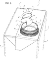
- Number 1 indicates as a whole a package for a pourable product, in particular a pourable food product, even more particular a liquid food product, comprising:
- main body 2 may be obtained from a packaging material, in particular a composite packaging material, having a multilayer structure (not shown and known as such).
- main body 2 may be obtained from a respective blank.
- the packaging material may be provided in the form of a web.
- main body 2 may be obtained by forming a tube from the packaging material, longitudinally sealing the tube, filling the tube with the pourable product and by transversally sealing and cutting the tube.
- the packaging material may comprise at least one layer of fibrous material, such as e.g. a paper or cardboard, and at least two layers of heat-seal plastic material, e.g. polyethylene, interposing the layer of fibrous material in between one another.
- fibrous material such as e.g. a paper or cardboard
- heat-seal plastic material e.g. polyethylene
- the packaging material may also comprise a layer of gas- and light-barrier material, e.g. aluminum foil or ethylene vinyl alcohol (EVOH) film, in particular being arranged between one of the layers of the heat-seal plastic material and the layer of fibrous material.
- the packaging material may also comprise a further layer of heat-seal plastic material being interposed between the layer of gas- and light-barrier material and the layer of fibrous material.
- opening device 4 may be applied onto the packaging material and/or base package 2 prior, during and/or after the formation, filling and sealing of main body 2.
- opening device 4 may be applied onto the packaging material prior to arranging the packaging material within or during advancement of the packaging material through a packaging machine for forming, filling and sealing main bodies 2 from the packaging material.
- opening device 4 may be fused and/or welded and/or bond and/or molded onto main body 2 and/or the packaging material and around the designated pour outlet.
- main body 2 may extend along a longitudinal axis A, a first transversal axis B and a second transversal axis C.
- the extension of package 2 along longitudinal axis A may be larger than the extension of package 2 along first transversal axis B and second transversal axis C.
- main body 2 may be parallelepiped-shaped.
- main body 2 may have a tubular shape or any other shape.
- main body 2 may comprise a first wall portion 5, in particular being transversal, in particular perpendicular, to longitudinal axis A, and from which main body 2 extends along longitudinal axis A.
- first wall portion 5 may define a support surface of package 1, in particular main body 2, which is designed to be put in contact with a support, such as e.g. a shelf, in particular when, in use, being e.g. exposed within a sales point or when being stored.
- a support such as e.g. a shelf
- main body 2 may also comprise one or more lateral walls 6, in the specific case shown four, being (fixedly) connected to first wall portion 5 and extending, in particular substantially parallel to longitudinal axis A, from first wall portion 5.
- main body 2 may also comprise a second wall portion 7 opposite to first wall portion 5 and being (fixedly) connected to at least some of lateral walls 6.
- lateral walls 6 may be interposed between first wall portion 5 and second wall portion 7.
- second wall portion 7 may define a top wall portion.
- first wall portion 5 and second wall portion 7 may be parallel to one another.
- first wall portion 5 and second wall portion 7 may be inclined with respect to one another.
- second wall portion 7 may carry and/or comprise designated pour opening 3.
- package 1, in particular main body 2 may comprise an inner space 8 configured to contain and/or containing the pourable product.
- first wall portion 5, lateral walls 8 and second wall portion 7 delimit inner space 8.
- main body 2 may comprise a separation membrane (not shown and known as such) covering designated pour opening 3.
- the separation membrane may separate in the area of, in particular at, designated pour opening 3 inner space 8 from an outer environment.
- the separation membrane may comprise a gas- and light-barrier material, e.g. aluminum foil or ethylene vinyl alcohol (EVOH) film.
- the separation membrane may be fused together with a portion of opening device 4.
- opening device 4 comprises at least:
- (plastic) weakening line 12 is configured such that, in use, upon exertion of an opening force on covering membrane 11, covering membrane 11 (irreversibly) separates from base frame 10 along weakening line 12. In other words, upon exertion of the opening force weakening line 12 (irreversibly) ruptures so as to separate covering membrane 11 from base frame 10 along weakening line 12.
- covering membrane 11 is designed to cover and seal in cooperation with base frame 10 the designated pour opening.
- weakening line 12 comprises a first end 13 and a second end 14 distinct and separated from one another.
- weakening line 12 does not have an annular configuration and/or a closed-loop configuration.
- first end 13 and second end 14 are not in contact with one another.
- weakening line 12 may be arc-shaped.
- covering membrane 11 is further connected to base frame 10 along an (unrupturable) tethering portion 15 extending between first end 13 and second end 14.
- tethering portion 15 tethers covering membrane 11 to base frame 10 even after separation of covering membrane 11 from base frame 10 along weakening line 12. In this manner, one guarantees that covering membrane 11 remains connected to base frame 10 (and main body 2 and package 1 as a whole) avoiding the possibility of an incorrect disposal of covering membrane 11.
- tethering portion 15 is configured such that, in use, upon exertion of the opening force on covering membrane 11, covering membrane 11 remains attached to base frame 10 along tethering portion 15.
- unrupturable indicates that upon a normal use by a user tethering portion 15 does not rupture.
- the opening force suited to allow for the rupturing of weakening line 12 does not allow to rupture tethering portion 15.
- weakening line 12 together with tethering portion 15 may define an annular shape and while, in use, upon exertion of the opening force the weakening line 12 ruptures, tethering portion 15 remains intact.
- tethering portion 15 may be in contact with first end 13 and second end 14.
- the thickness of weakening line 12 may be smaller than the thickness of tethering portion 15.
- covering membrane 11 upon separation of covering membrane 11 from base frame 10 along weakening line 12, covering membrane 11 is angularly moveable around a hinge axis E defined by tethering portion 15.
- covering membrane 11 is angularly moveable from a closing position (see Figures 2 and 4 ) in which covering membrane 11 covers designated pour opening 3 to an opening position in which covering membrane 11 frees designated pour opening 3.
- covering membrane 11 is in the closing position, with covering membrane 11 being connected to base frame 10 along weakening line 12. Even more particular, covering membrane 11 is in the closing position, with weakening line 12 being intact.
- covering membrane 11 is angularly moveable between the opening position and a re-closing position, in which covering membrane 11 covers designated pour opening 3.
- covering membrane 11 may be configured such that prior to the first-time use (i.e. prior to the rupturing of weakening line 12) covering membrane 11 is positioned in the closing position and is designed to cover designated pouring outlet 3 and to also seal designated pouring outlet 3 in cooperation with base frame 10. Additionally, and with particular reference to Figure 5 , covering membrane 11 may be designed such that once covering membrane 11 is separated from base frame 10 along weakening line 12 (i.e. weakening line 12 is ruptured) covering membrane 11 may be in the re-closing position, in which covering membrane 11 covers designated pouring outlet 3, but does not seal designated pouring outlet 3 anymore.
- covering membrane 11 may be biased into the re-closing position, i.e. in the absence of the application of an external force on covering membrane 11, covering membrane 11 returns back to the re-closing position.
- opening device 4 may comprise a retaining element 16 (see further below for more details) configured to interact with covering membrane 11 so as to retain covering membrane 11 in the opening position, in particular so as to guarantee that covering membrane 11 does not disturb the outpouring of the pourable product from package 1, in particular main body 2.
- covering membrane 11 may comprise a first portion 17 and a second portion 18 being rupturably connected to one another along an auxiliary weakening line 19.
- auxiliary weakening line 19 may be configured such that, in use, upon exertion of the opening force, and in particular (substantially) simultaneously to the separation of covering membrane 11 from base frame 10, first portion 17 and second portion 18 separate from one another along auxiliary weakening line 19.
- auxiliary weakening line 19 may extend from second end 14.
- auxiliary weakening line 19 and second end 14 are (integrally) connected to one another.
- auxiliary weakening line 19 may extend from second end 14 towards, in particular to, a center 20 of covering membrane 11.
- auxiliary weakening line 19 may be transversal, in particular perpendicular, to weakening line 12.
- first portion 17 and second portion 18 may be configured to interact with retaining element 16 for retaining covering membrane 11 in the opening position.
- first portion 17 and second portion 18 may be configured to hook up with retaining element 16 for retaining covering membrane 11 in the opening position.
- first portion 17 and second portion 18 may be arrangeable such to interpose and/or clamp at least a portion of retaining element 16 between one another for retaining covering membrane 11 in the opening position.
- covering membrane 11 is (substantially) flush with main body 2, in particular second wall portion 7, in particular when being in the closed position.
- covering membrane 11 may be fused with the separation membrane.
- separation membrane may be considered to be part of covering membrane 11.
- opening device 4 may further comprise an opening element 25 connected to covering membrane 11 and configured to allow for the exertion of the opening force on covering membrane 11.
- opening element 25 may be configured to be operated by a consumer so as to exert the opening force.
- opening element 25 may comprise a pull leg 26, in particular a single pull leg 26, connected to covering membrane 11, in particular to a peripheral portion of covering membrane 11. Additionally, opening element 25 may comprise a gripping element 27, for example a ring, connected to pull leg 26 and being designed to be gripped by the consumer.
- pull leg 26 may be arranged at a peripheral portion of covering membrane 11 being opposed to a portion of covering membrane 11 being integrally connected to tethering portion 15.
- pull leg 26 may transversally, in particular (substantially) perpendicularly, extend from covering membrane 11.
- opening element 25, in particular pull leg 26, may be connected to covering membrane 11 at a connecting point, in particular a single connecting point.
- pull leg 26 may be arranged adjacent to second end 14 and auxiliary weakening line 19.
- opening device 4 may further comprise a collar 28 extending from base frame 10 and having an outlet 29, in particular being aligned, even more particular being coaxial, with respect to designated pouring outlet 3.
- collar 28 being designed to allow for a controlled outpouring of the pourable product from package 1, in particular main body 2.
- collar 28 may define retaining element 16. In this manner, one avoids providing opening device 4 with further components.
- first portion 17 and second portion 18 may be arranged and/or arrangeable so as to contact collar 28 from opposite sides thereof for retaining covering membrane 11 in the opening position.
- base frame 10 covering membrane 11, weakening line 12, tethering portion 15, and in particular collar 28, may be obtained, in particular by molding, as a single piece.
- base frame 10 covering membrane 11, weakening line 12, tethering portion 15, and in particular collar 28, may be molded onto main body 2 and/or onto the packaging material from which main body 2 is formed.
- opening device 4 may also comprise a lid 30 coupled and/or couplable to collar 28 and configured to selectively close and open outlet 29.
- lid 30 is of the screw-lid type.
- lid 30 could be of any other type.
- opening device 4 may also comprise a coupling ring 31 coupled to and arranged around collar 28.
- lid 30 may be tethered to coupling ring 31.
- lid 30 may be at least arrangeable in a closed position, in which lid 30 covers outlet 29, and an open position, in which lid 30 is removed from outlet 29.
- a consumer needs to exert the opening force, in particular by relying on opening element 25, on covering membrane 11 so as to separate covering membrane 11 from base frame 10 along weakening line 12. Moreover, the exertion of the opening force also leads to the separation of first portion 17 and second portion 18 along auxiliary weakening line 19.
- lid 30 prior to being able to manipulate covering membrane 11 the user needs to arrange lid 30 in the open position.
- covering membrane 11 may be retained by retaining element 16, in particular collar 28, in the opening position.
- the consumer can arrange covering membrane 11 in the re-closing position, and in particular also arrange lid 30 in the closed position.
- opening device 4 and/or of package 1 according to the present invention will be clear from the foregoing description.
- first portion 17 and second portion 18, which may be arranged and/or arrangeable so as to contact retaining element 16, in particular collar 28, from opposite sides thereof for maintaining covering membrane 11 in the opening position.
Landscapes
- Engineering & Computer Science (AREA)
- Mechanical Engineering (AREA)
- Packages (AREA)
- Closures For Containers (AREA)
Applications Claiming Priority (1)
| Application Number | Priority Date | Filing Date | Title |
|---|---|---|---|
| EP21169406 | 2021-04-20 |
Publications (3)
| Publication Number | Publication Date |
|---|---|
| EP4079652A1 true EP4079652A1 (fr) | 2022-10-26 |
| EP4079652C0 EP4079652C0 (fr) | 2023-11-15 |
| EP4079652B1 EP4079652B1 (fr) | 2023-11-15 |
Family
ID=75625350
Family Applications (1)
| Application Number | Title | Priority Date | Filing Date |
|---|---|---|---|
| EP22167960.8A Active EP4079652B1 (fr) | 2021-04-20 | 2022-04-12 | Dispositif d'ouverture pour un emballage et emballage pourvu d'un dispositif d'ouverture |
Country Status (3)
| Country | Link |
|---|---|
| EP (1) | EP4079652B1 (fr) |
| ES (1) | ES2972489T3 (fr) |
| WO (1) | WO2022223374A1 (fr) |
Citations (3)
| Publication number | Priority date | Publication date | Assignee | Title |
|---|---|---|---|---|
| JPH0789535A (ja) * | 1993-06-30 | 1995-04-04 | Dainippon Printing Co Ltd | ブリック型紙容器 |
| WO1996014249A2 (fr) * | 1994-11-07 | 1996-05-17 | Capitol Spouts, Inc. | Recipient a bec verseur perfectionne pouvant se refermer, et procede associe |
| EP3715271A1 (fr) * | 2019-03-26 | 2020-09-30 | Tetra Laval Holdings & Finance S.A. | Dispositif d'ouverture pour un emballage contenant un produit versable |
-
2022
- 2022-04-12 WO PCT/EP2022/059782 patent/WO2022223374A1/fr active Application Filing
- 2022-04-12 EP EP22167960.8A patent/EP4079652B1/fr active Active
- 2022-04-12 ES ES22167960T patent/ES2972489T3/es active Active
Patent Citations (3)
| Publication number | Priority date | Publication date | Assignee | Title |
|---|---|---|---|---|
| JPH0789535A (ja) * | 1993-06-30 | 1995-04-04 | Dainippon Printing Co Ltd | ブリック型紙容器 |
| WO1996014249A2 (fr) * | 1994-11-07 | 1996-05-17 | Capitol Spouts, Inc. | Recipient a bec verseur perfectionne pouvant se refermer, et procede associe |
| EP3715271A1 (fr) * | 2019-03-26 | 2020-09-30 | Tetra Laval Holdings & Finance S.A. | Dispositif d'ouverture pour un emballage contenant un produit versable |
Also Published As
| Publication number | Publication date |
|---|---|
| WO2022223374A1 (fr) | 2022-10-27 |
| EP4079652C0 (fr) | 2023-11-15 |
| ES2972489T3 (es) | 2024-06-13 |
| EP4079652B1 (fr) | 2023-11-15 |
Similar Documents
| Publication | Publication Date | Title |
|---|---|---|
| EP3892562A1 (fr) | Ensemble couvercle pour un emballage, groupe couvercle-bec verseur pour un emballage et emballage comportant un groupe couvercle-bec verseur | |
| US20230137895A1 (en) | Spout for a package, lid-spout assembly for a package and package having a spout | |
| EP3892560A1 (fr) | Ensemble couvercle-bec verseur pour un emballage et emballage doté d'un ensemble couvercle-bec verseur | |
| EP3892559B1 (fr) | Ensemble couvercle-bec verseur pour un emballage et emballage doté d'un tel ensemble | |
| EP3892561B1 (fr) | Ensemble couvercle pour un bec verseur d'un emballage, groupe couvercle-bec verseur pour un emballage et emballage comportant un ensemble couvercle | |
| EP3892564A1 (fr) | Bec verseur pour un emballage, ensemble couvercle-bec verseur pour un emballage et emballage doté d'un bec verseur | |
| EP4159633A1 (fr) | Dispositif d'ouverture pour un emballage, moule pour mouler un dispositif d'ouverture pour un emballage et emballage doté d'un dispositif d'ouverture | |
| EP4079652B1 (fr) | Dispositif d'ouverture pour un emballage et emballage pourvu d'un dispositif d'ouverture | |
| EP4234424B1 (fr) | Bec pour un récipient et ensemble emballage-bec | |
| EP4159631B1 (fr) | Dispositif d'ouverture pour un emballage, moule pour mouler un dispositif d'ouverture pour un emballage et emballage doté d'un dispositif d'ouverture | |
| EP4159634B1 (fr) | Dispositif d'ouverture pour un emballage, moule pour mouler un dispositif d'ouverture pour un emballage et emballage doté d'un dispositif d'ouverture | |
| EP4177181A1 (fr) | Dispositif d'ouverture pour un emballage et emballage doté d'un dispositif d'ouverture | |
| EP4001150A1 (fr) | Ensemble couvercle-bec verseur pour un emballage et emballage doté d'un ensemble couvercle-bec verseur | |
| EP4001149A1 (fr) | Dispositif d'ouverture pour un emballage et emballage pourvu d'un dispositif d'ouverture | |
| US20230182972A1 (en) | Lid-spout assembly for a package and package having a lid-spout assembly |
Legal Events
| Date | Code | Title | Description |
|---|---|---|---|
| PUAI | Public reference made under article 153(3) epc to a published international application that has entered the european phase |
Free format text: ORIGINAL CODE: 0009012 |
|
| STAA | Information on the status of an ep patent application or granted ep patent |
Free format text: STATUS: THE APPLICATION HAS BEEN PUBLISHED |
|
| AK | Designated contracting states |
Kind code of ref document: A1 Designated state(s): AL AT BE BG CH CY CZ DE DK EE ES FI FR GB GR HR HU IE IS IT LI LT LU LV MC MK MT NL NO PL PT RO RS SE SI SK SM TR |
|
| STAA | Information on the status of an ep patent application or granted ep patent |
Free format text: STATUS: REQUEST FOR EXAMINATION WAS MADE |
|
| 17P | Request for examination filed |
Effective date: 20230426 |
|
| RBV | Designated contracting states (corrected) |
Designated state(s): AL AT BE BG CH CY CZ DE DK EE ES FI FR GB GR HR HU IE IS IT LI LT LU LV MC MK MT NL NO PL PT RO RS SE SI SK SM TR |
|
| GRAP | Despatch of communication of intention to grant a patent |
Free format text: ORIGINAL CODE: EPIDOSNIGR1 |
|
| STAA | Information on the status of an ep patent application or granted ep patent |
Free format text: STATUS: GRANT OF PATENT IS INTENDED |
|
| RIC1 | Information provided on ipc code assigned before grant |
Ipc: B65D 55/16 20060101ALI20230615BHEP Ipc: B65D 5/74 20060101AFI20230615BHEP |
|
| INTG | Intention to grant announced |
Effective date: 20230703 |
|
| GRAS | Grant fee paid |
Free format text: ORIGINAL CODE: EPIDOSNIGR3 |
|
| GRAA | (expected) grant |
Free format text: ORIGINAL CODE: 0009210 |
|
| STAA | Information on the status of an ep patent application or granted ep patent |
Free format text: STATUS: THE PATENT HAS BEEN GRANTED |
|
| AK | Designated contracting states |
Kind code of ref document: B1 Designated state(s): AL AT BE BG CH CY CZ DE DK EE ES FI FR GB GR HR HU IE IS IT LI LT LU LV MC MK MT NL NO PL PT RO RS SE SI SK SM TR |
|
| REG | Reference to a national code |
Ref country code: CH Ref legal event code: EP Ref country code: GB Ref legal event code: FG4D |
|
| REG | Reference to a national code |
Ref country code: DE Ref legal event code: R096 Ref document number: 602022000982 Country of ref document: DE |
|
| REG | Reference to a national code |
Ref country code: IE Ref legal event code: FG4D |
|
| U01 | Request for unitary effect filed |
Effective date: 20231130 |
|
| U07 | Unitary effect registered |
Designated state(s): AT BE BG DE DK EE FI FR IT LT LU LV MT NL PT SE SI Effective date: 20231206 |
|
| PG25 | Lapsed in a contracting state [announced via postgrant information from national office to epo] |
Ref country code: GR Free format text: LAPSE BECAUSE OF FAILURE TO SUBMIT A TRANSLATION OF THE DESCRIPTION OR TO PAY THE FEE WITHIN THE PRESCRIBED TIME-LIMIT Effective date: 20240216 |
|
| PG25 | Lapsed in a contracting state [announced via postgrant information from national office to epo] |
Ref country code: IS Free format text: LAPSE BECAUSE OF FAILURE TO SUBMIT A TRANSLATION OF THE DESCRIPTION OR TO PAY THE FEE WITHIN THE PRESCRIBED TIME-LIMIT Effective date: 20240315 |
|
| PG25 | Lapsed in a contracting state [announced via postgrant information from national office to epo] |
Ref country code: IS Free format text: LAPSE BECAUSE OF FAILURE TO SUBMIT A TRANSLATION OF THE DESCRIPTION OR TO PAY THE FEE WITHIN THE PRESCRIBED TIME-LIMIT Effective date: 20240315 Ref country code: GR Free format text: LAPSE BECAUSE OF FAILURE TO SUBMIT A TRANSLATION OF THE DESCRIPTION OR TO PAY THE FEE WITHIN THE PRESCRIBED TIME-LIMIT Effective date: 20240216 |
|
| PG25 | Lapsed in a contracting state [announced via postgrant information from national office to epo] |
Ref country code: RS Free format text: LAPSE BECAUSE OF FAILURE TO SUBMIT A TRANSLATION OF THE DESCRIPTION OR TO PAY THE FEE WITHIN THE PRESCRIBED TIME-LIMIT Effective date: 20231115 Ref country code: PL Free format text: LAPSE BECAUSE OF FAILURE TO SUBMIT A TRANSLATION OF THE DESCRIPTION OR TO PAY THE FEE WITHIN THE PRESCRIBED TIME-LIMIT Effective date: 20231115 Ref country code: NO Free format text: LAPSE BECAUSE OF FAILURE TO SUBMIT A TRANSLATION OF THE DESCRIPTION OR TO PAY THE FEE WITHIN THE PRESCRIBED TIME-LIMIT Effective date: 20240215 Ref country code: HR Free format text: LAPSE BECAUSE OF FAILURE TO SUBMIT A TRANSLATION OF THE DESCRIPTION OR TO PAY THE FEE WITHIN THE PRESCRIBED TIME-LIMIT Effective date: 20231115 |
|
| U20 | Renewal fee paid [unitary effect] |
Year of fee payment: 3 Effective date: 20240429 |
|
| REG | Reference to a national code |
Ref country code: ES Ref legal event code: FG2A Ref document number: 2972489 Country of ref document: ES Kind code of ref document: T3 Effective date: 20240613 |
|
| PGFP | Annual fee paid to national office [announced via postgrant information from national office to epo] |
Ref country code: ES Payment date: 20240516 Year of fee payment: 3 |
|
| PG25 | Lapsed in a contracting state [announced via postgrant information from national office to epo] |
Ref country code: CZ Free format text: LAPSE BECAUSE OF FAILURE TO SUBMIT A TRANSLATION OF THE DESCRIPTION OR TO PAY THE FEE WITHIN THE PRESCRIBED TIME-LIMIT Effective date: 20231115 |
|
| PG25 | Lapsed in a contracting state [announced via postgrant information from national office to epo] |
Ref country code: SK Free format text: LAPSE BECAUSE OF FAILURE TO SUBMIT A TRANSLATION OF THE DESCRIPTION OR TO PAY THE FEE WITHIN THE PRESCRIBED TIME-LIMIT Effective date: 20231115 |
|
| PG25 | Lapsed in a contracting state [announced via postgrant information from national office to epo] |
Ref country code: SM Free format text: LAPSE BECAUSE OF FAILURE TO SUBMIT A TRANSLATION OF THE DESCRIPTION OR TO PAY THE FEE WITHIN THE PRESCRIBED TIME-LIMIT Effective date: 20231115 Ref country code: SK Free format text: LAPSE BECAUSE OF FAILURE TO SUBMIT A TRANSLATION OF THE DESCRIPTION OR TO PAY THE FEE WITHIN THE PRESCRIBED TIME-LIMIT Effective date: 20231115 Ref country code: RO Free format text: LAPSE BECAUSE OF FAILURE TO SUBMIT A TRANSLATION OF THE DESCRIPTION OR TO PAY THE FEE WITHIN THE PRESCRIBED TIME-LIMIT Effective date: 20231115 Ref country code: CZ Free format text: LAPSE BECAUSE OF FAILURE TO SUBMIT A TRANSLATION OF THE DESCRIPTION OR TO PAY THE FEE WITHIN THE PRESCRIBED TIME-LIMIT Effective date: 20231115 |
|
| REG | Reference to a national code |
Ref country code: DE Ref legal event code: R097 Ref document number: 602022000982 Country of ref document: DE |
|
| PLBE | No opposition filed within time limit |
Free format text: ORIGINAL CODE: 0009261 |
|
| STAA | Information on the status of an ep patent application or granted ep patent |
Free format text: STATUS: NO OPPOSITION FILED WITHIN TIME LIMIT |