EP4079568A1 - Power supply method of charger for electric vehicle - Google Patents
Power supply method of charger for electric vehicle Download PDFInfo
- Publication number
- EP4079568A1 EP4079568A1 EP20901724.3A EP20901724A EP4079568A1 EP 4079568 A1 EP4079568 A1 EP 4079568A1 EP 20901724 A EP20901724 A EP 20901724A EP 4079568 A1 EP4079568 A1 EP 4079568A1
- Authority
- EP
- European Patent Office
- Prior art keywords
- charger
- charging
- power
- chargers
- signal
- Prior art date
- Legal status (The legal status is an assumption and is not a legal conclusion. Google has not performed a legal analysis and makes no representation as to the accuracy of the status listed.)
- Granted
Links
Images





Classifications
-
- B—PERFORMING OPERATIONS; TRANSPORTING
- B60—VEHICLES IN GENERAL
- B60L—PROPULSION OF ELECTRICALLY-PROPELLED VEHICLES; SUPPLYING ELECTRIC POWER FOR AUXILIARY EQUIPMENT OF ELECTRICALLY-PROPELLED VEHICLES; ELECTRODYNAMIC BRAKE SYSTEMS FOR VEHICLES IN GENERAL; MAGNETIC SUSPENSION OR LEVITATION FOR VEHICLES; MONITORING OPERATING VARIABLES OF ELECTRICALLY-PROPELLED VEHICLES; ELECTRIC SAFETY DEVICES FOR ELECTRICALLY-PROPELLED VEHICLES
- B60L53/00—Methods of charging batteries, specially adapted for electric vehicles; Charging stations or on-board charging equipment therefor; Exchange of energy storage elements in electric vehicles
- B60L53/60—Monitoring or controlling charging stations
- B60L53/67—Controlling two or more charging stations
-
- B—PERFORMING OPERATIONS; TRANSPORTING
- B60—VEHICLES IN GENERAL
- B60L—PROPULSION OF ELECTRICALLY-PROPELLED VEHICLES; SUPPLYING ELECTRIC POWER FOR AUXILIARY EQUIPMENT OF ELECTRICALLY-PROPELLED VEHICLES; ELECTRODYNAMIC BRAKE SYSTEMS FOR VEHICLES IN GENERAL; MAGNETIC SUSPENSION OR LEVITATION FOR VEHICLES; MONITORING OPERATING VARIABLES OF ELECTRICALLY-PROPELLED VEHICLES; ELECTRIC SAFETY DEVICES FOR ELECTRICALLY-PROPELLED VEHICLES
- B60L53/00—Methods of charging batteries, specially adapted for electric vehicles; Charging stations or on-board charging equipment therefor; Exchange of energy storage elements in electric vehicles
- B60L53/60—Monitoring or controlling charging stations
-
- H—ELECTRICITY
- H02—GENERATION; CONVERSION OR DISTRIBUTION OF ELECTRIC POWER
- H02J—ELECTRIC POWER NETWORKS; CIRCUIT ARRANGEMENTS OR SYSTEMS FOR SUPPLYING OR DISTRIBUTING ELECTRIC POWER; SYSTEMS FOR STORING ELECTRIC ENERGY
- H02J3/00—Circuit arrangements for AC mains or AC distribution networks
- H02J3/12—Arrangements for adjusting voltage in AC networks by changing a characteristic of the network load
- H02J3/14—Arrangements for adjusting voltage in AC networks by changing a characteristic of the network load by switching loads on to, or off from, the networks, e.g. progressively balanced loading
-
- B—PERFORMING OPERATIONS; TRANSPORTING
- B60—VEHICLES IN GENERAL
- B60L—PROPULSION OF ELECTRICALLY-PROPELLED VEHICLES; SUPPLYING ELECTRIC POWER FOR AUXILIARY EQUIPMENT OF ELECTRICALLY-PROPELLED VEHICLES; ELECTRODYNAMIC BRAKE SYSTEMS FOR VEHICLES IN GENERAL; MAGNETIC SUSPENSION OR LEVITATION FOR VEHICLES; MONITORING OPERATING VARIABLES OF ELECTRICALLY-PROPELLED VEHICLES; ELECTRIC SAFETY DEVICES FOR ELECTRICALLY-PROPELLED VEHICLES
- B60L3/00—Electric devices on electrically-propelled vehicles for safety purposes; Monitoring operating variables, e.g. speed, deceleration or energy consumption
- B60L3/0023—Detecting, eliminating, remedying or compensating for drive train abnormalities, e.g. failures within the drive train
- B60L3/0046—Detecting, eliminating, remedying or compensating for drive train abnormalities, e.g. failures within the drive train relating to electric energy storage systems, e.g. batteries or capacitors
-
- B—PERFORMING OPERATIONS; TRANSPORTING
- B60—VEHICLES IN GENERAL
- B60L—PROPULSION OF ELECTRICALLY-PROPELLED VEHICLES; SUPPLYING ELECTRIC POWER FOR AUXILIARY EQUIPMENT OF ELECTRICALLY-PROPELLED VEHICLES; ELECTRODYNAMIC BRAKE SYSTEMS FOR VEHICLES IN GENERAL; MAGNETIC SUSPENSION OR LEVITATION FOR VEHICLES; MONITORING OPERATING VARIABLES OF ELECTRICALLY-PROPELLED VEHICLES; ELECTRIC SAFETY DEVICES FOR ELECTRICALLY-PROPELLED VEHICLES
- B60L53/00—Methods of charging batteries, specially adapted for electric vehicles; Charging stations or on-board charging equipment therefor; Exchange of energy storage elements in electric vehicles
- B60L53/10—Methods of charging batteries, specially adapted for electric vehicles; Charging stations or on-board charging equipment therefor; Exchange of energy storage elements in electric vehicles characterised by the energy transfer between the charging station and the vehicle
- B60L53/14—Conductive energy transfer
- B60L53/16—Connectors, e.g. plugs or sockets, specially adapted for charging electric vehicles
-
- B—PERFORMING OPERATIONS; TRANSPORTING
- B60—VEHICLES IN GENERAL
- B60L—PROPULSION OF ELECTRICALLY-PROPELLED VEHICLES; SUPPLYING ELECTRIC POWER FOR AUXILIARY EQUIPMENT OF ELECTRICALLY-PROPELLED VEHICLES; ELECTRODYNAMIC BRAKE SYSTEMS FOR VEHICLES IN GENERAL; MAGNETIC SUSPENSION OR LEVITATION FOR VEHICLES; MONITORING OPERATING VARIABLES OF ELECTRICALLY-PROPELLED VEHICLES; ELECTRIC SAFETY DEVICES FOR ELECTRICALLY-PROPELLED VEHICLES
- B60L53/00—Methods of charging batteries, specially adapted for electric vehicles; Charging stations or on-board charging equipment therefor; Exchange of energy storage elements in electric vehicles
- B60L53/30—Constructional details of charging stations
- B60L53/305—Communication interfaces
-
- B—PERFORMING OPERATIONS; TRANSPORTING
- B60—VEHICLES IN GENERAL
- B60L—PROPULSION OF ELECTRICALLY-PROPELLED VEHICLES; SUPPLYING ELECTRIC POWER FOR AUXILIARY EQUIPMENT OF ELECTRICALLY-PROPELLED VEHICLES; ELECTRODYNAMIC BRAKE SYSTEMS FOR VEHICLES IN GENERAL; MAGNETIC SUSPENSION OR LEVITATION FOR VEHICLES; MONITORING OPERATING VARIABLES OF ELECTRICALLY-PROPELLED VEHICLES; ELECTRIC SAFETY DEVICES FOR ELECTRICALLY-PROPELLED VEHICLES
- B60L53/00—Methods of charging batteries, specially adapted for electric vehicles; Charging stations or on-board charging equipment therefor; Exchange of energy storage elements in electric vehicles
- B60L53/30—Constructional details of charging stations
- B60L53/31—Charging columns specially adapted for electric vehicles
-
- B—PERFORMING OPERATIONS; TRANSPORTING
- B60—VEHICLES IN GENERAL
- B60L—PROPULSION OF ELECTRICALLY-PROPELLED VEHICLES; SUPPLYING ELECTRIC POWER FOR AUXILIARY EQUIPMENT OF ELECTRICALLY-PROPELLED VEHICLES; ELECTRODYNAMIC BRAKE SYSTEMS FOR VEHICLES IN GENERAL; MAGNETIC SUSPENSION OR LEVITATION FOR VEHICLES; MONITORING OPERATING VARIABLES OF ELECTRICALLY-PROPELLED VEHICLES; ELECTRIC SAFETY DEVICES FOR ELECTRICALLY-PROPELLED VEHICLES
- B60L53/00—Methods of charging batteries, specially adapted for electric vehicles; Charging stations or on-board charging equipment therefor; Exchange of energy storage elements in electric vehicles
- B60L53/60—Monitoring or controlling charging stations
- B60L53/62—Monitoring or controlling charging stations in response to charging parameters, e.g. current, voltage or electrical charge
-
- B—PERFORMING OPERATIONS; TRANSPORTING
- B60—VEHICLES IN GENERAL
- B60L—PROPULSION OF ELECTRICALLY-PROPELLED VEHICLES; SUPPLYING ELECTRIC POWER FOR AUXILIARY EQUIPMENT OF ELECTRICALLY-PROPELLED VEHICLES; ELECTRODYNAMIC BRAKE SYSTEMS FOR VEHICLES IN GENERAL; MAGNETIC SUSPENSION OR LEVITATION FOR VEHICLES; MONITORING OPERATING VARIABLES OF ELECTRICALLY-PROPELLED VEHICLES; ELECTRIC SAFETY DEVICES FOR ELECTRICALLY-PROPELLED VEHICLES
- B60L53/00—Methods of charging batteries, specially adapted for electric vehicles; Charging stations or on-board charging equipment therefor; Exchange of energy storage elements in electric vehicles
- B60L53/60—Monitoring or controlling charging stations
- B60L53/63—Monitoring or controlling charging stations in response to network capacity
-
- B—PERFORMING OPERATIONS; TRANSPORTING
- B60—VEHICLES IN GENERAL
- B60L—PROPULSION OF ELECTRICALLY-PROPELLED VEHICLES; SUPPLYING ELECTRIC POWER FOR AUXILIARY EQUIPMENT OF ELECTRICALLY-PROPELLED VEHICLES; ELECTRODYNAMIC BRAKE SYSTEMS FOR VEHICLES IN GENERAL; MAGNETIC SUSPENSION OR LEVITATION FOR VEHICLES; MONITORING OPERATING VARIABLES OF ELECTRICALLY-PROPELLED VEHICLES; ELECTRIC SAFETY DEVICES FOR ELECTRICALLY-PROPELLED VEHICLES
- B60L53/00—Methods of charging batteries, specially adapted for electric vehicles; Charging stations or on-board charging equipment therefor; Exchange of energy storage elements in electric vehicles
- B60L53/60—Monitoring or controlling charging stations
- B60L53/66—Data transfer between charging stations and vehicles
- B60L53/665—Methods related to measuring, billing or payment
-
- B—PERFORMING OPERATIONS; TRANSPORTING
- B60—VEHICLES IN GENERAL
- B60L—PROPULSION OF ELECTRICALLY-PROPELLED VEHICLES; SUPPLYING ELECTRIC POWER FOR AUXILIARY EQUIPMENT OF ELECTRICALLY-PROPELLED VEHICLES; ELECTRODYNAMIC BRAKE SYSTEMS FOR VEHICLES IN GENERAL; MAGNETIC SUSPENSION OR LEVITATION FOR VEHICLES; MONITORING OPERATING VARIABLES OF ELECTRICALLY-PROPELLED VEHICLES; ELECTRIC SAFETY DEVICES FOR ELECTRICALLY-PROPELLED VEHICLES
- B60L58/00—Methods or circuit arrangements for monitoring or controlling batteries or fuel cells, specially adapted for electric vehicles
- B60L58/10—Methods or circuit arrangements for monitoring or controlling batteries or fuel cells, specially adapted for electric vehicles for monitoring or controlling batteries
- B60L58/12—Methods or circuit arrangements for monitoring or controlling batteries or fuel cells, specially adapted for electric vehicles for monitoring or controlling batteries responding to state of charge [SoC]
-
- G—PHYSICS
- G05—CONTROLLING; REGULATING
- G05B—CONTROL OR REGULATING SYSTEMS IN GENERAL; FUNCTIONAL ELEMENTS OF SUCH SYSTEMS; MONITORING OR TESTING ARRANGEMENTS FOR SUCH SYSTEMS OR ELEMENTS
- G05B15/00—Systems controlled by a computer
- G05B15/02—Systems controlled by a computer electric
-
- H—ELECTRICITY
- H02—GENERATION; CONVERSION OR DISTRIBUTION OF ELECTRIC POWER
- H02J—ELECTRIC POWER NETWORKS; CIRCUIT ARRANGEMENTS OR SYSTEMS FOR SUPPLYING OR DISTRIBUTING ELECTRIC POWER; SYSTEMS FOR STORING ELECTRIC ENERGY
- H02J7/00—Circuit arrangements for charging or discharging batteries or for supplying loads from batteries
- H02J7/50—Circuit arrangements for charging or discharging batteries or for supplying loads from batteries acting upon multiple batteries simultaneously or sequentially
-
- H—ELECTRICITY
- H02—GENERATION; CONVERSION OR DISTRIBUTION OF ELECTRIC POWER
- H02J—ELECTRIC POWER NETWORKS; CIRCUIT ARRANGEMENTS OR SYSTEMS FOR SUPPLYING OR DISTRIBUTING ELECTRIC POWER; SYSTEMS FOR STORING ELECTRIC ENERGY
- H02J7/00—Circuit arrangements for charging or discharging batteries or for supplying loads from batteries
- H02J7/90—Regulation of charging or discharging current or voltage
- H02J7/933—Regulation of charging or discharging current or voltage the cycle being controlled or terminated in response to electric parameters
-
- B—PERFORMING OPERATIONS; TRANSPORTING
- B60—VEHICLES IN GENERAL
- B60L—PROPULSION OF ELECTRICALLY-PROPELLED VEHICLES; SUPPLYING ELECTRIC POWER FOR AUXILIARY EQUIPMENT OF ELECTRICALLY-PROPELLED VEHICLES; ELECTRODYNAMIC BRAKE SYSTEMS FOR VEHICLES IN GENERAL; MAGNETIC SUSPENSION OR LEVITATION FOR VEHICLES; MONITORING OPERATING VARIABLES OF ELECTRICALLY-PROPELLED VEHICLES; ELECTRIC SAFETY DEVICES FOR ELECTRICALLY-PROPELLED VEHICLES
- B60L2260/00—Operating Modes
- B60L2260/40—Control modes
-
- B—PERFORMING OPERATIONS; TRANSPORTING
- B60—VEHICLES IN GENERAL
- B60Y—INDEXING SCHEME RELATING TO ASPECTS CROSS-CUTTING VEHICLE TECHNOLOGY
- B60Y2200/00—Type of vehicle
- B60Y2200/90—Vehicles comprising electric prime movers
- B60Y2200/91—Electric vehicles
-
- H—ELECTRICITY
- H02—GENERATION; CONVERSION OR DISTRIBUTION OF ELECTRIC POWER
- H02J—ELECTRIC POWER NETWORKS; CIRCUIT ARRANGEMENTS OR SYSTEMS FOR SUPPLYING OR DISTRIBUTING ELECTRIC POWER; SYSTEMS FOR STORING ELECTRIC ENERGY
- H02J2105/00—Networks for supplying or distributing electric power characterised by their spatial reach or by the load
- H02J2105/30—Networks for supplying or distributing electric power characterised by their spatial reach or by the load the load networks being external to vehicles, i.e. exchanging power with vehicles
- H02J2105/33—Networks for supplying or distributing electric power characterised by their spatial reach or by the load the load networks being external to vehicles, i.e. exchanging power with vehicles exchanging power with road vehicles
- H02J2105/37—Networks for supplying or distributing electric power characterised by their spatial reach or by the load the load networks being external to vehicles, i.e. exchanging power with vehicles exchanging power with road vehicles exchanging power with electric vehicles [EV] or with hybrid electric vehicles [HEV]
-
- H—ELECTRICITY
- H02—GENERATION; CONVERSION OR DISTRIBUTION OF ELECTRIC POWER
- H02J—ELECTRIC POWER NETWORKS; CIRCUIT ARRANGEMENTS OR SYSTEMS FOR SUPPLYING OR DISTRIBUTING ELECTRIC POWER; SYSTEMS FOR STORING ELECTRIC ENERGY
- H02J2105/00—Networks for supplying or distributing electric power characterised by their spatial reach or by the load
- H02J2105/50—Networks for supplying or distributing electric power characterised by their spatial reach or by the load for selectively controlling the operation of the loads
- H02J2105/52—Networks for supplying or distributing electric power characterised by their spatial reach or by the load for selectively controlling the operation of the loads for limitation of the power consumption in the networks or in one section of the networks, e.g. load shedding or peak shaving
-
- Y—GENERAL TAGGING OF NEW TECHNOLOGICAL DEVELOPMENTS; GENERAL TAGGING OF CROSS-SECTIONAL TECHNOLOGIES SPANNING OVER SEVERAL SECTIONS OF THE IPC; TECHNICAL SUBJECTS COVERED BY FORMER USPC CROSS-REFERENCE ART COLLECTIONS [XRACs] AND DIGESTS
- Y02—TECHNOLOGIES OR APPLICATIONS FOR MITIGATION OR ADAPTATION AGAINST CLIMATE CHANGE
- Y02T—CLIMATE CHANGE MITIGATION TECHNOLOGIES RELATED TO TRANSPORTATION
- Y02T10/00—Road transport of goods or passengers
- Y02T10/60—Other road transportation technologies with climate change mitigation effect
- Y02T10/70—Energy storage systems for electromobility, e.g. batteries
-
- Y—GENERAL TAGGING OF NEW TECHNOLOGICAL DEVELOPMENTS; GENERAL TAGGING OF CROSS-SECTIONAL TECHNOLOGIES SPANNING OVER SEVERAL SECTIONS OF THE IPC; TECHNICAL SUBJECTS COVERED BY FORMER USPC CROSS-REFERENCE ART COLLECTIONS [XRACs] AND DIGESTS
- Y02—TECHNOLOGIES OR APPLICATIONS FOR MITIGATION OR ADAPTATION AGAINST CLIMATE CHANGE
- Y02T—CLIMATE CHANGE MITIGATION TECHNOLOGIES RELATED TO TRANSPORTATION
- Y02T10/00—Road transport of goods or passengers
- Y02T10/60—Other road transportation technologies with climate change mitigation effect
- Y02T10/7072—Electromobility specific charging systems or methods for batteries, ultracapacitors, supercapacitors or double-layer capacitors
-
- Y—GENERAL TAGGING OF NEW TECHNOLOGICAL DEVELOPMENTS; GENERAL TAGGING OF CROSS-SECTIONAL TECHNOLOGIES SPANNING OVER SEVERAL SECTIONS OF THE IPC; TECHNICAL SUBJECTS COVERED BY FORMER USPC CROSS-REFERENCE ART COLLECTIONS [XRACs] AND DIGESTS
- Y02—TECHNOLOGIES OR APPLICATIONS FOR MITIGATION OR ADAPTATION AGAINST CLIMATE CHANGE
- Y02T—CLIMATE CHANGE MITIGATION TECHNOLOGIES RELATED TO TRANSPORTATION
- Y02T90/00—Enabling technologies or technologies with a potential or indirect contribution to GHG emissions mitigation
- Y02T90/10—Technologies relating to charging of electric vehicles
- Y02T90/12—Electric charging stations
-
- Y—GENERAL TAGGING OF NEW TECHNOLOGICAL DEVELOPMENTS; GENERAL TAGGING OF CROSS-SECTIONAL TECHNOLOGIES SPANNING OVER SEVERAL SECTIONS OF THE IPC; TECHNICAL SUBJECTS COVERED BY FORMER USPC CROSS-REFERENCE ART COLLECTIONS [XRACs] AND DIGESTS
- Y02—TECHNOLOGIES OR APPLICATIONS FOR MITIGATION OR ADAPTATION AGAINST CLIMATE CHANGE
- Y02T—CLIMATE CHANGE MITIGATION TECHNOLOGIES RELATED TO TRANSPORTATION
- Y02T90/00—Enabling technologies or technologies with a potential or indirect contribution to GHG emissions mitigation
- Y02T90/10—Technologies relating to charging of electric vehicles
- Y02T90/16—Information or communication technologies improving the operation of electric vehicles
Definitions
- the present invention relates to a power supply method of an electric vehicle charger, and more particularly, to a power supply method of a charger for an electric vehicle that can efficiently control power distribution through communication between chargers connected to the same power supply source (power grid) without an external communication function.
- An electric vehicle (EV) is future convergence technology that is receiving attention and investment from governments and companies around the world along with the trend of a global green growth policy. Accordingly, the demand tendency of the automobile industry market is quickly changing from conventional oil-based vehicles to electric vehicles.
- a power supply source 10 includes a main charger 30 and multiple sub-chargers 40 directly controlled by the main charger 30.
- the main charger 30 directly controls the amount of power supplied to the sub-chargers 40 and is in charge of communication with an external server 20.
- the main charger 30 includes a measurement unit 31 for monitoring the amount of power used by the sub-chargers 40 and a unit charging amount, a power supply unit 32, a communication unit 33 for communicating with the server 20 and the sub-chargers 40, and a control unit 34 for controlling the number of sub-chargers to be operated or controlling a communication function
- the sub-charger 40 includes an outlet 41 built in the apparatus together with a fixed wiring and a connector 42 to be docked with an electric vehicle charging unit.
- the present invention has been created to solve the above problems and is directed to providing a power supply method of an electric vehicle charger that, by only using chargers that do not have a function of communicating with the outside, can efficiently distribute the amount of power to the chargers without a main charger.
- the present invention provides a power supply method of a charger for an electric vehicle capable of efficiently distributing the amount of electric power supplied by each charger to an electric vehicle within the maximum amount of electric power by enabling mutual communication between chargers connected to the same electric power supply source.
- a power supply method for a charger for an electric vehicle that can lower overall charger installation costs by not installing a separate main charger.
- a power supply method of an electric vehicle charger in which multiple chargers are connected to the same power supply source may include operations of: allowing an electric vehicle to be connected to a first charger, generating a charging start signal from the first charger, receiving, by one or more other chargers, the charging start signal, generating a charging state signal from the other chargers, receiving, by the first charger, the charging state signal; and determining the amount of supplied power of the first charger. Accordingly, by only using chargers that do not have a function of communicating with the outside, it is possible to efficiently distribute the amount of power to the chargers without a main charger.
- the operation of generating a charging state signal from the other chargers may include operations of determining whether an electric vehicle is connected to a second charger, generating a charging progress signal or a charging standby signal from the second charger, and transmitting the generated signal to the first charger, and the charging progress signal may be a signal generated when the electric vehicle is being charged, and the charging standby signal may be a signal generated when the second charger is on standby. Accordingly, it is possible for the chargers to share whether each charger is in use for charging with each other.
- the operation of generating a charging state signal may include operations of determining whether an electric vehicle is connected to a second charger and generating a charging progress signal from the second charger, the operation of receiving, by the first charger, the charging state signal may include an operation of checking whether the charging state signal is received within a set time, and when the charging state signal is not transmitted within the set time, the first charger determines that the second charger is on standby. Accordingly, it is possible for the chargers to share whether each charger is on standby with each other.
- the operation of determining the amount of supplied power of the first charger may include operations of storing the number of times the charging progress signal is received, computing the amount of power available for supply to the first charger, and supplying the power to the first charger, and the amount of power supplied to the first charger may reflect the number of times the charging progress signal is received. Accordingly, by only using chargers that do not have a function of communicating with the outside, it is possible to efficiently distribute the amount of power to the chargers without a main charger.
- the amount of power supplied to the first charger may be less than or equal to a value obtained by dividing the maximum amount of power by one greater than the number of times the charging progress signal is received. Accordingly, when two or more vehicles are charged through a charger in the same power supply source on the basis of the shared state of each charger, it is possible to properly distribute the amount of power.
- the operation of determining the amount of supplied power of the first charger may further include an operation of determining whether a fast charging mode is set, and when the fast charging mode is set, the first charger may receive more than a set amount of power from the power supply source. Accordingly, by allowing a user to set the fast charging mode according to his or her need, it is possible to increase charging efficiency and increase the profitability of charger providers.
- the operation of supplying the power to the first charger may include operations of generating a charging start time signal, generating a fast charging mode progress signal, and receiving, by the other chargers, the charging start time signal and the fast charging mode progress signal, and when the other chargers receive the fast charging mode progress signal, the maximum amount of power supplied from the power supply source is limited. Accordingly, it is possible to limit the number of chargers that can select the fast charging mode.
- the operation of supplying the power to the first charger may include operations of generating a charging start time signal and receiving, by the other chargers, the charging start time signal. Accordingly, by sharing a charging start time between chargers, it is possible to set a criterion that can be used for power distribution.
- the method may further include operations of terminating the charging of any one charger, generating a charging termination signal from the charger, receiving, by the other chargers, the charging termination signal; and determining the amount of supplied power of the other chargers. Accordingly, it is possible to share whether the charging of each charger is terminated.
- the operation of determining the amount of supplied power of the other chargers may include operations of checking a charging start time signal received by a third charger and determining the amount of power distributed to the third charger. Accordingly, based on the shared state of each charger, it is possible to supply more idle power to chargers that are in use for charging.
- the operation of determining the amount of power distributed to the third charger may include operations of comparing a charging start time of the third charger to the received charging start time signal and calculating priority, and the amount of distributed power may be determined according to the calculated priority.
- a power supply system of an electric vehicle charger includes multiple chargers connected to the same power supply source and configured to communicate with each other, and when an electric vehicle is connected to one charger, a charging start signal is transmitted from the charger to which the electric vehicle is connected to one or more other chargers, a charging state signal is transmitted from the other chargers to the charger to which the electric vehicle is connected, and the amount of power supplied to the charger to which the electric vehicle is connected is determined according to the charging state signal. Accordingly, by only using chargers that do not have a function of communicating with the outside, it is possible to efficiently distribute the amount of power to the chargers.
- each of the chargers may include a connector connected to an electric vehicle and configured to supply power, a control unit configured to control the amount of power supplied to the connector, the control unit including a communication unit in charge of communication with other chargers, and a connection unit connected to a power supply source and configured to perform a fast charging mode or a slow charging mode according to a signal of the control unit.
- At least one of the multiple chargers may be capable of communicating with an external server. Accordingly, by setting one charger capable of communicating with an external server for payment, it is possible to help smooth payment of the other chargers.
- At least one of the multiple chargers may be a movable charger including a movable means for moving to a location where an electric vehicle is parked.
- unit refers to a software element or a hardware element such as a field-programmable gate array (FPGA) or an application-specific integrated circuit (ASIC), and a “unit” or “module” performs any role.
- FPGA field-programmable gate array
- ASIC application-specific integrated circuit
- a “unit” or “module” is not limited to software or hardware.
- a “unit” or “module” may be configured to reside in an addressable storage medium or to execute one or more processors.
- a "unit” or “module” includes elements, such as software elements, object-oriented software elements, class elements, and task elements, processes, functions, attributes, procedures, subroutines, segments of program code, drivers, firmware, microcode, circuits, data, database, data structures, tables, arrays, and variables.
- functions provided in elements and "units” or “modules” may be combined into as a smaller number of elements and “units” or further divided into additional elements and "units.”
- a computer refers to any kind of hardware device including at least one processor and may be understood as encompassing software configurations operating in corresponding hardware devices depending on the embodiment.
- a computer may be understood as including smartphones, tablet PCs, desktops, notebooks, and user clients and applications running in such devices.
- the present invention is not limited thereto.
- each operation will be described as being performed by a computer, but the subject of each operation is not limited thereto, and at least some of the operations may be performed in different devices depending on the embodiment.
- an electric vehicle charging system may be defined as a system that basically charges a battery mounted in an electric vehicle by using electric power of an energy storage device or a commercial power supply source.
- Such an electric vehicle charging system may have various forms depending on the type of electric vehicle.
- the electric vehicle charging system may include a cable-based conductive charging system or a non-contact wireless power transmission system.
- an electric vehicle may be referred to as an electric car, an electric automobile, an electric road vehicle (ERV), a plugin vehicle (PV or xEV), and the like
- a power supply source may include residential or public electric service or a generator that uses vehicle-mounted fuel.
- connection between an electric vehicle and a charger may refer to a procedure in which a connector (or wireless charging device) disposed to transmit power is associated with the electric vehicle.
- the procedure includes a process of exchanging information necessary for command and control communication, control, and termination between the electric vehicle and the charger.
- the charger includes not only wired charging but also wireless charging.
- a wireless power charging system may refer to a system for control between a GA and a VA including wireless power transmission and alignment and communication.
- Wireless power transfer may refer to transferring electrical power from an alternating current (AC) power supply network to an electric vehicle through contactless means.
- AC alternating current
- chargers can communicate with each other.
- Various methods may be applied for communication between chargers. For example, Bluetooth that communicates within a short distance of less than 10 m, a beacon that communicates within a short distance of less than 70 m, Addictive Links Online Hawaii Area (ALOHA) corresponding to a contention-type multiple access protocol that randomly accesses a common transmission channel without central control, Wi-Fi, PLC communication, and P2P communication may be applied.
- ALOHA Addictive Links Online Hawaii Area
- the charger according to an embodiment of the present invention may be a charger that corresponds to one of a fast charger or a slow charger or a charger to which the two modes are applied.
- FIG. 2 is a conceptual diagram illustrating a power distribution method of an electric vehicle charger according to an embodiment of the present invention.
- the power supply source 200 has a limit to the power available for supply, and this limit of power may be defined as the maximum amount of power. In the case of a building, the maximum power available for supply to one building may be defined as the maximum amount of power.
- Electricity from the power supply source 200 is supplied to the charger 100 through a distribution box 210, a meter 220, and a power supply unit 230.
- the distribution box 210 is an element that has a function of receiving electricity from the outside, supplying electricity to the power supply unit 230, and shutting off electricity in case of failure.
- the meter 220 is a meter that measures and records the total amount of power used for a certain period of time.
- the power supply unit 230 has the same configuration as an outlet and is an element to which the charger 100 is directly connected to receive power. Meanwhile, the electricity of the power supply source 200 may be directly connected to chargers through wires without the power supply unit 230. Depending on the installation environment or the nature of the charger, the power supply unit 230 may be selectively applied.
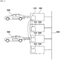
- Multiple chargers 100 may be installed at one power supply source 200, and the number of installed chargers may be limited by the maximum amount of power that can be supplied by the power supply source 200.
- the multiple chargers 100 connected to one power supply source 200 may be installed in a mixture of various types.
- some of the multiple chargers may be stationary chargers 100, and the others may be movable chargers 100'.
- the stationary charger 100 is directly connected to the power supply unit 230, and for charging, an electric vehicle 300 should be driven in front of the charger 100.
- the movable charger 100' includes a power connection unit 101' coupled to the power supply unit 230 and a moving means that can move to where the electric vehicle 300 is parked. In the charging standby state, the movable charger 100' is connected to the power connection unit 101' to receive electricity from the power supply source 200. When a charging request is received through an application or various communication means, the movable charger 100' moves to where the electric vehicle 300 is located according to the charging request signal and performs the charging of the electric vehicle 300.
- At least one of a wired charging method and a wireless charging method may be applied to the multiple chargers 100, and the wired and/or wireless charging methods may be applied to both the stationary charger 100 and the movable charger 100'.
- Each charger 100 includes a connector 110 directly connected to the electric vehicle 300 to supply power, a control unit 120 for controlling the amount of power supplied to the connector 110, and a connection unit 130 connected to the power supply unit 230.
- the charger 100 may include a wireless charging panel.
- the connection unit 130 is not provided together with the power supply unit 230. According to the installation environment of the charger and the specifications of the charger, the connection unit 130 may be selectively applied.
- the electric vehicle 300 may include a communication controller 310 for communicating with other external devices, and the communication controller 310 is an element that can communicate with the connector 110 and a user terminal.
- the communication between the electric vehicle 300 and the charger may be made only when the charger is a DC fast charger. On the other hand, in the case of a slow charger, it is common that the communication between the charger and the electric vehicle 300 is not made.
- a main charger or a central control unit for collectively controlling the multiple chargers 100 is not provided. It is possible to control the amount of power supplied to each charger only with general chargers without a separate central control unit or main charger. Specifically, the multiple chargers 100 are provided to communicate with each other, and the detailed configuration of the charger 100 will be described with reference to FIG. 3 .
- FIG. 3 is a schematic diagram of detailed elements constituting each charger 100.
- the connector 110 includes a first connector 111 and a second connector 112 which are directly connected to the electric vehicle 300 to supply power.
- the first connector 111 is a charging terminal for supporting charging in a combo 1 method and is formed of a combination of a single-phase AC slow charging socket and a DC fast charging socket. This is mainly used in the United States.
- the second connector 112 is a charging terminal for supporting charging in a combo 2 method and is formed of a combination of a three-phase AC slow charging socket and a DC fast charging socket. This is mainly used in Europe.
- the second connector 112 can be applied to more various situations and vehicles than the first connector 111 because there are various charging methods for supporting the second connector 112, such as DC single charging, DC and three-phase AC power, DC and single-phase AC power, and three-phase AC single charging.
- the scope of the present invention for the connector 110 is not limited thereto.
- At least one of the first connector 111 and the second connector 112 may be applied as the connector 110, and another type of connector, for example, a J1772 slow connector, may be applied.
- the charger may not be provided with a connector and a cable.
- the socket is installed in the charger, and the connector or cable may be separately purchased and used by a user who wants to use the charger.
- the control unit 120 may be composed of one or more processors and memories or may be composed of a computer.
- the control unit 120 is in charge of communication with the charger 100 connected to the same power supply source 200 and the control of the amount of power supplied to the connected electric vehicle 300.
- control unit 120 may include an input unit 121, a display unit 122, a relay unit 123, a payment unit 124, and a communication unit 125.
- input unit 121 a display unit 122
- relay unit 123 a relay unit 123
- payment unit 124 a payment unit 124
- communication unit 125 a communication unit 125
- some of the above elements may be omitted, and a separate element may be further added if necessary.
- the description of the configuration of the control unit 120 is for explaining the operating aspect of the charger 100 according to an embodiment of the present invention.
- the input unit 121 includes multiple keys for inputting charging request information, and data input to the keys is delivered to the control unit 120. For example, through the key input, it is possible to reserve charging, immediately start and terminate charging, input a charging reservation time, input numeric information, and input user information and vehicle information. Meanwhile, the input unit 121 may be replaced with a touch unit that is displayed on a display instead of a physical key. However, a charger according to another embodiment does not include the input unit 121. Various methods for controlling the charger may be applied without a separate input unit 121.
- the display unit 122 may be configured by the control unit 120 to display information such as operation state information on whether the charger 100 is in use for charging or on standby, the price per watt (W) or kilowatt (kW) of charging power, the remaining amount of battery power, the full amount of battery power, and the time required for fully charging. However, the display unit 122 may not be provided depending on the charger 100.
- the relay unit 123 includes a relay and is configured to connect the output power of a converter 132 to the first connector 111 or the second connector 112 under the control of the control unit 120.
- the relay may be implemented using a device such as an insulated-gate bipolar transistor (IGBT). When there is only one combo constituting the connector 110, the configuration of the relay unit 150 may be omitted.
- IGBT insulated-gate bipolar transistor
- the payment unit 124 is a device such as a card reader, a cash counting device, and a universal subscriber identity module (USIM) reader and is configured to provide payment information about the charging power used by a user to the control unit 120.
- the multiple chargers 100 may not include the payment unit 124 except for any one charger.
- the other chargers that do not include the payment unit 124 may transmit information on the charging power used by the user to the charger 100 including the payment unit 124.
- the charger 100 including the payment unit 124 may further include a separate communication device capable of communicating with an external server, which will be described below.
- the multiple chargers 100 do not include the payment unit 124.
- Information on charging power that is used by the user and measured by each charger 100 may be connected to the user's payment means through any one charger 100 connected to the external server.
- the user's payment means may be card information registered in the application or account information preregistered by the user.
- the communication unit 125 is an element that enables communication between the multiple chargers 100 and can share information on each charger 100 using a power line communication (PLC) method or a peer-to-peer (P2P) communication method.
- PLC power line communication
- P2P peer-to-peer
- PWM pulse width modulation
- CAN controller area network
- MOST media oriented systems transport
- LIN local interconnect network
- Bluetooth communication Bluetooth communication
- ALOHA communication ALOHA communication
- beacon communication etc.
- the communication unit 125 is used to transmit or receive information on whether each charger 100 is in use for charging or on standby, information on whether an electric vehicle is connected, information on whether charging is terminated, information on the amount of power used when each electric vehicle is charged and the amount of power available for supply, etc.
- the communication unit 125 may be used to transmit or receive other charging-related information.
- the communication unit 125 may be involved in the operation of the first connector 111 or the second connector 112 according to a signal from the control unit 120 and may also communicate with the parked electric vehicle 300.
- connection unit 130 is composed of a connection cord 131 connected to the power supply unit 230 and a converter 132 configured to perform voltage conversion.
- the converter 132 may include both an AC/DC converter function and a DC/DC converter function and may supply suitable power depending on whether a charging mode selected by a user is a fast mode or a slow mode, according to the type of combo in which the electric vehicle is connected.
- the converter 132 may adjust the amount of power supplied to the electric vehicle connected according to the result of communication between the multiple chargers 100 by the communication unit 125.
- the amount of power allocated to each charger is determined by the communication between the multiple chargers 100, and a detailed algorithm for this will be described below.
- FIGS. 4 to 7 schematically illustrate and simplify a mutual communication process between the multiple chargers 100 when an electric vehicle that requires charging is connected to any one of the multiple chargers 100 connected to the same power supply source 200.
- FIGS. 4 and 5 schematically illustrate a mutual communication process between chargers when one electric vehicle 300 is connected to any one charger while multiple chargers 100 connected to the same power supply source 200 are on standby.
- FIGS. 6 and 7 schematically illustrate a mutual communication process between multiple chargers connected to the same power supply source 200 when one electric vehicle 300 is connected to a charger on standby while at least one of the chargers 100 is in use for charging.
- FIG. 4 it can be seen that when an electric vehicle 300 is connected to a charger 100 on standby, a charging start signal is generated from the charger 100 connected to the electric vehicle 300.
- the electric vehicle 300 being "connected" to the charger 100 is interpreted not only to mean that the electric vehicle 300 and the charger 100 are directly coupled for charging but also to include a state in which the electric vehicle 300 and the charger 100 are scheduled to be coupled for charging.
- the charger 100 connected to the electric vehicle transmits a charging start signal to the other chargers 100 connected to the same power supply source 200.
- the charging start signal is a signal generated when the electric vehicle 300 is connected to the charger 100.
- the charging start signal is generated when the electric vehicle 300 is connected to the connector 110, when the communication controller 310 of the electric vehicle 300 is connected to the communication unit 125, or when the electric vehicle 300 is highly likely to be coupled to the charger 100.
- the connector 110 may transmit a connection signal to the control unit 120 through the relay unit 123, and upon receiving the connection signal, the control unit 120 may transmit the charging start signal to the other chargers through the communication unit 125.
- the connector 110 may directly transmit a connection signal to the control unit 120.
- Various communication methods may be applied to the multiple chargers 100.
- a PLC communication method or a P2P communication method may be applied to the chargers, and both of the two communication methods may be applied.
- the PLC communication method and the P2P communication method are general techniques known to those skilled in the art, and thus a detailed description thereof will be omitted.
- PWM communication In addition to the PLC communication method or the P2P communication method, PWM communication, CAN communication, MOST communication, local interconnect network (LIN) communication, Bluetooth communication, ALOHA communication, beacon communication, or the like may be used for the chargers.
- LIN local interconnect network
- FIG. 5 shows that the other chargers that have received the charging start signal from the charger 100 to which the electric vehicle 300 is connected transmit a charging state signal.
- the other chargers transmit the charging state signal to the charger where the charging start signal is generated.
- the charging state signal may include a charging progress signal and a charging standby signal.
- the charging progress signal means that charging is in progress
- the charging standby signal means that charging is not in progress.
- the charging state signal is a signal that contains information on whether the connector 110 is connected to the electric vehicle 300 and whether charging is in progress in the case of wireless charging.
- the charger 100 to which the new electric vehicle 300 is connected when a new electric vehicle 300 is connected while one or more electric vehicles 300 are being charged, the charger 100 to which the new electric vehicle 300 is connected generates a charging start signal and transmits the generated charging start signal to the other chargers.
- a charger 100 that is in use for charging may generate a charging progress signal and transmit the generated charging progress signal, and a charger 100 that is not in use for charging may generate a charging standby signal and transmit the charging standby signal to the charger where the charging progress signal is generated or may not transmit any signal.
- FIGS. 4 to 7 A detailed flowchart of the power supply method of the electric vehicle charger shown in FIGS. 4 to 7 will be described with reference to FIGS. 8 to 11 .
- FIG. 8 illustrates the overall flow of a method in which an electric vehicle charger supplies power when a new electric vehicle attempts charging from the charger.
- Each of the operations shown in FIG. 8 may be performed by the control unit 120 and the communication unit 125 provided in each charger 100. However, the present invention is not limited thereto, and at least some or all of the operations shown in FIG. 8 may be performed by another entity.
- a first charger among multiple chargers 100 is connected to an electric vehicle 300.
- the first charger corresponds to an arbitrary charger and even though the charger is referred to as the first charger, it does not have a special state or function.
- the meaning of the electric vehicle 300 being connected to the first charger has the same meaning as described above.
- the control unit 120 of the first charger When the connection between the first charger and the electric vehicle is completed, in operation S200, the control unit 120 of the first charger generates a charging start signal.
- the control unit 120 receives a charging start signal from a connector or a wireless charging pad (not shown) or generates a charging start signal when charging is confirmed in the near future.
- the charging start signal generated by the first charger is transmitted to the chargers other than the first charger in operation S300. That is, the charging start signal is received by the chargers other than the first charger.
- Each of the chargers that have received the charging start signal stores information indicating that the charging of the first charger is started in a storage unit of a control unit 120 included in the corresponding charger.
- the chargers that receive the charging start signal generate a charging state signal.
- the charging state signal contains information on whether the chargers that have received the charging start signal are charging other electric vehicles 300 at the time when the chargers received the charging start signal.
- the charging state signal includes a charging progress signal and a charging standby signal.
- the charging progress signal means that the charging of the electric vehicle is in progress
- the charging standby signal means that the electric vehicle is not being charged.
- the charging state signal may include only the charging progress signal.
- the first charger receives the charging state signals generated by the other chargers.
- the control unit 120 of the first charger may determine whether the charging of the chargers is in progress on the basis of the received charging state signal. Information on whether the charging of the chargers is in progress is stored in the control unit 120 of the first charger.
- the first charger determines the states of the other chargers according to the types of the received signals and stores information on the states of the chargers.
- the charging state signal includes only the charging progress signal, whether each of the chargers is on standby for charging may be determined as follows.
- Operation S300 further includes an operation of determining whether the charging state signal is received within a set time (S310).
- the chargers in use for charging transmits the charging state signal to the first charger within the set time.
- the chargers that do not transmit the signal may be determined to be on standby for charging by the control unit 120 of the first charger.
- operation S600 proceeds, and operation S600 will be described in detail with reference to FIG. 9 .
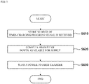
- Operation S600 is an operation of determining the amount of power supplied to the first charger.
- the charging progress signal received in operation S500 is utilized to determine the amount of power supplied to the first charger.
- operation S600 includes, as sub-operations, an operation of storing the number of times the charging progress signal is received (S610), an operation of computing the amount of power available for supply to the first charger (S620), and an operation of supplying the power to the first charger (S630).
- Operation S610 is an operation of storing the number of times the charging progress signal is received from the chargers other than the first charger in the control unit 120 of the first charger.
- the total number of charging progress signals that are received is equal to the total number of chargers that are charging electric vehicles among the chargers that are currently connected to the same power supply source 200.
- Operation S620 is an operation of computing the amount of available power available for supply to the electric vehicle 300 connected to the first charger by the control unit 120 of the first charger. In particular, operation S620 computes the amount of available power on the basis of the number of times the charging progress signal is received.
- the amount of power supplied to the first charger may be less than or equal to a value obtained by dividing the maximum amount of power that can be supplied by the power supply source 200 by one greater than the total number of received charging progress signals.
- a time division method may be applied to the method of supplying power from the power supply source 200 to each charger.
- the control unit of the first charger may perform control such that power is supplied from the power supply source 200 for 12 minutes in a 60-minute section. In any 6-minute section, the first charger receives power alone from the power supply source 200 for 1.2 minutes in the 6-minute section.
- a time interval in which each charger receives power is changed according to the number of electric vehicles currently being charged (according to the number of charging progress signals). For example, when the total number of received charging progress signals is three, the total number of electric vehicles connected in the same power supply source 200 will be four. At this time, according to the numbering order of the chargers, the four chargers may receive power alone from the power supply source 200 for a corresponding period of time, i.e., 15 minutes, based on one hour. As a result, this has the same effect as receiving a value obtained by dividing the maximum amount of power of the power supply source 200 by four.
- the control unit of each charger in use for charging may change the supply and cut-off of power at any time according to the number of charging progress signals.
- the power supply time may be changed based on one hour.
- the power may be supplied to the electric vehicles for 24 minutes, 18 minutes, 12 minutes, and 6 minutes based on one hour according to the charging start times. This will be described below.
- operation S630 proceeds.
- FIG. 10 shows another embodiment of operation S600.
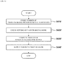
- operation S600 includes, as sub-operations, an operation of storing the number of times the charging progress signal is received (S610'), an operation of determining whether the fast charging mode is set for the first charger (S620'), an operation of computing the amount of power available for supply to the first charger (S630'), and an operation of supplying the power to the first charger (S640').
- Operation S610' is an operation of storing the number of times the charging progress signal is received from the chargers other than the first charger in the control unit 120 of the first charger and is the same as operation S610.
- Operation S620' is an operation of determining whether a user who uses the first charger has selected the fast charging mode before charging is started.
- the fast charging mode corresponds to a quick charging mode or is a charging mode that guarantees an amount of power equal to or greater than a set value. This mode is useful for users who need fast charging.
- a user can pay a higher price per kW or a higher basic usage fee than in the normal mode.
- Operation S630' is an operation of computing the amount of available power available for supply to the electric vehicle 300 connected to the first charger by the control unit 120 of the first charger and is the same as operation S620.
- Operation S640' is the same as operation S630.
- Operation S630 is an operation in which power supply to the first charger is started, and includes an operation of generating a charging start time signal when the power supply is started (S631) and an operation of the chargers other than the first charger receiving the charging start time signal (S632).
- the charging start time of the charger shared with the other chargers is the basis for setting the priority for power distribution when the power distribution is performed. Also, when a payment system is included in each charger, the payment system becomes the basis for calculating the amount of power supplied to the corresponding electric vehicle. That is, the present invention is characterized in that all operations of each charger are shared with the other chargers.
- operation S632 proceeds.
- the other chargers that have received information on the charging start time of the first charger from the first charger store the information in the control unit 120.
- FIG. 11 shows the sub-operations of operation S640' included in the embodiment of FIG. 10 .
- Operation S640' is an operation in which power supply to the first charger is started, and includes an operation of generating a charging start time signal when the power supply is started (S641'), an operation of generating a signal indicating that the fast charging mode proceeds (S642'), an operation of the chargers other than the first charger receiving the generated charging start time signal and the fast charging mode proceeding signal (S643'), and an operation of limiting the amount of power supplied to the other chargers (S644').
- Operations S641', S642', and S643' are operations for sharing important information related to the charging of the first charger with the other chargers.
- Operation S644' is an operation for limiting the number of chargers that can select the fast charging mode.
- the fast charging mode high voltage and high power are applied to charge an electric vehicle in a short time, and for this reason, the number of chargers that can simultaneously perform the fast charging mode in the same power supply source needs to be limited to a certain level.
- the selection of the fast charging mode may be partially limited or the maximum amount of supplied power supplied may be limited.
- the charger that has gone through operation S643' may store the corresponding signal in the control unit 120 and limit the amount of power available for supply on the basis of the stored information. As a result, operation S644' proceeds.
- FIG. 12 is a schematic diagram illustrating a communication process between multiple chargers when the charging of one electric vehicle 300 is completed.
- the charger and the electric vehicle are disconnected.
- the connector 110 and the electric vehicle 300 are decoupled, or electricity supply is stopped although the connector 110 and the electric vehicle 300 are coupled to each other. Meanwhile, when the wireless charging mode is applied, the wireless charging pad stops working.
- the control unit 120 of the disconnected charger When the charger and the electric vehicle are disconnected, the control unit 120 of the disconnected charger generates a charging termination signal.
- the generated charging termination signal is transmitted to all the other chargers, and a charger in use for charging may increase the amount of power supplied after the charging termination signal is received.
- the charger that had received the charging termination signal may increase the time for which power is supplied to the corresponding charger per unit time.
- FIGS. 13 and 14 A detailed flowchart in the case where the charging of the electric vehicle is terminated in the power supply method of the electric vehicle charger shown in FIG. 12 will be described through FIGS. 13 and 14 .
- FIG. 13 illustrates the overall flow of an information delivery process and a power distribution process with other chargers when the charging of one electric vehicle is completed according to an embodiment.
- Each of the operations shown in FIG. 13 may be performed by the control unit 120 and the communication unit 125 provided in each charger 100. However, the present invention is not limited thereto, and at least some or all of the operations shown in FIG. 13 may be performed by another entity.
- the charging of one charger in use for charging is terminated. All the chargers connected to the same power supply source 200 are eligible to be the charger.
- the termination of charging may be interpreted as the opposite of the connection between the charger and the electric vehicle. In general, the termination of charging means when the supply of electricity from the charger to the electric vehicle is stopped.
- control unit 120 of the charger When the charging between the charger and the electric vehicle is terminated, the control unit 120 of the charger that has stopped charging generates a charging termination signal in operation S800.
- the generated charging termination signal is transmitted to the chargers other than the charger that has stopped charging in operation S900. That is, the charging termination signal is received by the chargers other than the charger that has stopped charging.
- the chargers that have received the charging termination signal store, in the storage unit of the control unit 120, information indicating that the charging of any one charger is terminated.
- Operation S1000 is an operation of supplying excess power caused by the termination of the charging of any one charger to the other chargers that are still in use for charging, and sub-operations constituting operation S1000 will be described with reference to FIG. 14 .
- Operation S1000 includes an operation of checking a charging start time received by a third charger (S1010) and an operation of determining the amount of power distributed to the third charger (S1020).
- the third charger corresponds to one of the chargers other than the charger that has stopped charging in operation S700. That is, the "third" is only for convenience of description and is not limited to a specific charger.
- Operation S1010 is an operation of checking all the charging start time signals of the other chargers that have been received by the third charger. As the number of times multiple vehicles are charged increases, charging start time signal data of a larger number of other chargers will be stored in the control unit 120 of each charger. However, when there is a charging termination signal paired with a specific charging start time signal, the corresponding charging start time signal is excluded from the checking. The reason for checking the charging start time signal is to check information on chargers where charging is performed at the same time as soon as operation S1010 starts. When charging is already terminated, it is meaningless to check the charging start time signal data.
- Operation S1020 includes an operation of comparing the charging start time of the third charger to the charging start time signal data checked in operation S1010 (S1021), an operation of calculating the priority between the chargers in use for charging (S1022), and an operation of determining the amount of power supplied to the third charger (S1023).
- Operations S1021 and S1022 serve to compare the charging start time signals of the chargers that are in use for charging at the same time and to line up the charger with the fastest charging start time to the charger with the slowest charging start time.
- Operation S1023 is an operation of distributing the amount of power according to the calculated priority, and in an embodiment, the largest amount of power may be allocated preferentially to the charger with the fastest charging start time.
- the power supply method of the electric vehicle charger may further include an operation of transmitting a charging amount signal to one or more other chargers at every set time.
- chargers connected to one power supply source 200 can always share the charging amount information of electric vehicles connected to the chargers with each other.
- Charging amount information refers to information related to the degree to which an electric vehicle connected to a charger is charged, and information on the percentage of charging with respect to a full charging amount when the full charging amount is considered to be 100% may be defined as the charging amount information.
- the percentage of charging can be determined only in the case of a fast charger. In the case of a charger other than a fast charger, the percentage of charging may be determined through the degree to which the amount of charged power decreases as full charge is reached.
- the charging amount information may be periodically shared every set time. That is, each charger periodically transmits the charging amount information to chargers other than the corresponding charger and stores the charging amount information of the other chargers in the control unit 120 when the charging amount information is received. By updating the charging amount information in real time, the basis for efficiently changing the amount of supplied power is established.
- operation S1000 may include an operation of checking the charging amount of an electric vehicle connected to the third charger, an operation of comparing the charging amount of the electric vehicle connected to the third charger to a prereceived charging amount signal, an operation of calculating priority, and an operation of distributing the amount of power according to the calculated priority. All of the above operations may be performed by the control unit 120 of the third charger.
- the charger connected to the electric vehicle with the smaller charging amount may be controlled to have a large time ratio for power supplied to the connected electric vehicle per unit time.
- At least one of the multiple chargers may be provided to enable communication with an external server.
- a local area network such as WiFi, 3G, and LTE may be utilized for the communication with the external server.
- a charger reservation system or a payment system may be additionally applied through an application, and it is possible to check the status of the chargers without visiting the site in person.
- At least one of the chargers 100 of FIGS. 4 to 7 may be the movable charger 100' of FIG. 2 .
- the movable charger 100' may be fully charged in the early morning hours when charging demand is low.
- the fully charged movable charger 100' may serve to assist the power supply source 200 during daytime hours or evening hours after work when charging demand is high.
- some of the chargers 100 may receive power from the fully charged movable charger 100'.
- the level of the auxiliary role of the movable charger 100' may be set differently depending on the time period.
- the movable charger 100' may be set to supply the allowable maximum amount of power to other chargers in a time period when the amount of required power is large, and the movable charger 100' may be set to supply the minimum amount of power to other chargers in a time period when the amount of required power is small.
Landscapes
- Engineering & Computer Science (AREA)
- Power Engineering (AREA)
- Transportation (AREA)
- Mechanical Engineering (AREA)
- Life Sciences & Earth Sciences (AREA)
- Sustainable Development (AREA)
- Sustainable Energy (AREA)
- General Engineering & Computer Science (AREA)
- Physics & Mathematics (AREA)
- General Physics & Mathematics (AREA)
- Automation & Control Theory (AREA)
- Charge And Discharge Circuits For Batteries Or The Like (AREA)
- Electric Propulsion And Braking For Vehicles (AREA)
Abstract
Description
- The present invention relates to a power supply method of an electric vehicle charger, and more particularly, to a power supply method of a charger for an electric vehicle that can efficiently control power distribution through communication between chargers connected to the same power supply source (power grid) without an external communication function.
- An electric vehicle (EV) is future convergence technology that is receiving attention and investment from governments and companies around the world along with the trend of a global green growth policy. Accordingly, the demand tendency of the automobile industry market is quickly changing from conventional oil-based vehicles to electric vehicles.
- Along with the increase in demand for electric vehicles, technology development not only for electric vehicles but also for infrastructure construction (charging devices, power supply grids, etc.) for smooth use of electric vehicles is being actively conducted.
- However, since the infrastructure construction according to the supply of electric vehicles is relatively incomplete, methods and technologies for charging a large number of electric vehicles are being developed recently. In particular, in the case of an office building or an apartment house, the excess of power reception capacity due to the addition of charging infrastructure for electric vehicles in electric power management may affect the daily power used by residents or cause a large-scale power shortage.
- As related art for solving these problems, a conventional technique shown in
FIG. 1 will be described. - In order to charge multiple electric vehicles in the related art, a
power supply source 10 includes amain charger 30 andmultiple sub-chargers 40 directly controlled by themain charger 30. Themain charger 30 directly controls the amount of power supplied to thesub-chargers 40 and is in charge of communication with anexternal server 20. - Specifically, the
main charger 30 includes ameasurement unit 31 for monitoring the amount of power used by thesub-chargers 40 and a unit charging amount, apower supply unit 32, acommunication unit 33 for communicating with theserver 20 and thesub-chargers 40, and acontrol unit 34 for controlling the number of sub-chargers to be operated or controlling a communication function, and thesub-charger 40 includes anoutlet 41 built in the apparatus together with a fixed wiring and aconnector 42 to be docked with an electric vehicle charging unit. - In the case of this conventional centralized multi-charging method, when the main charger fails, the sub-chargers cannot operate, the installation and maintenance costs of the main charger are quite large, and communication between the sub-chargers is impossible. Thus, immediate power distribution is difficult.
- The present invention has been created to solve the above problems and is directed to providing a power supply method of an electric vehicle charger that, by only using chargers that do not have a function of communicating with the outside, can efficiently distribute the amount of power to the chargers without a main charger.
- Specifically, the present invention provides a power supply method of a charger for an electric vehicle capable of efficiently distributing the amount of electric power supplied by each charger to an electric vehicle within the maximum amount of electric power by enabling mutual communication between chargers connected to the same electric power supply source.
- Also, provided is a power supply method for a charger for an electric vehicle that can lower overall charger installation costs by not installing a separate main charger.
- The technical objects of the present invention are not limited to those described above, and other technical objects that are not described herein will be apparently understood by those skilled in the art from the following description.
- To achieve the above objects, a power supply method of an electric vehicle charger in which multiple chargers are connected to the same power supply source may include operations of: allowing an electric vehicle to be connected to a first charger, generating a charging start signal from the first charger, receiving, by one or more other chargers, the charging start signal, generating a charging state signal from the other chargers, receiving, by the first charger, the charging state signal; and determining the amount of supplied power of the first charger. Accordingly, by only using chargers that do not have a function of communicating with the outside, it is possible to efficiently distribute the amount of power to the chargers without a main charger.
- Also, in an embodiment of the present invention, the operation of generating a charging state signal from the other chargers may include operations of determining whether an electric vehicle is connected to a second charger, generating a charging progress signal or a charging standby signal from the second charger, and transmitting the generated signal to the first charger, and the charging progress signal may be a signal generated when the electric vehicle is being charged, and the charging standby signal may be a signal generated when the second charger is on standby. Accordingly, it is possible for the chargers to share whether each charger is in use for charging with each other.
- Also, in an embodiment of the present invention, the operation of generating a charging state signal may include operations of determining whether an electric vehicle is connected to a second charger and generating a charging progress signal from the second charger, the operation of receiving, by the first charger, the charging state signal may include an operation of checking whether the charging state signal is received within a set time, and when the charging state signal is not transmitted within the set time, the first charger determines that the second charger is on standby. Accordingly, it is possible for the chargers to share whether each charger is on standby with each other.
- Also, in an embodiment of the present invention, the operation of determining the amount of supplied power of the first charger may include operations of storing the number of times the charging progress signal is received, computing the amount of power available for supply to the first charger, and supplying the power to the first charger, and the amount of power supplied to the first charger may reflect the number of times the charging progress signal is received. Accordingly, by only using chargers that do not have a function of communicating with the outside, it is possible to efficiently distribute the amount of power to the chargers without a main charger.
- Also, in an embodiment of the present invention, the amount of power supplied to the first charger may be less than or equal to a value obtained by dividing the maximum amount of power by one greater than the number of times the charging progress signal is received. Accordingly, when two or more vehicles are charged through a charger in the same power supply source on the basis of the shared state of each charger, it is possible to properly distribute the amount of power.
- Also, in an embodiment of the present invention, the operation of determining the amount of supplied power of the first charger may further include an operation of determining whether a fast charging mode is set, and when the fast charging mode is set, the first charger may receive more than a set amount of power from the power supply source. Accordingly, by allowing a user to set the fast charging mode according to his or her need, it is possible to increase charging efficiency and increase the profitability of charger providers.
- Also, in an embodiment of the present invention, the operation of supplying the power to the first charger may include operations of generating a charging start time signal, generating a fast charging mode progress signal, and receiving, by the other chargers, the charging start time signal and the fast charging mode progress signal, and when the other chargers receive the fast charging mode progress signal, the maximum amount of power supplied from the power supply source is limited. Accordingly, it is possible to limit the number of chargers that can select the fast charging mode.
- Also, in an embodiment of the present invention, the operation of supplying the power to the first charger may include operations of generating a charging start time signal and receiving, by the other chargers, the charging start time signal. Accordingly, by sharing a charging start time between chargers, it is possible to set a criterion that can be used for power distribution.
- Also, in an embodiment of the present invention, the method may further include operations of terminating the charging of any one charger, generating a charging termination signal from the charger, receiving, by the other chargers, the charging termination signal; and determining the amount of supplied power of the other chargers. Accordingly, it is possible to share whether the charging of each charger is terminated.
- Also, in an embodiment of the present invention, the operation of determining the amount of supplied power of the other chargers may include operations of checking a charging start time signal received by a third charger and determining the amount of power distributed to the third charger. Accordingly, based on the shared state of each charger, it is possible to supply more idle power to chargers that are in use for charging.
- Also, in an embodiment of the present invention, the operation of determining the amount of power distributed to the third charger may include operations of comparing a charging start time of the third charger to the received charging start time signal and calculating priority, and the amount of distributed power may be determined according to the calculated priority. By giving priority to an electric vehicle that starts charging first, it is possible to supply electric power quickly and efficiently within a limited amount of power.
- Also, in an embodiment of the present invention, a power supply system of an electric vehicle charger includes multiple chargers connected to the same power supply source and configured to communicate with each other, and when an electric vehicle is connected to one charger, a charging start signal is transmitted from the charger to which the electric vehicle is connected to one or more other chargers, a charging state signal is transmitted from the other chargers to the charger to which the electric vehicle is connected, and the amount of power supplied to the charger to which the electric vehicle is connected is determined according to the charging state signal. Accordingly, by only using chargers that do not have a function of communicating with the outside, it is possible to efficiently distribute the amount of power to the chargers.
- Also, in an embodiment of the present invention, each of the chargers may include a connector connected to an electric vehicle and configured to supply power, a control unit configured to control the amount of power supplied to the connector, the control unit including a communication unit in charge of communication with other chargers, and a connection unit connected to a power supply source and configured to perform a fast charging mode or a slow charging mode according to a signal of the control unit.
- Also, in an embodiment of the present invention, at least one of the multiple chargers may be capable of communicating with an external server. Accordingly, by setting one charger capable of communicating with an external server for payment, it is possible to help smooth payment of the other chargers.
- Also, in an embodiment of the present invention, at least one of the multiple chargers may be a movable charger including a movable means for moving to a location where an electric vehicle is parked.
- According to the disclosed embodiment of the present invention, by only using chargers that do not have a function of communicating with the outside, it is possible to efficiently distribute the amount of power to the chargers.
- Also, it is possible for the chargers to share the state of each charger with each other.
- Also, it is possible to shorten a charging time by efficiently distributing the limited maximum amount of power to each charger.
- Also, it is possible to reduce total charger installation costs by omitting a component such as the conventional main charger.
- The effects of the present invention are not limited to those described above, and other effects that are not described herein will be apparently understood by those skilled in the art from the following description.
-
-
FIG. 1 is a diagram schematically illustrating a conventional power distribution system composed of a main charger and multiple sub-chargers. -
FIG. 2 is a diagram illustrating multiple chargers and an electric vehicle connected thereto according to an embodiment. -
FIG. 3 is a diagram illustrating a relationship between components constituting each charger according to an embodiment. -
FIGS. 4 and5 illustrate a process of mutual communication between chargers when an electric vehicle is connected. -
FIGS. 6 and7 are diagrams illustrating a process in which communication occurs between chargers when a new electric vehicle attempts charging while at least one electric vehicle is being charged. -
FIG. 8 is a flowchart illustrating a power supply method for charging an electric vehicle when the charging of an electric vehicle starts according to an embodiment. -
FIG. 9 is a flowchart illustrating a method of calculating the amount of power supplied to each charger. -
FIG. 10 is a flowchart illustrating a method of calculating the amount of power supplied to each charger according to another embodiment. -
FIG. 11 is a flowchart illustrating a method of calculating the amount of power supplied to each charger when a fast charging mode is applied. -
FIG. 12 illustrates an aspect in which communication occurs between chargers when the charging of an electric vehicle is terminated. -
FIG. 13 is a diagram illustrating a method in which power is supplied when the charging of an electric vehicle is terminated according to an embodiment. -
FIG. 14 is a flowchart illustrating a method of supplying an amount of power by utilizing a charging start time. - Advantages and features of the present invention and implementation methods thereof will be clarified through the following embodiments described in detail with reference to the accompanying drawings. The present invention may, however, be embodied in many different forms and should not be construed as being limited to the embodiments set forth herein. Rather, these embodiments are provided so that this disclosure will be thorough and complete and will fully convey the concept of the invention to those skilled in the art, and the present invention will only be defined by the appended claims.
- The terminology used herein is for the purpose of describing particular embodiments only and is not intended to be limiting of the invention. Herein, the singular shall be construed to include the plural, unless the context clearly indicates otherwise. The terms "comprises" and/or "comprising" used herein specify the presence of stated elements but do not preclude the presence or addition of one or more other elements. Like reference numerals refer to like elements throughout the specification, and the term "and/or" includes any and all combinations of one or more of the associated listed items. It will be also understood that, although the terms first, second, etc. may be used herein to describe various elements, these elements should not be limited by these terms. These terms are only used to distinguish one element from another. Thus, a first element could be named a second element without departing from the technical spirit of the present invention.
- Unless otherwise defined, all terms (including technical and scientific terms) used herein have the same meaning as commonly understood by one of ordinary skill in the art to which this invention belongs. It will be further understood that terms, such as those defined in commonly used dictionaries, should be interpreted as having a meaning that is consistent with their meaning in the context of the relevant art and will not be interpreted in an idealized or overly formal sense unless expressly so defined herein.
- As used herein, the term "unit" or "module" refers to a software element or a hardware element such as a field-programmable gate array (FPGA) or an application-specific integrated circuit (ASIC), and a "unit" or "module" performs any role. However, a "unit" or "module" is not limited to software or hardware. A "unit" or "module" may be configured to reside in an addressable storage medium or to execute one or more processors. Therefore, for example, a "unit" or "module" includes elements, such as software elements, object-oriented software elements, class elements, and task elements, processes, functions, attributes, procedures, subroutines, segments of program code, drivers, firmware, microcode, circuits, data, database, data structures, tables, arrays, and variables. Furthermore, functions provided in elements and "units" or "modules" may be combined into as a smaller number of elements and "units" or further divided into additional elements and "units."
- Herein, a computer refers to any kind of hardware device including at least one processor and may be understood as encompassing software configurations operating in corresponding hardware devices depending on the embodiment. For example, a computer may be understood as including smartphones, tablet PCs, desktops, notebooks, and user clients and applications running in such devices. However, the present invention is not limited thereto.
- Hereinafter, the embodiments of the present invention will be described in detail with reference to the accompanying drawings.
- Herein, each operation will be described as being performed by a computer, but the subject of each operation is not limited thereto, and at least some of the operations may be performed in different devices depending on the embodiment.
- In an embodiment of the present invention, an electric vehicle charging system may be defined as a system that basically charges a battery mounted in an electric vehicle by using electric power of an energy storage device or a commercial power supply source. Such an electric vehicle charging system may have various forms depending on the type of electric vehicle. For example, the electric vehicle charging system may include a cable-based conductive charging system or a non-contact wireless power transmission system.
- Also, in an embodiment of the present invention, an electric vehicle (EV) may be referred to as an electric car, an electric automobile, an electric road vehicle (ERV), a plugin vehicle (PV or xEV), and the like, and a power supply source may include residential or public electric service or a generator that uses vehicle-mounted fuel.
- Also, in an embodiment of the present invention, the connection between an electric vehicle and a charger may refer to a procedure in which a connector (or wireless charging device) disposed to transmit power is associated with the electric vehicle. Specifically, the procedure includes a process of exchanging information necessary for command and control communication, control, and termination between the electric vehicle and the charger.
- Meanwhile, in an embodiment, the charger includes not only wired charging but also wireless charging. A wireless power charging system may refer to a system for control between a GA and a VA including wireless power transmission and alignment and communication. Wireless power transfer may refer to transferring electrical power from an alternating current (AC) power supply network to an electric vehicle through contactless means.
- Also, according to an embodiment of the present invention, chargers can communicate with each other. Various methods may be applied for communication between chargers. For example, Bluetooth that communicates within a short distance of less than 10 m, a beacon that communicates within a short distance of less than 70 m, Addictive Links Online Hawaii Area (ALOHA) corresponding to a contention-type multiple access protocol that randomly accesses a common transmission channel without central control, Wi-Fi, PLC communication, and P2P communication may be applied.
- Also, the charger according to an embodiment of the present invention may be a charger that corresponds to one of a fast charger or a slow charger or a charger to which the two modes are applied.
- Hereinafter, preferred embodiments of the present invention will be described in detail with reference to the accompanying drawings.
-
FIG. 2 is a conceptual diagram illustrating a power distribution method of an electric vehicle charger according to an embodiment of the present invention. - Referring to
FIG. 2 ,multiple chargers 100 according to an embodiment of the present invention are connected to the samepower supply source 200. Thepower supply source 200 has a limit to the power available for supply, and this limit of power may be defined as the maximum amount of power. In the case of a building, the maximum power available for supply to one building may be defined as the maximum amount of power. - Electricity from the
power supply source 200 is supplied to thecharger 100 through adistribution box 210, ameter 220, and apower supply unit 230. Thedistribution box 210 is an element that has a function of receiving electricity from the outside, supplying electricity to thepower supply unit 230, and shutting off electricity in case of failure. Themeter 220 is a meter that measures and records the total amount of power used for a certain period of time. Thepower supply unit 230 has the same configuration as an outlet and is an element to which thecharger 100 is directly connected to receive power. Meanwhile, the electricity of thepower supply source 200 may be directly connected to chargers through wires without thepower supply unit 230. Depending on the installation environment or the nature of the charger, thepower supply unit 230 may be selectively applied. -
Multiple chargers 100 may be installed at onepower supply source 200, and the number of installed chargers may be limited by the maximum amount of power that can be supplied by thepower supply source 200. Themultiple chargers 100 connected to onepower supply source 200 may be installed in a mixture of various types. - As shown in
FIG. 2 , some of the multiple chargers may bestationary chargers 100, and the others may be movable chargers 100'. Thestationary charger 100 is directly connected to thepower supply unit 230, and for charging, anelectric vehicle 300 should be driven in front of thecharger 100. - The movable charger 100' includes a power connection unit 101' coupled to the
power supply unit 230 and a moving means that can move to where theelectric vehicle 300 is parked. In the charging standby state, the movable charger 100' is connected to the power connection unit 101' to receive electricity from thepower supply source 200. When a charging request is received through an application or various communication means, the movable charger 100' moves to where theelectric vehicle 300 is located according to the charging request signal and performs the charging of theelectric vehicle 300. - Meanwhile, according to an embodiment of the present invention, at least one of a wired charging method and a wireless charging method may be applied to the
multiple chargers 100, and the wired and/or wireless charging methods may be applied to both thestationary charger 100 and the movable charger 100'. - Each
charger 100 according to an embodiment of the present invention includes aconnector 110 directly connected to theelectric vehicle 300 to supply power, acontrol unit 120 for controlling the amount of power supplied to theconnector 110, and aconnection unit 130 connected to thepower supply unit 230. When thecharger 100 adopts a wireless method or additionally includes a wireless method, thecharger 100 may include a wireless charging panel. However, there are also embodiments in which theconnection unit 130 is not provided together with thepower supply unit 230. According to the installation environment of the charger and the specifications of the charger, theconnection unit 130 may be selectively applied. - The
electric vehicle 300 may include acommunication controller 310 for communicating with other external devices, and thecommunication controller 310 is an element that can communicate with theconnector 110 and a user terminal. Generally, the communication between theelectric vehicle 300 and the charger may be made only when the charger is a DC fast charger. On the other hand, in the case of a slow charger, it is common that the communication between the charger and theelectric vehicle 300 is not made. - Meanwhile, referring to
FIG. 2 , it can be seen that a main charger or a central control unit for collectively controlling themultiple chargers 100 is not provided. It is possible to control the amount of power supplied to each charger only with general chargers without a separate central control unit or main charger. Specifically, themultiple chargers 100 are provided to communicate with each other, and the detailed configuration of thecharger 100 will be described with reference toFIG. 3 . -
FIG. 3 is a schematic diagram of detailed elements constituting eachcharger 100. - The
connector 110 includes afirst connector 111 and asecond connector 112 which are directly connected to theelectric vehicle 300 to supply power. - The
first connector 111 is a charging terminal for supporting charging in a combo 1 method and is formed of a combination of a single-phase AC slow charging socket and a DC fast charging socket. This is mainly used in the United States. - The
second connector 112 is a charging terminal for supporting charging in a combo 2 method and is formed of a combination of a three-phase AC slow charging socket and a DC fast charging socket. This is mainly used in Europe. - Advantageously, the
second connector 112 can be applied to more various situations and vehicles than thefirst connector 111 because there are various charging methods for supporting thesecond connector 112, such as DC single charging, DC and three-phase AC power, DC and single-phase AC power, and three-phase AC single charging. - Meanwhile, the scope of the present invention for the
connector 110 is not limited thereto. At least one of thefirst connector 111 and thesecond connector 112 may be applied as theconnector 110, and another type of connector, for example, a J1772 slow connector, may be applied. - In another embodiment, the charger may not be provided with a connector and a cable. In this case, only the socket is installed in the charger, and the connector or cable may be separately purchased and used by a user who wants to use the charger.
- The
control unit 120 may be composed of one or more processors and memories or may be composed of a computer. Thecontrol unit 120 is in charge of communication with thecharger 100 connected to the samepower supply source 200 and the control of the amount of power supplied to the connectedelectric vehicle 300. - Specifically, the
control unit 120 may include aninput unit 121, adisplay unit 122, arelay unit 123, apayment unit 124, and acommunication unit 125. However, some of the above elements may be omitted, and a separate element may be further added if necessary. The description of the configuration of thecontrol unit 120 is for explaining the operating aspect of thecharger 100 according to an embodiment of the present invention. - The
input unit 121 includes multiple keys for inputting charging request information, and data input to the keys is delivered to thecontrol unit 120. For example, through the key input, it is possible to reserve charging, immediately start and terminate charging, input a charging reservation time, input numeric information, and input user information and vehicle information. Meanwhile, theinput unit 121 may be replaced with a touch unit that is displayed on a display instead of a physical key. However, a charger according to another embodiment does not include theinput unit 121. Various methods for controlling the charger may be applied without aseparate input unit 121. - The
display unit 122 may be configured by thecontrol unit 120 to display information such as operation state information on whether thecharger 100 is in use for charging or on standby, the price per watt (W) or kilowatt (kW) of charging power, the remaining amount of battery power, the full amount of battery power, and the time required for fully charging. However, thedisplay unit 122 may not be provided depending on thecharger 100. - The
relay unit 123 includes a relay and is configured to connect the output power of aconverter 132 to thefirst connector 111 or thesecond connector 112 under the control of thecontrol unit 120. The relay may be implemented using a device such as an insulated-gate bipolar transistor (IGBT). When there is only one combo constituting theconnector 110, the configuration of the relay unit 150 may be omitted. - The
payment unit 124 is a device such as a card reader, a cash counting device, and a universal subscriber identity module (USIM) reader and is configured to provide payment information about the charging power used by a user to thecontrol unit 120. However, themultiple chargers 100 according to an embodiment of the present invention may not include thepayment unit 124 except for any one charger. The other chargers that do not include thepayment unit 124 may transmit information on the charging power used by the user to thecharger 100 including thepayment unit 124. Thecharger 100 including thepayment unit 124 may further include a separate communication device capable of communicating with an external server, which will be described below. - However, according to another embodiment of the present invention, the
multiple chargers 100 do not include thepayment unit 124. Information on charging power that is used by the user and measured by eachcharger 100 may be connected to the user's payment means through any onecharger 100 connected to the external server. The user's payment means may be card information registered in the application or account information preregistered by the user. - The
communication unit 125 is an element that enables communication between themultiple chargers 100 and can share information on eachcharger 100 using a power line communication (PLC) method or a peer-to-peer (P2P) communication method. In addition to PLC communication or P2P communication, pulse width modulation) (PWM) communication, controller area network (CAN) communication, media oriented systems transport (MOST) communication, local interconnect network (LIN) communication, Bluetooth communication, ALOHA communication, and beacon communication., etc. may be used. - The
communication unit 125 is used to transmit or receive information on whether eachcharger 100 is in use for charging or on standby, information on whether an electric vehicle is connected, information on whether charging is terminated, information on the amount of power used when each electric vehicle is charged and the amount of power available for supply, etc. - Also, the
communication unit 125 may be used to transmit or receive other charging-related information. For example, thecommunication unit 125 may be involved in the operation of thefirst connector 111 or thesecond connector 112 according to a signal from thecontrol unit 120 and may also communicate with the parkedelectric vehicle 300. - The
connection unit 130 is composed of aconnection cord 131 connected to thepower supply unit 230 and aconverter 132 configured to perform voltage conversion. - The
converter 132 may include both an AC/DC converter function and a DC/DC converter function and may supply suitable power depending on whether a charging mode selected by a user is a fast mode or a slow mode, according to the type of combo in which the electric vehicle is connected. - In an embodiment of the present invention, the
converter 132 may adjust the amount of power supplied to the electric vehicle connected according to the result of communication between themultiple chargers 100 by thecommunication unit 125. The amount of power allocated to each charger is determined by the communication between themultiple chargers 100, and a detailed algorithm for this will be described below. -
FIGS. 4 to 7 schematically illustrate and simplify a mutual communication process between themultiple chargers 100 when an electric vehicle that requires charging is connected to any one of themultiple chargers 100 connected to the samepower supply source 200. -
FIGS. 4 and5 schematically illustrate a mutual communication process between chargers when oneelectric vehicle 300 is connected to any one charger whilemultiple chargers 100 connected to the samepower supply source 200 are on standby. -
FIGS. 6 and7 schematically illustrate a mutual communication process between multiple chargers connected to the samepower supply source 200 when oneelectric vehicle 300 is connected to a charger on standby while at least one of thechargers 100 is in use for charging. - According to
FIG. 4 , it can be seen that when anelectric vehicle 300 is connected to acharger 100 on standby, a charging start signal is generated from thecharger 100 connected to theelectric vehicle 300. Theelectric vehicle 300 being "connected" to thecharger 100 is interpreted not only to mean that theelectric vehicle 300 and thecharger 100 are directly coupled for charging but also to include a state in which theelectric vehicle 300 and thecharger 100 are scheduled to be coupled for charging. - When the
charger 100 on standby is connected to theelectric vehicle 300, thecharger 100 connected to the electric vehicle transmits a charging start signal to theother chargers 100 connected to the samepower supply source 200. - The charging start signal is a signal generated when the
electric vehicle 300 is connected to thecharger 100. For example, the charging start signal is generated when theelectric vehicle 300 is connected to theconnector 110, when thecommunication controller 310 of theelectric vehicle 300 is connected to thecommunication unit 125, or when theelectric vehicle 300 is highly likely to be coupled to thecharger 100. - Specifically, when the
electric vehicle 300 is connected to theconnector 110, theconnector 110 may transmit a connection signal to thecontrol unit 120 through therelay unit 123, and upon receiving the connection signal, thecontrol unit 120 may transmit the charging start signal to the other chargers through thecommunication unit 125. When there is only one connector type for theconnector 110, theconnector 110 may directly transmit a connection signal to thecontrol unit 120. - Various communication methods may be applied to the
multiple chargers 100. In an embodiment of the present invention, a PLC communication method or a P2P communication method may be applied to the chargers, and both of the two communication methods may be applied. The PLC communication method and the P2P communication method are general techniques known to those skilled in the art, and thus a detailed description thereof will be omitted. - In addition to the PLC communication method or the P2P communication method, PWM communication, CAN communication, MOST communication, local interconnect network (LIN) communication, Bluetooth communication, ALOHA communication, beacon communication, or the like may be used for the chargers.
-
FIG. 5 shows that the other chargers that have received the charging start signal from thecharger 100 to which theelectric vehicle 300 is connected transmit a charging state signal. The other chargers transmit the charging state signal to the charger where the charging start signal is generated. - The charging state signal may include a charging progress signal and a charging standby signal. The charging progress signal means that charging is in progress, and the charging standby signal means that charging is not in progress.
- Specifically, the charging state signal is a signal that contains information on whether the
connector 110 is connected to theelectric vehicle 300 and whether charging is in progress in the case of wireless charging. - As shown in
FIG. 6 , when a newelectric vehicle 300 is connected while one or moreelectric vehicles 300 are being charged, thecharger 100 to which the newelectric vehicle 300 is connected generates a charging start signal and transmits the generated charging start signal to the other chargers. - As shown in
FIG. 7 , acharger 100 that is in use for charging may generate a charging progress signal and transmit the generated charging progress signal, and acharger 100 that is not in use for charging may generate a charging standby signal and transmit the charging standby signal to the charger where the charging progress signal is generated or may not transmit any signal. - A detailed flowchart of the power supply method of the electric vehicle charger shown in
FIGS. 4 to 7 will be described with reference toFIGS. 8 to 11 . -
FIG. 8 illustrates the overall flow of a method in which an electric vehicle charger supplies power when a new electric vehicle attempts charging from the charger. - Each of the operations shown in
FIG. 8 may be performed by thecontrol unit 120 and thecommunication unit 125 provided in eachcharger 100. However, the present invention is not limited thereto, and at least some or all of the operations shown inFIG. 8 may be performed by another entity. - In operation S100, a first charger among
multiple chargers 100 is connected to anelectric vehicle 300. The first charger corresponds to an arbitrary charger and even though the charger is referred to as the first charger, it does not have a special state or function. The meaning of theelectric vehicle 300 being connected to the first charger has the same meaning as described above. - When the connection between the first charger and the electric vehicle is completed, in operation S200, the
control unit 120 of the first charger generates a charging start signal. For example, thecontrol unit 120 receives a charging start signal from a connector or a wireless charging pad (not shown) or generates a charging start signal when charging is confirmed in the near future. - The charging start signal generated by the first charger is transmitted to the chargers other than the first charger in operation S300. That is, the charging start signal is received by the chargers other than the first charger. Each of the chargers that have received the charging start signal stores information indicating that the charging of the first charger is started in a storage unit of a
control unit 120 included in the corresponding charger. - In operation S400, the chargers that receive the charging start signal generate a charging state signal. The charging state signal contains information on whether the chargers that have received the charging start signal are charging other
electric vehicles 300 at the time when the chargers received the charging start signal. - Specifically, the charging state signal includes a charging progress signal and a charging standby signal. The charging progress signal means that the charging of the electric vehicle is in progress, and the charging standby signal means that the electric vehicle is not being charged.
- Meanwhile, according to another embodiment, the charging state signal may include only the charging progress signal.
- In operation S500, the first charger receives the charging state signals generated by the other chargers. The
control unit 120 of the first charger may determine whether the charging of the chargers is in progress on the basis of the received charging state signal. Information on whether the charging of the chargers is in progress is stored in thecontrol unit 120 of the first charger. - When the charging state signal includes both the charging progress signal and the charging standby signal, the first charger determines the states of the other chargers according to the types of the received signals and stores information on the states of the chargers. On the other hand, when the charging state signal includes only the charging progress signal, whether each of the chargers is on standby for charging may be determined as follows.
- Operation S300 further includes an operation of determining whether the charging state signal is received within a set time (S310). When the chargers other than the first charger are in use for charging, the chargers in use for charging transmits the charging state signal to the first charger within the set time. When the charging progress signal is not received within the set time, the chargers that do not transmit the signal may be determined to be on standby for charging by the
control unit 120 of the first charger. - When the reception of the charging state signal by the first charger is completed and the determination of the current states of the other chargers is completed, operation S600 proceeds, and operation S600 will be described in detail with reference to
FIG. 9 . - Operation S600 is an operation of determining the amount of power supplied to the first charger. The charging progress signal received in operation S500 is utilized to determine the amount of power supplied to the first charger.
- In detail, operation S600 includes, as sub-operations, an operation of storing the number of times the charging progress signal is received (S610), an operation of computing the amount of power available for supply to the first charger (S620), and an operation of supplying the power to the first charger (S630).
- Operation S610 is an operation of storing the number of times the charging progress signal is received from the chargers other than the first charger in the
control unit 120 of the first charger. The total number of charging progress signals that are received is equal to the total number of chargers that are charging electric vehicles among the chargers that are currently connected to the samepower supply source 200. By determining the total number of chargers in use for charging, it is possible to check the maximum amount of power available for supply to the first charger or the range of the amount of power available for supply. - Operation S620 is an operation of computing the amount of available power available for supply to the
electric vehicle 300 connected to the first charger by thecontrol unit 120 of the first charger. In particular, operation S620 computes the amount of available power on the basis of the number of times the charging progress signal is received. - For example, the amount of power supplied to the first charger may be less than or equal to a value obtained by dividing the maximum amount of power that can be supplied by the
power supply source 200 by one greater than the total number of received charging progress signals. When the maximum amount of power that can be supplied by thepower supply source 200 is 10 kWh and the total number of received charging progress signals is 4, the maximum amount of power supplied to the first charger will be less than or equal to 10/5 = 2 kWh. - Meanwhile, according to an embodiment of the present invention, a time division method may be applied to the method of supplying power from the
power supply source 200 to each charger. As in the above example, when the maximum amount of power that can be supplied by thepower supply source 200 is 10 kWh and the amount of power available for supply to the first charger is 2 kWh, the control unit of the first charger may perform control such that power is supplied from thepower supply source 200 for 12 minutes in a 60-minute section. In any 6-minute section, the first charger receives power alone from thepower supply source 200 for 1.2 minutes in the 6-minute section. - When the time division method is applied, a time interval in which each charger receives power is changed according to the number of electric vehicles currently being charged (according to the number of charging progress signals). For example, when the total number of received charging progress signals is three, the total number of electric vehicles connected in the same
power supply source 200 will be four. At this time, according to the numbering order of the chargers, the four chargers may receive power alone from thepower supply source 200 for a corresponding period of time, i.e., 15 minutes, based on one hour. As a result, this has the same effect as receiving a value obtained by dividing the maximum amount of power of thepower supply source 200 by four. The control unit of each charger in use for charging may change the supply and cut-off of power at any time according to the number of charging progress signals. - Meanwhile, when a charger that starts charging first is weighted or when a user who applies for fast charging is weighted, the power supply time may be changed based on one hour. In the above example, the power may be supplied to the electric vehicles for 24 minutes, 18 minutes, 12 minutes, and 6 minutes based on one hour according to the charging start times. This will be described below.
- When the amount of power available for supply is determined, operation S630 proceeds.
- Meanwhile,
FIG. 10 shows another embodiment of operation S600. - In detail, according to another embodiment, operation S600 includes, as sub-operations, an operation of storing the number of times the charging progress signal is received (S610'), an operation of determining whether the fast charging mode is set for the first charger (S620'), an operation of computing the amount of power available for supply to the first charger (S630'), and an operation of supplying the power to the first charger (S640').
- Operation S610' is an operation of storing the number of times the charging progress signal is received from the chargers other than the first charger in the
control unit 120 of the first charger and is the same as operation S610. - Operation S620' is an operation of determining whether a user who uses the first charger has selected the fast charging mode before charging is started. The fast charging mode corresponds to a quick charging mode or is a charging mode that guarantees an amount of power equal to or greater than a set value. This mode is useful for users who need fast charging. When the fast charging mode is selected, a user can pay a higher price per kW or a higher basic usage fee than in the normal mode.
- Operation S630' is an operation of computing the amount of available power available for supply to the
electric vehicle 300 connected to the first charger by thecontrol unit 120 of the first charger and is the same as operation S620. Operation S640' is the same as operation S630. - Operation S630 is an operation in which power supply to the first charger is started, and includes an operation of generating a charging start time signal when the power supply is started (S631) and an operation of the chargers other than the first charger receiving the charging start time signal (S632).
- In operation S631, the charging start time of the charger shared with the other chargers is the basis for setting the priority for power distribution when the power distribution is performed. Also, when a payment system is included in each charger, the payment system becomes the basis for calculating the amount of power supplied to the corresponding electric vehicle. That is, the present invention is characterized in that all operations of each charger are shared with the other chargers.
- In order to share the charging start time of the first charger with the other chargers, operation S632 proceeds. The other chargers that have received information on the charging start time of the first charger from the first charger store the information in the
control unit 120. -
FIG. 11 shows the sub-operations of operation S640' included in the embodiment ofFIG. 10 . - Operation S640' is an operation in which power supply to the first charger is started, and includes an operation of generating a charging start time signal when the power supply is started (S641'), an operation of generating a signal indicating that the fast charging mode proceeds (S642'), an operation of the chargers other than the first charger receiving the generated charging start time signal and the fast charging mode proceeding signal (S643'), and an operation of limiting the amount of power supplied to the other chargers (S644').
- Operations S641', S642', and S643' are operations for sharing important information related to the charging of the first charger with the other chargers.
- Operation S644' is an operation for limiting the number of chargers that can select the fast charging mode. In the fast charging mode, high voltage and high power are applied to charge an electric vehicle in a short time, and for this reason, the number of chargers that can simultaneously perform the fast charging mode in the same power supply source needs to be limited to a certain level.
- Accordingly, for the other chargers that have received the signal indicating that the fast charging mode of the first charger is in progress, the selection of the fast charging mode may be partially limited or the maximum amount of supplied power supplied may be limited.
- The charger that has gone through operation S643' may store the corresponding signal in the
control unit 120 and limit the amount of power available for supply on the basis of the stored information. As a result, operation S644' proceeds. - By multiple chargers immediately sharing all charging-related information such as charging start information, charging state information, charging start time information, and fast charging mode progress information, it is possible to efficiently distribute the amount of power to each charger within the maximum amount of power provided by the same
power supply source 200 even without a main charger operatively associated with an external server. Also, even when one charger fails, the other chargers can charge electric vehicles without any problem. Also, predetermined chargers may be additionally installed when the maximum amount of power supplied by thepower supply source 200 increases, and the installation is terminated when only the minimum communication between chargers is established. Thus, advantageously, it is possible to significantly reduce installation costs and lower repair costs. -
FIG. 12 is a schematic diagram illustrating a communication process between multiple chargers when the charging of oneelectric vehicle 300 is completed. - When the charging of an electric vehicle connected to one charger is completed, the charger and the electric vehicle are disconnected. In an embodiment of the present invention, the
connector 110 and theelectric vehicle 300 are decoupled, or electricity supply is stopped although theconnector 110 and theelectric vehicle 300 are coupled to each other. Meanwhile, when the wireless charging mode is applied, the wireless charging pad stops working. - When the charger and the electric vehicle are disconnected, the
control unit 120 of the disconnected charger generates a charging termination signal. The generated charging termination signal is transmitted to all the other chargers, and a charger in use for charging may increase the amount of power supplied after the charging termination signal is received. When a time division method is applied, the charger that had received the charging termination signal may increase the time for which power is supplied to the corresponding charger per unit time. - A detailed flowchart in the case where the charging of the electric vehicle is terminated in the power supply method of the electric vehicle charger shown in
FIG. 12 will be described throughFIGS. 13 and14 . -
FIG. 13 illustrates the overall flow of an information delivery process and a power distribution process with other chargers when the charging of one electric vehicle is completed according to an embodiment. - Each of the operations shown in
FIG. 13 may be performed by thecontrol unit 120 and thecommunication unit 125 provided in eachcharger 100. However, the present invention is not limited thereto, and at least some or all of the operations shown inFIG. 13 may be performed by another entity. - In operation S700, the charging of one charger in use for charging is terminated. All the chargers connected to the same
power supply source 200 are eligible to be the charger. The termination of charging may be interpreted as the opposite of the connection between the charger and the electric vehicle. In general, the termination of charging means when the supply of electricity from the charger to the electric vehicle is stopped. - When the charging between the charger and the electric vehicle is terminated, the
control unit 120 of the charger that has stopped charging generates a charging termination signal in operation S800. - The generated charging termination signal is transmitted to the chargers other than the charger that has stopped charging in operation S900. That is, the charging termination signal is received by the chargers other than the charger that has stopped charging. The chargers that have received the charging termination signal store, in the storage unit of the
control unit 120, information indicating that the charging of any one charger is terminated. - Operation S1000 is an operation of supplying excess power caused by the termination of the charging of any one charger to the other chargers that are still in use for charging, and sub-operations constituting operation S1000 will be described with reference to
FIG. 14 . - Operation S1000 includes an operation of checking a charging start time received by a third charger (S1010) and an operation of determining the amount of power distributed to the third charger (S1020).
- The third charger corresponds to one of the chargers other than the charger that has stopped charging in operation S700. That is, the "third" is only for convenience of description and is not limited to a specific charger.
- Operation S1010 is an operation of checking all the charging start time signals of the other chargers that have been received by the third charger. As the number of times multiple vehicles are charged increases, charging start time signal data of a larger number of other chargers will be stored in the
control unit 120 of each charger. However, when there is a charging termination signal paired with a specific charging start time signal, the corresponding charging start time signal is excluded from the checking. The reason for checking the charging start time signal is to check information on chargers where charging is performed at the same time as soon as operation S1010 starts. When charging is already terminated, it is meaningless to check the charging start time signal data. - Operation S1020 includes an operation of comparing the charging start time of the third charger to the charging start time signal data checked in operation S1010 (S1021), an operation of calculating the priority between the chargers in use for charging (S1022), and an operation of determining the amount of power supplied to the third charger (S1023).
- Operations S1021 and S1022 serve to compare the charging start time signals of the chargers that are in use for charging at the same time and to line up the charger with the fastest charging start time to the charger with the slowest charging start time.
- Operation S1023 is an operation of distributing the amount of power according to the calculated priority, and in an embodiment, the largest amount of power may be allocated preferentially to the charger with the fastest charging start time.
- Meanwhile, the power supply method of the electric vehicle charger according to an embodiment of the present invention may further include an operation of transmitting a charging amount signal to one or more other chargers at every set time. Through the above operation, chargers connected to one
power supply source 200 can always share the charging amount information of electric vehicles connected to the chargers with each other. - Charging amount information refers to information related to the degree to which an electric vehicle connected to a charger is charged, and information on the percentage of charging with respect to a full charging amount when the full charging amount is considered to be 100% may be defined as the charging amount information.
- However, in the case of a commercially available charger, the percentage of charging can be determined only in the case of a fast charger. In the case of a charger other than a fast charger, the percentage of charging may be determined through the degree to which the amount of charged power decreases as full charge is reached.
- In the case of other chargers, when the approximate charging level exceeds 70-80% compared to the full charging, the amount of supplied power tends to decrease gradually. Therefore, in the case of other chargers, accurate charging amount information may be generated from when the amount of supplied power decreases. In the case of other chargers, charging percentage information according to a rate at which the amount of power decreases may be prestored in the control unit.
- The charging amount information may be periodically shared every set time. That is, each charger periodically transmits the charging amount information to chargers other than the corresponding charger and stores the charging amount information of the other chargers in the
control unit 120 when the charging amount information is received. By updating the charging amount information in real time, the basis for efficiently changing the amount of supplied power is established. - On the premise that the charging amount information is periodically shared among all the chargers, operation S1000 may include an operation of checking the charging amount of an electric vehicle connected to the third charger, an operation of comparing the charging amount of the electric vehicle connected to the third charger to a prereceived charging amount signal, an operation of calculating priority, and an operation of distributing the amount of power according to the calculated priority. All of the above operations may be performed by the
control unit 120 of the third charger. - On the other hand, as the charging amount of the electric vehicle increases, the amount of supplied power decreases. Also, it can be understood that the urgency of charging is low when the charging amount of the electric vehicle is high. In consideration of this, it is possible to efficiently distribute the amount of supplied power by supplying idle power supplied to a charger connected to an electric vehicle with a large charging amount to a charger connected to an electric vehicle with a small charging amount. When a time division method is applied, the charger connected to the electric vehicle with the smaller charging amount may be controlled to have a large time ratio for power supplied to the connected electric vehicle per unit time.
- Finally, at least one of the multiple chargers may be provided to enable communication with an external server. A local area network such as WiFi, 3G, and LTE may be utilized for the communication with the external server. By establishing a separate communication facility for at least one charger, a charger reservation system or a payment system may be additionally applied through an application, and it is possible to check the status of the chargers without visiting the site in person.
- Meanwhile, at least one of the
chargers 100 ofFIGS. 4 to 7 may be the movable charger 100' ofFIG. 2 . The movable charger 100' may be fully charged in the early morning hours when charging demand is low. The fully charged movable charger 100' may serve to assist thepower supply source 200 during daytime hours or evening hours after work when charging demand is high. - Specifically, when the amount of power required from the
multiple chargers 100 approaches or exceeds the maximum amount of power supplied by thepower supply source 200, some of thechargers 100 may receive power from the fully charged movable charger 100'. - The level of the auxiliary role of the movable charger 100' may be set differently depending on the time period. For example, the movable charger 100' may be set to supply the allowable maximum amount of power to other chargers in a time period when the amount of required power is large, and the movable charger 100' may be set to supply the minimum amount of power to other chargers in a time period when the amount of required power is small.
- By securing reserve power from the movable charger 100', it is possible to prevent a power outage or a decrease in power supply speed (charging speed).
- Although the exemplary embodiments of the present invention have been described with reference to the accompanying drawings, those skilled in the art will appreciate that the present invention may be embodied in other specific forms without departing from the spirit or essential features of the present invention. Therefore, the above embodiments are to be regarded as illustrative rather than restrictive.
Claims (14)
- A power supply method of an electric vehicle charger in which multiple chargers are connected to the same power supply source, the power supply method comprising operations of:allowing an electric vehicle to be connected to a first charger;generating a charging start signal from the first charger;receiving, by one or more other chargers, the charging start signal;generating a charging state signal from the other chargers;receiving, by the first charger, the charging state signal; anddetermining the amount of supplied power of the first charger.
- The power supply method of claim 1, whereinthe operation of generating a charging state signal from the other chargers comprises operations of:determining whether an electric vehicle is connected to a second charger;generating a charging progress signal or a charging standby signal from the second charger; andtransmitting the generated signal to the first charger, andthe charging progress signal is a signal generated when the electric vehicle is being charged, andthe charging standby signal is a signal generated when the second charger is on standby.
- The power supply method of claim 2, whereinthe operation of determining the amount of supplied power of the first charger comprises operations of:storing the number of times the charging progress signal is received;computing the amount of power available for supply to the first charger; andsupplying the power to the first charger, andthe amount of power supplied to the first charger reflects the number of times the charging progress signal is received.
- The power supply method of claim 3, wherein the amount of power supplied to the first charger is less than or equal to a value obtained by dividing the maximum amount of power by one greater than the number of times the charging progress signal is received.
- The power supply method of claim 3, whereinthe operation of determining the amount of supplied power of the first charger further comprises an operation of determining whether a fast charging mode is set, andwhen the fast charging mode is set, the first charger receives more than a set amount of power from the power supply source.
- The power supply method of claim 5, whereinthe operation of supplying the power to the first charger comprises operations of:generating a charging start time signal;generating a fast charging mode progress signal; andreceiving, by the other chargers, the charging start time signal and the fast charging mode progress signal, andwhen the other chargers receive the fast charging mode progress signal, the maximum amount of power supplied from the power supply source is limited.
- The power supply method of claim 3, wherein the operation of supplying the power to the first charger comprises operations of:generating a charging start time signal; andreceiving, by the other chargers, the charging start time signal.
- The power supply method of claim 1, further comprising operations of:terminating the charging of any one charger;generating a charging termination signal from the charger;receiving, by the other chargers, the charging termination signal; anddetermining the amount of supplied power of the other chargers.
- The power supply method of claim 8, wherein the operation of determining the amount of supplied power of the other chargers comprises operations of:checking a charging start time signal received by a third charger; anddetermining the amount of power distributed to the third charger.
- The power supply method of claim 9, whereinthe operation of determining the amount of power distributed to the third charger comprises operations of:comparing a charging start time of the third charger to the received charging start time signal; andcalculating priority, andthe amount of distributed power is determined according to the calculated priority.
- A power supply system of an electric vehicle charger comprising multiple chargers connected to the same power supply source and configured to communicate with each other, wherein when an electric vehicle is connected to any one charger, a charging start signal is transmitted from the charger to which the electric vehicle is connected to one or more other chargers, a charging state signal is transmitted from the other chargers to the charger to which the electric vehicle is connected, and the amount of power supplied to the charger to which the electric vehicle is connected is determined according to the charging state signal.
- The power supply system of claim 11, wherein each of the chargers comprises:a connector connected to an electric vehicle and configured to supply power;a control unit configured to control the amount of power supplied to the connector, the control unit including a communication unit in charge of communication with other chargers; anda connection unit connected to a power supply source and configured to adjust a charging speed according to a signal of the control unit.
- The power supply system of claim 12, wherein at least one of the multiple chargers is capable of communicating with an external server.
- The power supply system of claim 12, wherein at least one of the multiple chargers is a movable charger including a movable means for moving to a location where an electric vehicle is parked.
Applications Claiming Priority (2)
| Application Number | Priority Date | Filing Date | Title |
|---|---|---|---|
| KR1020190170594A KR102131275B1 (en) | 2019-12-19 | 2019-12-19 | Method for supplying power of electric vehicle charging device |
| PCT/KR2020/017216 WO2021125615A1 (en) | 2019-12-19 | 2020-11-30 | Power supply method of charger for electric vehicle |
Publications (4)
| Publication Number | Publication Date |
|---|---|
| EP4079568A1 true EP4079568A1 (en) | 2022-10-26 |
| EP4079568A4 EP4079568A4 (en) | 2023-12-06 |
| EP4079568B1 EP4079568B1 (en) | 2025-06-18 |
| EP4079568C0 EP4079568C0 (en) | 2025-06-18 |
Family
ID=71603171
Family Applications (1)
| Application Number | Title | Priority Date | Filing Date |
|---|---|---|---|
| EP20901724.3A Active EP4079568B1 (en) | 2019-12-19 | 2020-11-30 | Power supply method of charger for electric vehicle |
Country Status (5)
| Country | Link |
|---|---|
| US (1) | US12043136B2 (en) |
| EP (1) | EP4079568B1 (en) |
| JP (1) | JP7426755B2 (en) |
| KR (2) | KR102131275B1 (en) |
| WO (1) | WO2021125615A1 (en) |
Cited By (1)
| Publication number | Priority date | Publication date | Assignee | Title |
|---|---|---|---|---|
| WO2024132465A1 (en) * | 2022-12-22 | 2024-06-27 | Ampere S.A.S. | Method for pairing a charging point for an electric vehicle having a network of at least one charging point, associated network and method for managing the energy of such a network of charging points |
Families Citing this family (21)
| Publication number | Priority date | Publication date | Assignee | Title |
|---|---|---|---|---|
| KR102131275B1 (en) | 2019-12-19 | 2020-07-07 | (주)에바 | Method for supplying power of electric vehicle charging device |
| CN112087039A (en) * | 2020-09-17 | 2020-12-15 | 苏州艾立罗电子有限公司 | Fast charging electric vehicle charging system |
| WO2022085924A1 (en) * | 2020-10-19 | 2022-04-28 | 주식회사 브로나인 | Power supply device, method, and program based on power specification analysis of connected electronic device |
| KR102774687B1 (en) * | 2021-09-29 | 2025-03-05 | (주)와이파워원 | Communication conversion adapter and magnetic field shield for installation of wireless charging apparatus in electric vehicle |
| KR102455901B1 (en) * | 2022-03-31 | 2022-10-18 | 에스케이시그넷 주식회사 | Distributed power sharing type electric vehicle charging system |
| KR102820701B1 (en) * | 2022-11-30 | 2025-07-23 | 이명희 | Charging system for electric vehicle |
| KR102890444B1 (en) * | 2022-12-15 | 2025-11-26 | 한국공항공사 | Charging System for Electric Vehicle |
| KR102783480B1 (en) * | 2022-12-26 | 2025-03-21 | 대윤전자(주) | Electric Vehicle Charger |
| JP7848702B2 (en) * | 2023-01-18 | 2026-04-21 | トヨタ自動車株式会社 | Charging management device |
| KR102689102B1 (en) * | 2023-01-30 | 2024-07-26 | 주식회사 알파오메가 | Method and system for providing mobile charging service |
| KR102565293B1 (en) * | 2023-01-30 | 2023-08-09 | (주)이브이모아 | Electric vehicle charging system platform based on non-public chargers |
| NL2035029B1 (en) * | 2023-06-07 | 2024-12-19 | Evbox Intelligence B V | System for charging electric vehicles, a charging dispenser, and method for modifying said system |
| KR102662979B1 (en) * | 2023-06-15 | 2024-05-03 | 주식회사 젠커스 | Dual type electirc vehicle charging control apparatus and controlling method thereof |
| KR102626070B1 (en) * | 2023-07-17 | 2024-01-18 | 주식회사 플러그링크 | Electric vehicle charging system for performing load balancing for a plurality of charging modules using neural networks |
| KR102838882B1 (en) * | 2023-07-19 | 2025-07-24 | 한전케이디엔주식회사 | Method to operate an electric vehicle charging system |
| AU2024327234A1 (en) * | 2023-08-18 | 2026-02-19 | Nox Energy Pty Ltd | System and method for optimised charging of electric vehicles |
| KR102621863B1 (en) | 2023-09-13 | 2024-01-04 | 김민선 | Electric car charger |
| KR102903972B1 (en) * | 2023-12-27 | 2025-12-24 | 에스피케이인크주식회사 | Intelligent Electric Vehicle Charger Administrating System |
| CN117734507A (en) * | 2023-12-29 | 2024-03-22 | 上汽通用五菱汽车股份有限公司 | Charging methods, devices, storage media, user equipment and vehicles |
| KR20250173445A (en) * | 2024-05-31 | 2025-12-10 | 주식회사 와이파워원 | Conductive and Wireless Power Sharing System for Electric Vehicles |
| KR102785843B1 (en) * | 2024-07-30 | 2025-03-26 | 주식회사 유플러스아이티 | Chargers and charging methods that perform load balancing |
Family Cites Families (22)
| Publication number | Priority date | Publication date | Assignee | Title |
|---|---|---|---|---|
| JP2011155737A (en) | 2010-01-26 | 2011-08-11 | Toyota Motor Corp | Battery charging device |
| JPWO2011118187A1 (en) * | 2010-03-23 | 2013-07-04 | パナソニック株式会社 | CHARGE CONTROL DEVICE, CHARGE SYSTEM, AND CHARGE CONTROL METHOD |
| US8332078B2 (en) | 2011-10-21 | 2012-12-11 | General Electric Company | System, charging device, and method of supplying current to a power storage device |
| US8358102B2 (en) * | 2011-10-21 | 2013-01-22 | General Electric Company | System, charging device, and method of charging a power storage device |
| KR20130077670A (en) * | 2011-12-29 | 2013-07-09 | 주식회사 효성 | Vehicle charging system using power selecting switch apparatus |
| US9290103B2 (en) * | 2012-02-08 | 2016-03-22 | Control Module, Inc. | EVSE controller system |
| JP2013192290A (en) | 2012-03-12 | 2013-09-26 | Toyota Industries Corp | Charging system |
| KR101353904B1 (en) * | 2012-07-26 | 2014-01-22 | 주식회사 피엠그로우 | Electric vehicle charging system and method interworking with power management system |
| JP6125358B2 (en) * | 2013-07-09 | 2017-05-10 | 株式会社東芝 | Charging system and method for constructing charging system |
| EP3029802A4 (en) * | 2013-07-31 | 2017-04-26 | Nec Corporation | Power management system and power management method |
| US20150102775A1 (en) * | 2013-10-15 | 2015-04-16 | Qualcomm Incorporated | Systems, methods, and device for intelligent electric vehicle supply equipment |
| JP2015100173A (en) * | 2013-11-18 | 2015-05-28 | トヨタ自動車株式会社 | Non-contact charging system and method of pairing non-contact charging system |
| KR101575469B1 (en) * | 2014-05-08 | 2015-12-08 | 현대자동차주식회사 | Method and controller for controlling scheduled charging of electric vehicle |
| KR20150130856A (en) * | 2014-05-14 | 2015-11-24 | 재단법인 전북자동차기술원 | Movable Charging System for Electric Vehicles |
| US9796286B2 (en) * | 2015-01-15 | 2017-10-24 | GM Global Technology Operations LLC | Energy use aggregation and charge control of a plug-in electric vehicle |
| KR20170068877A (en) * | 2015-12-10 | 2017-06-20 | (주) 솔루윈스 | Multi-Charger Control System and Control Method for Electric Vehicles |
| JP2018129994A (en) * | 2017-02-10 | 2018-08-16 | パナソニック株式会社 | Electric vehicle charging device and electric vehicle charging method |
| JP2019129684A (en) | 2018-01-26 | 2019-08-01 | トヨタ自動車株式会社 | Charging method for electrically-driven autonomous mobile body |
| KR102041839B1 (en) * | 2019-05-27 | 2019-11-06 | (주)유니코아테크놀러지 | Electric vehicle charging system and method based on slow charge |
| US12447847B2 (en) * | 2019-07-10 | 2025-10-21 | Ev Safe Charge Inc. | Robotic charging system and method |
| DE102019121848A1 (en) * | 2019-08-14 | 2021-02-18 | Wobben Properties Gmbh | Method for operating a charging station for electric vehicles |
| KR102131275B1 (en) * | 2019-12-19 | 2020-07-07 | (주)에바 | Method for supplying power of electric vehicle charging device |
-
2019
- 2019-12-19 KR KR1020190170594A patent/KR102131275B1/en active Active
-
2020
- 2020-07-01 KR KR1020200080810A patent/KR20210079170A/en not_active Withdrawn
- 2020-11-30 EP EP20901724.3A patent/EP4079568B1/en active Active
- 2020-11-30 JP JP2022537411A patent/JP7426755B2/en active Active
- 2020-11-30 WO PCT/KR2020/017216 patent/WO2021125615A1/en not_active Ceased
-
2022
- 2022-06-16 US US17/842,383 patent/US12043136B2/en active Active
Cited By (2)
| Publication number | Priority date | Publication date | Assignee | Title |
|---|---|---|---|---|
| WO2024132465A1 (en) * | 2022-12-22 | 2024-06-27 | Ampere S.A.S. | Method for pairing a charging point for an electric vehicle having a network of at least one charging point, associated network and method for managing the energy of such a network of charging points |
| FR3144472A1 (en) * | 2022-12-22 | 2024-06-28 | Renault S.A.S | Method for pairing an electric vehicle charging station to a network of at least one charging station, associated network and method for managing the energy of such a network of charging stations. |
Also Published As
| Publication number | Publication date |
|---|---|
| US20220314834A1 (en) | 2022-10-06 |
| US12043136B2 (en) | 2024-07-23 |
| JP7426755B2 (en) | 2024-02-02 |
| EP4079568B1 (en) | 2025-06-18 |
| EP4079568A4 (en) | 2023-12-06 |
| WO2021125615A1 (en) | 2021-06-24 |
| EP4079568C0 (en) | 2025-06-18 |
| JP2023508135A (en) | 2023-03-01 |
| KR20210079170A (en) | 2021-06-29 |
| KR102131275B1 (en) | 2020-07-07 |
Similar Documents
| Publication | Publication Date | Title |
|---|---|---|
| EP4079568B1 (en) | Power supply method of charger for electric vehicle | |
| US10906423B2 (en) | Power aggregation system for distributed electric resources | |
| US10763692B2 (en) | Method and apparatus for controlling the power supply from an electric vehicle to a dwelling or to an AC power distribution network | |
| US7949435B2 (en) | User interface and user control in a power aggregation system for distributed electric resources | |
| US20230147695A1 (en) | Electric Vehicle Charging System | |
| CN101678774A (en) | Power aggregation system for distributed electric resources | |
| CN101828318A (en) | System and method for transferring electrical power between a grid and a vehicle | |
| US12149079B2 (en) | Energy management for connected charging stations with bidirectionality | |
| CN114665464A (en) | Server and power management method | |
| KR20210121064A (en) | Power Managed Electric Vehicle Charging Station | |
| KR102308563B1 (en) | Method, apparatus and computer program for supplying power through grouping of charging module for electric vehicle | |
| US12194881B2 (en) | Energy management for multiple charging stations | |
| CN114665461A (en) | Server and power management method |
Legal Events
| Date | Code | Title | Description |
|---|---|---|---|
| STAA | Information on the status of an ep patent application or granted ep patent |
Free format text: STATUS: THE INTERNATIONAL PUBLICATION HAS BEEN MADE |
|
| PUAI | Public reference made under article 153(3) epc to a published international application that has entered the european phase |
Free format text: ORIGINAL CODE: 0009012 |
|
| STAA | Information on the status of an ep patent application or granted ep patent |
Free format text: STATUS: REQUEST FOR EXAMINATION WAS MADE |
|
| 17P | Request for examination filed |
Effective date: 20220613 |
|
| AK | Designated contracting states |
Kind code of ref document: A1 Designated state(s): AL AT BE BG CH CY CZ DE DK EE ES FI FR GB GR HR HU IE IS IT LI LT LU LV MC MK MT NL NO PL PT RO RS SE SI SK SM TR |
|
| DAV | Request for validation of the european patent (deleted) | ||
| DAX | Request for extension of the european patent (deleted) | ||
| A4 | Supplementary search report drawn up and despatched |
Effective date: 20231108 |
|
| RIC1 | Information provided on ipc code assigned before grant |
Ipc: B60L 53/67 20190101ALI20231102BHEP Ipc: B60L 53/62 20190101ALI20231102BHEP Ipc: B60L 3/00 20190101ALI20231102BHEP Ipc: H02J 3/14 20060101ALI20231102BHEP Ipc: H02J 7/02 20160101ALI20231102BHEP Ipc: H02J 7/00 20060101ALI20231102BHEP Ipc: B60L 53/63 20190101ALI20231102BHEP Ipc: B60L 53/16 20190101ALI20231102BHEP Ipc: B60L 58/12 20190101ALI20231102BHEP Ipc: B60L 53/30 20190101ALI20231102BHEP Ipc: B60L 53/66 20190101ALI20231102BHEP Ipc: B60L 53/60 20190101AFI20231102BHEP |
|
| GRAP | Despatch of communication of intention to grant a patent |
Free format text: ORIGINAL CODE: EPIDOSNIGR1 |
|
| STAA | Information on the status of an ep patent application or granted ep patent |
Free format text: STATUS: GRANT OF PATENT IS INTENDED |
|
| INTG | Intention to grant announced |
Effective date: 20250113 |
|
| GRAS | Grant fee paid |
Free format text: ORIGINAL CODE: EPIDOSNIGR3 |
|
| GRAA | (expected) grant |
Free format text: ORIGINAL CODE: 0009210 |
|
| STAA | Information on the status of an ep patent application or granted ep patent |
Free format text: STATUS: THE PATENT HAS BEEN GRANTED |
|
| AK | Designated contracting states |
Kind code of ref document: B1 Designated state(s): AL AT BE BG CH CY CZ DE DK EE ES FI FR GB GR HR HU IE IS IT LI LT LU LV MC MK MT NL NO PL PT RO RS SE SI SK SM TR |
|
| REG | Reference to a national code |
Ref country code: GB Ref legal event code: FG4D |
|
| REG | Reference to a national code |
Ref country code: CH Ref legal event code: EP |
|
| REG | Reference to a national code |
Ref country code: DE Ref legal event code: R096 Ref document number: 602020053091 Country of ref document: DE |
|
| REG | Reference to a national code |
Ref country code: CH Ref legal event code: EP |
|
| REG | Reference to a national code |
Ref country code: IE Ref legal event code: FG4D |
|
| U01 | Request for unitary effect filed |
Effective date: 20250717 |
|
| U07 | Unitary effect registered |
Designated state(s): AT BE BG DE DK EE FI FR IT LT LU LV MT NL PT RO SE SI Effective date: 20250723 |
|
| PG25 | Lapsed in a contracting state [announced via postgrant information from national office to epo] |
Ref country code: NO Free format text: LAPSE BECAUSE OF FAILURE TO SUBMIT A TRANSLATION OF THE DESCRIPTION OR TO PAY THE FEE WITHIN THE PRESCRIBED TIME-LIMIT Effective date: 20250918 Ref country code: GR Free format text: LAPSE BECAUSE OF FAILURE TO SUBMIT A TRANSLATION OF THE DESCRIPTION OR TO PAY THE FEE WITHIN THE PRESCRIBED TIME-LIMIT Effective date: 20250919 |
|
| PG25 | Lapsed in a contracting state [announced via postgrant information from national office to epo] |
Ref country code: HR Free format text: LAPSE BECAUSE OF FAILURE TO SUBMIT A TRANSLATION OF THE DESCRIPTION OR TO PAY THE FEE WITHIN THE PRESCRIBED TIME-LIMIT Effective date: 20250618 |
|
| PG25 | Lapsed in a contracting state [announced via postgrant information from national office to epo] |
Ref country code: RS Free format text: LAPSE BECAUSE OF FAILURE TO SUBMIT A TRANSLATION OF THE DESCRIPTION OR TO PAY THE FEE WITHIN THE PRESCRIBED TIME-LIMIT Effective date: 20250918 |
|
| U20 | Renewal fee for the european patent with unitary effect paid |
Year of fee payment: 6 Effective date: 20251117 |
|
| PG25 | Lapsed in a contracting state [announced via postgrant information from national office to epo] |
Ref country code: IS Free format text: LAPSE BECAUSE OF FAILURE TO SUBMIT A TRANSLATION OF THE DESCRIPTION OR TO PAY THE FEE WITHIN THE PRESCRIBED TIME-LIMIT Effective date: 20251018 |
|
| PG25 | Lapsed in a contracting state [announced via postgrant information from national office to epo] |
Ref country code: SM Free format text: LAPSE BECAUSE OF FAILURE TO SUBMIT A TRANSLATION OF THE DESCRIPTION OR TO PAY THE FEE WITHIN THE PRESCRIBED TIME-LIMIT Effective date: 20250618 |
|
| PG25 | Lapsed in a contracting state [announced via postgrant information from national office to epo] |
Ref country code: CZ Free format text: LAPSE BECAUSE OF FAILURE TO SUBMIT A TRANSLATION OF THE DESCRIPTION OR TO PAY THE FEE WITHIN THE PRESCRIBED TIME-LIMIT Effective date: 20250618 |
|
| PG25 | Lapsed in a contracting state [announced via postgrant information from national office to epo] |
Ref country code: PL Free format text: LAPSE BECAUSE OF FAILURE TO SUBMIT A TRANSLATION OF THE DESCRIPTION OR TO PAY THE FEE WITHIN THE PRESCRIBED TIME-LIMIT Effective date: 20250618 |
|
| PG25 | Lapsed in a contracting state [announced via postgrant information from national office to epo] |
Ref country code: SK Free format text: LAPSE BECAUSE OF FAILURE TO SUBMIT A TRANSLATION OF THE DESCRIPTION OR TO PAY THE FEE WITHIN THE PRESCRIBED TIME-LIMIT Effective date: 20250618 |
|
| PG25 | Lapsed in a contracting state [announced via postgrant information from national office to epo] |
Ref country code: ES Free format text: LAPSE BECAUSE OF FAILURE TO SUBMIT A TRANSLATION OF THE DESCRIPTION OR TO PAY THE FEE WITHIN THE PRESCRIBED TIME-LIMIT Effective date: 20250618 |
|
| PLBE | No opposition filed within time limit |
Free format text: ORIGINAL CODE: 0009261 |
|
| STAA | Information on the status of an ep patent application or granted ep patent |
Free format text: STATUS: NO OPPOSITION FILED WITHIN TIME LIMIT |
|
| REG | Reference to a national code |
Ref country code: CH Ref legal event code: L10 Free format text: ST27 STATUS EVENT CODE: U-0-0-L10-L00 (AS PROVIDED BY THE NATIONAL OFFICE) Effective date: 20260430 |