EP4079560A1 - A method for improving the availability of an energy storage or transformation system - Google Patents
A method for improving the availability of an energy storage or transformation system Download PDFInfo
- Publication number
- EP4079560A1 EP4079560A1 EP21170156.0A EP21170156A EP4079560A1 EP 4079560 A1 EP4079560 A1 EP 4079560A1 EP 21170156 A EP21170156 A EP 21170156A EP 4079560 A1 EP4079560 A1 EP 4079560A1
- Authority
- EP
- European Patent Office
- Prior art keywords
- condition data
- data
- transfer mode
- data transfer
- est
- Prior art date
- Legal status (The legal status is an assumption and is not a legal conclusion. Google has not performed a legal analysis and makes no representation as to the accuracy of the status listed.)
- Withdrawn
Links
- 238000000034 method Methods 0.000 title claims abstract description 37
- 238000004146 energy storage Methods 0.000 title claims abstract description 28
- 230000009466 transformation Effects 0.000 title claims abstract description 27
- 238000012546 transfer Methods 0.000 claims abstract description 137
- 230000004044 response Effects 0.000 claims abstract description 9
- 238000004891 communication Methods 0.000 claims description 50
- 238000004364 calculation method Methods 0.000 claims description 28
- 238000005259 measurement Methods 0.000 claims description 11
- 231100001261 hazardous Toxicity 0.000 claims description 8
- 230000005540 biological transmission Effects 0.000 claims description 4
- 238000012217 deletion Methods 0.000 claims description 3
- 230000037430 deletion Effects 0.000 claims description 3
- 238000004590 computer program Methods 0.000 description 10
- 239000000446 fuel Substances 0.000 description 6
- 238000002485 combustion reaction Methods 0.000 description 5
- 230000008901 benefit Effects 0.000 description 2
- 238000012544 monitoring process Methods 0.000 description 2
- UFHFLCQGNIYNRP-UHFFFAOYSA-N Hydrogen Chemical compound [H][H] UFHFLCQGNIYNRP-UHFFFAOYSA-N 0.000 description 1
- 230000032683 aging Effects 0.000 description 1
- 230000001419 dependent effect Effects 0.000 description 1
- 230000000694 effects Effects 0.000 description 1
- 230000005611 electricity Effects 0.000 description 1
- 238000004880 explosion Methods 0.000 description 1
- 229910052739 hydrogen Inorganic materials 0.000 description 1
- 239000001257 hydrogen Substances 0.000 description 1
- 238000003780 insertion Methods 0.000 description 1
- 230000037431 insertion Effects 0.000 description 1
- 239000007788 liquid Substances 0.000 description 1
- 230000014759 maintenance of location Effects 0.000 description 1
- 238000012986 modification Methods 0.000 description 1
- 230000004048 modification Effects 0.000 description 1
- 238000012163 sequencing technique Methods 0.000 description 1
- 230000008080 stochastic effect Effects 0.000 description 1
- 238000003860 storage Methods 0.000 description 1
- 230000035882 stress Effects 0.000 description 1
- 239000011800 void material Substances 0.000 description 1
Images


Classifications
-
- B—PERFORMING OPERATIONS; TRANSPORTING
- B60—VEHICLES IN GENERAL
- B60L—PROPULSION OF ELECTRICALLY-PROPELLED VEHICLES; SUPPLYING ELECTRIC POWER FOR AUXILIARY EQUIPMENT OF ELECTRICALLY-PROPELLED VEHICLES; ELECTRODYNAMIC BRAKE SYSTEMS FOR VEHICLES IN GENERAL; MAGNETIC SUSPENSION OR LEVITATION FOR VEHICLES; MONITORING OPERATING VARIABLES OF ELECTRICALLY-PROPELLED VEHICLES; ELECTRIC SAFETY DEVICES FOR ELECTRICALLY-PROPELLED VEHICLES
- B60L3/00—Electric devices on electrically-propelled vehicles for safety purposes; Monitoring operating variables, e.g. speed, deceleration or energy consumption
- B60L3/12—Recording operating variables ; Monitoring of operating variables
-
- B—PERFORMING OPERATIONS; TRANSPORTING
- B60—VEHICLES IN GENERAL
- B60L—PROPULSION OF ELECTRICALLY-PROPELLED VEHICLES; SUPPLYING ELECTRIC POWER FOR AUXILIARY EQUIPMENT OF ELECTRICALLY-PROPELLED VEHICLES; ELECTRODYNAMIC BRAKE SYSTEMS FOR VEHICLES IN GENERAL; MAGNETIC SUSPENSION OR LEVITATION FOR VEHICLES; MONITORING OPERATING VARIABLES OF ELECTRICALLY-PROPELLED VEHICLES; ELECTRIC SAFETY DEVICES FOR ELECTRICALLY-PROPELLED VEHICLES
- B60L3/00—Electric devices on electrically-propelled vehicles for safety purposes; Monitoring operating variables, e.g. speed, deceleration or energy consumption
- B60L3/0023—Detecting, eliminating, remedying or compensating for drive train abnormalities, e.g. failures within the drive train
- B60L3/0046—Detecting, eliminating, remedying or compensating for drive train abnormalities, e.g. failures within the drive train relating to electric energy storage systems, e.g. batteries or capacitors
-
- B—PERFORMING OPERATIONS; TRANSPORTING
- B60—VEHICLES IN GENERAL
- B60W—CONJOINT CONTROL OF VEHICLE SUB-UNITS OF DIFFERENT TYPE OR DIFFERENT FUNCTION; CONTROL SYSTEMS SPECIALLY ADAPTED FOR HYBRID VEHICLES; ROAD VEHICLE DRIVE CONTROL SYSTEMS FOR PURPOSES NOT RELATED TO THE CONTROL OF A PARTICULAR SUB-UNIT
- B60W50/00—Details of control systems for road vehicle drive control not related to the control of a particular sub-unit, e.g. process diagnostic or vehicle driver interfaces
- B60W50/02—Ensuring safety in case of control system failures, e.g. by diagnosing, circumventing or fixing failures
- B60W50/029—Adapting to failures or work around with other constraints, e.g. circumvention by avoiding use of failed parts
-
- B—PERFORMING OPERATIONS; TRANSPORTING
- B60—VEHICLES IN GENERAL
- B60L—PROPULSION OF ELECTRICALLY-PROPELLED VEHICLES; SUPPLYING ELECTRIC POWER FOR AUXILIARY EQUIPMENT OF ELECTRICALLY-PROPELLED VEHICLES; ELECTRODYNAMIC BRAKE SYSTEMS FOR VEHICLES IN GENERAL; MAGNETIC SUSPENSION OR LEVITATION FOR VEHICLES; MONITORING OPERATING VARIABLES OF ELECTRICALLY-PROPELLED VEHICLES; ELECTRIC SAFETY DEVICES FOR ELECTRICALLY-PROPELLED VEHICLES
- B60L3/00—Electric devices on electrically-propelled vehicles for safety purposes; Monitoring operating variables, e.g. speed, deceleration or energy consumption
- B60L3/0023—Detecting, eliminating, remedying or compensating for drive train abnormalities, e.g. failures within the drive train
- B60L3/0053—Detecting, eliminating, remedying or compensating for drive train abnormalities, e.g. failures within the drive train relating to fuel cells
-
- B—PERFORMING OPERATIONS; TRANSPORTING
- B60—VEHICLES IN GENERAL
- B60L—PROPULSION OF ELECTRICALLY-PROPELLED VEHICLES; SUPPLYING ELECTRIC POWER FOR AUXILIARY EQUIPMENT OF ELECTRICALLY-PROPELLED VEHICLES; ELECTRODYNAMIC BRAKE SYSTEMS FOR VEHICLES IN GENERAL; MAGNETIC SUSPENSION OR LEVITATION FOR VEHICLES; MONITORING OPERATING VARIABLES OF ELECTRICALLY-PROPELLED VEHICLES; ELECTRIC SAFETY DEVICES FOR ELECTRICALLY-PROPELLED VEHICLES
- B60L58/00—Methods or circuit arrangements for monitoring or controlling batteries or fuel cells, specially adapted for electric vehicles
- B60L58/10—Methods or circuit arrangements for monitoring or controlling batteries or fuel cells, specially adapted for electric vehicles for monitoring or controlling batteries
- B60L58/12—Methods or circuit arrangements for monitoring or controlling batteries or fuel cells, specially adapted for electric vehicles for monitoring or controlling batteries responding to state of charge [SoC]
- B60L58/13—Maintaining the SoC within a determined range
-
- B—PERFORMING OPERATIONS; TRANSPORTING
- B60—VEHICLES IN GENERAL
- B60L—PROPULSION OF ELECTRICALLY-PROPELLED VEHICLES; SUPPLYING ELECTRIC POWER FOR AUXILIARY EQUIPMENT OF ELECTRICALLY-PROPELLED VEHICLES; ELECTRODYNAMIC BRAKE SYSTEMS FOR VEHICLES IN GENERAL; MAGNETIC SUSPENSION OR LEVITATION FOR VEHICLES; MONITORING OPERATING VARIABLES OF ELECTRICALLY-PROPELLED VEHICLES; ELECTRIC SAFETY DEVICES FOR ELECTRICALLY-PROPELLED VEHICLES
- B60L58/00—Methods or circuit arrangements for monitoring or controlling batteries or fuel cells, specially adapted for electric vehicles
- B60L58/10—Methods or circuit arrangements for monitoring or controlling batteries or fuel cells, specially adapted for electric vehicles for monitoring or controlling batteries
- B60L58/16—Methods or circuit arrangements for monitoring or controlling batteries or fuel cells, specially adapted for electric vehicles for monitoring or controlling batteries responding to battery ageing, e.g. to the number of charging cycles or the state of health [SoH]
-
- B—PERFORMING OPERATIONS; TRANSPORTING
- B60—VEHICLES IN GENERAL
- B60L—PROPULSION OF ELECTRICALLY-PROPELLED VEHICLES; SUPPLYING ELECTRIC POWER FOR AUXILIARY EQUIPMENT OF ELECTRICALLY-PROPELLED VEHICLES; ELECTRODYNAMIC BRAKE SYSTEMS FOR VEHICLES IN GENERAL; MAGNETIC SUSPENSION OR LEVITATION FOR VEHICLES; MONITORING OPERATING VARIABLES OF ELECTRICALLY-PROPELLED VEHICLES; ELECTRIC SAFETY DEVICES FOR ELECTRICALLY-PROPELLED VEHICLES
- B60L58/00—Methods or circuit arrangements for monitoring or controlling batteries or fuel cells, specially adapted for electric vehicles
- B60L58/10—Methods or circuit arrangements for monitoring or controlling batteries or fuel cells, specially adapted for electric vehicles for monitoring or controlling batteries
- B60L58/24—Methods or circuit arrangements for monitoring or controlling batteries or fuel cells, specially adapted for electric vehicles for monitoring or controlling batteries for controlling the temperature of batteries
-
- B—PERFORMING OPERATIONS; TRANSPORTING
- B60—VEHICLES IN GENERAL
- B60L—PROPULSION OF ELECTRICALLY-PROPELLED VEHICLES; SUPPLYING ELECTRIC POWER FOR AUXILIARY EQUIPMENT OF ELECTRICALLY-PROPELLED VEHICLES; ELECTRODYNAMIC BRAKE SYSTEMS FOR VEHICLES IN GENERAL; MAGNETIC SUSPENSION OR LEVITATION FOR VEHICLES; MONITORING OPERATING VARIABLES OF ELECTRICALLY-PROPELLED VEHICLES; ELECTRIC SAFETY DEVICES FOR ELECTRICALLY-PROPELLED VEHICLES
- B60L58/00—Methods or circuit arrangements for monitoring or controlling batteries or fuel cells, specially adapted for electric vehicles
- B60L58/30—Methods or circuit arrangements for monitoring or controlling batteries or fuel cells, specially adapted for electric vehicles for monitoring or controlling fuel cells
-
- B—PERFORMING OPERATIONS; TRANSPORTING
- B60—VEHICLES IN GENERAL
- B60R—VEHICLES, VEHICLE FITTINGS, OR VEHICLE PARTS, NOT OTHERWISE PROVIDED FOR
- B60R16/00—Electric or fluid circuits specially adapted for vehicles and not otherwise provided for; Arrangement of elements of electric or fluid circuits specially adapted for vehicles and not otherwise provided for
- B60R16/02—Electric or fluid circuits specially adapted for vehicles and not otherwise provided for; Arrangement of elements of electric or fluid circuits specially adapted for vehicles and not otherwise provided for electric constitutive elements
- B60R16/023—Electric or fluid circuits specially adapted for vehicles and not otherwise provided for; Arrangement of elements of electric or fluid circuits specially adapted for vehicles and not otherwise provided for electric constitutive elements for transmission of signals between vehicle parts or subsystems
- B60R16/0231—Circuits relating to the driving or the functioning of the vehicle
- B60R16/0232—Circuits relating to the driving or the functioning of the vehicle for measuring vehicle parameters and indicating critical, abnormal or dangerous conditions
-
- B—PERFORMING OPERATIONS; TRANSPORTING
- B60—VEHICLES IN GENERAL
- B60W—CONJOINT CONTROL OF VEHICLE SUB-UNITS OF DIFFERENT TYPE OR DIFFERENT FUNCTION; CONTROL SYSTEMS SPECIALLY ADAPTED FOR HYBRID VEHICLES; ROAD VEHICLE DRIVE CONTROL SYSTEMS FOR PURPOSES NOT RELATED TO THE CONTROL OF A PARTICULAR SUB-UNIT
- B60W50/00—Details of control systems for road vehicle drive control not related to the control of a particular sub-unit, e.g. process diagnostic or vehicle driver interfaces
- B60W50/02—Ensuring safety in case of control system failures, e.g. by diagnosing, circumventing or fixing failures
- B60W50/0205—Diagnosing or detecting failures; Failure detection models
-
- G—PHYSICS
- G07—CHECKING-DEVICES
- G07C—TIME OR ATTENDANCE REGISTERS; REGISTERING OR INDICATING THE WORKING OF MACHINES; GENERATING RANDOM NUMBERS; VOTING OR LOTTERY APPARATUS; ARRANGEMENTS, SYSTEMS OR APPARATUS FOR CHECKING NOT PROVIDED FOR ELSEWHERE
- G07C5/00—Registering or indicating the working of vehicles
- G07C5/08—Registering or indicating performance data other than driving, working, idle, or waiting time, with or without registering driving, working, idle or waiting time
- G07C5/0808—Diagnosing performance data
Definitions
- the present invention relates to a method for improving the availability of an energy storage or transformation system of a vehicle, an energy storage or transformation management system, an energy or transformation system, and to a vehicle.
- a vehicle typically comprises an engine or machine for propelling the vehicle.
- the engine may be powered by various means, such as e.g. by a liquid or gaseous fuel in an internal combustion engine, or by electric power to an electric machine.
- hybrid solutions exist in which e.g. the vehicle is propelled both by an internal combustion engine and an electric machine.
- an energy storage device is used to store the energy needed in order to propel the vehicle.
- the energy storage devices may be batteries or supercapacitors, or, in case the vehicle is equipped with a fuel-cell system, the fuel cells being energy transformation devices, the energy storage devices are hydrogen containing storages.
- the energy storage device and the energy transformation devices may commonly be referred to as energy storage or transformation devices, and the system to which they belong may be referred to as an energy storage or transformation system.
- Vehicles are thus in need of the energy storage or transformation system for providing propulsion power for traction.
- the propulsion power is particularly needed, e.g. when a vehicle is subject to a potentially hazardous situation, like passing a railway crossing, for which a sufficient propulsion power is required to get out of the hazardous situation.
- the readiness of propulsion power and the availability of the energy storage or transformation system are important to keep as a high a possible.
- a high availability of propulsion power is based on concepts where in case of e.g. a restart of an ECU, the ECU synchronizes itself to the still ongoing combustion process.
- electric vehicles are facing other challenges and uncertainties regarding e.g.
- a method for improving the availability of an energy storage or transformation, EST, system of a vehicle comprises a first unit configured to provide condition data and a second unit configured to receive the condition data from the first unit by means of a first data transfer mode.
- the method comprises:
- the EST system may be operated based on the condition data from the second data transfer mode even though a fault or error is present in the condition data of the first data transfer mode.
- the availability of the EST system is improved.
- potential undesired, or even hazardous, vehicle conditions which otherwise could be the result of the fault or error can be avoided, as the fault or error of the condition data in relation to the first data transfer mode is circumvented with the transfer of the condition data by means of the second data transfer mode.
- the EST system is kept in an operable condition despite the fault or error regarding the condition parameter in relation to the first data transfer mode.
- condition data may be condition data of a component (i.e. a component condition parameter), measured data from e.g. a sensor (which measure quantities like e.g. current, voltage, temperature, pressure, gassing, stress etc inside EST system), actuation signal data for an actuator, or data of an estimated or calculated internal state of the EST system, such as e.g. state of charge or state of power of a battery, a battery cell or a block of battery cells.
- the fault or error of regarding the condition data in relation to the first data transfer mode may comprise both fault diagnostic of components (e.g. fault in a sensor) and diagnostics of measurement and calculations errors (e.g.
- the fault or error may origin from condition data of a component, measured data from e.g. a sensor, actuation signal data from an actuator (e.g. a contactor or a relay) or a calculated internal state of the EST system.
- the fault or error may be related to the first data transfer mode, and not a fault or error in the condition data per se, as will be described later.
- the energy storage or transformation system is an energy storage system, such as e.g. a battery system comprising a plurality of EST devices in the form of battery packs or batteries.
- the energy storage or transformation system is an energy transformation system, such as e.g. a fuel cell system comprising a plurality of EST devices in the form of fuel cells.
- the first criteria may be one or several of the criteria described in further detail later.
- the fist criteria may comprise a combination of several criteria of which all need to be achieved in order to operate the EST system despite the fault or error regarding the condition data in relation to the first data transfer mode.
- the first criteria may be referred to as a safety criteria.
- the step of receiving a fault or error regarding the condition data in relation to the first data transfer mode may comprise identifying a fault or error regarding the condition data in relation to the first data transfer mode.
- the method comprises:
- condition data may be transferred from the first unit by means of the first and second data transfer modes.
- the first data transfer mode comprises transferring the condition data via a first communication bus
- the second data transfer mode comprises transferring the condition data via a second communication bus being different to the first communication bus
- the condition data may be transferred via two different communication buses, and thus, redundancy of condition data is provided in a simple yet effective manner.
- the first communication bus may e.g. extend from the first unit to the second unit, or extend along at least a sub-part from the first unit to the second unit.
- the second communication bus may e.g. extend from the first unit to the second unit, or extend along at least a different sub-part from the first unit to the second unit.
- the first communication bus is parallel to the second communication bus.
- the first data transfer mode comprises transferring the condition data via a first message
- the second data transfer mode comprises transferring the condition data via a second message being different to the first message
- condition data may be transferred via the first message at a first instance in time, and then then condition data may be transferred via the second message at a second instance in time, different to the first instance.
- the second message may simply be a message of the same type as the first message but transferred at different point in time.
- the second message is of a different type than the first message, or the data representing the condition data in the second message is of a different type than the data representing the condition data in the first message.
- the second message may be, or comprise, a message of another type as the first message, e.g. by using another protocol, or other type of data.
- the first message may comprise the condition data as data in the unit power
- the second message may comprise the condition data as corresponding data but in the units current and voltage.
- the first and the second messages comprise different data representing the condition data.
- the first data transfer mode comprises transferring the condition data via the first message and the first communication bus
- the second data transfer mode comprises transferring the condition data via the second message and the second communication bus
- the second message transferred via the second communication bus may be of a different type than the first message, or the data representing the condition data in the second message may be of a different type than the data representing the condition data in the first message, as earlier described.
- the first criteria comprises that the fault or error is expressive of an at least temporarily lack of operability of the EST system.
- the step of operating the EST system despite the fault or error regarding the condition data in relation to the first data transfer mode by using the condition data transferred by means of the second data transfer mode may be performed in response to that the fault or error is expressive of an at least temporarily lack of operability of the EST system. That is, the fault or error would lead to an at least temporarily lack of operability of the EST system, such as e.g. an at least temporarily power loss, if not the condition data transferred by means of the second data transfer mode would be used.
- condition data transferred by means of the second data transfer mode is used instead of the condition data transferred by means of the first data transfer mode.
- the first criteria comprises a fault or error expressive of an at least temporarily lack of power of the battery system. That is, the fault or error regarding the condition data in relation to the first data transfer mode is a fault or error which would otherwise cause a lack of power of the battery system (e.g. a fault which would cause the battery system to at least temporarily shut down), if not the condition data by means of the second transfer mode would be available.
- the temporarily lack of operability may be a temporarily lack of power.
- the first criteria comprises determining that the EST system can be operated in a safe and robust manner despite the fault or error regarding the condition data in relation to the first data transfer mode.
- the first criteria may provide a safeguard that the EST system may be operated based on the condition data transferred by means of the second data transfer mode in a safe and robust manner.
- the method comprises:
- the method comprises operating the EST system despite the fault or error regarding the condition data in relation to the first data transfer mode. For example, in case the vehicle is positioned at a railway crossing in risk of being hit by the train, the vehicle condition is identified as, in case of an at least temporarily lack of operability of the EST system (e.g. as the previously exemplified lack of power for the battery system), a potentially harmful situation.
- the EST system may be operated despite the fault or error regarding the condition data in relation to the first data transfer mode by using the condition data transferred by means of the second data transfer mode.
- the vehicle can at least pass the railway crossing in a safe manner. After passing the railway crossing, the vehicle condition may no longer be identified as a potentially harmful situation, and the first criteria may no longer be achieved.
- the first criteria is based on vehicle functional safety or safety-critical functionality, such as e.g. ISO 26262. That is, the first criteria may comprise vehicle functional safety or safety-critical functionality, and the EST system may be operated despite the fault or error regarding the condition data in relation to the first data transfer mode in order to ensure vehicle functional safety or safety-critical functionality.
- vehicle functional safety or safety-critical functionality such as e.g. ISO 26262.
- the first criteria may comprise vehicle functional safety or safety-critical functionality
- the EST system may be operated despite the fault or error regarding the condition data in relation to the first data transfer mode in order to ensure vehicle functional safety or safety-critical functionality.
- the method comprises, in response of not achieving the first criteria, enabling or allowing the EST system to at least temporarily lack operability, e.g. to be at least temporarily shut down, in response to the fault or error regarding the condition data in relation to the first data transfer mode. That is, if not the first criteria is achieved, and the fault or error is expressive of an at least temporarily lack of operability of the EST system, the EST system may act in response to such fault or error and enable the EST system to at least temporarily shut down.
- the vehicle condition in case of at least temporarily lack of operability of the EST system, is defined as a potentially harmful situation if the expected result of the at least temporarily lack of operability of the EST system is more hazardous than that of the fault or error regarding the condition data in relation to the first data transfer mode.
- the fault or error regarding the condition data in relation to the first data transfer mode may be rationalized with regards to the first criteria.
- the fault or error may be rationalized with regards to the potentially harmful situation being a result of the fault or error regarding the condition data in relation to the first data transfer mode.
- the first criteria may consider such potentially harmful situation to infer about severity of the fault or error.
- the vehicle condition comprises a vehicle state or a vehicle driving situation.
- the potentially harmful situation may be a dangerous state of the vehicle, e.g. thermal runway, or the potentially harmful situation may be a dangerous driving situation, e.g. a railroad crossing.
- the fault or error regarding the condition data in relation to the first data transfer mode is one of the following: transmission error of the condition data, repetition of the condition data, deletion of the condition data, corruption of the condition data, delay of the condition data and masquerade error of the condition data.
- the fault or error may be related to the data transfer mode of the condition data.
- Corruption of the condition data may e.g. also include insertion of data, i.e. additional message which is interpreted to have correct payload, or re-sequencing of data, i.e. gateway messages in the wrong order.
- condition data is subject to a communication protection measure to achieve data integrity.
- the first unit comprises a first sensor configured to provide measurement data as the condition data, and wherein receiving a fault or error is based on a fault or error regarding the measurement data in relation to the first data transfer mode
- the EST system may be operated using the measurement data transferred by means of the second data transfer mode even though a fault or error regarding the measurement data in relation to the first data transfer mode is present.
- the availability of the EST system may be improved. That is, in case of a sensor failure resulting in a fault or error in the measured parameter, or the data transfer thereof by means of the first data transfer mode, measurement transferred by means of the second data transfer mode may be used instead.
- the first unit comprises an calculation unit configured to provide a calculation of a first internal state of the EST system as the condition data, and wherein receiving a fault or error is based on a fault or error regarding the first internal state in relation to the first data transfer mode.
- the EST system may be operated using the calculation or estimation of the first internal state transferred by means of the second data transfer mode even though a fault or error regarding the first internal state in relation to the first data transfer mode is present.
- the availability of the EST system may be improved. That is, in case of a sensor failure, or failure of the calculation unit, resulting in a fault or error in the calculation or estimation of the first internal state, or the data transfer thereof by means of the first data transfer mode, the calculation or estimation of the first internal state transferred by means of the second data transfer mode may be used instead.
- the first criteria comprises determining that an indicative parameter for the first internal state indicates that there is no fault or error in the calculation or estimation of the first internal state.
- the fault or error originates from the calculation, or calculation unit performing the calculation, than an actual underlying fault or error of the first internal state.
- the indicative parameter(s) being condition data in the form of the calculation of the first internal state but of another type (i.e. the underlying parameters used for determining the first internal state) may be transferred by means of the second data transfer mode.
- the indicated parameters such as the current and voltage can be used to verify if such low state of power is actually the case, or if it is more likely that the fault or error originates from the calculation or estimation, or calculation unit performing the calculation.
- the sensing unit comprises one or more sensors connected to the calculation unit, for performing the calculation of the first internal state.
- condition data is a calculation of a first internal state in the EST system and the fault or error is determined by comparing the calculation of the first internal state with a threshold value.
- the faults or errors may be classified in terms of their significance. If the fault or error is within a certain limit, e.g. below the threshold value, it is classified as normal function behaviour, and no further concern is given to the fault or error (i.e. the fault or error is considered in void). On the other hand, if the fault or error is outside of said limit, e.g. above the threshold value, it is classified as an actual fault or error, and dealt with as previously described.
- the fault or error may be subject to a residual analysis. That is, analyzing the statistical or stochastic properties of estimation error and subsequently comparing it with the expected probability distribution of such faults or error under given operating conditions. If the error or fault lies outside the boundaries of an expected probability distribution, it can be treated as an outlier. To ensure availability of safety-critical functionality and robustness under potentially harmful situations, the method may detect such large errors (i.e. outliers) and isolate them using stochastic thresholds.
- an EST management system comprising an electronic control unit being configured to perform the method according to the first aspect of the invention.
- the EST management system may e.g. be a battery management system.
- a computer program comprises program code means for performing the method of the first aspect of the invention, when the program is run on a computer.
- Such computer program may e.g. be implemented in an electronic control unit, ECU, of the vehicle.
- a computer readable medium carrying a computer program comprising program code means for performing the method of the first aspect of the invention, when the computer program is run on a computer, is provided.
- an EST system of a vehicle comprising the EST management system according to the second aspect of the present invention.
- the EST system of the vehicle may comprise the computer program according to the third aspect, or the computer readable medium according to the fourth aspect.
- the EST system comprises the first unit configured to provide condition data, wherein the electronic control unit of the EST management system is configured to receive the condition data from the first unit by means of a first data transfer mode, wherein the EST system comprises a first communication bus for transferring the condition data by means of the first data transfer mode, and a second communication bus for transferring the condition data by means of the second data transfer mode, the second communication bus being different to the first communication bus.
- a vehicle comprising an EST system according to the fifth aspect of the present invention.
- the vehicle is e.g. an electric vehicle powered by electricity from energy storage or transformation devices, such as batteries or fuel cells.
- a vehicle 1, here embodied as a heavy duty truck 1, for which a method, an energy storage or transformation (EST) system 30, and/or an EST management system 15 of a kind disclosed in the present invention is advantageous.
- the method, the EST system 30 or EST management system 15 may as well be implemented in other types of vehicles or vessels, such as in busses, light-weight trucks, passenger cars, marine applications etc.
- the vehicle 1 is an electric vehicle, such as a full electric vehicle or a hybrid, comprising at least one electric machine 10 powered by the EST system 30, wherein in the example of Fig. 1 , the EST system 30 comprises three EST devices 31, 32, 33, being e.g. batteries, supercapacitors or fuel cells.
- the EST system 30 is a battery system 30 and that the energy storage or transformation devices 31, 32, 33 are battery packs 31, 32, 33.
- the EST management system 15 is thus a battery management system 15 configured to manage the battery system 30 and e.g. connected and disconnect the battery packs 31, 32, 33 relative the electric machine 10.
- the battery management system 15 comprises a control unit 17 arranged and configured for controlling the operation of the battery system 30.
- the vehicle 1 typically further comprises other parts of the powertrain such as transmission, drive shafts and wheels (not shown in detail).
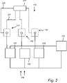
- Fig. 2 is a schematic view of a battery system 130 comprising a plurality of battery packs 131, 132, 133 arranged in parallel for powering a load 110, and a battery management system 115.
- the load 110 may be powered by the first, second and third battery packs 131, 132, 133 by means of contactors (not shown), i.e. by connecting the first, second and third battery packs 131, 132, 133 to the load 110.
- the first, second and third battery packs 131, 132, 133 may be disconnected from the load 110 by means of the contactors.
- the embodiment shown in Fig. 2 may for example be implemented in the vehicle 1 of Fig. 1 .
- the load 110 in Fig. 2 may be an electric machine.
- the battery system 130 comprises a first battery pack 131, a second battery pack 132 and a third battery pack 133, but it should be noted that any number of battery packs may be included in the battery system 130.
- the battery management system 115 comprises a first sensor unit 141 configured to measure at least one quantity of the first battery pack 131, such as e.g. temperature, current and/or voltage, and comprises a second sensor unit 142 configured to measure at least one quantity of the second battery pack 132, such as e.g. temperature, current and/or voltage, and comprising a third sensor unit 143 configured to measure at least one quantity of the third battery pack 133, such as e.g. temperature, current and/or voltage.
- an associated sensor unit here being the first, second and third sensor units 141, 142, 143 exist for each battery pack, here being the corresponding first, second and third battery packs 131, 132, 133.
- the first, second and third sensor units 141, 142, 143 are configured to provide condition data, here in the form of measured data (i.e. of the at least one quantity).
- the control unit 117 being e.g. an electronic control unit, of the EST management system 115 is configured to receive the condition data from the first, second and third sensor units 141, 142, 143.
- the EST management system 115 is configured to transfer the condition data from each one of the first, second and third sensor units 141, 142, 143 by means of a first data transfer mode and a second transfer mode.
- the EST management system 115 is configured to transfer the condition data from the first sensor unit 141 to the control unit 117 via a first data transfer means 120, being e.g.
- condition data may be transferred from the first sensor unit 141 to the control unit 117 by means of a first transfer mode, i.e. the first data transfer means 120, and by means of a second data transfer mode, i.e. the second data transfer means 121.
- the EST management system 115 comprises a first communication bus 120 for transferring the condition data from the first sensor unit 141 by means of the first data transfer mode, and a second communication bus 121 for transferring the condition data from the first sensor unit 141 by means of the second data transfer mode, the second communication bus 121 being different to the first communication bus 120.
- the EST management system 115 is further configured to transfer the condition data from the second sensor unit 142 to the control unit 117, and is configured to transfer the condition data from the third sensor unit 143 to the control unit 117 via a respectively first and second data transfer modes, e.g. as described with reference to Fig 3A-3C .
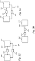
- Figs. 3A-3C shows a first unit 240 in data communication with a second unit 217.
- the first unit 240 is configured to provide condition data, e.g. in the form of measured data or data regarding a calculation or estimation of a first internal state of the EST system.
- the first unit 240 comprises a sensor unit as e.g. either one of the first, second and third sensor units 141, 142, 143 of the embodiment in Fig. 2 .
- the second unit 217 is configured to receive the condition data from the first unit 240, the second unit 217 being a control unit as e.g. the control unit 117 of the embodiment in Fig. 2 .
- the data transfer between the first unit 240 and the second unit 217 is realised by a first communication bus 220 and a second communication bus 221, different to the first communication bus 220.
- the condition data here referred to as being comprised in message 222, or data message 222
- the same condition data, or the same message 222 is transferred from the first unit 240 to the second unit 217 by the first and second communication buses 220, 221.
- the data transfer between the first unit 240 and the second unit 217 is realised by a single communication bus 220, being e.g. the first communication bus 220.
- the condition data is transferred from the first unit 240 to the second unit 217 as a first message 223 and a second message 224 different to the first message 223.
- the condition data is transferred from the first unit 240 to the second unit 217 by means of a first transfer mode, i.e. by the first message 223, and by means of a second data transfer mode, i.e. by the second message 224.
- the first and second messages 223, 224 may comprise condition data of the same type but transferred at different times (i.e.
- the data representing the condition data in the second message 224 may e.g. be of a different type than the data representing the condition data in the first message 223.
- the first message 223 may comprise the condition data in the unit or power
- the second message 224 may comprise the condition data in the units of current and voltage.
- the embodiments of Fig. 3A and Fig. 3B are combined.
- the data transfer between the first unit 240 and the second unit 217 is realised by a first communication bus 220 and a second communication bus 221, different to the first communication bus 220 as well as that the condition data is transferred from the first unit 240 to the second unit 217 as a first message 223 and a second message 224 different to the first message 223.
- the condition data may be transferred from the first unit 240 to the second unit 217 by means of a first transfer mode, i.e. by the first communication bus 220 and the first message 223, and by means of a second data transfer mode, i.e. by the second communication bus 221 and the second message 224.
- the first and second messages 223, 224 may comprise condition data of the same type but transferred at different times (i.e. being separate messages with regards to the time of transfer), or may comprise condition data of different types.
- the EST system comprises a first unit configured to provide condition data and a second unit configured to receive the condition data from the first unit by means of a first data transfer mode, as for example described with reference to Figs. 3A-3C .
- the condition data is transferred from the first unit by means of a second data transfer mode.
- the first step S10 comprises transferring the condition data from the first unit by means of the first data transfer mode.
- the first and second data transfer modes are different.
- the first data transfer mode comprises transferring the condition data via a first communication bus
- the second data transfer mode comprises transferring the condition data via a second communication bus being different to the first communication bus.
- the first data transfer mode may comprise transferring the condition data via a first message
- the second data transfer mode may comprise transferring the condition data via a second message being different to the first message.
- the second message may be of a different type than the first message, or the data representing the condition data in the second message may be of a different type than the data representing the condition data in the first message.
- the first data transfer mode may comprise transferring the condition data via the first message and the first communication bus
- the second data transfer mode may comprise transferring the condition data via the second message and the second communication bus.
- a fault or error regarding the condition data in relation to the first data transfer mode is received.
- the second step S20 may comprise the step of identifying or detecting a fault or error regarding the condition data in relation to the first data transfer mode.
- the first unit may comprise a first sensor configured to provide measurement data as the condition data.
- the second step S20 may be based on a fault or error regarding the measurement data in relation to the first data transfer mode.
- the first unit comprises a calculation unit configured to provide a calculation or estimation of a first internal state of the EST system as the condition data.
- the second step S20 may be based on a fault or error regarding the first internal state in relation to the first data transfer mode.
- the fault or error may origin from the condition data, e.g. the measurement data or the calculation of the first internal state, or may origin from the transfer of the condition data.
- the fault or error is at least one of the following: transmission error of the condition data, repetition of the condition data, deletion of the condition data, corruption of the condition data, delay of the condition data and masquerade error of the condition data.
- a third step S30 it is determined whether or not a first criteria of the vehicle is achieved, the first criteria comprising at least that the condition data transferred by the first unit by means of the second data transfer mode is received by the second unit.
- the first criteria may further comprise that the fault or error is expressive of an at least temporarily lack of operability of the EST system.
- a vehicle condition which, in case of an at least temporarily lack of operability of the EST system, results in a potentially harmful situation is identified, wherein the first criteria comprises such potentially harmful situation.
- the vehicle condition, in case of an at least temporarily lack of operability of the EST system may be defined as a potentially harmful situation if the expected result of the at least temporarily lack of operability of the EST system is more hazardous than that of the fault or error regarding the condition data in relation to the first data transfer mode.
- a fifth step S50 and in response of achieving the first criteria in the third step S30, the EST system is operated despite the fault or error and using the condition data transferred by means of the second data transfer mode.
- the EST system comprises an EST management system having an electronic control unit being configured to perform the method as described with reference to Fig. 4 .
- the EST management system may e.g. be a battery management system.
- the method as described with reference to Fig. 4 may be implemented in a computer program.
- the computer program may comprise program code means for performing the method as described with reference to Fig. 4 , when the program is run on a computer.
- the method as described with reference to Fig. 4 may be implemented in a computer readable medium carrying a computer program comprising program code means for performing the method as described with reference to Fig. 4 , when the computer program is run on a computer.
- control unit 17, 117 may be configured to perform the method as described with reference to Fig. 4 . That is, the control unit is, at least, configured to
Landscapes
- Engineering & Computer Science (AREA)
- Mechanical Engineering (AREA)
- Transportation (AREA)
- Life Sciences & Earth Sciences (AREA)
- Sustainable Energy (AREA)
- Power Engineering (AREA)
- Sustainable Development (AREA)
- Automation & Control Theory (AREA)
- Human Computer Interaction (AREA)
- Physics & Mathematics (AREA)
- General Physics & Mathematics (AREA)
- Electric Propulsion And Braking For Vehicles (AREA)
Abstract
The present invention relates to a method for improving the availability of an energy storage or transformation, EST, system of a vehicle, the EST system comprising a first unit configured to provide condition data and a second unit configured to receive the condition data from the first unit by means of a first data transfer mode. The method comprises:
- transferring the condition data from the first unit by means of a second data transfer mode,
- receiving a fault or error regarding the condition data in relation to the first data transfer mode,
- determining whether or not a first criteria of the vehicle is achieved, the first criteria comprising at least that the condition data transferred by the first unit by means of the second data transfer mode is received by the second unit,
- in response of achieving the first criteria, operating the EST system despite the fault or error and using the condition data transferred by means of the second data transfer mode.
Description
- The present invention relates to a method for improving the availability of an energy storage or transformation system of a vehicle, an energy storage or transformation management system, an energy or transformation system, and to a vehicle.
- A vehicle typically comprises an engine or machine for propelling the vehicle. The engine may be powered by various means, such as e.g. by a liquid or gaseous fuel in an internal combustion engine, or by electric power to an electric machine. Moreover, hybrid solutions exist in which e.g. the vehicle is propelled both by an internal combustion engine and an electric machine. In either way, an energy storage device is used to store the energy needed in order to propel the vehicle. For an electric machine, the energy storage devices may be batteries or supercapacitors, or, in case the vehicle is equipped with a fuel-cell system, the fuel cells being energy transformation devices, the energy storage devices are hydrogen containing storages. The energy storage device and the energy transformation devices may commonly be referred to as energy storage or transformation devices, and the system to which they belong may be referred to as an energy storage or transformation system.
- Vehicles are thus in need of the energy storage or transformation system for providing propulsion power for traction. In certain situations, the propulsion power is particularly needed, e.g. when a vehicle is subject to a potentially hazardous situation, like passing a railway crossing, for which a sufficient propulsion power is required to get out of the hazardous situation. Thus, the readiness of propulsion power and the availability of the energy storage or transformation system are important to keep as a high a possible. For internal combustion engine vehicles, a high availability of propulsion power is based on concepts where in case of e.g. a restart of an ECU, the ECU synchronizes itself to the still ongoing combustion process. Compared to internal combustion engine vehicles, electric vehicles are facing other challenges and uncertainties regarding e.g. electric range, drivability, power availability, and remaining-useful-life of vehicles mainly due to complex electrochemical, thermal, and ageing dynamics of the energy storage or transformation devices. Also safety hazards like short-circuit, explosion in case of vehicle crash, thermal runway, etc are important to supervise. Therefore, the energy storage or transformation system of an electric vehicle requires advanced monitoring, control, and fault diagnostics to manage all these robustness and safety issues. In spite of such advanced monitoring, a fault or error may lead to problematic problems of the energy storage or transformation system, such as e.g. an at least temporarily lack of operability of the energy storage or transformation system. Thus, there is a drive in the industry for an improved availability of the energy storage and transformation system.
- It is an object of the present invention to at least partly alleviate the shortcomings discussed above in relation to known energy storage or transformation systems, and to improve the availability of the energy storage or transformation systems.
- According to at least a first aspect of the present invention, a method for improving the availability of an energy storage or transformation, EST, system of a vehicle is provided. The EST system comprises a first unit configured to provide condition data and a second unit configured to receive the condition data from the first unit by means of a first data transfer mode. The method comprises:
- transferring the condition data from the first unit by means of a second data transfer mode,
- receiving a fault or error regarding the condition data in relation to the first data transfer mode,
- determining whether or not a first criteria of the vehicle is achieved, the first criteria comprising at least that the condition data transferred by the first unit by means of the second data transfer mode is received by the second unit,
- in response of achieving the first criteria, operating the EST system despite the fault or error and using the condition data transferred by means of the second data transfer mode.
- Hereby, the EST system may be operated based on the condition data from the second data transfer mode even though a fault or error is present in the condition data of the first data transfer mode. Thus, the availability of the EST system is improved. Moreover, potential undesired, or even hazardous, vehicle conditions which otherwise could be the result of the fault or error, can be avoided, as the fault or error of the condition data in relation to the first data transfer mode is circumvented with the transfer of the condition data by means of the second data transfer mode. Stated differently, the EST system is kept in an operable condition despite the fault or error regarding the condition parameter in relation to the first data transfer mode.
- As will be described in further detail later, but which is briefly mentioned here, the condition data may be condition data of a component (i.e. a component condition parameter), measured data from e.g. a sensor (which measure quantities like e.g. current, voltage, temperature, pressure, gassing, stress etc inside EST system), actuation signal data for an actuator, or data of an estimated or calculated internal state of the EST system, such as e.g. state of charge or state of power of a battery, a battery cell or a block of battery cells. Stated differently, the fault or error of regarding the condition data in relation to the first data transfer mode may comprise both fault diagnostic of components (e.g. fault in a sensor) and diagnostics of measurement and calculations errors (e.g. erroneous calculations of an internal state of the EST system). Correspondingly, the fault or error may origin from condition data of a component, measured data from e.g. a sensor, actuation signal data from an actuator (e.g. a contactor or a relay) or a calculated internal state of the EST system. Moreover, the fault or error may be related to the first data transfer mode, and not a fault or error in the condition data per se, as will be described later.
- According to at least one example embodiment, the energy storage or transformation system is an energy storage system, such as e.g. a battery system comprising a plurality of EST devices in the form of battery packs or batteries. According to at least one example embodiment, the energy storage or transformation system is an energy transformation system, such as e.g. a fuel cell system comprising a plurality of EST devices in the form of fuel cells.
- The first criteria may be one or several of the criteria described in further detail later. Thus, the fist criteria may comprise a combination of several criteria of which all need to be achieved in order to operate the EST system despite the fault or error regarding the condition data in relation to the first data transfer mode. The first criteria may be referred to as a safety criteria.
- According to at least one example embodiment, the step of receiving a fault or error regarding the condition data in relation to the first data transfer mode may comprise identifying a fault or error regarding the condition data in relation to the first data transfer mode.
- According to at least one example embodiment, the method comprises:
- transferring the condition data from the first unit by means of the first data transfer mode.
- Thus, at least prior to receiving the fault or error, the condition data may be transferred from the first unit by means of the first and second data transfer modes.
- According to at least one example embodiment, the first data transfer mode comprises transferring the condition data via a first communication bus, and the second data transfer mode comprises transferring the condition data via a second communication bus being different to the first communication bus.
- Hereby, the condition data may be transferred via two different communication buses, and thus, redundancy of condition data is provided in a simple yet effective manner. The first communication bus may e.g. extend from the first unit to the second unit, or extend along at least a sub-part from the first unit to the second unit. Correspondingly, the second communication bus may e.g. extend from the first unit to the second unit, or extend along at least a different sub-part from the first unit to the second unit. According to at least one example embodiment, the first communication bus is parallel to the second communication bus.
- According to at least one example embodiment, the first data transfer mode comprises transferring the condition data via a first message, and the second data transfer mode comprises transferring the condition data via a second message being different to the first message.
- Hereby, redundancy of condition data is provided by means of different messages. For example, the condition data may be transferred via the first message at a first instance in time, and then then condition data may be transferred via the second message at a second instance in time, different to the first instance. Thus, the second message may simply be a message of the same type as the first message but transferred at different point in time.
- According to at least one example embodiment, the second message is of a different type than the first message, or the data representing the condition data in the second message is of a different type than the data representing the condition data in the first message.
- Thus, the second message may be, or comprise, a message of another type as the first message, e.g. by using another protocol, or other type of data. For example, the first message may comprise the condition data as data in the unit power, while the second message may comprise the condition data as corresponding data but in the units current and voltage. As the product of the current and voltage is equal to the power for corresponding data, the first and the second messages comprise different data representing the condition data.
- According to at least one example embodiment, the first data transfer mode comprises transferring the condition data via the first message and the first communication bus, and the second data transfer mode comprises transferring the condition data via the second message and the second communication bus.
- Hereby, the redundancy of the condition data can be further improved. For example, the second message transferred via the second communication bus may be of a different type than the first message, or the data representing the condition data in the second message may be of a different type than the data representing the condition data in the first message, as earlier described.
- According to at least one example embodiment, the first criteria comprises that the fault or error is expressive of an at least temporarily lack of operability of the EST system.
- Thus, the step of operating the EST system despite the fault or error regarding the condition data in relation to the first data transfer mode by using the condition data transferred by means of the second data transfer mode, may be performed in response to that the fault or error is expressive of an at least temporarily lack of operability of the EST system. That is, the fault or error would lead to an at least temporarily lack of operability of the EST system, such as e.g. an at least temporarily power loss, if not the condition data transferred by means of the second data transfer mode would be used. Hereby, an at least temporarily lack of operability of the EST system, potentially leading to an hazardous vehicle condition, which otherwise could be the result of the fault or error can be avoided, as the condition data transferred by means of the second data transfer mode is used instead of the condition data transferred by means of the first data transfer mode.
- According to at least one example embodiment, in which the EST system is a battery system, the first criteria comprises a fault or error expressive of an at least temporarily lack of power of the battery system. That is, the fault or error regarding the condition data in relation to the first data transfer mode is a fault or error which would otherwise cause a lack of power of the battery system (e.g. a fault which would cause the battery system to at least temporarily shut down), if not the condition data by means of the second transfer mode would be available. Thus, for embodiments in which the EST system is a battery system, the temporarily lack of operability may be a temporarily lack of power.
- According to at least one example embodiment, the first criteria comprises determining that the EST system can be operated in a safe and robust manner despite the fault or error regarding the condition data in relation to the first data transfer mode. Thus, despite the fault or error regarding the condition data in relation to the first data transfer mode, the first criteria may provide a safeguard that the EST system may be operated based on the condition data transferred by means of the second data transfer mode in a safe and robust manner.
- According to at least one example embodiment, the method comprises:
- identifying a vehicle condition which, in case of an at least temporarily lack of operability of the EST system, results in a potentially harmful situation, and wherein the first criteria comprises such potentially harmful situation.
- That is, the fault or error regarding the condition data in relation to the first data transfer mode would lead to a potentially harmful situation, e.g. a hazardous or dangerous vehicle condition, if not the condition data transferred by means of the second data transfer mode would be used. Hereby potentially harmful situations can be avoided. Thus, based on identifying a vehicle condition leading to such potentially harmful situation, the method comprises operating the EST system despite the fault or error regarding the condition data in relation to the first data transfer mode. For example, in case the vehicle is positioned at a railway crossing in risk of being hit by the train, the vehicle condition is identified as, in case of an at least temporarily lack of operability of the EST system (e.g. as the previously exemplified lack of power for the battery system), a potentially harmful situation. Thus, if the first criteria is achieved, i.e. that the vehicle condition is identified as a potentially harmful situation in case of an at least temporarily lack of operability of the EST system, the EST system may be operated despite the fault or error regarding the condition data in relation to the first data transfer mode by using the condition data transferred by means of the second data transfer mode. Hereby, the vehicle can at least pass the railway crossing in a safe manner. After passing the railway crossing, the vehicle condition may no longer be identified as a potentially harmful situation, and the first criteria may no longer be achieved.
- According to at least one example embodiment, the first criteria is based on vehicle functional safety or safety-critical functionality, such as e.g. ISO 26262. That is, the first criteria may comprise vehicle functional safety or safety-critical functionality, and the EST system may be operated despite the fault or error regarding the condition data in relation to the first data transfer mode in order to ensure vehicle functional safety or safety-critical functionality.
- According to at least one example embodiment, the method comprises, in response of not achieving the first criteria, enabling or allowing the EST system to at least temporarily lack operability, e.g. to be at least temporarily shut down, in response to the fault or error regarding the condition data in relation to the first data transfer mode. That is, if not the first criteria is achieved, and the fault or error is expressive of an at least temporarily lack of operability of the EST system, the EST system may act in response to such fault or error and enable the EST system to at least temporarily shut down.
- According to at least one example embodiment, the vehicle condition, in case of at least temporarily lack of operability of the EST system, is defined as a potentially harmful situation if the expected result of the at least temporarily lack of operability of the EST system is more hazardous than that of the fault or error regarding the condition data in relation to the first data transfer mode.
- That is, the fault or error regarding the condition data in relation to the first data transfer mode may be rationalized with regards to the first criteria. Stated differently, the fault or error may be rationalized with regards to the potentially harmful situation being a result of the fault or error regarding the condition data in relation to the first data transfer mode. In other words, the first criteria may consider such potentially harmful situation to infer about severity of the fault or error.
- According to at least one example embodiment, the vehicle condition comprises a vehicle state or a vehicle driving situation. Thus, the potentially harmful situation may be a dangerous state of the vehicle, e.g. thermal runway, or the potentially harmful situation may be a dangerous driving situation, e.g. a railroad crossing.
- According to at least one example embodiment, the fault or error regarding the condition data in relation to the first data transfer mode is one of the following: transmission error of the condition data, repetition of the condition data, deletion of the condition data, corruption of the condition data, delay of the condition data and masquerade error of the condition data.
- Thus, alternatively, or in addition to, that the fault or error is related to the condition data per se, the fault or error may be related to the data transfer mode of the condition data. Corruption of the condition data may e.g. also include insertion of data, i.e. additional message which is interpreted to have correct payload, or re-sequencing of data, i.e. gateway messages in the wrong order.
- According to at least one example embodiment, the condition data is subject to a communication protection measure to achieve data integrity.
- Hereby, undesired use or access to the condition data may be prevented.
- According to at least one example embodiment, the first unit comprises a first sensor configured to provide measurement data as the condition data, and wherein receiving a fault or error is based on a fault or error regarding the measurement data in relation to the first data transfer mode
- Hereby, the EST system may be operated using the measurement data transferred by means of the second data transfer mode even though a fault or error regarding the measurement data in relation to the first data transfer mode is present. Thus, the availability of the EST system may be improved. That is, in case of a sensor failure resulting in a fault or error in the measured parameter, or the data transfer thereof by means of the first data transfer mode, measurement transferred by means of the second data transfer mode may be used instead.
- According to at least one example embodiment, the first unit comprises an calculation unit configured to provide a calculation of a first internal state of the EST system as the condition data, and wherein receiving a fault or error is based on a fault or error regarding the first internal state in relation to the first data transfer mode.
- Hereby, the EST system may be operated using the calculation or estimation of the first internal state transferred by means of the second data transfer mode even though a fault or error regarding the first internal state in relation to the first data transfer mode is present. Thus, the availability of the EST system may be improved. That is, in case of a sensor failure, or failure of the calculation unit, resulting in a fault or error in the calculation or estimation of the first internal state, or the data transfer thereof by means of the first data transfer mode, the calculation or estimation of the first internal state transferred by means of the second data transfer mode may be used instead.
- According to at least one example embodiment, the first criteria comprises determining that an indicative parameter for the first internal state indicates that there is no fault or error in the calculation or estimation of the first internal state. Hereby, it is more likely that the fault or error originates from the calculation, or calculation unit performing the calculation, than an actual underlying fault or error of the first internal state. Thus, in case the condition data in the form of the calculation of the first internal state is transferred by means of the first data transfer mode, and a fault or error is received in regarding the first internal state in relation to the first data transfer mode, the indicative parameter(s), being condition data in the form of the calculation of the first internal state but of another type (i.e. the underlying parameters used for determining the first internal state) may be transferred by means of the second data transfer mode. For example, if a state-of-power estimations for a battery or battery cell is indicated as very low then the indicated parameters, such as the current and voltage can be used to verify if such low state of power is actually the case, or if it is more likely that the fault or error originates from the calculation or estimation, or calculation unit performing the calculation.
- According to at least one example embodiment, the sensing unit comprises one or more sensors connected to the calculation unit, for performing the calculation of the first internal state.
- According to at least one example embodiment, the condition data is a calculation of a first internal state in the EST system and the fault or error is determined by comparing the calculation of the first internal state with a threshold value.
- Hereby, a simple yet effective means for determining a fault or error in the calculation of the internal state per se is provided. Hereby, the faults or errors may be classified in terms of their significance. If the fault or error is within a certain limit, e.g. below the threshold value, it is classified as normal function behaviour, and no further concern is given to the fault or error (i.e. the fault or error is considered in void). On the other hand, if the fault or error is outside of said limit, e.g. above the threshold value, it is classified as an actual fault or error, and dealt with as previously described.
- According to at least one example embodiment, the fault or error may be subject to a residual analysis. That is, analyzing the statistical or stochastic properties of estimation error and subsequently comparing it with the expected probability distribution of such faults or error under given operating conditions. If the error or fault lies outside the boundaries of an expected probability distribution, it can be treated as an outlier. To ensure availability of safety-critical functionality and robustness under potentially harmful situations, the method may detect such large errors (i.e. outliers) and isolate them using stochastic thresholds.
- According to a second aspect of the present invention, an EST management system comprising an electronic control unit being configured to perform the method according to the first aspect of the invention is provided. The EST management system may e.g. be a battery management system.
- According to a third aspect of the present invention, a computer program is provided. The computer program comprises program code means for performing the method of the first aspect of the invention, when the program is run on a computer.
- Such computer program may e.g. be implemented in an electronic control unit, ECU, of the vehicle.
- According to a fourth aspect of the present invention, a computer readable medium carrying a computer program comprising program code means for performing the method of the first aspect of the invention, when the computer program is run on a computer, is provided.
- According to a fifth aspect of the present invention, an EST system of a vehicle comprising the EST management system according to the second aspect of the present invention is provided. Alternatively, the EST system of the vehicle may comprise the computer program according to the third aspect, or the computer readable medium according to the fourth aspect.
- According to at least one example embodiment, the EST system comprises the first unit configured to provide condition data, wherein the electronic control unit of the EST management system is configured to receive the condition data from the first unit by means of a first data transfer mode, wherein the EST system comprises a first communication bus for transferring the condition data by means of the first data transfer mode, and a second communication bus for transferring the condition data by means of the second data transfer mode, the second communication bus being different to the first communication bus.
- According to a sixth aspect of the present invention, a vehicle comprising an EST system according to the fifth aspect of the present invention is provided. The vehicle is e.g. an electric vehicle powered by electricity from energy storage or transformation devices, such as batteries or fuel cells.
- Effects and features of the second to sixth aspects of the invention are largely analogous to those described above in connection with the first aspect of the invention. Embodiments mentioned in relation to the first aspect of the invention are largely compatible with the second to sixth aspects of the invention.
- Further advantages and features of the present disclosure are disclosed and discussed in the following description and the accompanying drawings.
- With reference to the appended drawings, below follows a more detailed description of embodiments of the invention cited as examples. In the drawings:
-
Fig. 1 is a side schematic view of a vehicle in accordance with an example embodiment of the invention; -
Fig. 2 is a schematic view of an energy storage or transformation system in the form of a battery system in accordance with an example embodiment of the invention; -
Figs. 3A-3C are schematic views describing the transfer of condition data from the first unit to the second unit by means of first and second data transfer modes; and -
Fig. 4 is a flowchart illustrating the steps of a method in accordance with example embodiments of the invention. - With reference to
Fig. 1 , avehicle 1, here embodied as aheavy duty truck 1, is disclosed for which a method, an energy storage or transformation (EST)system 30, and/or anEST management system 15 of a kind disclosed in the present invention is advantageous. However, the method, theEST system 30 orEST management system 15 may as well be implemented in other types of vehicles or vessels, such as in busses, light-weight trucks, passenger cars, marine applications etc. Thevehicle 1 is an electric vehicle, such as a full electric vehicle or a hybrid, comprising at least oneelectric machine 10 powered by theEST system 30, wherein in the example ofFig. 1 , theEST system 30 comprises threeEST devices EST system 30 is abattery system 30 and that the energy storage ortransformation devices battery packs EST management system 15 is thus abattery management system 15 configured to manage thebattery system 30 and e.g. connected and disconnect the battery packs 31, 32, 33 relative theelectric machine 10. Moreover, thebattery management system 15 comprises acontrol unit 17 arranged and configured for controlling the operation of thebattery system 30. Thevehicle 1 typically further comprises other parts of the powertrain such as transmission, drive shafts and wheels (not shown in detail). -
Fig. 2 is a schematic view of abattery system 130 comprising a plurality of battery packs 131, 132, 133 arranged in parallel for powering aload 110, and abattery management system 115. Theload 110 may be powered by the first, second and third battery packs 131, 132, 133 by means of contactors (not shown), i.e. by connecting the first, second and third battery packs 131, 132, 133 to theload 110. Correspondingly, the first, second and third battery packs 131, 132, 133 may be disconnected from theload 110 by means of the contactors. The embodiment shown inFig. 2 may for example be implemented in thevehicle 1 ofFig. 1 . Thus, theload 110 inFig. 2 may be an electric machine. - The
battery system 130 comprises afirst battery pack 131, asecond battery pack 132 and athird battery pack 133, but it should be noted that any number of battery packs may be included in thebattery system 130. Thebattery management system 115 comprises afirst sensor unit 141 configured to measure at least one quantity of thefirst battery pack 131, such as e.g. temperature, current and/or voltage, and comprises asecond sensor unit 142 configured to measure at least one quantity of thesecond battery pack 132, such as e.g. temperature, current and/or voltage, and comprising athird sensor unit 143 configured to measure at least one quantity of thethird battery pack 133, such as e.g. temperature, current and/or voltage. Thus, an associated sensor unit, here being the first, second andthird sensor units third sensor units - The
control unit 117, being e.g. an electronic control unit, of theEST management system 115 is configured to receive the condition data from the first, second andthird sensor units Figs. 3A-3C , theEST management system 115 is configured to transfer the condition data from each one of the first, second andthird sensor units Fig. 2 , theEST management system 115 is configured to transfer the condition data from thefirst sensor unit 141 to thecontrol unit 117 via a first data transfer means 120, being e.g. afirst communication bus 120, extending from thefirst sensor unit 141 to thecontrol unit 117, and a second data transfer means 121, being e.g. asecond communication bus 121, extending from thefirst sensor unit 141 to thecontrol unit 117 in parallel to the first data transfer means 120. Thus, the condition data may be transferred from thefirst sensor unit 141 to thecontrol unit 117 by means of a first transfer mode, i.e. the first data transfer means 120, and by means of a second data transfer mode, i.e. the second data transfer means 121. In other words, theEST management system 115 comprises afirst communication bus 120 for transferring the condition data from thefirst sensor unit 141 by means of the first data transfer mode, and asecond communication bus 121 for transferring the condition data from thefirst sensor unit 141 by means of the second data transfer mode, thesecond communication bus 121 being different to thefirst communication bus 120. TheEST management system 115 is further configured to transfer the condition data from thesecond sensor unit 142 to thecontrol unit 117, and is configured to transfer the condition data from thethird sensor unit 143 to thecontrol unit 117 via a respectively first and second data transfer modes, e.g. as described with reference toFig 3A-3C . -
Figs. 3A-3C shows afirst unit 240 in data communication with asecond unit 217. Thefirst unit 240 is configured to provide condition data, e.g. in the form of measured data or data regarding a calculation or estimation of a first internal state of the EST system. For example, thefirst unit 240 comprises a sensor unit as e.g. either one of the first, second andthird sensor units Fig. 2 . Thesecond unit 217 is configured to receive the condition data from thefirst unit 240, thesecond unit 217 being a control unit as e.g. thecontrol unit 117 of the embodiment inFig. 2 . - As shown in
Fig. 3A , the data transfer between thefirst unit 240 and thesecond unit 217 is realised by afirst communication bus 220 and asecond communication bus 221, different to the first communication bus 220.Thus, the condition data, here referred to as being comprised inmessage 222, ordata message 222, may be transferred from thefirst unit 240 to thesecond unit 217 by means of a first transfer mode, i.e. by thefirst communication bus 220, and by means of a second data transfer mode, i.e. by thesecond communication bus 221. As shown inFig. 3A , the same condition data, or thesame message 222, is transferred from thefirst unit 240 to thesecond unit 217 by the first andsecond communication buses - As shown in
Fig. 3B , the data transfer between thefirst unit 240 and thesecond unit 217 is realised by asingle communication bus 220, being e.g. thefirst communication bus 220. However, inFig. 3B , the condition data is transferred from thefirst unit 240 to thesecond unit 217 as afirst message 223 and asecond message 224 different to thefirst message 223. Thus, the condition data is transferred from thefirst unit 240 to thesecond unit 217 by means of a first transfer mode, i.e. by thefirst message 223, and by means of a second data transfer mode, i.e. by thesecond message 224. The first andsecond messages second message 224 may e.g. be of a different type than the data representing the condition data in thefirst message 223. For example, thefirst message 223 may comprise the condition data in the unit or power, and thesecond message 224 may comprise the condition data in the units of current and voltage. - As shown in
Fig. 3C , the embodiments ofFig. 3A and Fig. 3B are combined. Thus, the data transfer between thefirst unit 240 and thesecond unit 217 is realised by afirst communication bus 220 and asecond communication bus 221, different to thefirst communication bus 220 as well as that the condition data is transferred from thefirst unit 240 to thesecond unit 217 as afirst message 223 and asecond message 224 different to the first message 223.Thus, the condition data may be transferred from thefirst unit 240 to thesecond unit 217 by means of a first transfer mode, i.e. by thefirst communication bus 220 and thefirst message 223, and by means of a second data transfer mode, i.e. by thesecond communication bus 221 and thesecond message 224. As for the embodiment ofFig. 3B , the first andsecond messages - A method for improving the availability of an EST system of a vehicle, such as e.g. the EST system in the form of a
battery system Figs. 1-2 will now be described. The EST system comprises a first unit configured to provide condition data and a second unit configured to receive the condition data from the first unit by means of a first data transfer mode, as for example described with reference toFigs. 3A-3C . - In a first step S10, the condition data is transferred from the first unit by means of a second data transfer mode. According to at least one example embodiment, (depending on the fault or error described below), the first step S10 comprises transferring the condition data from the first unit by means of the first data transfer mode. As described with reference to
Figs. 3A-3C , the first and second data transfer modes are different. For example, the first data transfer mode comprises transferring the condition data via a first communication bus, and the second data transfer mode comprises transferring the condition data via a second communication bus being different to the first communication bus. Moreover, the first data transfer mode may comprise transferring the condition data via a first message, and the second data transfer mode may comprise transferring the condition data via a second message being different to the first message. The second message may be of a different type than the first message, or the data representing the condition data in the second message may be of a different type than the data representing the condition data in the first message. As described with reference toFig. 3C , the first data transfer mode may comprise transferring the condition data via the first message and the first communication bus, and the second data transfer mode may comprise transferring the condition data via the second message and the second communication bus. - In a second step S20, a fault or error regarding the condition data in relation to the first data transfer mode is received. The second step S20 may comprise the step of identifying or detecting a fault or error regarding the condition data in relation to the first data transfer mode.
- The first unit may comprise a first sensor configured to provide measurement data as the condition data. Thus, the second step S20 may be based on a fault or error regarding the measurement data in relation to the first data transfer mode. Additionality or alternatively, the first unit comprises a calculation unit configured to provide a calculation or estimation of a first internal state of the EST system as the condition data. Thus, the second step S20 may be based on a fault or error regarding the first internal state in relation to the first data transfer mode. The fault or error may origin from the condition data, e.g. the measurement data or the calculation of the first internal state, or may origin from the transfer of the condition data. According to at least one example embodiment, the fault or error is at least one of the following: transmission error of the condition data, repetition of the condition data, deletion of the condition data, corruption of the condition data, delay of the condition data and masquerade error of the condition data.
- In a third step S30, it is determined whether or not a first criteria of the vehicle is achieved, the first criteria comprising at least that the condition data transferred by the first unit by means of the second data transfer mode is received by the second unit. The first criteria may further comprise that the fault or error is expressive of an at least temporarily lack of operability of the EST system.
- In a fourth step S40, a vehicle condition which, in case of an at least temporarily lack of operability of the EST system, results in a potentially harmful situation is identified, wherein the first criteria comprises such potentially harmful situation. The vehicle condition, in case of an at least temporarily lack of operability of the EST system, may be defined as a potentially harmful situation if the expected result of the at least temporarily lack of operability of the EST system is more hazardous than that of the fault or error regarding the condition data in relation to the first data transfer mode.
- In a fifth step S50, and in response of achieving the first criteria in the third step S30, the EST system is operated despite the fault or error and using the condition data transferred by means of the second data transfer mode.
- According to at least one example embodiment, the EST system comprises an EST management system having an electronic control unit being configured to perform the method as described with reference to
Fig. 4 . The EST management system may e.g. be a battery management system. The method as described with reference toFig. 4 may be implemented in a computer program. Thus, the computer program may comprise program code means for performing the method as described with reference toFig. 4 , when the program is run on a computer. Alternatively the method as described with reference toFig. 4 may be implemented in a computer readable medium carrying a computer program comprising program code means for performing the method as described with reference toFig. 4 , when the computer program is run on a computer. - Turning back to
Figs. 1 and2 , thecontrol unit Fig. 4 . That is, the control unit is, at least, configured to - receive a fault or error regarding the condition data in relation to the first data transfer mode,
- determine whether or not a first criteria of the vehicle is achieved, the first criteria comprising at least that the condition data transferred by the first unit by means of the second data transfer mode is received by the second unit,
- in response of achieving the first criteria, operate the EST system despite the fault or error and using the condition data transferred by means of the second data transfer mode.
- It should be noted that the naming of the steps not necessarily, but might according to at least one example embodiment, relate to the order in which the steps are carried out. Thus, the order of the steps may be different than that explained here, and the
control unit Figs. 1-2 may be configured to carry out one or several of the steps. Moreover, one or more of the steps may be combined and carried out simultaneously. - It is to be understood that the present invention is not limited to the embodiments described above and illustrated in the drawings; rather, the skilled person will recognize that many changes and modifications may be made within the scope of the appended claims.
- Additionally, variations to the disclosed embodiments can be understood and effected by the skilled person in practicing the claimed inventive concept, from a study of the drawings, the disclosure, and the appended claims. In the claims, the word "comprising" does not exclude other elements or steps, and the indefinite article "a" or "an" does not exclude a plurality. The mere fact that certain measures are recited in mutually different dependent claims does not indicate that a combination of these measures cannot be used to advantage.
Claims (15)
- A method for improving the availability of an energy storage or transformation, EST, system of a vehicle, the EST system comprising a first unit configured to provide condition data and a second unit configured to receive the condition data from the first unit by means of a first data transfer mode, the method comprising:- transferring the condition data from the first unit by means of a second data transfer mode,- receiving a fault or error regarding the condition data in relation to the first data transfer mode,- determining whether or not a first criteria of the vehicle is achieved, the first criteria comprising at least that the condition data transferred by the first unit by means of the second data transfer mode is received by the second unit,- in response of achieving the first criteria, operating the EST system despite the fault or error and using the condition data transferred by means of the second data transfer mode.
- The method according to claim 1, wherein the first data transfer mode comprises transferring the condition data via a first communication bus, and the second data transfer mode comprises transferring the condition data via a second communication bus being different to the first communication bus.
- The method according to any one of the preceding claims, wherein the first data transfer mode comprises transferring the condition data via a first message, and the second data transfer mode comprises transferring the condition data via a second message being different to the first message.
- The method according to claim 3, wherein the second message is of a different type than the first message, or wherein the data representing the condition data in the second message is of a different type than the data representing the condition data in the first message.
- The method according to claims 2-4, wherein the first data transfer mode comprises transferring the condition data via the first message and the first communication bus, and the second data transfer mode comprises transferring the condition data via the second message and the second communication bus.
- The method according to any one of the preceding claims, wherein the first criteria comprises that the fault or error is expressive of an at least temporarily lack of operability of the EST system.
- The method according to any one of the preceding claims, comprising:- identifying a vehicle condition which, in case of an at least temporarily lack of operability of the EST system, results in a potentially harmful situation, and wherein the first criteria comprises such potentially harmful situation.
- The method according to claim 7, wherein the vehicle condition, in case of an at least temporarily lack of operability of the EST system, is defined as a potentially harmful situation if the expected result of the at least temporarily lack of operability of the EST system is more hazardous than that of the fault or error regarding the condition data in relation to the first data transfer mode.
- The method according to any one of the preceding claims, wherein the fault or error regarding the condition data in relation to the first data transfer mode is at least one of the following: transmission error of the condition data, repetition of the condition data, deletion of the condition data, corruption of the condition data, delay of the condition data and masquerade error of the condition data.
- The method according to any one of the preceding claims, wherein the first unit comprises a first sensor configured to provide measurement data as the condition data, and wherein receiving a fault or error is based on a fault or error regarding the measurement data in relation to the first data transfer mode.
- The method according to any one of the preceding claims, wherein the first unit comprises a calculation unit configured to provide a calculation of a first internal state of the EST system as the condition data, and wherein receiving a fault or error is based on a fault or error regarding the first internal state in relation to the first data transfer mode.
- An EST management system comprising an electronic control unit being configured to perform the method according to any one of claims 1-11.
- An EST system of a vehicle comprising an EST management system according to claim 12.
- The EST system according to claim 13, comprising the first unit configured to provide condition data, wherein the electronic control unit of the EST management system is configured to receive the condition data from the first unit by means of a first data transfer mode, wherein the EST system comprises a first communication bus for transferring the condition data by means of the first data transfer mode, and a second communication bus for transferring the condition data by means of the second data transfer mode, the second communication bus being different to the first communication bus.
- A vehicle comprising an EST system according to claim 14.
Priority Applications (4)
| Application Number | Priority Date | Filing Date | Title |
|---|---|---|---|
| EP21170156.0A EP4079560A1 (en) | 2021-04-23 | 2021-04-23 | A method for improving the availability of an energy storage or transformation system |
| US17/659,739 US20220340150A1 (en) | 2021-04-23 | 2022-04-19 | Method for improving the availability of an energy storage or transformation system |
| CN202210415622.5A CN115320381A (en) | 2021-04-23 | 2022-04-20 | Method for increasing the availability of an energy storage or conversion system |
| EP22169442.5A EP4079561A1 (en) | 2021-04-23 | 2022-04-22 | A method for improving the availability of an energy storage or transformation system |
Applications Claiming Priority (1)
| Application Number | Priority Date | Filing Date | Title |
|---|---|---|---|
| EP21170156.0A EP4079560A1 (en) | 2021-04-23 | 2021-04-23 | A method for improving the availability of an energy storage or transformation system |
Publications (1)
| Publication Number | Publication Date |
|---|---|
| EP4079560A1 true EP4079560A1 (en) | 2022-10-26 |
Family
ID=75659909
Family Applications (2)
| Application Number | Title | Priority Date | Filing Date |
|---|---|---|---|
| EP21170156.0A Withdrawn EP4079560A1 (en) | 2021-04-23 | 2021-04-23 | A method for improving the availability of an energy storage or transformation system |
| EP22169442.5A Pending EP4079561A1 (en) | 2021-04-23 | 2022-04-22 | A method for improving the availability of an energy storage or transformation system |
Family Applications After (1)
| Application Number | Title | Priority Date | Filing Date |
|---|---|---|---|
| EP22169442.5A Pending EP4079561A1 (en) | 2021-04-23 | 2022-04-22 | A method for improving the availability of an energy storage or transformation system |
Country Status (3)
| Country | Link |
|---|---|
| US (1) | US20220340150A1 (en) |
| EP (2) | EP4079560A1 (en) |
| CN (1) | CN115320381A (en) |
Citations (2)
| Publication number | Priority date | Publication date | Assignee | Title |
|---|---|---|---|---|
| JP2012050156A (en) * | 2010-08-24 | 2012-03-08 | Nichicon Corp | On-vehicle charging unit and charging system having the on-vehicle charging unit |
| JP6344302B2 (en) * | 2015-05-08 | 2018-06-20 | 株式会社デンソー | Battery controller |
Family Cites Families (18)
| Publication number | Priority date | Publication date | Assignee | Title |
|---|---|---|---|---|
| US10486720B2 (en) * | 2008-08-04 | 2019-11-26 | Ge Global Sourcing Llc | Vehicle communication systems and control systems |
| WO2011080915A1 (en) * | 2009-12-28 | 2011-07-07 | パナソニック株式会社 | Electronic apparatus, method for controlling electronic apparatus, computer program, and recording medium |
| DE102010045514B4 (en) * | 2010-09-15 | 2018-03-29 | Audi Ag | A method for monitoring an electrical energy storage that provides an electrical voltage for an electric machine of a motor vehicle |
| US9196930B2 (en) * | 2011-03-24 | 2015-11-24 | Ford Global Technologies, Llc | Vehicle battery cell with integral control circuit |
| DE102011076757A1 (en) * | 2011-05-31 | 2012-12-06 | Robert Bosch Gmbh | Security architecture, battery and a motor vehicle with a corresponding battery |
| JP5904050B2 (en) * | 2012-08-03 | 2016-04-13 | ソニー株式会社 | Power storage device |
| KR101484208B1 (en) * | 2012-12-14 | 2015-01-21 | 현대자동차 주식회사 | The motor velocity compensating device of the fuel cell vehicle and sensor, the motor velocity compensating method thereof |
| KR101394751B1 (en) * | 2012-12-28 | 2014-05-15 | 현대자동차주식회사 | Method for detecting fuse disconnection of dc-dc converter |
| EP2808846A1 (en) * | 2013-05-31 | 2014-12-03 | Cabeco AB | Device and method for detecting faults in electronic systems |
| EP3149499B1 (en) * | 2014-06-02 | 2018-01-31 | Volvo Truck Corporation | A method and system for monitoring the status of battery cells |
| US10446887B2 (en) * | 2014-07-21 | 2019-10-15 | Ford Global Technologies, Llc | Battery thermal management system including thermal interface material with integrated heater element |
| US10516683B2 (en) * | 2017-02-15 | 2019-12-24 | Ford Global Technologies, Llc | Systems and methods for security breach detection in vehicle communication systems |
| CN106997970B (en) * | 2017-03-08 | 2019-11-05 | 深圳市科陆电子科技股份有限公司 | A kind of battery pack data communication system |
| US10994617B2 (en) * | 2018-11-19 | 2021-05-04 | Ford Global Technologies, Llc | Distributed battery thermal runaway detection |
| KR102791433B1 (en) * | 2018-12-06 | 2025-04-03 | 현대자동차주식회사 | Charging control method for battery of vehicle |
| KR102481113B1 (en) * | 2019-02-11 | 2022-12-26 | 주식회사 엘지에너지솔루션 | System and method for checking slave battery management system |
| CN212257606U (en) * | 2020-05-15 | 2020-12-29 | 南京国电南自电网自动化有限公司 | Energy storage battery management system for wired and wireless hybrid networking communication |
| KR20220069137A (en) * | 2020-11-19 | 2022-05-27 | 한국전자통신연구원 | Device and method for predicting state of battery |
-
2021
- 2021-04-23 EP EP21170156.0A patent/EP4079560A1/en not_active Withdrawn
-
2022
- 2022-04-19 US US17/659,739 patent/US20220340150A1/en active Pending
- 2022-04-20 CN CN202210415622.5A patent/CN115320381A/en active Pending
- 2022-04-22 EP EP22169442.5A patent/EP4079561A1/en active Pending
Patent Citations (2)
| Publication number | Priority date | Publication date | Assignee | Title |
|---|---|---|---|---|
| JP2012050156A (en) * | 2010-08-24 | 2012-03-08 | Nichicon Corp | On-vehicle charging unit and charging system having the on-vehicle charging unit |
| JP6344302B2 (en) * | 2015-05-08 | 2018-06-20 | 株式会社デンソー | Battery controller |
Also Published As
| Publication number | Publication date |
|---|---|
| US20220340150A1 (en) | 2022-10-27 |
| EP4079561A1 (en) | 2022-10-26 |
| CN115320381A (en) | 2022-11-11 |
Similar Documents
| Publication | Publication Date | Title |
|---|---|---|
| US12162503B2 (en) | Method for improving the availability of an energy storage or transformation system of a vehicle | |
| CN107776408B (en) | Vehicle system, battery system, and control method of battery system | |
| US10322641B2 (en) | Vehicle power supply device | |
| CN204956144U (en) | High voltage power distribution system of fuel cell big bus car | |
| CN105572540B (en) | Adaptive electric automobile high-voltage safety fault diagnosis early warning positioning monitoring system | |
| EP3149499B1 (en) | A method and system for monitoring the status of battery cells | |
| CN107472029B (en) | High-voltage fault detection method for vehicle and vehicle | |
| KR101326508B1 (en) | Trouble diagnosis method of current sensor for high voltage battery system | |
| Taylor et al. | System safety and ISO 26262 compliance for automotive lithium-ion batteries | |
| Kong et al. | Comprehensive fault diagnosis and fault-tolerant protection of in-vehicle intelligent electric power supply network | |
| EP3521096B1 (en) | Battery management apparatus | |
| CN107923942A (en) | Method for monitoring the status of multiple battery cells in a battery pack | |
| CN112512855B (en) | System for driving an energy accumulator and method for charging | |
| EP4079560A1 (en) | A method for improving the availability of an energy storage or transformation system | |
| JP2021190353A (en) | Battery secondary use determination system and battery secondary use determination method | |
| JP2005210892A (en) | ENERGY-SUPPLYING DEVICE OF HYBRID VEHICLE WITH AT LEAST ONE x-BY-WIRE SYSTEM | |
| CN110780218A (en) | Method for plausibility checking of measured variables of sensors in motor vehicles | |
| Taylor et al. | High-voltage battery system concepts for ISO 26262 compliance | |
| CN114527397A (en) | Method for monitoring an energy source in a vehicle network | |
| US12024051B2 (en) | Battery control system | |
| US20250196648A1 (en) | Method for controlling prevention of disconnecting a battery pack in an energy storage system of a vehicle | |
| JP2025142702A (en) | Anomaly Detection System | |
| WO2024155218A1 (en) | Method, controller and system for handling isolation faults in battery operated system | |
| Taylor et al. | SAE International | |
| CN117897629A (en) | Method for verifying current measurement in an energy system |
Legal Events
| Date | Code | Title | Description |
|---|---|---|---|
| PUAI | Public reference made under article 153(3) epc to a published international application that has entered the european phase |
Free format text: ORIGINAL CODE: 0009012 |
|
| STAA | Information on the status of an ep patent application or granted ep patent |
Free format text: STATUS: THE APPLICATION HAS BEEN PUBLISHED |
|
| AK | Designated contracting states |
Kind code of ref document: A1 Designated state(s): AL AT BE BG CH CY CZ DE DK EE ES FI FR GB GR HR HU IE IS IT LI LT LU LV MC MK MT NL NO PL PT RO RS SE SI SK SM TR |
|
| STAA | Information on the status of an ep patent application or granted ep patent |
Free format text: STATUS: THE APPLICATION IS DEEMED TO BE WITHDRAWN |
|
| 18D | Application deemed to be withdrawn |
Effective date: 20230427 |