EP4079465A1 - Offline programming device and offline programming method - Google Patents
Offline programming device and offline programming method Download PDFInfo
- Publication number
- EP4079465A1 EP4079465A1 EP20901449.7A EP20901449A EP4079465A1 EP 4079465 A1 EP4079465 A1 EP 4079465A1 EP 20901449 A EP20901449 A EP 20901449A EP 4079465 A1 EP4079465 A1 EP 4079465A1
- Authority
- EP
- European Patent Office
- Prior art keywords
- point
- display area
- teaching
- error
- display
- Prior art date
- Legal status (The legal status is an assumption and is not a legal conclusion. Google has not performed a legal analysis and makes no representation as to the accuracy of the status listed.)
- Pending
Links
Images







Classifications
-
- G—PHYSICS
- G05—CONTROLLING; REGULATING
- G05B—CONTROL OR REGULATING SYSTEMS IN GENERAL; FUNCTIONAL ELEMENTS OF SUCH SYSTEMS; MONITORING OR TESTING ARRANGEMENTS FOR SUCH SYSTEMS OR ELEMENTS
- G05B19/00—Program-control systems
- G05B19/02—Program-control systems electric
- G05B19/18—Numerical control [NC], i.e. automatically operating machines, in particular machine tools, e.g. in a manufacturing environment, so as to execute positioning, movement or co-ordinated operations by means of program data in numerical form
- G05B19/406—Numerical control [NC], i.e. automatically operating machines, in particular machine tools, e.g. in a manufacturing environment, so as to execute positioning, movement or co-ordinated operations by means of program data in numerical form characterised by monitoring or safety
- G05B19/4069—Simulating machining process on screen
-
- B—PERFORMING OPERATIONS; TRANSPORTING
- B25—HAND TOOLS; PORTABLE POWER-DRIVEN TOOLS; MANIPULATORS
- B25J—MANIPULATORS; CHAMBERS PROVIDED WITH MANIPULATION DEVICES
- B25J9/00—Program-controlled manipulators
- B25J9/16—Program controls
- B25J9/1656—Program controls characterised by programming, planning systems for manipulators
- B25J9/1671—Program controls characterised by programming, planning systems for manipulators characterised by simulation, either to verify existing program or to create and verify new program, CAD/CAM oriented, graphic oriented programming systems
-
- B—PERFORMING OPERATIONS; TRANSPORTING
- B25—HAND TOOLS; PORTABLE POWER-DRIVEN TOOLS; MANIPULATORS
- B25J—MANIPULATORS; CHAMBERS PROVIDED WITH MANIPULATION DEVICES
- B25J9/00—Program-controlled manipulators
- B25J9/16—Program controls
- B25J9/1656—Program controls characterised by programming, planning systems for manipulators
- B25J9/1664—Program controls characterised by programming, planning systems for manipulators characterised by motion, path, trajectory planning
-
- G—PHYSICS
- G05—CONTROLLING; REGULATING
- G05B—CONTROL OR REGULATING SYSTEMS IN GENERAL; FUNCTIONAL ELEMENTS OF SUCH SYSTEMS; MONITORING OR TESTING ARRANGEMENTS FOR SUCH SYSTEMS OR ELEMENTS
- G05B19/00—Program-control systems
- G05B19/02—Program-control systems electric
- G05B19/18—Numerical control [NC], i.e. automatically operating machines, in particular machine tools, e.g. in a manufacturing environment, so as to execute positioning, movement or co-ordinated operations by means of program data in numerical form
- G05B19/406—Numerical control [NC], i.e. automatically operating machines, in particular machine tools, e.g. in a manufacturing environment, so as to execute positioning, movement or co-ordinated operations by means of program data in numerical form characterised by monitoring or safety
- G05B19/4068—Verifying part program on screen, by drawing or other means
-
- G—PHYSICS
- G05—CONTROLLING; REGULATING
- G05B—CONTROL OR REGULATING SYSTEMS IN GENERAL; FUNCTIONAL ELEMENTS OF SUCH SYSTEMS; MONITORING OR TESTING ARRANGEMENTS FOR SUCH SYSTEMS OR ELEMENTS
- G05B2219/00—Program-control systems
- G05B2219/30—Nc systems
- G05B2219/35—Nc in input of data, input till input file format
- G05B2219/35345—Display entry of high level program together with corresponding nc program
-
- G—PHYSICS
- G05—CONTROLLING; REGULATING
- G05B—CONTROL OR REGULATING SYSTEMS IN GENERAL; FUNCTIONAL ELEMENTS OF SUCH SYSTEMS; MONITORING OR TESTING ARRANGEMENTS FOR SUCH SYSTEMS OR ELEMENTS
- G05B2219/00—Program-control systems
- G05B2219/30—Nc systems
- G05B2219/35—Nc in input of data, input till input file format
- G05B2219/35349—Display part, programmed locus and tool path, traject, dynamic locus
-
- G—PHYSICS
- G05—CONTROLLING; REGULATING
- G05B—CONTROL OR REGULATING SYSTEMS IN GENERAL; FUNCTIONAL ELEMENTS OF SUCH SYSTEMS; MONITORING OR TESTING ARRANGEMENTS FOR SUCH SYSTEMS OR ELEMENTS
- G05B2219/00—Program-control systems
- G05B2219/30—Nc systems
- G05B2219/39—Robotics, robotics to robotics hand
- G05B2219/39044—Estimate error model from error at different attitudes and points
-
- G—PHYSICS
- G05—CONTROLLING; REGULATING
- G05B—CONTROL OR REGULATING SYSTEMS IN GENERAL; FUNCTIONAL ELEMENTS OF SUCH SYSTEMS; MONITORING OR TESTING ARRANGEMENTS FOR SUCH SYSTEMS OR ELEMENTS
- G05B2219/00—Program-control systems
- G05B2219/30—Nc systems
- G05B2219/39—Robotics, robotics to robotics hand
- G05B2219/39298—Trajectory learning
-
- G—PHYSICS
- G05—CONTROLLING; REGULATING
- G05B—CONTROL OR REGULATING SYSTEMS IN GENERAL; FUNCTIONAL ELEMENTS OF SUCH SYSTEMS; MONITORING OR TESTING ARRANGEMENTS FOR SUCH SYSTEMS OR ELEMENTS
- G05B2219/00—Program-control systems
- G05B2219/30—Nc systems
- G05B2219/40—Robotics, robotics mapping to robotics vision
- G05B2219/40314—Simulation of program locally before remote operation
Definitions
- This disclosure relates to an offline programming device and an offline programming method.
- PTL 1 discloses a method for creating a robot operation program by arranging icons each of which represents a command to a robot in order of movement using a GUI (graphical user interface).
- GUI graphical user interface
- OLP offline programming
- the present invention is made in view of the circumstances described above, and an object of the present invention is to provide an offline programming device and an offline programming method in which a user can understand an error that occurs between teaching points.
- the offline programming device includes: an input circuitry that receives input of a plurality of teaching points; a creation circuitry that determines one or more intermediate points located between adjacent teaching points and creates an operation program for a robot, the operation program including the plurality of teaching points and the intermediate point; the simulator that simulates a movement trajectory of the robot when the operation program is executed; and the display that displays a GUI screen representing the movement trajectory.
- the GUI screen includes a first display area showing a time series sequence of the plurality of teaching points and a second display area showing a time series sequence of a plurality of the intermediate points between some of the plurality of teaching points included in the first display area on a larger scale than the first display area.
- the first display area can display a section between the teaching points, the section including a point in time when the error occurs, by a first error display method, and the second display area can display the intermediate point corresponding to the point in time when the error occurs, by a second error display method.
- An offline programming method includes: a step of receiving input of a plurality of teaching points; a step of determining one or more intermediate points located between adjacent teaching points and creating an operation program for a robot, the operation program including the plurality of teaching points and the intermediate point; and a step of simulating a movement trajectory of the robot when the operation program is executed; and a step of displaying a GUI screen representing the movement trajectory.
- the GUI screen includes a first display area showing a time series sequence of the plurality of teaching points and a second display area showing a time series sequence of a plurality of the intermediate points between some of the plurality of teaching points included in the first display area on a larger scale than the first display area.
- the first display area can display a section between the teaching points, the section including a point in time when the error occurs, by a first error display method, and the second display area can display the intermediate point corresponding to the point in time when the error occurs, by a second error display method.
- the intermediate point corresponding to the point in time when the error occurs is displayed by the second error display method.
- the error occurs between the teaching points can be notified to the user.
- the present invention can be realized not only as an offline programming device and an offline programming method provided with the characteristic configuration described above, but also as a computer program for causing a computer to execute the characteristic steps in the offline programming method.
- Part or all of the offline programming device can be realized as a semiconductor integrated circuit, or as an offline programming system including the offline programming device.
- an error occurs between teaching points can be notified to the user.
- An offline programming device of this embodiment is a device for creating a program that defines a movement of a robot without being connected to the actual robot.
- the robot is a vertically articulated robot in one example, a horizontally articulated robot in another example, and a parallel link robot in yet another example.
- FIG. 1 is a block diagram of an example configuration of the offline programming device.
- the OLP device 100 is configured, for example, by a computer.
- the OLP device 100 has a processor 110, a non-transient memory 120, a transient memory 130, an input/output interface 140, an input device 150, and a display device 160.
- the transient memory 130 is a volatile memory, for example, an SRAM (Static Random Access Memory), a DRAM (Dynamic Random Access Memory), or the like.
- the non-transient memory 120 is a non-volatile memory, for example, a flash memory, a hard disk, a ROM (Read Only Memory), or the like.
- the non-transient memory 120 stores an OLP program 170 as a computer program and data used for execute the OLP program 170.
- the OLP device 100 includes a computer.
- the OLP program 170 as the computer program stored in the memory device of the computer is executed by the processor 110 as a CPU so that each function of the OLP device 100 is performed.
- the OLP program 170 can be stored in a recording medium, for example, a flash memory, a ROM, a CD-ROM or the like.
- the processor 110 executes the OLP program 170 and displays a programming screen as described later.
- the processor 110 is not limited to a CPU.
- the processor 110 can be a hardware logic circuit, for example, an ASIC (Application Specific Integrated Circuit (ASIC), a gate array, a field programmable gate array (FPGA) or the like.
- ASIC Application Specific Integrated Circuit
- FPGA field programmable gate array
- the hardware logic circuit is configured to perform the same processing as the OLP program 170.
- the input/output interface 140 is connected by the input device 150 and the display device 160.
- the input device 150 is, for example, a keyboard, a mouse, a touchpad, a pen tablet or the like, and is used by the user to input data into the OLP device 100.
- the display device 160 is a liquid crystal panel or an organic EL (Electro Luminescence) panel, and can display text information, images, and the like in response to a command.
- the input/output interface 140 is compliant with, for example, USB (Universal Serial Bus), or HDMI (High-Definition Multimedia Interface; "HDMI" is a registered trademark).
- the input/output interface 140 can receive data from the input device 150 and output data for display to the display device 160.
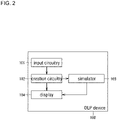
- FIG. 2 is a functional block diagram showing an example of the functions of the OLP device 100 according to this embodiment.
- the OLP device 100 has functions as an input circuitry 101, a creation circuitry 102, a simulator 103, and a display 104.
- the input circuitry 101 receives a command that defines a movement of the robot at a certain point in time, input from the user.
- the command includes a teaching point that defines the posture of the robot, i.e., the movement point, a movement direction of the robot, such as a straight line, a circular arc, etc., and a type of work to be performed by the robot, such as deburring, welding, moving, etc.
- the user can input time series commands at multiple points in time to the input circuitry 101.
- the creation circuitry 102 determines one or more intermediate points connecting adjacent teaching points, and creates an operation program for the robot that includes the plurality of the teaching points and the intermediate points.
- the operation program is executed on the robot which is an actual machine, the robot moves according to the movement trajectory in accordance with the time series commands.
- the simulator 103 simulates the movement trajectory of the robot when the operation program is executed. In other words, the simulator 103 computes the movement trajectory of the robot in a three-dimensional virtual space.
- the simulator 103 can detect an error about the movement trajectory.
- error includes an event that the computed movement trajectory cannot be realized.
- the error can include interference between robot components or between a robot component and another object, or an abnormal movement that exceeds the allowable range, for example, a movement in which the movement speed exceeds the maximum output of the motor or a movement that deviates from the movable range.
- the simulator 103 can identify the point in time when the error occurs.
- the simulator 103 can detect an event that requires warning to the user (warning event) about the movement trajectory.
- warning event refers to an event that the computed movement trajectory can be realized but meets a specific warning condition.
- the warning condition may include, for example, a movement in which the movement speed is equal to or below the maximum output of the motor but above a specified value, an approach that exceeds the allowable range with respect to another object, or the like.
- the simulator 103 can identify the point in time when the warning event occurs.
- the display 104 displays a programming screen for creating an operation program.
- the programming screen is also a GUI screen that the movement trajectory is represented.
- the programming screen will be described later.
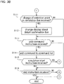
- FIGS. 3A and 3B are flowcharts showing an example of the operation procedure of the offline programming device according to this embodiment.
- the processor 110 executes each of the following processes.
- the programming screen is displayed on the display device 160 (step S101). Since no commands have been registered at this time, the programming screen in its initial state, which does not include icons, images (video), and the like, is displayed.
- the user can input a command to the OLP device 100 by the input device 150.
- the processor 110 receives the command input from the user (step S102).
- the processor 110 adds a command block, which is a symbol (icon) indicating the command which is input, to the command list area, which is one area included in the programming screen (step S103).
- FIG. 4 shows an example of the programming screen.
- the programming screen 200 includes a command list area 300, a simulation bar 400, and an animation display area 600.
- a command list area 300 a plurality of command boxes 310 are arranged in a row in time series order.
- the command boxes 310 are arranged in the order in which the commands are executed.
- the processor 110 determines whether the instruction to start the simulation is received or not (step S104).
- step S102 the processor 110 executes step S102. This allows additional input of the command. If the instruction to start the simulation is received (YES in step S104), the processor 110 creates an operation program for the robot based on the input commands (step S105). Furthermore, the processor 110 executes the simulation (step S106). That is, the processor 110 simulates the movement trajectory when the operation program specified by the input command is executed.
- the processor 110 displays a simulation bar on the display device 160 (step S107) and displays an animation of the movement trajectory generated by the simulation (step S108).
- the simulation bar 400 is provided on the side of the command list area 300.
- the simulation bar 400 is located parallel to the row of the command boxes 310 in the command list area 300.
- the simulation bar 400 is a linear section parallel to the row of the command boxes 310.
- the simulation bar 400 corresponds to the command boxes 310 in the command list area 300.
- a portion beside (the right of) each of the command boxes 310 in the simulation bar 400 corresponds to each command box 310.
- a portion of the simulation bar 400, which is beside the command box 310 containing the text "straight line approach 1" corresponds to this command box 310.
- the simulation bar 400 has a length equals to or greater than the length of the row in which the command boxes 310 displayed in the command list area 300 arranged. This means that the simulation bar 400 corresponds to all the command boxes 310 displayed in the command list area 300.
- the simulation bar 400 is displayed in a color (for example, white) that is different from an error color and from a warning color. If an error is detected, the portion of the simulation bar 400 corresponding to the point in time when the error occurs is displayed in the error color (for example, red). Hereinafter, the portion of the simulation bar 400 that is displayed in the error color is referred to as a first error region 420.
- the first error region 420 indicates the teaching point near the point in time of occurrence of the error.
- the first error region 420 is located in a range from the command box 310 containing the text "straight line deburr 1" to the command box 310 containing the text "straight line deburr 2". Therefore, it is understood that the error occurs in the range from the teaching point of the command box 310 containing the text "straight line deburr 1" to the teaching point of the command box 310 containing the text "straight line deburr 2".
- the portion of the simulation bar 400 corresponding to the point in time when the warning event occurs is displayed in the warning color (for example, yellow).
- the portion of the simulation bar 400 that is displayed in the warning color is referred to as the first warning region 430.
- the first warning region 430 indicates the teaching point near the point in time of occurrence of the warning event.
- the first warning region 430 is located in a range from the command box 310 containing the text "straight line deburr 3" to the command box 310 containing the text "straight line depart 1". Therefore, it is understood that the warning event occurs in the range from the teaching point of the command box 310 containing the text "straight line deburr 3" to the teaching point of the command box 310 containing the text "straight line depart 1".
- the animation display area 600 displays the movement trajectory of the robot when the operation program is executed on the display device 160, with animation (graphical display is performed).
- the animation allows the user to visually confirm the movement trajectory of the robot.
- the user can select any one point on the simulation bar 400.
- the user can select a point on the simulation bar 400 by moving the mouse pointer to the point and clicking, or by touching the position corresponding to the above-described point with a finger or a pen on a touchpad or a pen tablet.
- the processor 110 determines whether a selection of a point on the simulation bar 400 from the user is received (step S109). If a selection of the point is not received from the user (NO in step S109), the processing by the OLP device 100 ends. If a selection of the point is received on the simulation bar 400 from the user is received (YES in step S109), the processor 110 displays a detail confirmation bar on the display device 160 (step S110).
- FIG. 5 shows an example of the programming screen including the detail confirmation bar.
- a point on the simulation bar 400 is selected, a pointer 411 is displayed at the position of the selected point, and a detail confirmation bar 500 is displayed on the side of the simulation bar 400.
- the detail confirmation bar (second display area) 500 is displayed in part of the animation display area 600.
- the detail confirmation bar 500 shows a time series sequence of a plurality of intermediate points between adjacent teaching points.
- the time series sequence of the intermediate points in the section before and after the selected point in the simulation bar 400 is shown on a larger scale than the simulation bar 400.
- the detail confirmation bar 500 can display detailed information that cannot be displayed on the simulation bar 400.
- the detail confirmation bar 500 includes tick marks indicating each of one or more teaching points and a plurality of intermediate points.
- the tick mark for the intermediate point is represented by a thin line and the tick mark for the teaching point is represented by a thick line.
- the intermediate point and the teaching point are displayed distinguishable from each other.
- the detail confirmation bar 500 is displayed in a color (for example, black) that is different from the error color and from the warning color. If an error is detected, the portion of the detail confirmation bar 500 corresponding to the point in time when the error occurs is displayed in the error color.
- the portion of the detail confirmation bar 500 that is displayed in the error color is referred to as a second error region 520.
- the second error region 520 indicates the intermediate point near the point in time of occurrence of the error.
- the second error region 520 is located in a range from the intermediate point of the tick mark "027" to the intermediate point of the tick mark "029". Therefore, it is understood that the error occurs in the range. This allows the user to roughly identify the point in time when the error occurs by the simulation bar 400, and to identify the point in time when the error occurs in detail by the detail confirmation bar 500.
- the portion of the detail confirmation bar 500 corresponding to the point in time when the warning event occurs is displayed in the warning color.
- the portion of the detail confirmation bar 500 that is displayed in the warning color is referred to as a second warning region. Since the detail confirmation bar 500 shows a time series sequence of the intermediate points, the second warning region indicates the intermediate point near the point in time of occurrence of the warning event. In the example in FIG. 5 , although the second warning region is outside the display section of the detail confirmation bar 500 and is not shown, but is displayed in the same form as the second error region 520. This allows the user to roughly identify the point in time when the warning event occurs by the simulation bar 400, and to identify the point in time when the warning event occurs in detail by the detail confirmation bar 500.
- the user can slide the pointer 411 along the simulation bar 400.
- the user can slide the pointer 411 by dragging or swiping with the pointer 411 selected.
- the point selected on the simulation bar 400 is changed.
- the processor 110 determines whether a change of the selection point on the simulation bar 400 from the user is received (step S111). If the change of the selection point from the user is not received (NO in step Sill), the processor 110 changes the process to be executed to step S113. If the change of the selection point from the user is received (YES in step Sill), the processor 110 makes the display device 160 change the display of the detail confirmation bar 500 (step S112).
- FIGS. 6A and 6B show one example of the change in the display of the detail confirmation bar 500.
- FIGS. 6A and 6B show before and after the change in the display of the detail confirmation bar 500.
- an indicator 511 is displayed at the vertical center of the detail confirmation bar 500, for indicating the selection point.
- the point in time indicated by the indicator 511 is the same as the point in time selected by the pointer 411. That is, the point in time selected by the pointer 411 and indicated on the simulation bar 400 is the same as the point in time indicated by the indicator 511 on the detail confirmation bar 500.
- the indicator 511 is displayed fixedly. That is, the indicator 511 is always located at the vertical center of the detail confirmation bar 500, and the position of the indicator 511 does not change even if the pointer 411 is slid.
- the section indicated by the detail confirmation bar 500 is changed according to the change in position of the pointer 411.
- the detail confirmation bar 500 indicates the section from the tick mark "021” to the tick mark "039”
- the detail confirmation bar 500 indicates the section from the tick mark "013" to the tick mark "032”.
- the section displayed by the detail confirmation bar 500 changes according to the change of the selection point by the user. Therefore, the user can slide the pointer 411 to display the detailed information of the section he/she wants to check on the detail confirmation bar 500.
- FIGS. 6A the detail confirmation bar 500 indicates the section from the tick mark "021” to the tick mark "039”
- the detail confirmation bar 500 indicates the section from the tick mark "013" to the tick mark "032”.
- the indicator 511 is a dashed line extending horizontally, but it is not limited to this.
- the indicator 511 may be a solid line extending horizontally, or it may be a circle, an arrow, or other symbol.
- the position of the second error region 520 is changed as a result of the above-described change.
- the second error region 520 appears in the section where the error occurs in the detail confirmation bar 500. Therefore, when the position of the pointer 411 is changed and the display section of the detail confirmation bar 500 is changed, the position of the second error region 520 changes by the same amount as the change in the display section and in the same direction as the change in the display section. If part or all of the second error region 520 changes to deviate from the display range of the detail confirmation bar 500, the part or all of the second error region 520 is not displayed in the detail confirmation bar 500. Likewise, the position of the second warning region also changes as the display section of the detail confirmation bar 500 changes.
- the user may edit the operation program and change a part of the movement trajectory of the robot. For example, if an error occurs where a part of the robot interferes with another object, the user changes the movement trajectory to avoid the interference.
- the user can use the detail confirmation bar 500 to edit the operation program.
- the user adds a new command to edit the operation program.
- the user can adjust the pointer 411 to the point in time at which he/she wishes to add a command, and instruct the OLP device 100 to add a new command at that point in time.
- the user confirm that one intermediate point is selected on the detail confirmation bar 500, and then give an instruction to add a command to that intermediate point to the OLP device 100.
- the instruction to add a command can be realized by various methods.
- a button for adding a command may be displayed in the command list area 300, and the user may select the button to instruct to add a command.
- a drop-down list containing multiple items may be displayed in response to a click or touch operation on the programming screen 200, and the user may select the "add command" item in the drop-down list to instruct to add a command.
- the processor 110 determines whether the instruction to add a command from the user is received or not (step S113). If the instruction to add a command is not received (NO in step S113), the processor 110 advances the process to be executed to step S116. On the other hand, if the instruction to add a command is received (YES in step S113), the processor 110 adds the command to the point in time that is currently selected (step S114). In adding a command, a teaching point is set at the selected point in time. Moreover, the movement direction of the robot and the type of work included in the new command are specified by the user.
- the processor 110 determines whether the instruction to start the simulation is received or not (step S115). If the instruction to start the simulation is not received (YES in step S115), the processor 110 changes the process to be executed to step S105. As a result, an operation program containing the added command is created and the simulation is executed.
- step S115 determines whether an instruction to end the processes is received from the user or not (step S116). If the instruction to end is not received (NO in step S116), the processor 110 changes the process to be executed to step S111. If the instruction to quit of the processes from the user is received (YES in step S116), the processor 110 ends the process of the OLP program 170. This concludes the processing by the OLP device 100.
- the programming screen 200 in particular the simulation bar 400 and the detail confirmation bar 500 have various display embodiments. Examples of the display embodiments of the programming screen 200 will be described below.
- the simulation bar 400 changes its display form depending on the point in time when the error or the warning event occurs. More specifically, the display form the simulation bar 400 varies depending on whether the error or the warning event occurs between two adjacent teaching points or at a teaching point.
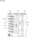
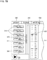
- FIGS. 7A and 7B illustrate the display forms of the simulation bar depending on the point in time when the error occurs.
- FIG. 7A shows an example of the display form of the simulation bar 400 when the error occurs between two adjacent teaching points.
- FIG. 7B shows an example of the display form of the simulation bar 400 when the error occurs at a teaching point.
- the first error region 420 is located in the section between two adjacent teaching points that sandwich the point in time when the error occurs, as shown in FIG. 7A .
- section between two teaching points may include the teaching points at both ends or may exclude the teaching points at both ends.
- “Section between two teaching points” may be a section including the teaching point at one end and not including the teaching point at the other end. In the example in FIG.
- the first error region 420 is located in a section between the teaching point at the command box 310 for "straight line deburr 1" and the teaching point at the command box 310 for "straight line deburr 2".
- the user can understand that the error occurs between the teaching point of "straight line deburr 1" and the teaching point of "straight line deburr 2".
- the detail confirmation bar 500 indicates an error occurrence point in a more detailed manner.
- the second error region 520 is located in a smaller section than the first error region 420 in the simulation bar 400.
- the second error region 520 is provided in a section between a plurality of intermediate points including the point in time at which the error occurs. For example, when an error occurs during a period of time including multiple intermediate points, the second error region 520 is located in that period of time of the detail confirmation bar 500.
- the second error region 520 is located in a section including the intermediate point, for example, in a section between intermediate points (or teaching points) of both sides each of which is adjacent to the intermediate point.
- the first error region 420 is located in a section over three consecutive teaching points, as shown in FIG. 7B .
- the three consecutive teaching points are the teaching point at the time the error occurred and the two teaching points of both sides that are adjacent to it.
- the first error region 420 is located in a section over the teaching point of the command box 310 for "straight line approach 3"
- the teaching point of the command box 310 for "straight line deburr 1” and the teaching point of the command box 310 for "straight line deburr 2". This allows the user to understand that the error occurs at the teaching point of "straight line deburr 1".
- the detail confirmation bar 500 also indicates an error occurrence point in a more detailed manner. For example, if an error occurs at only one teaching point, the second error region 520 is located in a section including the teaching point, for example, a section between the intermediate points of both sides each of which is adjacent to this teaching point. In another example, if an error occurs in a period of time that includes one teaching point and one or more intermediate points, the second error region 520 is located in that period of time in the detail confirmation bar 500.
- FIG. 8A shows an example of the display form of the simulation bar when an error and a warning event occur
- FIG. 8B shows another example.
- FIG. 8A shows an example in which the first error region 420 and the first warning region 430 are far from each other.
- the first error region 420 and the first warning region appear in the section defined by the point in time of occurrence of the error and the warning event.
- the teaching point at one end of the first error region 420 is the same as the teaching point at the other end of the first warning region
- each of the first error region 420 and the first warning region 430 is displayed entirely.
- the error occurs in the section between the teaching point of the command box 310 for "straight line approach 3" and the teaching point of the command box 310 for "straight line deburr 1"
- the warning event occurs in the section between the teaching point of the command box 310 for "straight line deburr 2" and the teaching point of the command box 310 for "straight line deburr 3".
- the first error region 420 is located in a section between the teaching point of the command box 310 for "straight line approach 3" and the teaching point of the command box 310 for "straight line deburr 1"
- the first warning region 430 is located in a section between the teaching points of the command box 310 for "straight line deburr 2" and the teaching points of the command box 310 for "straight line deburr 3".
- the first error region 420 and the first warning region 430 are far from each other.
- FIG. 8B shows an example in which the first error region 420 and the first warning region 430 partially overlap each other in the simulation bar 400.
- the first error region 420 and the first warning region 430 overlap each other at least in part the first error region 420 is displayed being given priority.
- the range the first error region 420 and the first warning region overlap is displayed as the first error region 420 and not as the first warning region 430.
- the error occurs in the section between the teaching point of the command box 310 for "straight line approach 3" and the teaching point of the command box 310 for "straight line deburr 1", and the warning event occurs at the teaching point of the command box 310 for "straight line deburr 1".
- the section between the teaching point of the command box 310 for "straight line approach 3" and the teaching point of the command box 310 for "straight line deburr 1" can be considered to be the first error region 420
- the section between the teaching point of the command box 310 for "straight line approach 3" and the teaching point of the command box 310 for "straight line deburr 2" can be considered to be the first warning region 430.
- the first error region 420 and the first warning region 430 overlap each other in the section between the teaching point of the command box 310 for "straight line approach 3" and the teaching point of the command box 310 for "straight line deburr 1". Therefore, the first error region 420 is displayed in this section.
- the teaching point described above is a command (movement command) that defines the posture and the movement of the robot.
- the command described above includes the teaching point defining the posture of the robot, i.e., the movement point, the movement direction of the robot, such as a straight line or a circular arc, and the type of work to be performed by the robot, such as deburring, welding, or moving.
- a command that does not define the posture of the robot may be given.
- inputting or outputting a control signal to or from the robot, setting a standby time of the robot, calling a subprogram, changing a precision of the movement, and setting the machining position of the end effector attached at the end of the arm of the robot are non-movement commands.
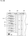
- FIG. 9A shows an example of the programming screen 200 when a non-movement command is not given
- FIG. 9B shows an example of the programming screen 200 when a non-movement command is given.
- command boxes 310 containing the movement command such as "straight line approach 1", “straight line deburr 1", “straight line depart 1”, are included in the command list area 300.
- These command boxes 310 i.e., teaching points
- the simulation bar 400 shows the time series sequence of the teaching points represented in the command list area 300.
- the detail confirmation bar 500 shows an enlarged time series sequence of the teaching points and intermediate points represented in the command list area 300.
- the simulation bar 400 shows the time series sequence of the movement commands in the command list area 300
- the detail confirmation bar 500 shows the time series sequence of the plurality of intermediate points between the multiple movement commands.
- the command box 310 containing the movement command such as "straight line approach 1", “straight line deburr 1", “straight line depart 1”, but the command box 310 containing a non-movement command, such as "signal output”, are included in that area.
- the timing of the signal output is between the teaching point of "straight line approach 3" and the teaching point of "straight line deburr 1".
- the signal output does not appear in the movement trajectory of the robot.
- the simulation bar 400 shows the time series sequence of the movement commands and non-movement commands in the command list area 300. In other words, in the simulation bar 400, the side part of the command box 310 of "signal output" indicates a non-movement command "signal output”.
- the non-movement command does not reflect to the detail confirmation bar 500.
- the detail confirmation bar 500 shows the time series sequence of the multiple intermediate points between the multiple movement commands, excluding the non-movement commands.
- the tick mark "026" is the teaching point of the movement command "straight line deburr 1”
- the tick mark "034" is the teaching point of the movement command "straight line deburr 2”.
- the command box 310 for a non-movement command "signal output” is inserted between the command box 310 for "straight line deburr 1" and the command box 310 for "straight line deburr 2".
- the detail confirmation bar 500 shown in FIG. 9B is the same as the detail confirmation bar 500 shown in FIG.9A . That is, in the detail confirmation bar 500 shown in FIG. 9B , a tick mark corresponding to the non-movement command "signal output" is not located between the tick mark "026" and the tick mark "034", which are both movement commands.
- the detail confirmation bar 500 does not reflect the non-movement command. Therefore, the detail confirmation bar 500 excludes non-movement commands that do not appear in the movement trajectory created by the simulation, and shows the teaching points and the intermediate points of the movement commands included in the movement trajectory. This allows providing the user with a detailed movement trajectory in time series order.
- FIG. 9C shows an example of the display form of the programming screen 200 when the pointer 411 points to the teaching point.
- the command box 310 of the selected teaching point in the command list area 300 is highlighted, and in the detail confirmation bar 500, the tick mark of the selected teaching point is also highlighted.
- the highlighting can be achieved, for example, by making the border of the command box 310 thicker, or the line of the tick mark on the detail confirmation bar 500 thicker.
- the highlighting may be done in other ways.
- the color of the command box 310 may change to a different color from other command boxes 310, or the line of the tick mark on the detail confirmation bar 500 may blink, etc. This can notify the user that a teaching point has been set at the selected point in time.
- the user may adjust the position of the pointer until the command box 310 and the line of the tick mark in the detail confirmation bar 500 are highlighted. When both are highlighted, the user can confirm the posture of the robot represented in the animation display area 600.
- the configuration and operation of the OLP system for the present disclosure is not limited to the above embodiments. Specifically, the thing to be displayed is not limited to the simulation bar 400 as long as it shows a time series sequence of multiple teaching points.
- the command box 310 in the section corresponding to the point in time when the error occurred may be displayed by the error color different from the color of the other command boxes, and the command box 310 in the section corresponding to the point in time when the warning event occurred may be displayed by the warning color different from the color of the other command boxes.
- the section when the error occurs may be indicated by an arrow or other symbol, or the tick mark of that section may be indicated by displaying (for example, blinking) differently from the tick mark of other sections.
- the first error display method is to display the partial area of the simulation bar 400 corresponding to the point in time when the error occurs with the error color, but is not limited to this.
- the partial area of the simulation bar 400 corresponding to the point in time when the error occurs may be displayed blinking.
- the second error display method is to display the partial area of the detail confirmation bar 500 corresponding to the point in time when the error occurs with the error color, but is not limited to this.
- the partial area of the detail confirmation bar 500 corresponding to the point in time when the error occurs may be displayed blinking.
- the OLP device 100 includes the input circuitry 101, the creation circuitry 102, the simulator 103, and the display 104.
- the input circuitry 101 receives input of a plurality of teaching points.
- the creation circuitry 102 determines one or more intermediate points located between adjacent teaching points and creates an operation program for the robot.
- the operation program includes the plurality of teaching points and intermediate point.
- the simulator 103 simulates the movement trajectory of the robot when the operation program is executed.
- the display 104 displays the programming screen 200 (GUI screen) representing the movement trajectory of the robot.
- the programming screen 200 includes the simulation bar 400 and the detail confirmation bar 500.
- the simulation bar 400 shows the time series sequence of the plurality of teaching points.
- the detail confirmation bar 500 shows a time series sequence of a plurality of the intermediate points between some of the plurality of teaching points included in the simulation bar 400 on a larger scale than the simulation bar 400.
- the simulation bar 400 can display the section between the teaching points by the first error display method.
- the section includes the point in time when the error occurs.
- the detail confirmation bar 500 can display the intermediate point corresponding to the point in time when the error occurs, by the second error display method.
- section between the teaching points may include the teaching points at both ends, or exclude the teaching points at both ends.
- “Section between the teaching points” may be a section including the teaching point at one end and not including the teaching point at the other end. As long as the intermediate point corresponding to the point in time when the error occurs is indicated by the second error display method, only the intermediate point may be indicated by the second error display, or the section including the intermediate point may be indicated by the second error display.
- the intermediate point corresponding to the point in time when the error occurs is indicated by the second error display method.
- the user can be notified of the error between the teaching points.
- the input circuitry 101 may receive input of the command including a teaching point and an instruction of the movement direction of the robot at the teaching point.
- the programming screen 200 may include the command list area 300.
- the plurality of command boxes 310 symbols
- the simulation bar 400 is located parallel to the row of the command boxes 310 in the command list area 300.
- the simulation bar 400 may be able to display the teaching point at which an error occurs in a manner corresponding to the command box 310 in the command list area 300.
- the teaching point where the error occurs is indicated in the simulation bar 400.
- the user can easily understand in which command the error occurs. In other words, the user can easily identify the command that should be corrected.
- the simulation bar 400 may include a linear section parallel to the row of the command boxes 310 in the command list area 300.
- the first error display method may be a method in which the portion of the linear section in which the error occurs is displayed in the error color.
- the error can be displayed while the area of the simulation bar 400 parallel to the command list area 300 is reduced.
- a portion of the simulation bar 400 may be able to be selected by the user.
- the time series sequence of the plurality of intermediate points in the portion selected by the user in the simulation bar 400 may be able to be displayed at a larger scale than in the simulation bar 400.
- the user when the user selects the portion of the simulation bar 400 that the user wishes to review in detail, the user can be provided with detailed information on the selected portion.
- the display 104 may be able to display the point in time selected in the simulation bar 400 by the user, in the detail confirmation bar 500, in a different manner than other points in time.
- the input circuitry 101 may be able to receive an instruction to add a command in a state where the user selects a portion of the simulation bar 400.
- the creation circuitry 102 may create the operation program again by adding a teaching point at the point in time selected by the user in the simulation bar 400 when the creation circuitry receives the instruction to add the command.
- the display 104 may be able to display the teaching point at the selected point in time in the detail confirmation bar 500, in a different manner than the other teaching points.
- the first error display method may be a method in which, when the error occurs between two adjacent teaching points, the section between the two teaching points on the simulation bar 400 is displayed with the error color.
- the first error display method also may be a method in which, when the error occurs at one teaching point, the section between the two teaching points that sandwich the one teaching point in the simulation bar 400 is displayed in the error color.
- the second error display method may be a method in which the section between a plurality of the intermediate points including the point where the error occurs in the detail confirmation bar 500 is displayed in the error color.
- the section including the teaching point corresponding to the point in time when the warning event occurs may be able to be displayed in the simulation bar 400, in the warning color.
- the first error region 420 When the first error region 420 overlaps with the first warning region 430, the first error region 420 may be able to be displayed in the error color, and the portion of the first warning region 430 except for the portion overlapping the first error region 420 may be able to be displayed in the warning color.
- the input circuitry 101 may be able to receive input both a plurality of movement commands that define the posture and the movement direction of the robot at each point in time and a non-movement command that does not define the posture and the movement direction of the robot.
- the simulation bar 400 may display a time series sequence including the teaching points for each of the multiple movement commands and including the non-movement command. When a section including some of the plurality of the teaching points and the non-movement command included in the simulation bar 400 is displayed in the detail confirmation bar 500, a time series sequence of the plurality of intermediate points between the plurality of teaching points excluding the non-movement command in this section may be able to be displayed in the detail confirmation bar 500.
- a second teaching point that does not appear in the movement trajectory generated by the simulation is not displayed, and first teaching points and the intermediate points included in the movement trajectory are displayed. Therefore, the detailed movement trajectory can be provided to the user in time series order.
Landscapes
- Engineering & Computer Science (AREA)
- Human Computer Interaction (AREA)
- Manufacturing & Machinery (AREA)
- Physics & Mathematics (AREA)
- General Physics & Mathematics (AREA)
- Automation & Control Theory (AREA)
- Robotics (AREA)
- Mechanical Engineering (AREA)
- Numerical Control (AREA)
- Manipulator (AREA)
- Finish Polishing, Edge Sharpening, And Grinding By Specific Grinding Devices (AREA)
Abstract
Description
- This disclosure relates to an offline programming device and an offline programming method.
- Offline programming in which a program that defines the movement of a robot is created without using an actual robot, is known.
PTL 1 discloses a method for creating a robot operation program by arranging icons each of which represents a command to a robot in order of movement using a GUI (graphical user interface). In the method disclosed inPTL 1, when placing an icon by the program creator on the program is detected, the operation program up to the placed icon is automatically simulated. If an error is detected by the simulation, a message indicating that the icon are inoperable and the reason for the inoperability is displayed. - PTL 1:
Japanese Patent Application Laid-Open 2008-142788 - In the offline programming (hereinafter referred to as "OLP"), when a user inputs teaching points that define movement points of the robot to an OLP device, it creates a program that connects the teaching points which are input. In the method disclosed in
PTL 1, icons, i.e., teaching point, at which an error occurs, can be displayed. However, it cannot output error information between teaching points. - The present invention is made in view of the circumstances described above, and an object of the present invention is to provide an offline programming device and an offline programming method in which a user can understand an error that occurs between teaching points.
- The offline programming device according to an aspect of the present invention includes: an input circuitry that receives input of a plurality of teaching points; a creation circuitry that determines one or more intermediate points located between adjacent teaching points and creates an operation program for a robot, the operation program including the plurality of teaching points and the intermediate point; the simulator that simulates a movement trajectory of the robot when the operation program is executed; and the display that displays a GUI screen representing the movement trajectory. The GUI screen includes a first display area showing a time series sequence of the plurality of teaching points and a second display area showing a time series sequence of a plurality of the intermediate points between some of the plurality of teaching points included in the first display area on a larger scale than the first display area. When an error is detected in the movement trajectory, the first display area can display a section between the teaching points, the section including a point in time when the error occurs, by a first error display method, and the second display area can display the intermediate point corresponding to the point in time when the error occurs, by a second error display method.
- An offline programming method according to an aspect of the present disclosure includes: a step of receiving input of a plurality of teaching points; a step of determining one or more intermediate points located between adjacent teaching points and creating an operation program for a robot, the operation program including the plurality of teaching points and the intermediate point; and a step of simulating a movement trajectory of the robot when the operation program is executed; and a step of displaying a GUI screen representing the movement trajectory. The GUI screen includes a first display area showing a time series sequence of the plurality of teaching points and a second display area showing a time series sequence of a plurality of the intermediate points between some of the plurality of teaching points included in the first display area on a larger scale than the first display area. When an error is detected in the movement trajectory, the first display area can display a section between the teaching points, the section including a point in time when the error occurs, by a first error display method, and the second display area can display the intermediate point corresponding to the point in time when the error occurs, by a second error display method.
- By the above offline programming device and offline programming method, in the second display area, the intermediate point corresponding to the point in time when the error occurs is displayed by the second error display method. Thus, the error occurs between the teaching points can be notified to the user.
- The present invention can be realized not only as an offline programming device and an offline programming method provided with the characteristic configuration described above, but also as a computer program for causing a computer to execute the characteristic steps in the offline programming method. Part or all of the offline programming device can be realized as a semiconductor integrated circuit, or as an offline programming system including the offline programming device.
- According to the invention, an error occurs between teaching points can be notified to the user.
-
-
FIG. 1 is a block diagram showing an example of a configuration of an offline programming device according to an embodiment. -
FIG. 2 is a functional block diagram showing the example of functions of the offline programming device according to the embodiment. - [
FIG. 3A ] Part of a flowchart showing an example of an operation procedure of the offline programming device according to the embodiment. - [
FIG. 3B ] Another part of the flowchart showing the example of the operation procedure of the offline programming device according to the embodiment. -
FIG. 4 is a diagram showing an example of a programming screen according to the embodiment. -
FIG. 5 is a diagram showing an example of a programming screen including a detail confirmation bar. - [
FIG. 6A ] A diagram showing an example of a change in the display of the detail confirmation bar. - [
FIG. 6B ] A diagram showing an example of a change in the display of the detail confirmation bar. - [
FIG. 7A ] A diagram showing an example of a display form of the simulation bar when an error occurs between two adjacent teaching points. - [
FIG. 7B ] A diagram showing an example of a display form of the simulation bar when an error occurs at the teaching point. - [
FIG. 8A ] A diagram showing an example of a display form of the simulation bar when an error and a warning event occur. - [
FIG. 8B ] A diagram showing another example of the display of the simulation bar when an error and a warning event occur. - [
FIG. 9A ] A diagram showing an example of the programming screen when the second teaching point is not given. - [
FIG. 9B ] A diagram showing an example of the programming screen when the second teaching point is given. - [
FIG. 9C ] A diagram showing an example of a display form of the programming screen when a teaching point is selected. - The details of the embodiments of the present invention will be described with reference to the drawings. At least a part of the embodiment described below may be combined as desired.
- An offline programming device of this embodiment is a device for creating a program that defines a movement of a robot without being connected to the actual robot. The robot is a vertically articulated robot in one example, a horizontally articulated robot in another example, and a parallel link robot in yet another example.
-
FIG. 1 is a block diagram of an example configuration of the offline programming device. TheOLP device 100 is configured, for example, by a computer. TheOLP device 100 has aprocessor 110, anon-transient memory 120, atransient memory 130, an input/output interface 140, aninput device 150, and adisplay device 160. - The
transient memory 130 is a volatile memory, for example, an SRAM (Static Random Access Memory), a DRAM (Dynamic Random Access Memory), or the like. Thenon-transient memory 120 is a non-volatile memory, for example, a flash memory, a hard disk, a ROM (Read Only Memory), or the like. Thenon-transient memory 120 stores anOLP program 170 as a computer program and data used for execute theOLP program 170. - The
OLP device 100 includes a computer. TheOLP program 170 as the computer program stored in the memory device of the computer is executed by theprocessor 110 as a CPU so that each function of theOLP device 100 is performed. TheOLP program 170 can be stored in a recording medium, for example, a flash memory, a ROM, a CD-ROM or the like. Theprocessor 110 executes theOLP program 170 and displays a programming screen as described later. - The
processor 110 is not limited to a CPU. Theprocessor 110 can be a hardware logic circuit, for example, an ASIC (Application Specific Integrated Circuit (ASIC), a gate array, a field programmable gate array (FPGA) or the like. In this case, the hardware logic circuit is configured to perform the same processing as theOLP program 170. - The input/
output interface 140 is connected by theinput device 150 and thedisplay device 160. Theinput device 150 is, for example, a keyboard, a mouse, a touchpad, a pen tablet or the like, and is used by the user to input data into theOLP device 100. Thedisplay device 160 is a liquid crystal panel or an organic EL (Electro Luminescence) panel, and can display text information, images, and the like in response to a command. The input/output interface 140 is compliant with, for example, USB (Universal Serial Bus), or HDMI (High-Definition Multimedia Interface; "HDMI" is a registered trademark). The input/output interface 140 can receive data from theinput device 150 and output data for display to thedisplay device 160. -
FIG. 2 is a functional block diagram showing an example of the functions of theOLP device 100 according to this embodiment. TheOLP device 100 has functions as aninput circuitry 101, acreation circuitry 102, asimulator 103, and adisplay 104. - The
input circuitry 101 receives a command that defines a movement of the robot at a certain point in time, input from the user. The command includes a teaching point that defines the posture of the robot, i.e., the movement point, a movement direction of the robot, such as a straight line, a circular arc, etc., and a type of work to be performed by the robot, such as deburring, welding, moving, etc. The user can input time series commands at multiple points in time to theinput circuitry 101. - The
creation circuitry 102, based on the commands received via theinput circuitry 101, determines one or more intermediate points connecting adjacent teaching points, and creates an operation program for the robot that includes the plurality of the teaching points and the intermediate points. When the operation program is executed on the robot which is an actual machine, the robot moves according to the movement trajectory in accordance with the time series commands. - The
simulator 103 simulates the movement trajectory of the robot when the operation program is executed. In other words, thesimulator 103 computes the movement trajectory of the robot in a three-dimensional virtual space. - The
simulator 103 can detect an error about the movement trajectory. Here, "error" includes an event that the computed movement trajectory cannot be realized. The error can include interference between robot components or between a robot component and another object, or an abnormal movement that exceeds the allowable range, for example, a movement in which the movement speed exceeds the maximum output of the motor or a movement that deviates from the movable range. When detecting the error, thesimulator 103 can identify the point in time when the error occurs. - Furthermore, the
simulator 103 can detect an event that requires warning to the user (warning event) about the movement trajectory. Here, "warning event" refers to an event that the computed movement trajectory can be realized but meets a specific warning condition. The warning condition may include, for example, a movement in which the movement speed is equal to or below the maximum output of the motor but above a specified value, an approach that exceeds the allowable range with respect to another object, or the like. When detecting the warning event, thesimulator 103 can identify the point in time when the warning event occurs. - The
display 104 displays a programming screen for creating an operation program. The programming screen is also a GUI screen that the movement trajectory is represented. The programming screen will be described later. -
FIGS. 3A and3B are flowcharts showing an example of the operation procedure of the offline programming device according to this embodiment. - When the
OLP program 170 starts, theprocessor 110 executes each of the following processes. First, the programming screen is displayed on the display device 160 (step S101). Since no commands have been registered at this time, the programming screen in its initial state, which does not include icons, images (video), and the like, is displayed. - The user can input a command to the
OLP device 100 by theinput device 150. Theprocessor 110 receives the command input from the user (step S102). In addition, theprocessor 110 adds a command block, which is a symbol (icon) indicating the command which is input, to the command list area, which is one area included in the programming screen (step S103). -
FIG. 4 shows an example of the programming screen. Theprogramming screen 200 includes acommand list area 300, asimulation bar 400, and ananimation display area 600. In thecommand list area 300, a plurality ofcommand boxes 310 are arranged in a row in time series order. In other words, in thecommand list area 300, thecommand boxes 310 are arranged in the order in which the commands are executed. - Refer again to
FIG. 3A . On the programming screen, once all the commands necessary to create the operation program have been input, the user can instruct the start of the simulation. Theprocessor 110 determines whether the instruction to start the simulation is received or not (step S104). - If the instruction to start the simulation is not received (NO in step S104), the
processor 110 executes step S102. This allows additional input of the command. If the instruction to start the simulation is received (YES in step S104), theprocessor 110 creates an operation program for the robot based on the input commands (step S105). Furthermore, theprocessor 110 executes the simulation (step S106). That is, theprocessor 110 simulates the movement trajectory when the operation program specified by the input command is executed. - When the simulation is completed, the
processor 110 displays a simulation bar on the display device 160 (step S107) and displays an animation of the movement trajectory generated by the simulation (step S108). - Refer again to
FIG. 4 . Thesimulation bar 400 is provided on the side of thecommand list area 300. Thesimulation bar 400 is located parallel to the row of thecommand boxes 310 in thecommand list area 300. Thesimulation bar 400 is a linear section parallel to the row of thecommand boxes 310. - The
simulation bar 400 corresponds to thecommand boxes 310 in thecommand list area 300. In other words, a portion beside (the right of) each of thecommand boxes 310 in the simulation bar 400 (a portion which is the same position vertically as eachcommand box 310, in the simulation bar 400) corresponds to eachcommand box 310. For example, in the example inFIG. 4 , a portion of thesimulation bar 400, which is beside thecommand box 310 containing the text "straight line approach 1", corresponds to thiscommand box 310. - The
simulation bar 400 has a length equals to or greater than the length of the row in which thecommand boxes 310 displayed in thecommand list area 300 arranged. This means that thesimulation bar 400 corresponds to all thecommand boxes 310 displayed in thecommand list area 300. - The
simulation bar 400 is displayed in a color (for example, white) that is different from an error color and from a warning color. If an error is detected, the portion of thesimulation bar 400 corresponding to the point in time when the error occurs is displayed in the error color (for example, red). Hereinafter, the portion of thesimulation bar 400 that is displayed in the error color is referred to as afirst error region 420. - Since each part of the
simulation bar 400 corresponds to thecommand box 310, thefirst error region 420 indicates the teaching point near the point in time of occurrence of the error. In the example inFIG. 4 , thefirst error region 420 is located in a range from thecommand box 310 containing the text "straight line deburr 1" to thecommand box 310 containing the text "straight line deburr 2". Therefore, it is understood that the error occurs in the range from the teaching point of thecommand box 310 containing the text "straight line deburr 1" to the teaching point of thecommand box 310 containing the text "straight line deburr 2". - If a warning event is detected, the portion of the
simulation bar 400 corresponding to the point in time when the warning event occurs is displayed in the warning color (for example, yellow). Hereafter, the portion of thesimulation bar 400 that is displayed in the warning color is referred to as thefirst warning region 430. - Since each part of the
simulation bar 400 corresponds to thecommand box 310, thefirst warning region 430 indicates the teaching point near the point in time of occurrence of the warning event. In the example inFIG. 4 , thefirst warning region 430 is located in a range from thecommand box 310 containing the text "straight line deburr 3" to thecommand box 310 containing the text "straight line depart 1". Therefore, it is understood that the warning event occurs in the range from the teaching point of thecommand box 310 containing the text "straight line deburr 3" to the teaching point of thecommand box 310 containing the text "straight line depart 1". - The
animation display area 600 displays the movement trajectory of the robot when the operation program is executed on thedisplay device 160, with animation (graphical display is performed). The animation allows the user to visually confirm the movement trajectory of the robot. - Refer again to
FIG. 3A . The user can select any one point on thesimulation bar 400. For example, the user can select a point on thesimulation bar 400 by moving the mouse pointer to the point and clicking, or by touching the position corresponding to the above-described point with a finger or a pen on a touchpad or a pen tablet. - The
processor 110 determines whether a selection of a point on thesimulation bar 400 from the user is received (step S109). If a selection of the point is not received from the user (NO in step S109), the processing by theOLP device 100 ends. If a selection of the point is received on thesimulation bar 400 from the user is received (YES in step S109), theprocessor 110 displays a detail confirmation bar on the display device 160 (step S110). -
FIG. 5 shows an example of the programming screen including the detail confirmation bar. When a point on thesimulation bar 400 is selected, apointer 411 is displayed at the position of the selected point, and adetail confirmation bar 500 is displayed on the side of thesimulation bar 400. The detail confirmation bar (second display area) 500 is displayed in part of theanimation display area 600. - The
detail confirmation bar 500 shows a time series sequence of a plurality of intermediate points between adjacent teaching points. In thedetail confirmation bar 500, the time series sequence of the intermediate points in the section before and after the selected point in thesimulation bar 400 is shown on a larger scale than thesimulation bar 400. In other words, thedetail confirmation bar 500 can display detailed information that cannot be displayed on thesimulation bar 400. - In a specific example, the
detail confirmation bar 500 includes tick marks indicating each of one or more teaching points and a plurality of intermediate points. For example, the tick mark for the intermediate point is represented by a thin line and the tick mark for the teaching point is represented by a thick line. In other words, in thedetail confirmation bar 500, the intermediate point and the teaching point are displayed distinguishable from each other. - The
detail confirmation bar 500 is displayed in a color (for example, black) that is different from the error color and from the warning color. If an error is detected, the portion of thedetail confirmation bar 500 corresponding to the point in time when the error occurs is displayed in the error color. Hereinafter, the portion of thedetail confirmation bar 500 that is displayed in the error color is referred to as asecond error region 520. - Since the
detail confirmation bar 500 shows a time series sequence of the intermediate points, thesecond error region 520 indicates the intermediate point near the point in time of occurrence of the error. In the example inFIG. 5 , thesecond error region 520 is located in a range from the intermediate point of the tick mark "027" to the intermediate point of the tick mark "029". Therefore, it is understood that the error occurs in the range. This allows the user to roughly identify the point in time when the error occurs by thesimulation bar 400, and to identify the point in time when the error occurs in detail by thedetail confirmation bar 500. - If the warning event is detected, the portion of the
detail confirmation bar 500 corresponding to the point in time when the warning event occurs is displayed in the warning color. Hereinafter, the portion of thedetail confirmation bar 500 that is displayed in the warning color is referred to as a second warning region. Since thedetail confirmation bar 500 shows a time series sequence of the intermediate points, the second warning region indicates the intermediate point near the point in time of occurrence of the warning event. In the example inFIG. 5 , although the second warning region is outside the display section of thedetail confirmation bar 500 and is not shown, but is displayed in the same form as thesecond error region 520. This allows the user to roughly identify the point in time when the warning event occurs by thesimulation bar 400, and to identify the point in time when the warning event occurs in detail by thedetail confirmation bar 500. - Refer
FIG. 3B . The user can slide thepointer 411 along thesimulation bar 400. For example, the user can slide thepointer 411 by dragging or swiping with thepointer 411 selected. As thepointer 411 slides, the point selected on thesimulation bar 400 is changed. - The
processor 110 determines whether a change of the selection point on thesimulation bar 400 from the user is received (step S111). If the change of the selection point from the user is not received (NO in step Sill), theprocessor 110 changes the process to be executed to step S113. If the change of the selection point from the user is received (YES in step Sill), theprocessor 110 makes thedisplay device 160 change the display of the detail confirmation bar 500 (step S112). -
FIGS. 6A and6B show one example of the change in the display of thedetail confirmation bar 500.FIGS. 6A and6B show before and after the change in the display of thedetail confirmation bar 500. As shown inFIGS. 6A and6B , anindicator 511 is displayed at the vertical center of thedetail confirmation bar 500, for indicating the selection point. The point in time indicated by theindicator 511 is the same as the point in time selected by thepointer 411. That is, the point in time selected by thepointer 411 and indicated on thesimulation bar 400 is the same as the point in time indicated by theindicator 511 on thedetail confirmation bar 500. Theindicator 511 is displayed fixedly. That is, theindicator 511 is always located at the vertical center of thedetail confirmation bar 500, and the position of theindicator 511 does not change even if thepointer 411 is slid. - As an example is shown in
FIGS. 6A and6B , when thepointer 411 is slid, the section indicated by thedetail confirmation bar 500 is changed according to the change in position of thepointer 411. In other words, inFIG. 6A , thedetail confirmation bar 500 indicates the section from the tick mark "021" to the tick mark "039", inFIG. 6B , thedetail confirmation bar 500 indicates the section from the tick mark "013" to the tick mark "032". In this way, the section displayed by thedetail confirmation bar 500 changes according to the change of the selection point by the user. Therefore, the user can slide thepointer 411 to display the detailed information of the section he/she wants to check on thedetail confirmation bar 500. In the examples shown inFIGS. 6A and6B , theindicator 511 is a dashed line extending horizontally, but it is not limited to this. For example, theindicator 511 may be a solid line extending horizontally, or it may be a circle, an arrow, or other symbol. - When the
pointer 411 is slid and the section indicated by thedetail confirmation bar 500 is changed, the position of thesecond error region 520 is changed as a result of the above-described change. Thesecond error region 520 appears in the section where the error occurs in thedetail confirmation bar 500. Therefore, when the position of thepointer 411 is changed and the display section of thedetail confirmation bar 500 is changed, the position of thesecond error region 520 changes by the same amount as the change in the display section and in the same direction as the change in the display section. If part or all of thesecond error region 520 changes to deviate from the display range of thedetail confirmation bar 500, the part or all of thesecond error region 520 is not displayed in thedetail confirmation bar 500. Likewise, the position of the second warning region also changes as the display section of thedetail confirmation bar 500 changes. - Refer again to
FIG. 3B . The user may edit the operation program and change a part of the movement trajectory of the robot. For example, if an error occurs where a part of the robot interferes with another object, the user changes the movement trajectory to avoid the interference. In theOLP device 100 in this embodiment, the user can use thedetail confirmation bar 500 to edit the operation program. - The user adds a new command to edit the operation program. In this case, the user can adjust the
pointer 411 to the point in time at which he/she wishes to add a command, and instruct theOLP device 100 to add a new command at that point in time. For example, the user confirm that one intermediate point is selected on thedetail confirmation bar 500, and then give an instruction to add a command to that intermediate point to theOLP device 100. - The instruction to add a command can be realized by various methods. For example, a button for adding a command may be displayed in the
command list area 300, and the user may select the button to instruct to add a command. Furthermore, a drop-down list containing multiple items may be displayed in response to a click or touch operation on theprogramming screen 200, and the user may select the "add command" item in the drop-down list to instruct to add a command. - The
processor 110 determines whether the instruction to add a command from the user is received or not (step S113). If the instruction to add a command is not received (NO in step S113), theprocessor 110 advances the process to be executed to step S116. On the other hand, if the instruction to add a command is received (YES in step S113), theprocessor 110 adds the command to the point in time that is currently selected (step S114). In adding a command, a teaching point is set at the selected point in time. Moreover, the movement direction of the robot and the type of work included in the new command are specified by the user. - The
processor 110 determines whether the instruction to start the simulation is received or not (step S115). If the instruction to start the simulation is not received (YES in step S115), theprocessor 110 changes the process to be executed to step S105. As a result, an operation program containing the added command is created and the simulation is executed. - On the other hand, if the instruction to start the simulation is not received (NO in step S115), the
processor 110 determines whether an instruction to end the processes is received from the user or not (step S116). If the instruction to end is not received (NO in step S116), theprocessor 110 changes the process to be executed to step S111. If the instruction to quit of the processes from the user is received (YES in step S116), theprocessor 110 ends the process of theOLP program 170. This concludes the processing by theOLP device 100. - The
programming screen 200, in particular thesimulation bar 400 and thedetail confirmation bar 500 have various display embodiments. Examples of the display embodiments of theprogramming screen 200 will be described below. - The
simulation bar 400 changes its display form depending on the point in time when the error or the warning event occurs. More specifically, the display form thesimulation bar 400 varies depending on whether the error or the warning event occurs between two adjacent teaching points or at a teaching point. -
FIGS. 7A and7B illustrate the display forms of the simulation bar depending on the point in time when the error occurs.FIG. 7A shows an example of the display form of thesimulation bar 400 when the error occurs between two adjacent teaching points.FIG. 7B shows an example of the display form of thesimulation bar 400 when the error occurs at a teaching point. - If the error occurs between two adjacent teaching points, i.e., if the error occurs at an intermediate point or in a section containing multiple intermediate points (but excluding teaching points), the
first error region 420 is located in the section between two adjacent teaching points that sandwich the point in time when the error occurs, as shown inFIG. 7A . Here, "section between two teaching points" may include the teaching points at both ends or may exclude the teaching points at both ends. "Section between two teaching points" may be a section including the teaching point at one end and not including the teaching point at the other end. In the example inFIG. 7A , thefirst error region 420 is located in a section between the teaching point at thecommand box 310 for "straight line deburr 1" and the teaching point at thecommand box 310 for "straight line deburr 2". As a result, the user can understand that the error occurs between the teaching point of "straight line deburr 1" and the teaching point of "straight line deburr 2". - The
detail confirmation bar 500 indicates an error occurrence point in a more detailed manner. In other words, in thedetail confirmation bar 500, thesecond error region 520 is located in a smaller section than thefirst error region 420 in thesimulation bar 400. Thesecond error region 520 is provided in a section between a plurality of intermediate points including the point in time at which the error occurs. For example, when an error occurs during a period of time including multiple intermediate points, thesecond error region 520 is located in that period of time of thedetail confirmation bar 500. In other examples, when an error occurs at an intermediate point, thesecond error region 520 is located in a section including the intermediate point, for example, in a section between intermediate points (or teaching points) of both sides each of which is adjacent to the intermediate point. - If the error occurs at one teaching point, i.e., if the error occurs at only one teaching point, or if the error occurs in a section including one teaching point (but not including the other teaching points), the
first error region 420 is located in a section over three consecutive teaching points, as shown inFIG. 7B . The three consecutive teaching points are the teaching point at the time the error occurred and the two teaching points of both sides that are adjacent to it. In the example inFIG. 7B , thefirst error region 420 is located in a section over the teaching point of thecommand box 310 for "straight line approach 3", the teaching point of thecommand box 310 for "straight line deburr 1", and the teaching point of thecommand box 310 for "straight line deburr 2". This allows the user to understand that the error occurs at the teaching point of "straight line deburr 1". - In this case, the
detail confirmation bar 500 also indicates an error occurrence point in a more detailed manner. For example, if an error occurs at only one teaching point, thesecond error region 520 is located in a section including the teaching point, for example, a section between the intermediate points of both sides each of which is adjacent to this teaching point. In another example, if an error occurs in a period of time that includes one teaching point and one or more intermediate points, thesecond error region 520 is located in that period of time in thedetail confirmation bar 500. - If both of an error and a warning event occur in the movement trajectory of the robot, the
first error region 420 and thefirst warning region 430 is provided in thesimulation bar 400, respectively.FIG. 8A shows an example of the display form of the simulation bar when an error and a warning event occur, andFIG. 8B shows another example. -
FIG. 8A shows an example in which thefirst error region 420 and thefirst warning region 430 are far from each other. As described above, thefirst error region 420 and the first warning region appear in the section defined by the point in time of occurrence of the error and the warning event. When thefirst error region 420 and thefirst warning region 430 do not overlap, i.e. when thefirst error region 420 and thefirst warning region 430 are in contact (the teaching point at one end of thefirst error region 420 is the same as the teaching point at the other end of the first warning region), or when thefirst error region 420 and thefirst warning region 430 are far from each other, each of thefirst error region 420 and thefirst warning region 430 is displayed entirely. - In the example in
FIG. 8A , the error occurs in the section between the teaching point of thecommand box 310 for "straight line approach 3" and the teaching point of thecommand box 310 for "straight line deburr 1", and the warning event occurs in the section between the teaching point of thecommand box 310 for "straight line deburr 2" and the teaching point of thecommand box 310 for "straight line deburr 3". In this case, thefirst error region 420 is located in a section between the teaching point of thecommand box 310 for "straight line approach 3" and the teaching point of thecommand box 310 for "straight line deburr 1", and thefirst warning region 430 is located in a section between the teaching points of thecommand box 310 for "straight line deburr 2" and the teaching points of thecommand box 310 for "straight line deburr 3". In this example, thefirst error region 420 and thefirst warning region 430 are far from each other. -
FIG. 8B shows an example in which thefirst error region 420 and thefirst warning region 430 partially overlap each other in thesimulation bar 400. When thefirst error region 420 and thefirst warning region 430 overlap each other at least in part, thefirst error region 420 is displayed being given priority. In other words, the range thefirst error region 420 and the first warning region overlap is displayed as thefirst error region 420 and not as thefirst warning region 430. - In the example in
FIG. 8B , the error occurs in the section between the teaching point of thecommand box 310 for "straight line approach 3" and the teaching point of thecommand box 310 for "straight line deburr 1", and the warning event occurs at the teaching point of thecommand box 310 for "straight line deburr 1". In this case, the section between the teaching point of thecommand box 310 for "straight line approach 3" and the teaching point of thecommand box 310 for "straight line deburr 1" can be considered to be thefirst error region 420, and the section between the teaching point of thecommand box 310 for "straight line approach 3" and the teaching point of thecommand box 310 for "straight line deburr 2" can be considered to be thefirst warning region 430. However, thefirst error region 420 and thefirst warning region 430 overlap each other in the section between the teaching point of thecommand box 310 for "straight line approach 3" and the teaching point of thecommand box 310 for "straight line deburr 1". Therefore, thefirst error region 420 is displayed in this section. - The teaching point described above is a command (movement command) that defines the posture and the movement of the robot. In other words, the command described above includes the teaching point defining the posture of the robot, i.e., the movement point, the movement direction of the robot, such as a straight line or a circular arc, and the type of work to be performed by the robot, such as deburring, welding, or moving. In programming for operation of the robot, a command that does not define the posture of the robot (non-movement command) may be given. For example, inputting or outputting a control signal to or from the robot, setting a standby time of the robot, calling a subprogram, changing a precision of the movement, and setting the machining position of the end effector attached at the end of the arm of the robot are non-movement commands.
- The
programming screen 200 in the case where the non-movement command as described above is given will be described.FIG. 9A shows an example of theprogramming screen 200 when a non-movement command is not given, andFIG. 9B shows an example of theprogramming screen 200 when a non-movement command is given. - In the example of
FIG. 9A , only thecommand boxes 310 containing the movement command, such as "straight line approach 1", "straight line deburr 1", "straight line depart 1", are included in thecommand list area 300. These command boxes 310 (i.e., teaching points) are arranged in time series order, and thesimulation bar 400 shows the time series sequence of the teaching points represented in thecommand list area 300. Thedetail confirmation bar 500 shows an enlarged time series sequence of the teaching points and intermediate points represented in thecommand list area 300. In other words, thesimulation bar 400 shows the time series sequence of the movement commands in thecommand list area 300, and thedetail confirmation bar 500 shows the time series sequence of the plurality of intermediate points between the multiple movement commands. - In the example of
FIG. 9B , not only thecommand boxes 310 containing the movement command, such as "straight line approach 1", "straight line deburr 1", "straight line depart 1", but thecommand box 310 containing a non-movement command, such as "signal output", are included in that area. The timing of the signal output is between the teaching point of "straight line approach 3" and the teaching point of "straight line deburr 1". However, the signal output does not appear in the movement trajectory of the robot. Thesimulation bar 400 shows the time series sequence of the movement commands and non-movement commands in thecommand list area 300. In other words, in thesimulation bar 400, the side part of thecommand box 310 of "signal output" indicates a non-movement command "signal output". - The non-movement command does not reflect to the
detail confirmation bar 500. In other words, thedetail confirmation bar 500 shows the time series sequence of the multiple intermediate points between the multiple movement commands, excluding the non-movement commands. In the examples inFIGS. 9A and9B , with respect to thedetail confirmation bar 500, the tick mark "026" is the teaching point of the movement command "straight line deburr 1", and the tick mark "034" is the teaching point of the movement command "straight line deburr 2". In the example inFIG. 9B , thecommand box 310 for a non-movement command "signal output" is inserted between thecommand box 310 for "straight line deburr 1" and thecommand box 310 for "straight line deburr 2". However, thedetail confirmation bar 500 shown inFIG. 9B is the same as thedetail confirmation bar 500 shown inFIG.9A . That is, in thedetail confirmation bar 500 shown inFIG. 9B , a tick mark corresponding to the non-movement command "signal output" is not located between the tick mark "026" and the tick mark "034", which are both movement commands. - Thus, the
detail confirmation bar 500 does not reflect the non-movement command. Therefore, thedetail confirmation bar 500 excludes non-movement commands that do not appear in the movement trajectory created by the simulation, and shows the teaching points and the intermediate points of the movement commands included in the movement trajectory. This allows providing the user with a detailed movement trajectory in time series order. - When checking the movement trajectory of the robot or changing the operation program, it is convenient if the user can check what posture the robot takes at the teaching point. The
OLP device 100 of this embodiment provides a function for checking the posture of the robot at the teaching point in order to support programming.FIG. 9C shows an example of the display form of theprogramming screen 200 when thepointer 411 points to the teaching point. - In the example shown in
FIG. 9C , when thepointer 411 points to one teaching point, thecommand box 310 of the selected teaching point in thecommand list area 300 is highlighted, and in thedetail confirmation bar 500, the tick mark of the selected teaching point is also highlighted. The highlighting can be achieved, for example, by making the border of thecommand box 310 thicker, or the line of the tick mark on thedetail confirmation bar 500 thicker. However, the highlighting may be done in other ways. For example, the color of thecommand box 310 may change to a different color fromother command boxes 310, or the line of the tick mark on thedetail confirmation bar 500 may blink, etc. This can notify the user that a teaching point has been set at the selected point in time. The user may adjust the position of the pointer until thecommand box 310 and the line of the tick mark in thedetail confirmation bar 500 are highlighted. When both are highlighted, the user can confirm the posture of the robot represented in theanimation display area 600. - The configuration and operation of the OLP system for the present disclosure is not limited to the above embodiments. Specifically, the thing to be displayed is not limited to the
simulation bar 400 as long as it shows a time series sequence of multiple teaching points. - For example, in the
simulation bar 400, instead of indicating the section when the error occurred by thefirst error region 420 and indicating the section when the warning event occurred by thefirst warning region 430, in thecommand list area 300, thecommand box 310 in the section corresponding to the point in time when the error occurred may be displayed by the error color different from the color of the other command boxes, and thecommand box 310 in the section corresponding to the point in time when the warning event occurred may be displayed by the warning color different from the color of the other command boxes. Although thesimulation bar 400 is provided, instead of thefirst error region 420 and thefirst warning region 430, the section when the error occurs may be indicated by an arrow or other symbol, or the tick mark of that section may be indicated by displaying (for example, blinking) differently from the tick mark of other sections. - In the above embodiment, the first error display method is to display the partial area of the
simulation bar 400 corresponding to the point in time when the error occurs with the error color, but is not limited to this. For example, the partial area of thesimulation bar 400 corresponding to the point in time when the error occurs may be displayed blinking. In the above embodiment, the second error display method is to display the partial area of thedetail confirmation bar 500 corresponding to the point in time when the error occurs with the error color, but is not limited to this. For example, the partial area of thedetail confirmation bar 500 corresponding to the point in time when the error occurs may be displayed blinking. - As described above, the
OLP device 100 includes theinput circuitry 101, thecreation circuitry 102, thesimulator 103, and thedisplay 104. Theinput circuitry 101 receives input of a plurality of teaching points. Thecreation circuitry 102 determines one or more intermediate points located between adjacent teaching points and creates an operation program for the robot. The operation program includes the plurality of teaching points and intermediate point. Thesimulator 103 simulates the movement trajectory of the robot when the operation program is executed. Thedisplay 104 displays the programming screen 200 (GUI screen) representing the movement trajectory of the robot. Theprogramming screen 200 includes thesimulation bar 400 and thedetail confirmation bar 500. Thesimulation bar 400 shows the time series sequence of the plurality of teaching points. Thedetail confirmation bar 500 shows a time series sequence of a plurality of the intermediate points between some of the plurality of teaching points included in thesimulation bar 400 on a larger scale than thesimulation bar 400. When the error is detected in the movement trajectory, thesimulation bar 400 can display the section between the teaching points by the first error display method. The section includes the point in time when the error occurs. Thedetail confirmation bar 500 can display the intermediate point corresponding to the point in time when the error occurs, by the second error display method. Here, "section between the teaching points" may include the teaching points at both ends, or exclude the teaching points at both ends. "Section between the teaching points" may be a section including the teaching point at one end and not including the teaching point at the other end. As long as the intermediate point corresponding to the point in time when the error occurs is indicated by the second error display method, only the intermediate point may be indicated by the second error display, or the section including the intermediate point may be indicated by the second error display. - With the above configuration, in the
detail confirmation bar 500, the intermediate point corresponding to the point in time when the error occurs is indicated by the second error display method. Thus, the user can be notified of the error between the teaching points. - The
input circuitry 101 may receive input of the command including a teaching point and an instruction of the movement direction of the robot at the teaching point. Theprogramming screen 200 may include thecommand list area 300. In thecommand list area 300, the plurality of command boxes 310 (symbols), respectively indicating a plurality of the commands, are arranged in a row. Thesimulation bar 400 is located parallel to the row of thecommand boxes 310 in thecommand list area 300. Thesimulation bar 400 may be able to display the teaching point at which an error occurs in a manner corresponding to thecommand box 310 in thecommand list area 300. - As a result, according to the
command box 310 lined up in thecommand list area 300, the teaching point where the error occurs is indicated in thesimulation bar 400. Thus, the user can easily understand in which command the error occurs. In other words, the user can easily identify the command that should be corrected. - The
simulation bar 400 may include a linear section parallel to the row of thecommand boxes 310 in thecommand list area 300. The first error display method may be a method in which the portion of the linear section in which the error occurs is displayed in the error color. - Accordingly, the error can be displayed while the area of the
simulation bar 400 parallel to thecommand list area 300 is reduced. - A portion of the
simulation bar 400 may be able to be selected by the user. In thedetail confirmation bar 500, the time series sequence of the plurality of intermediate points in the portion selected by the user in thesimulation bar 400 may be able to be displayed at a larger scale than in thesimulation bar 400. - Accordingly, when the user selects the portion of the
simulation bar 400 that the user wishes to review in detail, the user can be provided with detailed information on the selected portion. - The
display 104 may be able to display the point in time selected in thesimulation bar 400 by the user, in thedetail confirmation bar 500, in a different manner than other points in time. - This allows the user to understand the point in time selected by the user in the
detail confirmation bar 500 while it is distinguished from other points in time. - The
input circuitry 101 may be able to receive an instruction to add a command in a state where the user selects a portion of thesimulation bar 400. Thecreation circuitry 102 may create the operation program again by adding a teaching point at the point in time selected by the user in thesimulation bar 400 when the creation circuitry receives the instruction to add the command. - This allows the user to add a new command by precisely specifying intermediate point that is more detailed than the teaching point.
- When the point in time selected by the user in the
simulation bar 400 coincides with a point in time corresponding to one teaching point, thedisplay 104 may be able to display the teaching point at the selected point in time in thedetail confirmation bar 500, in a different manner than the other teaching points. - This allows the user to be notified that the point in time corresponding to the teaching point is selected.
- The first error display method may be a method in which, when the error occurs between two adjacent teaching points, the section between the two teaching points on the
simulation bar 400 is displayed with the error color. - This allows the user to identify in which of the multiple sections between the multiple teaching points the error occurs.
- The first error display method also may be a method in which, when the error occurs at one teaching point, the section between the two teaching points that sandwich the one teaching point in the
simulation bar 400 is displayed in the error color. - This allows the user to identify at which of the multiple teaching points the error occurs. Furthermore, since the section between the teaching points adjacent to the teaching point where the error occurs is displayed in the error color, the area where the error color is displayed is larger than when only the teaching point where the error occurs is highlighted. Therefore, the user can recognize the section easily.
- The second error display method may be a method in which the section between a plurality of the intermediate points including the point where the error occurs in the
detail confirmation bar 500 is displayed in the error color. - This allows the user to be notified of the detailed occurrence point of the error by a finer section than between the teaching points.
- When the warning event is detected in the movement trajectory, the section including the teaching point corresponding to the point in time when the warning event occurs may be able to be displayed in the
simulation bar 400, in the warning color. - This allows the user to be notified of the occurrence point of the warning event, which is more minor than the error, as distinct from the error occurrence point.
- When the
first error region 420 overlaps with thefirst warning region 430, thefirst error region 420 may be able to be displayed in the error color, and the portion of thefirst warning region 430 except for the portion overlapping thefirst error region 420 may be able to be displayed in the warning color. - This allows the section of occurrence of the error, being more important than the section of occurrence of the warning event, can be displayed with priority over the section of occurrence of the warning event.
- The
input circuitry 101 may be able to receive input both a plurality of movement commands that define the posture and the movement direction of the robot at each point in time and a non-movement command that does not define the posture and the movement direction of the robot. Thesimulation bar 400 may display a time series sequence including the teaching points for each of the multiple movement commands and including the non-movement command. When a section including some of the plurality of the teaching points and the non-movement command included in thesimulation bar 400 is displayed in thedetail confirmation bar 500, a time series sequence of the plurality of intermediate points between the plurality of teaching points excluding the non-movement command in this section may be able to be displayed in thedetail confirmation bar 500. - Accordingly, in the
detail confirmation bar 500, a second teaching point that does not appear in the movement trajectory generated by the simulation is not displayed, and first teaching points and the intermediate points included in the movement trajectory are displayed. Therefore, the detailed movement trajectory can be provided to the user in time series order. - The embodiments disclosed here are in all respects illustrative and not restrictive. The scope of the invention is indicated by the claims, not by the embodiments described above, and includes all modifications within the meaning and scope of the claims and equivalents thereto.
-
- 100
- Offline programming device
- 101
- Input circuitry
- 102
- Creation circuitry
- 103
- Simulator
- 104
- Display
- 110
- Processor
- 120
- Non-transient memory
- 130
- Transient memory
- 140
- Input/output interface
- 150
- Input device
- 160
- Display device
- 170
- OLP program
- 200
- Programming screen (GUI screen)
- 300
- Command list area
- 310
- Command box (symbol)
- 400
- Simulation bar (first display area)
- 411
- Pointer
- 420
- First error region
- 430
- First warning region
- 500
- Detail confirmation bar (second display area)
- 511
- Indicator
- 520
- Second error region
- 600
- Animation display area
Claims (14)
- An offline programming device comprising:an input circuitry that receives input of a plurality of teaching points;a creation circuitry that determines one or more intermediate points located between adjacent teaching points and creates an operation program for a robot, the operation program including the plurality of teaching points and the intermediate point;the simulator that simulates a movement trajectory of the robot when the operation program is executed; andthe display that displays a GUI screen representing the movement trajectory, whereinthe GUI screen includes a first display area showing a time series sequence of the plurality of teaching points and a second display area showing a time series sequence of a plurality of the intermediate points between some of the plurality of teaching points included in the first display area on a larger scale than the first display area, andwhen an error is detected in the movement trajectory, the first display area can display a section between the teaching points, the section including a point in time when the error occurs, by a first error display method, and the second display area can display the intermediate point corresponding to the point in time when the error occurs, by a second error display method.
- The offline programming device according to claim 1, whereinthe input circuitry receives input of a command including the teaching point and an indication of a movement direction of the robot at the teaching point,the GUI screen includes a command list area in which a plurality of symbols respectively indicating a plurality of the commands are arranged in a row,the first display area is located parallel to the row of the symbols in the command list area, andthe first display area can display the teaching point at which an error occurs in a manner corresponding to the symbol in the command list area.
- The offline programming device according to claim 2, whereinthe first display area includes a linear section parallel to the row of the symbols in the command list area, andthe first error display method is a method in which a portion of the linear section in which the error occurs is displayed in a specific color.
- The offline programming device according to any one of claims 1 to 3, whereina portion of the first display area can be selected by a user, andin the second display area, a time series sequence of the plurality of intermediate points in the portion selected by the user in the first display area can be displayed at a larger scale than in the first display area.
- The offline programming device according to claim 4, wherein
the display can display the point in time selected in the first display area by the user, in the second display area in a different method than the other points in time. - The offline programming device according to claim 4 or 5, whereinthe input circuitry can receive an instruction to add a command in a state where the user selects a portion of the first display area, andthe creation circuitry creates the operation program again by adding a teaching point at the point in time selected by the user in the first display area when the creation circuitry receives the instruction to add the command.
- The offline programming device according to any one of claims 4 to 6, wherein
when the point in time selected by the user in the first display area coincides with a point in time corresponding to one teaching point, the display can display the one teaching point in the second display area in a different manner than the other teaching point. - The offline programming device according to any one of claims 1 to 7, wherein
the first error display method is a method in which, when an error occurs between two adjacent teaching points, a section between the two teaching points in the first display area is displayed in a specific color. - The offline programming device according to any one of claims 1 to 8, wherein
the first error display method is a method in which, when an error occurs at one teaching point, a section between the two teaching points that sandwich the one teaching point in the first display area is displayed in a specific color. - The offline programming device according to claim 8 or 9, wherein
the second error display method is a method in which a section between a plurality of the intermediate points including a point where the error occurs in the second display area is displayed in a specific color. - The offline programming device according to any one of claims 8 to 10, wherein
when an event requiring a warning to the user is detected in the movement trajectory, a section including the teaching point corresponding to a point in time when the event occurs is displayed in the first display area, in a specific warning color different from the specific color. - The offline programming device according to claim 11, wherein
when a first section to be displayed in the specific color overlaps a second section to be displayed in the warning color, the first section is displayed in the specific color and a portion of the second section except for a portion overlapping the first section can be displayed in the warning color. - The offline programming device according to any one of claims 1 to 12, whereinthe input circuitry receives input of a plurality of movement commands that define a posture and a movement direction of the robot at each point in time, and receives input of a non-movement command that does not define the posture and the movement direction of the robot,the first display area displays a time series sequence of the teaching points for each of the multiple movement commands and the non-movement command, andwhen a section including some of the plurality of teaching points and the non-movement command which are included in the first display area is displayed in the second display area, a time series sequence of the plurality of intermediate points between the plurality of teaching points excluding the non-movement command in the section can be displayed in the second display area.
- An offline programming method comprising:a step of receiving input of a plurality of teaching points;a step of determining one or more intermediate points located between adjacent teaching points and creating an operation program for a robot, the operation program including the plurality of teaching points and the intermediate point;a step of simulating a movement trajectory of the robot when the operation program is executed; anda step of displaying a GUI screen representing the movement trajectory, whereinthe GUI screen includes a first display area showing a time series sequence of the plurality of teaching points and a second display area showing a time series sequence of a plurality of the intermediate points between some of the plurality of teaching points included in the first display area on a larger scale than the first display area, andwhen an error is detected in the movement trajectory, the first display area can indicate a section between the teaching points, the section including a point in time when the error occurs, by a first error display method, and the second display area can indicate the intermediate point corresponding to the point in time when the error occurs, by a second error display method.
Applications Claiming Priority (2)
| Application Number | Priority Date | Filing Date | Title |
|---|---|---|---|
| JP2019227276A JP7382217B2 (en) | 2019-12-17 | 2019-12-17 | Offline programming device and offline programming method |
| PCT/JP2020/046831 WO2021125192A1 (en) | 2019-12-17 | 2020-12-15 | Offline programming device and offline programming method |
Publications (2)
| Publication Number | Publication Date |
|---|---|
| EP4079465A1 true EP4079465A1 (en) | 2022-10-26 |
| EP4079465A4 EP4079465A4 (en) | 2024-01-03 |
Family
ID=76430096
Family Applications (1)
| Application Number | Title | Priority Date | Filing Date |
|---|---|---|---|
| EP20901449.7A Pending EP4079465A4 (en) | 2019-12-17 | 2020-12-15 | Offline programming device and offline programming method |
Country Status (5)
| Country | Link |
|---|---|
| US (1) | US12253843B2 (en) |
| EP (1) | EP4079465A4 (en) |
| JP (1) | JP7382217B2 (en) |
| CN (1) | CN115210047B (en) |
| WO (1) | WO2021125192A1 (en) |
Cited By (1)
| Publication number | Priority date | Publication date | Assignee | Title |
|---|---|---|---|---|
| US12275147B2 (en) | 2022-02-08 | 2025-04-15 | Daihen Corporation | Robot teaching system |
Families Citing this family (2)
| Publication number | Priority date | Publication date | Assignee | Title |
|---|---|---|---|---|
| US12076868B2 (en) * | 2020-04-08 | 2024-09-03 | Robim Technologies Inc. Of Canada | Cloud based computer-implemented visually programming method and system for robotic motions in construction |
| TW202232261A (en) * | 2021-01-14 | 2022-08-16 | 日商發那科股份有限公司 | Robot teaching device and robot program generation program |
Family Cites Families (21)
| Publication number | Priority date | Publication date | Assignee | Title |
|---|---|---|---|---|
| JP2518178B2 (en) * | 1987-06-03 | 1996-07-24 | 株式会社安川電機 | Program display method for checking mutual interference of robots |
| JPH07104698B2 (en) * | 1988-02-26 | 1995-11-13 | 本田技研工業株式会社 | Circular interpolation method of teaching data in robot |
| JPH06266547A (en) * | 1993-03-15 | 1994-09-22 | Tokyo Electric Co Ltd | Data processor |
| KR100959280B1 (en) * | 2002-05-17 | 2010-05-26 | 오쿠마 가부시키가이샤 | Tool trajectory display method of NC data and NC data analysis method |
| JP2007331196A (en) * | 2006-06-14 | 2007-12-27 | Murata Mach Ltd | Image forming apparatus |
| JP2008142788A (en) | 2006-12-06 | 2008-06-26 | Yaskawa Electric Corp | Operation program creation support method and operation program creation apparatus. |
| US7974828B2 (en) * | 2007-04-27 | 2011-07-05 | Omron Corporation | Simulation device for programmable controller |
| CN100524117C (en) * | 2007-11-12 | 2009-08-05 | 上海神明控制工程有限公司 | Flame detecting interconnected monitoring system |
| US8539447B2 (en) | 2008-06-04 | 2013-09-17 | Microsoft Corporation | Real-time validation of interactive applications |
| JP6050004B2 (en) * | 2012-02-07 | 2016-12-21 | 株式会社ダイヘン | Arc welding monitor |
| JP6282140B2 (en) | 2014-02-26 | 2018-02-21 | キヤノン株式会社 | Orbit generation method, robot apparatus, program, and recording medium |
| US9278449B1 (en) | 2014-05-21 | 2016-03-08 | Bot & Dolly, Llc | Closed-loop control system for robotic operation |
| JP6350037B2 (en) * | 2014-06-30 | 2018-07-04 | 株式会社安川電機 | Robot simulator and robot simulator file generation method |
| CN105415375B (en) * | 2016-01-02 | 2017-04-05 | 宁波市智能制造产业研究院 | A kind of robot Off-line Programming System |
| EP3472677A1 (en) * | 2016-06-20 | 2019-04-24 | Hypertherm, Inc | Systems and methods for planning paths to guide robots |
| JP6469162B2 (en) * | 2017-04-17 | 2019-02-13 | ファナック株式会社 | Offline teaching device for robots |
| JP7095262B2 (en) | 2017-11-10 | 2022-07-05 | 株式会社安川電機 | Programming support device, robot system and program generation method |
| CN108280784A (en) * | 2017-12-19 | 2018-07-13 | 深圳市因尚网络科技股份有限公司 | Operation feedback method, equipment and computer readable storage medium |
| JP7146402B2 (en) | 2018-01-18 | 2022-10-04 | キヤノン株式会社 | Information processing device and information processing method |
| JP6838017B2 (en) * | 2018-08-31 | 2021-03-03 | ファナック株式会社 | Teaching device, teaching method, and teaching program for laser machining |
| US12440984B2 (en) * | 2020-05-25 | 2025-10-14 | Fanuc Corporation | Offline teaching device and motion-program generation method |
-
2019
- 2019-12-17 JP JP2019227276A patent/JP7382217B2/en active Active
-
2020
- 2020-12-15 US US17/786,636 patent/US12253843B2/en active Active
- 2020-12-15 CN CN202080087031.9A patent/CN115210047B/en active Active
- 2020-12-15 EP EP20901449.7A patent/EP4079465A4/en active Pending
- 2020-12-15 WO PCT/JP2020/046831 patent/WO2021125192A1/en not_active Ceased
Cited By (1)
| Publication number | Priority date | Publication date | Assignee | Title |
|---|---|---|---|---|
| US12275147B2 (en) | 2022-02-08 | 2025-04-15 | Daihen Corporation | Robot teaching system |
Also Published As
| Publication number | Publication date |
|---|---|
| US12253843B2 (en) | 2025-03-18 |
| EP4079465A4 (en) | 2024-01-03 |
| JP2021094644A (en) | 2021-06-24 |
| CN115210047B (en) | 2025-09-16 |
| JP7382217B2 (en) | 2023-11-16 |
| US20230030278A1 (en) | 2023-02-02 |
| CN115210047A (en) | 2022-10-18 |
| WO2021125192A1 (en) | 2021-06-24 |
Similar Documents
| Publication | Publication Date | Title |
|---|---|---|
| US20230267690A1 (en) | Information processing apparatus and control method of display apparatus | |
| US12253843B2 (en) | Offline programming device and offline programming method | |
| US8739038B2 (en) | Floating action buttons | |
| TWI541713B (en) | Apparatus for creating ladder program | |
| JP6867457B2 (en) | Information processing device | |
| CN113868726B (en) | Editor for creating and editing feature control frames for geometry and tolerances | |
| US20250091206A1 (en) | Teaching device | |
| CN110737244A (en) | Numerical controller and data editing method | |
| EP3674887B1 (en) | User interface development assistance device, user interface development assistance method, and user interface development assistance program | |
| US20150032419A1 (en) | Plc designing apparatus | |
| JP3359562B2 (en) | Display screen creation method for programmable display device | |
| US10354034B1 (en) | System and method for tuning a graphical highlight set to improve hierarchical layout editing | |
| JP2020170266A (en) | Ladder display device | |
| KR101522200B1 (en) | Method and apparatus for dispalying electronic documents displaying calculation results in one or more calculation result region | |
| TW202514293A (en) | Programming device | |
| WO2024028977A1 (en) | Teaching device | |
| JP2007086979A (en) | Test pattern editing device | |
| JPWO2012114523A1 (en) | Design apparatus, design method, and design program | |
| KR20210053288A (en) | Improved touch detection selection | |
| KR20140124154A (en) | Method for correcting steel materials collecting data and erp system for the method |
Legal Events
| Date | Code | Title | Description |
|---|---|---|---|
| STAA | Information on the status of an ep patent application or granted ep patent |
Free format text: STATUS: THE INTERNATIONAL PUBLICATION HAS BEEN MADE |
|
| PUAI | Public reference made under article 153(3) epc to a published international application that has entered the european phase |
Free format text: ORIGINAL CODE: 0009012 |
|
| STAA | Information on the status of an ep patent application or granted ep patent |
Free format text: STATUS: REQUEST FOR EXAMINATION WAS MADE |
|
| 17P | Request for examination filed |
Effective date: 20220713 |
|
| AK | Designated contracting states |
Kind code of ref document: A1 Designated state(s): AL AT BE BG CH CY CZ DE DK EE ES FI FR GB GR HR HU IE IS IT LI LT LU LV MC MK MT NL NO PL PT RO RS SE SI SK SM TR |
|
| DAV | Request for validation of the european patent (deleted) | ||
| DAX | Request for extension of the european patent (deleted) | ||
| A4 | Supplementary search report drawn up and despatched |
Effective date: 20231204 |
|
| RIC1 | Information provided on ipc code assigned before grant |
Ipc: G05B 19/4069 20060101ALI20231128BHEP Ipc: G05B 19/42 20060101ALI20231128BHEP Ipc: G05B 19/4068 20060101ALI20231128BHEP Ipc: B25J 9/22 20060101AFI20231128BHEP |