EP4079430A1 - Cutting tool - Google Patents
Cutting tool Download PDFInfo
- Publication number
- EP4079430A1 EP4079430A1 EP20931972.2A EP20931972A EP4079430A1 EP 4079430 A1 EP4079430 A1 EP 4079430A1 EP 20931972 A EP20931972 A EP 20931972A EP 4079430 A1 EP4079430 A1 EP 4079430A1
- Authority
- EP
- European Patent Office
- Prior art keywords
- hard carbon
- carbon film
- base body
- cutting tool
- sample
- Prior art date
- Legal status (The legal status is an assumption and is not a legal conclusion. Google has not performed a legal analysis and makes no representation as to the accuracy of the status listed.)
- Granted
Links
Images




Classifications
-
- B—PERFORMING OPERATIONS; TRANSPORTING
- B23—MACHINE TOOLS; METAL-WORKING NOT OTHERWISE PROVIDED FOR
- B23B—TURNING; BORING
- B23B27/00—Tools for turning or boring machines; Tools of a similar kind in general; Accessories therefor
- B23B27/14—Cutting tools of which the bits or tips or cutting inserts are of special material
-
- C—CHEMISTRY; METALLURGY
- C23—COATING METALLIC MATERIAL; COATING MATERIAL WITH METALLIC MATERIAL; CHEMICAL SURFACE TREATMENT; DIFFUSION TREATMENT OF METALLIC MATERIAL; COATING BY VACUUM EVAPORATION, BY SPUTTERING, BY ION IMPLANTATION OR BY CHEMICAL VAPOUR DEPOSITION, IN GENERAL; INHIBITING CORROSION OF METALLIC MATERIAL OR INCRUSTATION IN GENERAL
- C23C—COATING METALLIC MATERIAL; COATING MATERIAL WITH METALLIC MATERIAL; SURFACE TREATMENT OF METALLIC MATERIAL BY DIFFUSION INTO THE SURFACE, BY CHEMICAL CONVERSION OR SUBSTITUTION; COATING BY VACUUM EVAPORATION, BY SPUTTERING, BY ION IMPLANTATION OR BY CHEMICAL VAPOUR DEPOSITION, IN GENERAL
- C23C30/00—Coating with metallic material characterised only by the composition of the metallic material, i.e. not characterised by the coating process
- C23C30/005—Coating with metallic material characterised only by the composition of the metallic material, i.e. not characterised by the coating process on hard metal substrates
-
- C—CHEMISTRY; METALLURGY
- C04—CEMENTS; CONCRETE; ARTIFICIAL STONE; CERAMICS; REFRACTORIES
- C04B—LIME, MAGNESIA; SLAG; CEMENTS; COMPOSITIONS THEREOF, e.g. MORTARS, CONCRETE OR LIKE BUILDING MATERIALS; ARTIFICIAL STONE; CERAMICS; REFRACTORIES; TREATMENT OF NATURAL STONE
- C04B41/00—After-treatment of mortars, concrete, artificial stone or ceramics; Treatment of natural stone
- C04B41/009—After-treatment of mortars, concrete, artificial stone or ceramics; Treatment of natural stone characterised by the material treated
-
- C—CHEMISTRY; METALLURGY
- C04—CEMENTS; CONCRETE; ARTIFICIAL STONE; CERAMICS; REFRACTORIES
- C04B—LIME, MAGNESIA; SLAG; CEMENTS; COMPOSITIONS THEREOF, e.g. MORTARS, CONCRETE OR LIKE BUILDING MATERIALS; ARTIFICIAL STONE; CERAMICS; REFRACTORIES; TREATMENT OF NATURAL STONE
- C04B41/00—After-treatment of mortars, concrete, artificial stone or ceramics; Treatment of natural stone
- C04B41/45—Coating or impregnating, e.g. injection in masonry, partial coating of green or fired ceramics, organic coating compositions for adhering together two concrete elements
- C04B41/50—Coating or impregnating, e.g. injection in masonry, partial coating of green or fired ceramics, organic coating compositions for adhering together two concrete elements with inorganic materials
- C04B41/5001—Coating or impregnating, e.g. injection in masonry, partial coating of green or fired ceramics, organic coating compositions for adhering together two concrete elements with inorganic materials with carbon or carbonisable materials
-
- C—CHEMISTRY; METALLURGY
- C04—CEMENTS; CONCRETE; ARTIFICIAL STONE; CERAMICS; REFRACTORIES
- C04B—LIME, MAGNESIA; SLAG; CEMENTS; COMPOSITIONS THEREOF, e.g. MORTARS, CONCRETE OR LIKE BUILDING MATERIALS; ARTIFICIAL STONE; CERAMICS; REFRACTORIES; TREATMENT OF NATURAL STONE
- C04B41/00—After-treatment of mortars, concrete, artificial stone or ceramics; Treatment of natural stone
- C04B41/45—Coating or impregnating, e.g. injection in masonry, partial coating of green or fired ceramics, organic coating compositions for adhering together two concrete elements
- C04B41/52—Multiple coating or impregnating multiple coating or impregnating with the same composition or with compositions only differing in the concentration of the constituents, is classified as single coating or impregnation
-
- C—CHEMISTRY; METALLURGY
- C22—METALLURGY; FERROUS OR NON-FERROUS ALLOYS; TREATMENT OF ALLOYS OR NON-FERROUS METALS
- C22C—ALLOYS
- C22C29/00—Alloys based on carbides, oxides, nitrides, borides, or silicides, e.g. cermets, or other metal compounds, e.g. oxynitrides, sulfides
- C22C29/02—Alloys based on carbides, oxides, nitrides, borides, or silicides, e.g. cermets, or other metal compounds, e.g. oxynitrides, sulfides based on carbides or carbonitrides
- C22C29/06—Alloys based on carbides, oxides, nitrides, borides, or silicides, e.g. cermets, or other metal compounds, e.g. oxynitrides, sulfides based on carbides or carbonitrides based on carbides, but not containing other metal compounds
- C22C29/08—Alloys based on carbides, oxides, nitrides, borides, or silicides, e.g. cermets, or other metal compounds, e.g. oxynitrides, sulfides based on carbides or carbonitrides based on carbides, but not containing other metal compounds based on tungsten carbide
-
- C—CHEMISTRY; METALLURGY
- C23—COATING METALLIC MATERIAL; COATING MATERIAL WITH METALLIC MATERIAL; CHEMICAL SURFACE TREATMENT; DIFFUSION TREATMENT OF METALLIC MATERIAL; COATING BY VACUUM EVAPORATION, BY SPUTTERING, BY ION IMPLANTATION OR BY CHEMICAL VAPOUR DEPOSITION, IN GENERAL; INHIBITING CORROSION OF METALLIC MATERIAL OR INCRUSTATION IN GENERAL
- C23C—COATING METALLIC MATERIAL; COATING MATERIAL WITH METALLIC MATERIAL; SURFACE TREATMENT OF METALLIC MATERIAL BY DIFFUSION INTO THE SURFACE, BY CHEMICAL CONVERSION OR SUBSTITUTION; COATING BY VACUUM EVAPORATION, BY SPUTTERING, BY ION IMPLANTATION OR BY CHEMICAL VAPOUR DEPOSITION, IN GENERAL
- C23C14/00—Coating by vacuum evaporation, by sputtering or by ion implantation of the coating forming material
- C23C14/0021—Reactive sputtering or evaporation
-
- C—CHEMISTRY; METALLURGY
- C23—COATING METALLIC MATERIAL; COATING MATERIAL WITH METALLIC MATERIAL; CHEMICAL SURFACE TREATMENT; DIFFUSION TREATMENT OF METALLIC MATERIAL; COATING BY VACUUM EVAPORATION, BY SPUTTERING, BY ION IMPLANTATION OR BY CHEMICAL VAPOUR DEPOSITION, IN GENERAL; INHIBITING CORROSION OF METALLIC MATERIAL OR INCRUSTATION IN GENERAL
- C23C—COATING METALLIC MATERIAL; COATING MATERIAL WITH METALLIC MATERIAL; SURFACE TREATMENT OF METALLIC MATERIAL BY DIFFUSION INTO THE SURFACE, BY CHEMICAL CONVERSION OR SUBSTITUTION; COATING BY VACUUM EVAPORATION, BY SPUTTERING, BY ION IMPLANTATION OR BY CHEMICAL VAPOUR DEPOSITION, IN GENERAL
- C23C14/00—Coating by vacuum evaporation, by sputtering or by ion implantation of the coating forming material
- C23C14/02—Pretreatment of the material to be coated
- C23C14/021—Cleaning or etching treatments
- C23C14/022—Cleaning or etching treatments by means of bombardment with energetic particles or radiation
-
- C—CHEMISTRY; METALLURGY
- C23—COATING METALLIC MATERIAL; COATING MATERIAL WITH METALLIC MATERIAL; CHEMICAL SURFACE TREATMENT; DIFFUSION TREATMENT OF METALLIC MATERIAL; COATING BY VACUUM EVAPORATION, BY SPUTTERING, BY ION IMPLANTATION OR BY CHEMICAL VAPOUR DEPOSITION, IN GENERAL; INHIBITING CORROSION OF METALLIC MATERIAL OR INCRUSTATION IN GENERAL
- C23C—COATING METALLIC MATERIAL; COATING MATERIAL WITH METALLIC MATERIAL; SURFACE TREATMENT OF METALLIC MATERIAL BY DIFFUSION INTO THE SURFACE, BY CHEMICAL CONVERSION OR SUBSTITUTION; COATING BY VACUUM EVAPORATION, BY SPUTTERING, BY ION IMPLANTATION OR BY CHEMICAL VAPOUR DEPOSITION, IN GENERAL
- C23C14/00—Coating by vacuum evaporation, by sputtering or by ion implantation of the coating forming material
- C23C14/02—Pretreatment of the material to be coated
- C23C14/024—Deposition of sublayers, e.g. to promote adhesion of the coating
-
- C—CHEMISTRY; METALLURGY
- C23—COATING METALLIC MATERIAL; COATING MATERIAL WITH METALLIC MATERIAL; CHEMICAL SURFACE TREATMENT; DIFFUSION TREATMENT OF METALLIC MATERIAL; COATING BY VACUUM EVAPORATION, BY SPUTTERING, BY ION IMPLANTATION OR BY CHEMICAL VAPOUR DEPOSITION, IN GENERAL; INHIBITING CORROSION OF METALLIC MATERIAL OR INCRUSTATION IN GENERAL
- C23C—COATING METALLIC MATERIAL; COATING MATERIAL WITH METALLIC MATERIAL; SURFACE TREATMENT OF METALLIC MATERIAL BY DIFFUSION INTO THE SURFACE, BY CHEMICAL CONVERSION OR SUBSTITUTION; COATING BY VACUUM EVAPORATION, BY SPUTTERING, BY ION IMPLANTATION OR BY CHEMICAL VAPOUR DEPOSITION, IN GENERAL
- C23C14/00—Coating by vacuum evaporation, by sputtering or by ion implantation of the coating forming material
- C23C14/06—Coating by vacuum evaporation, by sputtering or by ion implantation of the coating forming material characterised by the coating material
- C23C14/0605—Carbon
-
- C—CHEMISTRY; METALLURGY
- C23—COATING METALLIC MATERIAL; COATING MATERIAL WITH METALLIC MATERIAL; CHEMICAL SURFACE TREATMENT; DIFFUSION TREATMENT OF METALLIC MATERIAL; COATING BY VACUUM EVAPORATION, BY SPUTTERING, BY ION IMPLANTATION OR BY CHEMICAL VAPOUR DEPOSITION, IN GENERAL; INHIBITING CORROSION OF METALLIC MATERIAL OR INCRUSTATION IN GENERAL
- C23C—COATING METALLIC MATERIAL; COATING MATERIAL WITH METALLIC MATERIAL; SURFACE TREATMENT OF METALLIC MATERIAL BY DIFFUSION INTO THE SURFACE, BY CHEMICAL CONVERSION OR SUBSTITUTION; COATING BY VACUUM EVAPORATION, BY SPUTTERING, BY ION IMPLANTATION OR BY CHEMICAL VAPOUR DEPOSITION, IN GENERAL
- C23C14/00—Coating by vacuum evaporation, by sputtering or by ion implantation of the coating forming material
- C23C14/06—Coating by vacuum evaporation, by sputtering or by ion implantation of the coating forming material characterised by the coating material
- C23C14/0635—Carbides
-
- C—CHEMISTRY; METALLURGY
- C23—COATING METALLIC MATERIAL; COATING MATERIAL WITH METALLIC MATERIAL; CHEMICAL SURFACE TREATMENT; DIFFUSION TREATMENT OF METALLIC MATERIAL; COATING BY VACUUM EVAPORATION, BY SPUTTERING, BY ION IMPLANTATION OR BY CHEMICAL VAPOUR DEPOSITION, IN GENERAL; INHIBITING CORROSION OF METALLIC MATERIAL OR INCRUSTATION IN GENERAL
- C23C—COATING METALLIC MATERIAL; COATING MATERIAL WITH METALLIC MATERIAL; SURFACE TREATMENT OF METALLIC MATERIAL BY DIFFUSION INTO THE SURFACE, BY CHEMICAL CONVERSION OR SUBSTITUTION; COATING BY VACUUM EVAPORATION, BY SPUTTERING, BY ION IMPLANTATION OR BY CHEMICAL VAPOUR DEPOSITION, IN GENERAL
- C23C14/00—Coating by vacuum evaporation, by sputtering or by ion implantation of the coating forming material
- C23C14/22—Coating by vacuum evaporation, by sputtering or by ion implantation of the coating forming material characterised by the process of coating
- C23C14/24—Vacuum evaporation
- C23C14/32—Vacuum evaporation by explosion; by evaporation and subsequent ionisation of the vapours, e.g. ion-plating
- C23C14/325—Electric arc evaporation
-
- C—CHEMISTRY; METALLURGY
- C23—COATING METALLIC MATERIAL; COATING MATERIAL WITH METALLIC MATERIAL; CHEMICAL SURFACE TREATMENT; DIFFUSION TREATMENT OF METALLIC MATERIAL; COATING BY VACUUM EVAPORATION, BY SPUTTERING, BY ION IMPLANTATION OR BY CHEMICAL VAPOUR DEPOSITION, IN GENERAL; INHIBITING CORROSION OF METALLIC MATERIAL OR INCRUSTATION IN GENERAL
- C23C—COATING METALLIC MATERIAL; COATING MATERIAL WITH METALLIC MATERIAL; SURFACE TREATMENT OF METALLIC MATERIAL BY DIFFUSION INTO THE SURFACE, BY CHEMICAL CONVERSION OR SUBSTITUTION; COATING BY VACUUM EVAPORATION, BY SPUTTERING, BY ION IMPLANTATION OR BY CHEMICAL VAPOUR DEPOSITION, IN GENERAL
- C23C28/00—Coating for obtaining at least two superposed coatings either by methods not provided for in a single one of groups C23C2/00 - C23C26/00 or by combinations of methods provided for in subclasses C23C and C25C or C25D
- C23C28/04—Coating for obtaining at least two superposed coatings either by methods not provided for in a single one of groups C23C2/00 - C23C26/00 or by combinations of methods provided for in subclasses C23C and C25C or C25D only coatings of inorganic non-metallic material
-
- C—CHEMISTRY; METALLURGY
- C23—COATING METALLIC MATERIAL; COATING MATERIAL WITH METALLIC MATERIAL; CHEMICAL SURFACE TREATMENT; DIFFUSION TREATMENT OF METALLIC MATERIAL; COATING BY VACUUM EVAPORATION, BY SPUTTERING, BY ION IMPLANTATION OR BY CHEMICAL VAPOUR DEPOSITION, IN GENERAL; INHIBITING CORROSION OF METALLIC MATERIAL OR INCRUSTATION IN GENERAL
- C23C—COATING METALLIC MATERIAL; COATING MATERIAL WITH METALLIC MATERIAL; SURFACE TREATMENT OF METALLIC MATERIAL BY DIFFUSION INTO THE SURFACE, BY CHEMICAL CONVERSION OR SUBSTITUTION; COATING BY VACUUM EVAPORATION, BY SPUTTERING, BY ION IMPLANTATION OR BY CHEMICAL VAPOUR DEPOSITION, IN GENERAL
- C23C28/00—Coating for obtaining at least two superposed coatings either by methods not provided for in a single one of groups C23C2/00 - C23C26/00 or by combinations of methods provided for in subclasses C23C and C25C or C25D
- C23C28/04—Coating for obtaining at least two superposed coatings either by methods not provided for in a single one of groups C23C2/00 - C23C26/00 or by combinations of methods provided for in subclasses C23C and C25C or C25D only coatings of inorganic non-metallic material
- C23C28/044—Coating for obtaining at least two superposed coatings either by methods not provided for in a single one of groups C23C2/00 - C23C26/00 or by combinations of methods provided for in subclasses C23C and C25C or C25D only coatings of inorganic non-metallic material coatings specially adapted for cutting tools or wear applications
-
- C—CHEMISTRY; METALLURGY
- C23—COATING METALLIC MATERIAL; COATING MATERIAL WITH METALLIC MATERIAL; CHEMICAL SURFACE TREATMENT; DIFFUSION TREATMENT OF METALLIC MATERIAL; COATING BY VACUUM EVAPORATION, BY SPUTTERING, BY ION IMPLANTATION OR BY CHEMICAL VAPOUR DEPOSITION, IN GENERAL; INHIBITING CORROSION OF METALLIC MATERIAL OR INCRUSTATION IN GENERAL
- C23C—COATING METALLIC MATERIAL; COATING MATERIAL WITH METALLIC MATERIAL; SURFACE TREATMENT OF METALLIC MATERIAL BY DIFFUSION INTO THE SURFACE, BY CHEMICAL CONVERSION OR SUBSTITUTION; COATING BY VACUUM EVAPORATION, BY SPUTTERING, BY ION IMPLANTATION OR BY CHEMICAL VAPOUR DEPOSITION, IN GENERAL
- C23C28/00—Coating for obtaining at least two superposed coatings either by methods not provided for in a single one of groups C23C2/00 - C23C26/00 or by combinations of methods provided for in subclasses C23C and C25C or C25D
- C23C28/04—Coating for obtaining at least two superposed coatings either by methods not provided for in a single one of groups C23C2/00 - C23C26/00 or by combinations of methods provided for in subclasses C23C and C25C or C25D only coatings of inorganic non-metallic material
- C23C28/046—Coating for obtaining at least two superposed coatings either by methods not provided for in a single one of groups C23C2/00 - C23C26/00 or by combinations of methods provided for in subclasses C23C and C25C or C25D only coatings of inorganic non-metallic material with at least one amorphous inorganic material layer, e.g. DLC, a-C:H, a-C:Me, the layer being doped or not
-
- B—PERFORMING OPERATIONS; TRANSPORTING
- B23—MACHINE TOOLS; METAL-WORKING NOT OTHERWISE PROVIDED FOR
- B23B—TURNING; BORING
- B23B2226/00—Materials of tools or workpieces not comprising a metal
- B23B2226/12—Boron nitride
- B23B2226/125—Boron nitride cubic [CBN]
-
- B—PERFORMING OPERATIONS; TRANSPORTING
- B23—MACHINE TOOLS; METAL-WORKING NOT OTHERWISE PROVIDED FOR
- B23B—TURNING; BORING
- B23B2228/00—Properties of materials of tools or workpieces, materials of tools or workpieces applied in a specific manner
- B23B2228/10—Coatings
- B23B2228/105—Coatings with specified thickness
-
- C—CHEMISTRY; METALLURGY
- C04—CEMENTS; CONCRETE; ARTIFICIAL STONE; CERAMICS; REFRACTORIES
- C04B—LIME, MAGNESIA; SLAG; CEMENTS; COMPOSITIONS THEREOF, e.g. MORTARS, CONCRETE OR LIKE BUILDING MATERIALS; ARTIFICIAL STONE; CERAMICS; REFRACTORIES; TREATMENT OF NATURAL STONE
- C04B2111/00—Mortars, concrete or artificial stone or mixtures to prepare them, characterised by specific function, property or use
- C04B2111/00241—Physical properties of the materials not provided for elsewhere in C04B2111/00
- C04B2111/0025—Compositions or ingredients of the compositions characterised by the crystal structure
-
- Y—GENERAL TAGGING OF NEW TECHNOLOGICAL DEVELOPMENTS; GENERAL TAGGING OF CROSS-SECTIONAL TECHNOLOGIES SPANNING OVER SEVERAL SECTIONS OF THE IPC; TECHNICAL SUBJECTS COVERED BY FORMER USPC CROSS-REFERENCE ART COLLECTIONS [XRACs] AND DIGESTS
- Y10—TECHNICAL SUBJECTS COVERED BY FORMER USPC
- Y10T—TECHNICAL SUBJECTS COVERED BY FORMER US CLASSIFICATION
- Y10T428/00—Stock material or miscellaneous articles
- Y10T428/30—Self-sustaining carbon mass or layer with impregnant or other layer
Definitions
- the present disclosure relates to a cutting tool.
- Hard carbon films such as amorphous carbon and diamond-like carbon are used as coating materials for cutting tools, metal molds, and machine components because of their excellent wear resistance and lubricity.
- Patent Literature 1 discloses an amorphous carbon covered tool comprising a base body composed of WC base and an amorphous carbon film that covers the base body.
- Patent Literature 2 discloses a cutting tool equipped with a base body and a DLC layer positioned on the surface of the base body and containing diamond-like carbon.
- a cutting tool of the present disclosure is
- an object of the present disclosure is to provide a cutting tool that can have a long tool life even when used to cut soft metals in particular.
- Notations in the form of "A to B" as used herein mean the upper limit and lower limit of the range (that is, no less than A and no more than B), and when no unit is given in A but only in B, the unit in A is the same as the unit in B.
- FIG. 1 is a cross-sectional view of an example of the cutting tool according to the present embodiment.
- Fig. 2 is a cross-sectional view of another example of the cutting tool according to the present embodiment.
- a cutting tool 30 of the present embodiment comprises a base body 5 and a hard carbon film 20 arranged on base body 5, hard carbon film 20 including an amorphous phase 25 and a graphite phase 24, the density of hard carbon film 20 being no less than 2.5 g/cm 3 and no more than 3.5 g/cm 3 , the degree of crystallinity of hard carbon film 20 being no more than 6.5%, and the average coordination number of amorphous phase 25 being no less than 2.5 and no more than 4.
- the hard carbon film of the present embodiment can have a long tool life even when used to cut soft metals in particular. The reason for this is not clear, but may be presumed to be as in (i) to (iv) below.
- a cutting tool 31 of the present embodiment can comprise an interface layer 21 disposed between base body 5 and hard carbon film 20. It can also comprise, between base body 5 and interface layer 21, a mixed composition layer (not shown in the figure) in which the compositions of these films are mixed, or a gradient composition layer (not shown in the figure) in which the composition varies continuously. Furthermore, it can comprise an underlying layer (not shown in the figure) between base body 5 and interface layer 21 for improving the adhesiveness between them.
- Hard carbon film 20 may be arranged so as to cover the entire surface of base body 5, or it may be arranged so as to cover part of it.
- the hard carbon film is arranged so as to cover part of the base body, it is preferably arranged so as to cover at least the surface of a portion of the base body involved in cutting.
- the portion of the base body involved in cutting as used herein means a region in the base body bounded by its cutting edge ridge and a hypothetical plane at a distance of 2 mm from the cutting edge ridge to the base body side along the perpendicular line of the tangent line of the cutting edge ridge.
- metallic or ceramic base bodies can be used as base body 5.
- base bodies made of iron, heat-treated steel, WC-based cemented carbide, cermet, stainless steel, nickel, copper, aluminum alloys, titanium alloys, alumina, cubic boron nitride, and silicon carbide.
- Hard carbon film 20 includes amorphous phase 25 and graphite phase 24.
- graphite phase 24 is shown in the form of granules, but the shape of the graphite phase is not particularly limited.
- the shape of the graphite phase may be in the form of sheets, layers of overlapping sheets, or irregular shapes.
- the hard carbon film can consist only of the amorphous phase and the graphite phase.
- the density of hard carbon film 20 is no less than 2.5 g/cm 3 and no more than 3.5 g/cm 3 .
- the lower limit of the density of the hard carbon film is no less than 2.5 g/cm 3 , preferably no less than 2.8 g/cm 3 , and more preferably no less than 3.1 g/cm 3 .
- the upper limit of the density of the hard carbon film is no more than 3.5 g/cm 3 , and preferably no more than 3.4 g/cm 3 .
- the density of the hard carbon film is preferably no less than 3.0 g/cm 3 and no more than 3.5 g/cm 3 , and more preferably no less than 3.2 g/cm 3 and no more than 3.4 g/cm 3 .
- the density of the hard carbon film is measured by the X-ray reflectometry (measurement apparatus: "SmartLab” (TM) manufactured by Rigaku Corporation).
- the measurement conditions for the X-ray reflectometry are as follows.
- the degree of crystallinity of hard carbon film 20 is no more than 6.5%.
- the degree of crystallinity of the hard carbon film is an index that indicates the proportion of the graphite phase with respect to the amorphous phase in the hard carbon film on a volume basis. The smaller the degree of crystallinity, the lower the proportion of the graphite phase, which is of low hardness, and the higher the hardness of the hard carbon film.
- the degree of crystallinity of the hard carbon film is no more than 6.5%, the hardness of the hard carbon film is moderate and the hard carbon film can have excellent wear resistance.
- the upper limit of the degree of crystallinity of the hard carbon film is no more than 6.5%, preferably no more than 5.9%, and more preferably no more than 5.0%.
- the degree of crystallinity of the hard carbon film is preferably no less than 2% and no more than 6.5%, and still more preferably no less than 3% and no more than 5%.
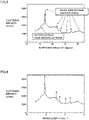
- Fig. 3 shows the X-ray diffraction pattern of an example of the hard carbon film of the present embodiment, and the shape of the X-ray diffraction pattern is not limited to this.
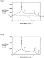
- FIG. 4 shows the X-ray diffraction pattern shown in Fig. 3 transformed so that the X axis indicates the wavenumber and the Y axis indicates the scattering intensity.
- FIG. 5 shows the region with a wavenumber of 1 to 3.6 ⁇ -1 extracted from the post-transform pattern shown in Fig. 4 , where the X axis indicates the wavenumber and the Y axis indicates the scattering intensity.
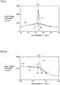
- Fig. 6 shows a pattern (hereinafter, also referred to as "normalized pattern") of a spectrum S21 (hereinafter, also referred to as "normalized spectrum”), which is obtained by normalizing spectrum S1 of the extracted pattern of Fig. 5 based on straight line L1, where the X axis indicates the wavenumber and the Y axis indicates the scattering intensity.
- FIG. 7 is a pattern showing the spectrum derived from the amorphous phase separated from the normalized pattern of Fig. 6 , where the X axis indicates the wavenumber and the Y axis indicates the scattering intensity.
- Fig. 8 is a pattern showing the peaks derived from the graphite phase separated from the normalized pattern of Fig. 6 , where the X axis indicates the wavenumber and the Y axis indicates the scattering intensity.
- Peak A11 is a peak that exists in the wavenumber range of 1.6 to 2.1 ⁇ -1 and originates from the (200) plane of the graphite phase.
- Peak A12 is a peak that exists in the wavenumber range of 2.9 to 3.2 ⁇ -1 and originates from the (011) plane of the graphite phase.
- Peak A13 is a peak that exists in the wavenumber range of 3.3 to 3.55 ⁇ -1 and originates from the (012) plane of the graphite phase.
- Fig. 9 shows the normalized pattern shown in Fig. 6 to describe the method for separating peak A11, where the X axis indicates the wavenumber and the Y axis indicates the scattering intensity.
- Intersection point a2 and the region with a wavenumber of 2.0 to 2.1 ⁇ -1 on spectrum S21 are approximated by a straight line, thereby obtaining an approximate straight line a3.
- Fig. 10 shows the normalized pattern shown in Fig. 6 to describe the method for separating peak A12, where the X axis indicates the wavenumber and the Y axis indicates the scattering intensity.
- an intersection point b2 of a perpendicular line L12 from the peak top of A12 and approximate straight line b1 is determined.
- Intersection point b2 and the region with a wavenumber of 3.15 to 3.2 ⁇ -1 on spectrum S21 are approximated by a straight line, thereby obtaining an approximate straight line b3.
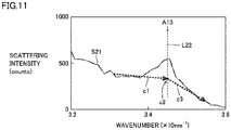
- Fig. 11 shows the normalized pattern shown in Fig. 6 to describe the method for separating peak A13, where the X axis indicates the wavenumber and the Y axis indicates the scattering intensity.
- Intersection point c2 and the region with a wavenumber of 3.5 to 3.55 ⁇ -1 on spectrum S21 are approximated by a straight line, thereby obtaining an approximate straight line c3.
- the average coordination number of amorphous phase 25 is no less than 2.5 and no more than 4. When the average coordination number of the amorphous phase is in this range, the hardness of the hard carbon film is moderate and the hard carbon film can have excellent wear resistance.
- the lower limit of the average coordination number of the amorphous phase is no less than 2.5, preferably no less than 3, and more preferably no less than 3.5.
- the upper limit of the average coordination number of the amorphous phase is no more than 4, and the average coordination number of the amorphous phase is more preferably no less than 3.5 and no more than 4.
- the average coordination number of the amorphous phase is calculated by the method described below. The details of the calculation method will be described with reference to Figs. 3 , 12 , and 13 .
- (C1) For the hard carbon film, X-ray diffraction measurement is carried out by the same method and conditions as the above (A1), thereby obtaining an X-ray diffraction pattern.
- An example of the X-ray diffraction pattern of a hard carbon film of a cutting tool according to one embodiment of the present disclosure is shown in Fig. 3 .
- the total correlation function is calculated from the obtained X-ray diffraction pattern.
- the total correlation function is calculated by carrying out correction for background and other factors on the spectrum obtained from the X-ray diffraction measurement, followed by Fourier transform.
- the total correlation function can be calculated based on descriptions in, for example, [Literature 1] Shiramata et al., "PDF Analysis Using X-Ray Total Scattering - Theory and Application Examples -", Rigaku Journal, Rigaku Corporation, 2019, 50(1), p. 1-8 , [Literature 2] K.
- Fig. 12 is a diagram showing the relationship between the measured interatomic distance calculated from the X-ray diffraction pattern of Fig. 3 and the total correlation function, as well as the relationship between the interatomic distance after fitting by the reverse Monte Carlo method and the total correlation function.
- the measured peak in the interatomic distance range of 0.130 to 0.185 nm is represented by P1.
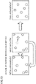
- Fig. 13 is a diagram for describing the reverse Monte Carlo method.
- the reverse Monte Carlo method is a simulation method in which the atoms present in a cubic cell with the density of the target substance are moved using random numbers to determine a structure model that reproduces experimental data, such as X-ray diffraction, of the target substance. The details of the reverse Monte Carlo method will be mentioned later.
- the reverse Monte Carlo method was used for the fitting of the measured total correlation function.
- the procedures of the reverse Monte Carlo method are described in, for example, [Literature 3] Shirakawa et al., Materia Japan, The Japan Institute of Metals and Materials, 1994, Vol. 33, No. 4, p. 400-408 .
- the total correlation function is calculated from the obtained model, and an area (S) of the difference between the total correlation function for the model and the measured total correlation function in the distance region (0.140 to 0.185 nm) is calculated.
- the fitting is repeated until the value of S reaches no more than 10 el 2 /nm. In this manner, the average coordination number is calculated from the finally obtained carbon atom structure model (see the right drawing of Fig. 13 ).
- Hard carbon film 20 preferably has a thickness of no less than 0.1 ⁇ m and no more than 3 ⁇ m at a portion involved in cutting (hereinafter, also referred to as "thickness of the hard carbon film").
- the portion of the hard carbon film involved in cutting as used herein means a region in the hard carbon film bounded by the cutting edge ridge of the cutting tool and a hypothetical plane at a distance of 2 mm from the cutting edge ridge to the cutting tool side along the perpendicular line of the tangent line of the cutting edge ridge.
- the thickness of the portion of the hard carbon film involved in cutting means the thickness of the hard carbon film in the region of the hard carbon film involved in cutting, starting from its surface in the direction along the normal line of the surface.
- the thickness of the hard carbon film is no less than 0.1 ⁇ m, wear resistance is improved.
- the thickness of the hard carbon film is no more than 3 ⁇ m, an increase in the internal stress accumulated inside the hard carbon film can be suppressed, and exfoliations or defects of the hard carbon film can be suppressed.
- the lower limit of the thickness of the hard carbon film is preferably no less than 0.1 ⁇ m, more preferably no less than 0.5 ⁇ m, and still more preferably no less than 1 ⁇ m.
- the upper limit of the thickness of the hard carbon film is preferably no more than 3 ⁇ m, more preferably no more than 2 ⁇ m, and still more preferably no more than 1.5 ⁇ m.
- the thickness of the hard carbon film can be no less than 0.1 ⁇ m and no more than 3 ⁇ m, no less than 0.5 ⁇ m and no more than 3 ⁇ m, no less than 1 ⁇ m and no more than 3 ⁇ m, no less than 1 ⁇ m and no more than 2 ⁇ m, or no less than 1 ⁇ m and no more than 1.5 ⁇ m.
- the thickness of the hard carbon film can be measured by observing the cross section of the hard carbon film using a SEM (scanning electron microscope, measurement apparatus: "JSM-6610 series” (TM) manufactured by JEOL Ltd.). Specifically, the observation magnification for the cross section sample is set to 5,000 to 10,000 times, the observation area is set to 100 to 500 ⁇ m 2 , the thickness width is measured at three arbitrarily selected locations in one field of view, and their average value is used as the "thickness".
- SEM scanning electron microscope, measurement apparatus: "JSM-6610 series”
- Hard carbon film 20 is basically composed of carbon and inevitable impurities, but may contain hydrogen. This hydrogen is thought to originate from residual hydrogen and moisture in the film forming apparatus that is incorporated into the hard carbon film during film formation.
- Hard carbon film 20 preferably has a hydrogen content of no more than 5 atom%. According to this, the proportion of sp3 bonds in the hard carbon film is higher, resulting in higher hardness. Furthermore, the oxidation resistance of the hard carbon film is also improved.
- the upper limit of the hydrogen content of the hard carbon film is more preferably no more than 4 atom%, and still more preferably no more than 2 atom%.
- the lower limit of the hydrogen content of the hard carbon film is preferably 0 atom%, but from the viewpoint of production, it may be no less than 0 atom%, no less than 1 atom%, or no less than 2%.
- the hydrogen content of the hard carbon film can be no less than 0 atom% and no more than 5 atom%, no less than 0 atom% and no more than 4 atom%, no less than 0 atom% and no more than 2 atom%, no less than 1 atom% and no more than 5 atom%, no less than 1 atom% and no more than 4 atom%, no less than 1 atom% and no more than 2 atom%, no less than 2 atom% and no more than 5 atom%, or no less than 2 atom% and no more than 4 atom%.
- the hydrogen content of the hard carbon film can be measured using the ERDA (elastic recoil detection analysis, measurement apparatus: "HRBS500” manufactured by Kobe Steel, Ltd.).
- ERDA elastic recoil detection analysis, measurement apparatus: "HRBS500” manufactured by Kobe Steel, Ltd.
- HRBS500 hydrogen recoil detection analysis, measurement apparatus: "HRBS500” manufactured by Kobe Steel, Ltd.
- hydrogen ions colliding with He ions injected at a low angle of incidence are recoiled in the forward direction, and the energy of the recoiled hydrogen particles is analyzed to measure the amount of hydrogen. Note that, as far as the applicants performed measurements, even if the measurement results of the hydrogen content were calculated multiple times by changing the selected locations in the measurement field of view, there was almost no variation in the measurement results, and it was confirmed that the arbitrary setting of the measurement field of view did not result in arbitrary results as long as the measurements were performed on the same sample.
- Hard carbon film 20 preferably has a hardness of no less than 35 GPa and no more than 75 GPa. When the hardness of the hard carbon film is no less than 35 GPa, wear resistance is improved. When the hardness of the hard carbon film is no more than 75 GPa, defect resistance is improved.
- the lower limit of the hardness of the hard carbon film is preferably no less than 35 GPa, more preferably no less than 45 GPa, and still more preferably no less than 55 GPa.
- the upper limit of the hardness of the hard carbon film is preferably no more than 75 GPa, and still more preferably no more than 73 GPa.
- the hardness of the hard carbon film is preferably no less than 35 GPa and no more than 75 GPa, more preferably no less than 45 GPa and no more than 73 GPa, and still more preferably no less than 55 GPa and no more than 73 GPa.
- the hardness of the hard carbon film can be measured by the nanoindenter method (measurement apparatus: "Nano Indenter XP" (TM) manufactured by MTS). Specifically, the hardness is measured at three locations on the surface of the hard carbon film, and their average value is used as the "hardness". Note that, as far as the applicants performed measurements, even if the hardness measurement results were calculated multiple times by changing the selected locations in the measurement field of view, there was almost no variation in the measurement results, and it was confirmed that the arbitrary setting of the measurement field of view did not result in arbitrary results as long as the measurements were performed on the same sample.
- cutting tool 31 of the present embodiment can comprise interface layer 21 disposed between base body 5 and hard carbon film 20. According to this, the base body and the hard carbon film are firmly adhered to each other via the interface layer.
- the composition of interface layer 5 can be as in (K1) or (K2) below.
- the interface layer can be in any of the following forms (k1) to (k4).
- Group 4 elements in the Periodic Table include, for example, titanium (Ti), zirconium (Zr), and hafnium (Hf).
- Group 5 elements include, for example, vanadium (V), niobium (Nb), and tantalum (Ta).
- Group 6 elements include, for example, chromium (Cr), molybdenum (Mo), and tungsten (W).
- Group 13 elements include, for example, boron (B), aluminum (Al), gallium (Ga), and indium (In).
- Group 14 elements excluding carbon include, for example, silicon (Si), germanium (Ge), and tin (Sn).
- elements included in Group 4 elements, Group 5 elements, Group 6 elements, Group 13 elements, and Group 14 elements excluding carbon are also referred to as the "first elements”.
- Examples of the alloy containing the first elements include Ti-Zr, Ti-Hf, Ti-V, Ti-Nb, Ti-Ta, Ti-Cr, and Ti-Mo.
- Examples of the intermetallic compound containing the first elements include TiCr 2 and Ti 3 Al.
- Examples of the first compound containing the first elements include titanium boride (TiB 2 ), zirconium boride (ZrB 2 ), hafnium boride (HfB 2 ), vanadium boride (VB 2 ), niobium boride (NbB 2 ), tantalum boride (TaB 2 ), chromium boride (CrB), molybdenum boride (MoB), tungsten boride (WB), and aluminum boride (AlB 2 ).
- the above solid solution derived from the first compound means a state in which no less than two of these first compounds are dissolved within the crystal structure of each other, meaning an interstitial solid solution or a substitutional solid solution.
- Examples of the second compound composed of the first elements and carbon include titanium carbide (TiC), zirconium carbide (ZrC), hafnium carbide (HfC), vanadium carbide (VC), niobium carbide (NbC), tantalum carbide (TaC), chromium carbide (Cr 3 C 2 ), molybdenum carbide (MoC), tungsten carbide (WC), and silicon carbide (SiC).
- the above solid solution derived from the second compound means a state in which no less than two of these second compounds are dissolved within the crystal structure of each other, meaning an interstitial solid solution or a substitutional solid solution.
- the total content ratio of the material made of a single element selected from the first group, the alloy or first compound containing at least one selected from the first group, and the solid solution derived from the first compound in the interface layer is preferably no less than 70% by volume and no more than 100% by volume, more preferably no less than 80% by volume and no more than 100 % by volume, still more preferably no less than 90% by volume and no more than 100% by volume, and most preferably 100% by volume.
- the total content ratio of the second compound and the solid solution derived from the second compound in the interface layer (hereinafter, also referred to as the "content ratio of the second compound and the like") is preferably no less than 70% by volume and no more than 100% by volume, more preferably no less than 80% by volume and no more than 100 % by volume, still more preferably no less than 90% by volume and no more than 100% by volume, and most preferably 100% by volume.
- the composition of the interface layer, the content ratio of the first compound and the like, and the content ratio of the second compound and the like can be measured by the transmission electron microscopy-energy dispersive X-ray spectrometry (TEM-EDX) method.
- TEM-EDX transmission electron microscopy-energy dispersive X-ray spectrometry
- the cutting tool is cut with a FIB (focused ion beam) apparatus to expose the interface layer, and while observing the cross section with a TEM, the composition of the elements constituting the interface layer, the content ratio of the first compound and the like, and the content ratio of the second compound and the like are measured.
- FIB focused ion beam
- Interface layer 5 preferably has a thickness of no less than 0.1 nm and less than 10 nm. When the thickness of the interface layer is in this range, the effect of enhancing the adhesiveness between the base body and the hard carbon film is improved.
- the thickness of the interface layer is more preferably no less than 0.5 nm and no more than 8 nm, and still more preferably no less than 1 nm and no more than 5 nm.
- the thickness of the interface layer can be measured by observing the cross section of the hard carbon film using a SEM (scanning electron microscope). Specifically, the observation magnification for the cross section sample is set to 5,000 to 10,000 times, the observation area is set to 100 to 500 ⁇ m 2 , the thickness width is measured at three arbitrarily selected locations in one field of view, and their average value is used as the "thickness". Note that, as far as the applicants performed measurements, even if the thickness measurement results were calculated multiple times by changing the selected locations in the measurement field of view, there was almost no variation in the measurement results, and it was confirmed that the arbitrary setting of the measurement field of view did not result in arbitrary results as long as the measurements were performed on the same sample.
- SEM scanning electron microscope
- the cutting tool of the present embodiment preferably comprises, between the interface layer and the hard carbon film, a mixed composition layer in which the compositions of these films are mixed, or a gradient composition layer in which the composition varies continuously. According to this, the adhesive force between the base body and the hard carbon film is further improved.
- the cutting tool of the present embodiment is excellent in wear resistance and deposition resistance, it is particularly suited for processing of aluminum and alloys thereof. It is also suited for processing of non-ferrous materials such as titanium, magnesium, and copper. Furthermore, it is also suited for cutting of materials containing hard particles such as graphite, organic materials, and other materials, as well as for processing of printed circuit boards and simultaneous cutting of ferrous materials and aluminum.
- the hard carbon film of the cutting tool of the present embodiment has very high hardness, and therefore can be used for processing of not only non-ferrous materials, but also steels such as stainless steels, casting products, and other materials.
- the cutting tool of the present embodiment can be, for example, a drill, an end mill, a throw away tip for end milling, a throw away tip for milling, a throw away tip for turning, a metal saw, a gear cutting tool, a reamer, and a tap.
- the cutting tool of Embodiment 1 can be fabricated by, for example, forming a hard carbon film on a base body using a film forming apparatus 1 shown in Fig. 14 .
- An example of the method for producing the cutting tool will be described below.
- Base body 5 is prepared.
- the type of the base body used can be any of those described in Embodiment 1.
- the base body is preferably composed of WC-based cemented carbide, cermet, or cubic boron nitride.
- Base body 5 is mounted on a base body holder 4 in film forming apparatus 1. Base body holder 4 is rotated between targets around the central point of targets 2 and 3.
- the degree of vacuum in film forming apparatus 1 is set to an atmosphere of 5 ⁇ 10 -4 Pa. Subsequently, the set temperature of base body heating heater 6 is lowered and the base body temperature is brought to 100°C, and then argon plasma cleaning is carried out on the surface of the base body by applying a voltage of -1000 V to base body holder 4 with a film forming bias power supply 9 while introducing argon gas and maintaining an atmosphere of 2 ⁇ 10 -1 Pa. Thereafter, the argon gas is exhausted. In film forming apparatus 1, the gas is supplied through a gas supply port 10, and the gas is discharged through an exhaust port 11.
- target 2 composed of a Group 4 element, Group 5 element, or Group 6 element in the Periodic Table is disposed in film forming apparatus 1.
- a voltage of -600 V is applied to base body holder 4 with bias power supply 9 to carry out metal ion bombardment treatment.
- the surface of the base body is etched, improving the adhesiveness of the interface layer and hard carbon film that will be formed later.
- the formation of the interface layer and formation of the hard carbon film may be carried out without carrying out the metal ion bombardment treatment on the base body.
- target 2 composed of one element selected from Group 4 elements, Group 5 elements, Group 6 elements, Group 13 elements, and Group 14 elements excluding carbon in the Periodic Table is disposed in film forming apparatus 1.
- Target 2 is evaporated and ionized by vacuum arc discharge while introducing or not introducing hydrocarbon gas, and a voltage of -100 V to -800 V is applied to base body holder 4 with bias power supply 9 to form the interface layer on the base body. Thereafter, the hydrocarbon gas is exhausted.
- the formation of the hard carbon film which will be mentioned later, may be carried out without forming the interface layer on the base body.
- target 3 composed of glassy carbon is disposed in film forming apparatus 1. While introducing argon gas at a flow rate of 10 cc/min, target 3 is evaporated and ionized by vacuum arc discharge (cathode current 120 A), and a voltage of -40 V to - 200 V is applied to base body holder 4 with bias power supply 9 to form the hard carbon film on the interface layer, thereby obtaining the cutting tool.
- glassy carbon those commercially available can be used.
- Glassy carbon is a highly pure carbonaceous material and is free from contamination by metallic elements compared to sintered carbon (such as sintered graphite) used in conventional cathodes.
- sintered carbon such as sintered graphite
- glassy carbon manufactured by Hitachi Chemical Co., Ltd. does not contain aluminum (Al) and is therefore particularly suitable for cutting of aluminum alloys.
- Al aluminum
- generation of macroparticles in the hard carbon film can be suppressed and a smooth hard carbon film can be obtained, improving cutting performance.
- the shape of the target used is generally cylindrical, disk-shaped, or rectangular.
- a triangular prism shape as shown in Fig. 15 , is suitable from the viewpoint of improving the film quality of the hard carbon film.
- a high current needs to be applied, and the use of a V-shaped electrode and adhesion between the side of the target and the electrode enables a stable power supply to the target.
- the cooling effect can also be enhanced. Efficient cooling of the target lowers electrical resistance and facilitates arc spot migration. As a result, occurrence of defects in the hard carbon film is suppressed and the film quality of the hard carbon film is improved.
- a ⁇ 6 mm drill made of WC (particle size: 1 ⁇ m) based cemented carbide was prepared as the base body.
- This base body contains 8% by mass of Co as the binder.
- the base body was mounted inside film forming apparatus 1 shown in Fig. 14 , and while heating the base body to 200°C using base body heating heater 6, the degree of vacuum in film forming apparatus 1 was set to an atmosphere of 5 ⁇ 10 -4 Pa. Subsequently, the set temperature of base body heating heater 6 was lowered and the base body temperature was brought to 100°C, and then argon plasma cleaning was carried out on the surface of the base body by applying a voltage of -1000 V to base body holder 4 with film forming bias power supply 9 while introducing argon gas and maintaining an atmosphere of 2 ⁇ 10 -1 Pa. Thereafter, the argon gas was exhausted.
- a triangular prism-shaped target made of chromium (Cr) was evaporated and ionized by vacuum arc discharge (cathode current 80 A), and a voltage of -800 V was applied to base body holder 4 with bias power supply 9 to form the interface layer composed of chromium carbide (CrC) with a thickness of 5 nm on the base body. Thereafter, the hydrocarbon gas was exhausted.
- a triangular prism-shaped target made of glassy carbon ("Glass-like Carbon” manufactured by Hitachi Chemical Co., Ltd.) was evaporated and ionized by vacuum arc discharge (cathode current 120 A), and a voltage of -200 V was applied to base body holder 4 with bias power supply 9 to form the hard carbon film with a thickness of 0.6 ⁇ m on the interface layer, thereby obtaining the cutting tool.
- the base body was prepared by the same method as in Sample 1.
- a target made of chromium (Cr) was evaporated and ionized by vacuum arc discharge (cathode current 80 A), and a voltage of -800 V was applied to base body holder 4 with bias power supply 9 to form the interface layer composed of chromium (Cr) with a thickness of 5 nm on the base body. Thereafter, the hydrocarbon gas was exhausted.
- a triangular prism-shaped target made of glassy carbon ("Glass-like Carbon” manufactured by Hitachi Chemical Co., Ltd.) was evaporated and ionized by vacuum arc discharge (cathode current 120 A), and a voltage of -150 V was applied to base body holder 4 with bias power supply 9 to form the hard carbon film with a thickness of 0.4 ⁇ m on the interface layer, thereby obtaining the cutting tool.
- the base body was prepared by the same method as in Sample 1.
- a triangular prism-shaped target made of titanium (Ti) was evaporated and ionized by vacuum arc discharge (cathode current 80 A), and a voltage of -100 V was applied to base body holder 4 with bias power supply 9 to form the interface layer composed of titanium carbide (TiC) with a thickness of 5 nm on the base body. Thereafter, the hydrocarbon gas was exhausted.
- a triangular prism-shaped target made of glassy carbon ("Glass-like Carbon” manufactured by Hitachi Chemical Co., Ltd.) was evaporated and ionized by vacuum arc discharge (cathode current 120 A), and a voltage of -100 V was applied to base body holder 4 with bias power supply 9 to form the hard carbon film with a thickness of 0.6 ⁇ m on the interface layer, thereby obtaining the cutting tool.
- the base body was prepared by the same method as in Sample 1.
- a target made of titanium (Ti) was evaporated and ionized by vacuum arc discharge (cathode current 80 A), and a voltage of -800 V was applied to base body holder 4 with bias power supply 9 to form the interface layer composed of titanium (Ti) with a thickness of 5 nm on the base body. Thereafter, the hydrocarbon gas was exhausted.
- the base body was prepared by the same method as in Sample 1.
- a cutting tool was fabricated by using sintered graphite as a raw material and forming the hard carbon film on the base body using the cathodic arc ion plating method.
- the base body was prepared by the same method as in Sample 1.
- a triangular prism-shaped target made of sintered graphite ("IG-510" manufactured by Toyo Tanso Co., Ltd.) was evaporated and ionized by vacuum arc discharge (cathode current 120 A), and a voltage of -100 V was applied to base body holder 4 with bias power supply 9 to form the hard carbon film with a thickness of 0.6 ⁇ m on the base body, thereby obtaining the cutting tool. Note that droplets were observed on the surface of this sample.
- Sample 10 was prepared by fabricating a cutting tool by the same production method as for Sample 9, and by polishing the surface of the hard carbon film using an elastic abrasive impregnated with diamond abrasive grains to remove droplets on the surface.
- a cutting tool was fabricated by forming the hard carbon film with a thickness of 0.6 ⁇ m on the same base body as Sample 1, using a plasma CVD method with methane gas as the raw material.
- X-ray diffraction measurement was carried out on the hard carbon film for each sample.
- the obtained X-ray diffraction spectrum was separated into the peaks derived from the graphite phase and the spectrum derived from the amorphous phase by peak separation by the method described in the above Embodiment 1.
- the hydrogen content was measured for the hard carbon film of each sample.
- the method for measuring the hydrogen content is described in Embodiment 1, and thus the description therefor will not be repeated.
- the results are shown in the "Hydrogen content (atom%)" column of Table 1.
- the hardness was measured for the hard carbon film of each sample.
- the method for measuring the hardness is described in Embodiment 1, and thus the description therefor will not be repeated.
- the results are shown in the "Hardness (GPa)" column of Table 1.
- the density was measured for the hard carbon film of each sample.
- the method for measuring the density is described in Embodiment 1, and thus the description therefor will not be repeated.
- the results are shown in the "Density (g/cm 3 )" column of Table 1.
- the degree of crystallinity was measured for the hard carbon film of each sample.
- the method for measuring the degree of crystallinity is described in Embodiment 1, and thus the description therefor will not be repeated. The results are shown in the "Degree of crystallinity (%)" column of Table 1.
- the average coordination number of the amorphous phase was measured for the hard carbon film of each sample.
- the method for measuring the average coordination number is described in Embodiment 1, and thus the description therefor will not be repeated.
- the results are shown in the "Coordination number (coordination)" column of Table 1.
- drilling was carried out under the following cutting conditions.
- the cutting tools of Sample 1 to Sample 7 correspond to Examples.
- the cutting tools of Sample 8 to Sample 11 correspond to Comparative Examples.
- Sample 1 to Sample 7 had a larger number of drilled holes, superior wear resistance, and a longer tool life compared to Sample 8 to Sample 11 (Comparative Examples).
- Sample 8 has a hard carbon film with a density of less than 2.5 g/cm 3 and a degree of crystallinity of greater than 6.5%, and thus is considered to have a low hardness, decreased wear resistance, and a short tool life.
- Sample 9 and Sample 10 have a hard carbon film with a degree of crystallinity of greater than 6.5%, and thus are considered to have a low hardness, decreased wear resistance, and a short tool life.
- Sample 11 has a hard carbon film that does not include the graphite phase, and is considered to have a low hardness, decreased wear resistance, and a short tool life.
- the hard carbon film with a thickness of 0.6 ⁇ m was formed on the base body by film formation under the same conditions as for Sample 1, thereby obtaining a cutting tool.
- Sample 2-2 is the same insert as the one prepared for Sample 2-1. Sample 2-2 has no hard carbon film.
- the cutting length (km) was measured until defects (no less than 500 ⁇ m) occurred in the tool due to cutting edge adherence.
- the longer the cutting length the better the defect resistance and the longer the tool life.
- the results are shown in the "Cutting length” column under "Cutting test” in Table 2.
- the cutting tool of Sample 2-1 corresponds to Example.
- the cutting tool of Sample 2-2 corresponds to Comparative Example. It was confirmed that Sample 2-1 (Example) had a longer cutting length, superior defect resistance, and a longer tool life compared to Sample 2-2 (Comparative Example).
- the hard carbon film with a thickness of 0.6 ⁇ m was formed on the base body by film formation under the same conditions as for Sample 1, thereby obtaining a cutting tool.
- Sample 3-2 is the same insert as the one prepared for Sample 3-1. Sample 3-2 has no hard carbon film.
- the cutting tool of Sample 3-1 corresponds to Example.
- the cutting tool of Sample 3-2 corresponds to Comparative Example. It was confirmed that Sample 3-1 (Example) had a longer cutting length, superior defect resistance, and a longer tool life compared to Sample 3-2 (Comparative Example).
Landscapes
- Chemical & Material Sciences (AREA)
- Engineering & Computer Science (AREA)
- Organic Chemistry (AREA)
- Materials Engineering (AREA)
- Mechanical Engineering (AREA)
- Metallurgy (AREA)
- Chemical Kinetics & Catalysis (AREA)
- Ceramic Engineering (AREA)
- Inorganic Chemistry (AREA)
- Structural Engineering (AREA)
- Carbon And Carbon Compounds (AREA)
- Physical Vapour Deposition (AREA)
- Drilling Tools (AREA)
- Cutting Tools, Boring Holders, And Turrets (AREA)
Abstract
Description
- The present disclosure relates to a cutting tool.
- Hard carbon films such as amorphous carbon and diamond-like carbon are used as coating materials for cutting tools, metal molds, and machine components because of their excellent wear resistance and lubricity.
-
Japanese Patent Laying-Open No. 2003-62706 -
WO 2016/190443 (Patent Literature 2) discloses a cutting tool equipped with a base body and a DLC layer positioned on the surface of the base body and containing diamond-like carbon. -
- PTL 1:
Japanese Patent Laying-Open No. 2003-62706 - PTL 2:
WO 2016/190443 - A cutting tool of the present disclosure is
- a cutting tool comprising a base body and a hard carbon film arranged on the base body, in which
- the hard carbon film includes an amorphous phase and a graphite phase,
- the density of the hard carbon film is no less than 2.5 g/cm3 and no more than 3.5 g/cm3,
- the degree of crystallinity of the hard carbon film is no more than 6.5%, and
- the average coordination number of the amorphous phase is no less than 2.5 and no more than 4.
-
-
Fig. 1 is a cross-sectional view of an example of a cutting tool according to one embodiment of the present disclosure. -
Fig. 2 is a cross-sectional view of another example of a cutting tool according to one embodiment of the present disclosure. -
Fig. 3 is an example of the X-ray diffraction pattern of a hard carbon film of a cutting tool according to one embodiment of the present disclosure. -
Fig. 4 is a post-transform pattern obtained by transforming the X-ray diffraction pattern shown inFig. 3 so that the X axis indicates the wavenumber and the Y axis indicates the scattering intensity. -
Fig. 5 is a pattern obtained by extracting the region with a wavenumber of 1 to 3.6 Å-1 from the post-transform pattern shown inFig. 4 . -
Fig. 6 is a normalized spectral pattern obtained by normalizing a spectrum S1 of the extracted pattern ofFig. 5 based on a straight line L1. -
Fig. 7 is a pattern showing the spectrum derived from an amorphous phase separated from the normalized pattern ofFig. 6 . -
Fig. 8 is a pattern showing the peaks derived from a graphite phase separated from the normalized pattern ofFig. 6 . -
Fig. 9 shows a method for separating a peak A11 shown inFig. 6 . -
Fig. 10 shows a method for separating a peak A12 shown inFig. 6 . -
Fig. 11 shows a method for separating a peak A13 shown inFig. 6 . -
Fig. 12 shows the relationship between the measured interatomic distance calculated from the X-ray diffraction pattern ofFig. 3 and the total correlation function, as well as the relationship between the interatomic distance after fitting by the reverse Monte Carlo method and the total correlation function. -
Fig. 13 is a diagram for describing the reverse Monte Carlo method. -
Fig. 14 is a schematic diagram showing an example of a film forming apparatus used in the production of a cutting tool according to one embodiment of the present disclosure. -
Fig. 15 shows an example of a target used in the production of a cutting tool according to one embodiment of the present disclosure. - In recent years, the diversity of work materials has advanced, and processing of soft metals such as aluminum alloys, non-ferrous metals such as titanium, magnesium, and copper, organic materials, materials containing hard particles such as graphite, and carbon fiber reinforced plastics (CFRPs) has been carried out.
- When cutting the above materials using a cutting tool having a hard carbon film, the work material tends to adhere to the cutting edge portion of the tool, causing increased cutting resistance, edge defects, and a decreased tool life. This is especially likely to occur when the work material is a soft metal. Accordingly, there is a need for a cutting tool that can have a long tool life even when used to cut soft metals.
- Therefore, an object of the present disclosure is to provide a cutting tool that can have a long tool life even when used to cut soft metals in particular.
- According to the present disclosure, it is possible to provide a cutting tool that can have a long tool life even when used to cut soft metals in particular.
- At first, implementations of the present disclosure are enumerated and described.
- (1) A cutting tool of the present disclosure is
- a cutting tool comprising a base body and a hard carbon film arranged on the base body, in which
- the hard carbon film includes an amorphous phase and a graphite phase,
- the density of the hard carbon film is no less than 2.5 g/cm3 and no more than 3.5 g/cm3,
- the degree of crystallinity of the hard carbon film is no more than 6.5%, and
- the average coordination number of the amorphous phase is no less than 2.5 and no more than 4.
- (2) The hard carbon film preferably has a thickness of no less than 0.1 µm and no more than 3 µm at a portion involved in cutting. According to this, exfoliations or defects of the hard carbon film can be suppressed.
- (3) The hard carbon film preferably has a hydrogen content of no more than 5 atom%. According to this, the hardness and oxidation resistance of the hard carbon film are improved.
- (4) The base body and the hard carbon film are preferably in contact with each other. According to this, the adhesiveness between the base body and the hard carbon film is improved.
- (5) The cutting tool preferably comprises an interface layer disposed between the base body and the hard carbon film,
- wherein the interface layer contains:
- at least one selected from the group consisting of a material made of a single element selected from a first group consisting of
Group 4 elements,Group 5 elements,Group 6 elements, Group 13 elements, and Group 14 elements excluding carbon in the Periodic Table, an alloy or first compound containing at least one element selected from the first group, and a solid solution derived from the first compound; or - one or both of a second compound composed of at least one element selected from the first group and carbon, and a solid solution derived from the second compound, and
- at least one selected from the group consisting of a material made of a single element selected from a first group consisting of
- the interface layer has a thickness of no less than 0.5 nm and less than 10 nm.
- wherein the interface layer contains:
- (6) The base body is preferably composed of WC-based cemented carbide or cermet. According to this, the cutting tool is suited for cutting non-ferrous alloys, especially aluminum alloys, copper alloys, magnesium alloys, and others.
- (7) The base body is preferably composed of cubic boron nitride. According to this, the cutting tool is suited for cutting non-ferrous alloys, especially aluminum alloys, copper alloys, magnesium alloys, and others.
- Hereinafter, a specific example of the cutting tool of the present disclosure will be described with reference to drawings. In the drawings of the present disclosure, the same reference signs represent the same portions or equivalent portions. In addition, dimensional relationships such as length, width, thickness, and depth are changed as appropriate for clarity and simplicity in the drawings and do not necessarily represent actual dimensional relationships.
- Notations in the form of "A to B" as used herein mean the upper limit and lower limit of the range (that is, no less than A and no more than B), and when no unit is given in A but only in B, the unit in A is the same as the unit in B.
- A cutting tool according to one embodiment of the present disclosure (hereinafter, also referred to as "the present embodiment") will be described with reference to
Figs. 1 and 2. Fig. 1 is a cross-sectional view of an example of the cutting tool according to the present embodiment.Fig. 2 is a cross-sectional view of another example of the cutting tool according to the present embodiment. - As shown in
Fig. 1 , acutting tool 30 of the present embodiment comprises abase body 5 and ahard carbon film 20 arranged onbase body 5,hard carbon film 20 including anamorphous phase 25 and agraphite phase 24, the density ofhard carbon film 20 being no less than 2.5 g/cm3 and no more than 3.5 g/cm3, the degree of crystallinity ofhard carbon film 20 being no more than 6.5%, and the average coordination number ofamorphous phase 25 being no less than 2.5 and no more than 4. - The hard carbon film of the present embodiment can have a long tool life even when used to cut soft metals in particular. The reason for this is not clear, but may be presumed to be as in (i) to (iv) below.
- (i) In the cutting tool of the present embodiment, the hard carbon film includes the amorphous phase and the graphite phase. When the graphite phase, which has a high density, is included in the amorphous phase with a low density, the graphite phase functions like a nanofiller in an organic polymeric material. That is, the graphite phase is worn moderately during cutting and reduces friction caused by the unevenness on the cutting tool surface, thereby suppressing deposition of the work material.
- (ii) In the cutting tool of the present embodiment, the density of the hard carbon film is no less than 2.5 g/cm3 and no more than 3.5 g/cm3. When the density of the hard carbon film is in this range, the hardness of the hard carbon film is moderate and the hard carbon film can have excellent wear resistance.
- (iii) In the cutting tool of the present embodiment, the degree of crystallinity of the hard carbon film is no more than 6.5%. When the degree of crystallinity is no more than 6.5%, the hardness of the hard carbon film is moderate and the hard carbon film can have excellent wear resistance.
- (iv) In the cutting tool of the present embodiment, the average coordination number of the amorphous phase is no less than 2.5 and no more than 4. When the average coordination number of the amorphous phase is in this range, the hardness of the hard carbon film is moderate and the hard carbon film can have excellent wear resistance. When the average coordination number of the amorphous phase is no more than 2.5, hardness is decreased and wear resistance is not obtained. Also, the carbon atom cannot take more than 4 coordinations, so the average coordination number does not exceed 4.
- In
Fig. 1 ,base body 5 andhard carbon film 20 are in contact with each other, but the cutting tool of the present embodiment is not limited to this. For example, as shown inFig. 2 , acutting tool 31 of the present embodiment can comprise aninterface layer 21 disposed betweenbase body 5 andhard carbon film 20. It can also comprise, betweenbase body 5 andinterface layer 21, a mixed composition layer (not shown in the figure) in which the compositions of these films are mixed, or a gradient composition layer (not shown in the figure) in which the composition varies continuously. Furthermore, it can comprise an underlying layer (not shown in the figure) betweenbase body 5 andinterface layer 21 for improving the adhesiveness between them. -
Hard carbon film 20 may be arranged so as to cover the entire surface ofbase body 5, or it may be arranged so as to cover part of it. When the hard carbon film is arranged so as to cover part of the base body, it is preferably arranged so as to cover at least the surface of a portion of the base body involved in cutting. The portion of the base body involved in cutting as used herein means a region in the base body bounded by its cutting edge ridge and a hypothetical plane at a distance of 2 mm from the cutting edge ridge to the base body side along the perpendicular line of the tangent line of the cutting edge ridge. - As
base body 5, metallic or ceramic base bodies can be used. Specific examples thereof include base bodies made of iron, heat-treated steel, WC-based cemented carbide, cermet, stainless steel, nickel, copper, aluminum alloys, titanium alloys, alumina, cubic boron nitride, and silicon carbide. Among them, it is preferable to use a base body composed of WC-based cemented carbide, cermet, or cubic boron nitride. -
Hard carbon film 20 includesamorphous phase 25 andgraphite phase 24. InFig. 1 ,graphite phase 24 is shown in the form of granules, but the shape of the graphite phase is not particularly limited. The shape of the graphite phase may be in the form of sheets, layers of overlapping sheets, or irregular shapes. The hard carbon film can consist only of the amorphous phase and the graphite phase. - In the present specification, determination as to whether the hard carbon film includes an amorphous phase and a graphite phase is carried out by X-ray diffraction measurement. A specific confirmation method will be described below.
- (A1) The hard carbon film is peeled off from the substrate and filled into a glass capillary (capillary with a diameter of 0.7 mm and a wall thickness of 0.01 mm), and X-ray diffraction measurement is carried out using high-energy synchrotron radiation such as Spring-8 under the conditions below to obtain an X-ray diffraction pattern.
- X-ray source: synchrotron radiation source
- X-ray energy: 35 keV
- Entrance slit width: 0.2 mm
- Detector: Si element one-dimensional detector
- Measurement range of diffraction angle 2θ: 3 to 77°
- Measurement step: 0.005°
- Integration time: 15 minutes
- (A2) In the obtained diffraction pattern, five peaks are selected in descending order of the peak diffraction intensity (CPS) (hereinafter, also referred to as "peak intensity"). When no less than three of these peaks have diffraction angles (2θ) that match the diffraction angles (2θ) of the graphite crystal peaks, the hard carbon film is determined to have a graphite phase. This method conforms to the Hanawalt method used in X-ray diffraction analysis of general crystalline materials. The Hanawalt method is a method for analyzing the diffraction pattern using the top three peaks in terms of peak intensity magnitude.
Note that, since the hard carbon film of the present embodiment is mainly composed of the amorphous phase, the peak intensity derived from the graphite phase may be relatively weak. In this case, the peaks can be confirmed by using a differential spectrum. - (A3) When a broad peak, called a halo pattern, is observed in the obtained diffraction pattern, the hard carbon film is determined to have an amorphous phase.
A specific example of the above confirmation method will be described with reference toFig. 3. Fig. 3 is a diagram showing an example of the diffraction pattern of the hard carbon film of the present embodiment. InFig. 3 , the horizontal axis is the diffraction angle (2θ (degrees)) and the vertical axis is the scattering intensity (counts). InFig. 3 , six peaks coinciding with the diffraction angles 2θ of the graphite crystal peaks (peaks shown inFig. 3 as "PEAKS DERIVED FROM GRAPHITE PHASE"), as well as a halo pattern (halo pattern shown inFig. 3 as "PATTERN DERIVED FROM AMORPHOUS PHASE"), are observed. - The density of
hard carbon film 20 is no less than 2.5 g/cm3 and no more than 3.5 g/cm3. The higher the density of the hard carbon film, the higher its hardness, and the lower its density, the lower its hardness. When the density of the hard carbon film is in this range, the hardness of the hard carbon film is moderate and the hard carbon film can have excellent wear resistance. - The lower limit of the density of the hard carbon film is no less than 2.5 g/cm3, preferably no less than 2.8 g/cm3, and more preferably no less than 3.1 g/cm3. The upper limit of the density of the hard carbon film is no more than 3.5 g/cm3, and preferably no more than 3.4 g/cm3. The density of the hard carbon film is preferably no less than 3.0 g/cm3 and no more than 3.5 g/cm3, and more preferably no less than 3.2 g/cm3 and no more than 3.4 g/cm3.
- The density of the hard carbon film is measured by the X-ray reflectometry (measurement apparatus: "SmartLab" (TM) manufactured by Rigaku Corporation). The measurement conditions for the X-ray reflectometry are as follows.
- Incident X-ray wavelength: 0.15406 nm (CuK ray)
- Output: 45 kV, 200 mA
- Measurement range (angle formed with sample surface): 0.0 to 1.0°
- Measurement step: 0.001°
- Note that a range with a S/N as good as possible is used for the analysis.
- The degree of crystallinity of
hard carbon film 20 is no more than 6.5%. In the present specification, the degree of crystallinity of the hard carbon film is an index that indicates the proportion of the graphite phase with respect to the amorphous phase in the hard carbon film on a volume basis. The smaller the degree of crystallinity, the lower the proportion of the graphite phase, which is of low hardness, and the higher the hardness of the hard carbon film. When the degree of crystallinity of the hard carbon film is no more than 6.5%, the hardness of the hard carbon film is moderate and the hard carbon film can have excellent wear resistance. - The upper limit of the degree of crystallinity of the hard carbon film is no more than 6.5%, preferably no more than 5.9%, and more preferably no more than 5.0%. The degree of crystallinity of the hard carbon film is preferably no less than 2% and no more than 6.5%, and still more preferably no less than 3% and no more than 5%.
- In the present specification, the degree of crystallinity of the hard carbon film is measured by the method described below. The details of the measurement method will be described with reference to
Figs. 3 to 11 . Note thatFig. 3 shows the X-ray diffraction pattern of an example of the hard carbon film of the present embodiment, and the shape of the X-ray diffraction pattern is not limited to this. - (B1) For the hard carbon film, X-ray diffraction measurement is carried out by the same method and conditions as the above (A1), thereby obtaining an X-ray diffraction pattern. The obtained X-ray diffraction pattern is as shown in
Fig. 3 . - (B2) The obtained X-ray diffraction pattern (
Fig. 3 ) is transformed so that the X axis indicates the wavenumber and the Y axis indicates the scattering intensity. Hereinafter, the diffraction pattern after the transform is also referred to as "post-transform pattern". The post-transform pattern is shown inFig. 4. Fig. 4 shows the X-ray diffraction pattern shown inFig. 3 transformed so that the X axis indicates the wavenumber and the Y axis indicates the scattering intensity. - (B3) The region with a wavenumber of 1 to 3.6 Å-1 is extracted from the post-transform pattern. The extracted post-transform pattern is shown in
Fig. 5. Fig. 5 shows the region with a wavenumber of 1 to 3.6 Å-1 extracted from the post-transform pattern shown inFig. 4 , where the X axis indicates the wavenumber and the Y axis indicates the scattering intensity. - (B4) In the extracted post-transform pattern (hereinafter, also referred to as "extracted pattern"), the points at wavenumbers of 1 Å-1 and 3.6 Å-1 on a spectrum S1 are connected by a straight line. In
Fig. 5 , the point at a wavenumber of 1 Å-1 on spectrum S1 is represented by S2, the point at a wavenumber of 3.6 Å-1 on spectrum S1 is represented by S3, and the line connecting S2 and S3 is represented by a dashed line L1. - (B5) The spectrum is normalized based on the above straight line.
Fig. 6 shows a pattern (hereinafter, also referred to as "normalized pattern") of a spectrum S21 (hereinafter, also referred to as "normalized spectrum"), which is obtained by normalizing spectrum S1 of the extracted pattern ofFig. 5 based on straight line L1, where the X axis indicates the wavenumber and the Y axis indicates the scattering intensity. - (B6) The normalized pattern is separated into the spectrum derived from the amorphous phase and the peaks derived from the graphite phase.
Fig. 7 is a pattern showing the spectrum derived from the amorphous phase separated from the normalized pattern ofFig. 6 , where the X axis indicates the wavenumber and the Y axis indicates the scattering intensity.Fig. 8 is a pattern showing the peaks derived from the graphite phase separated from the normalized pattern ofFig. 6 , where the X axis indicates the wavenumber and the Y axis indicates the scattering intensity. - The specific method for separating the above normalized pattern into the spectrum derived from the amorphous phase and the peaks derived from the graphite phase will be mentioned later.
- (B7) An area SA of a spectrum S4 derived from the amorphous phase shown in
Fig. 7 and a total area SG of peaks A21, A22, and A23 derived from the graphite phase shown inFig. 8 are determined. By determining the proportion of SG with respect to SA (SG/SA), the degree of crystallinity (%) is obtained. That is, the degree of crystallinity = (SG/SA) × 100. The larger the value of the degree of crystallinity, the larger the proportion of the graphite phase in the hard carbon film on a volume basis. - The specific method for separating the normalized pattern into the spectrum derived from the amorphous phase and the peaks derived from the graphite phase, as described in the above (B6), is as follows.
- In the normalized pattern of
Fig. 6 , the peaks derived from the graphite phase are identified. InFig. 6 , three peaks A11, A12, and A13 are observed. Peak A11 is a peak that exists in the wavenumber range of 1.6 to 2.1 Å-1 and originates from the (200) plane of the graphite phase. Peak A12 is a peak that exists in the wavenumber range of 2.9 to 3.2 Å-1 and originates from the (011) plane of the graphite phase. Peak A13 is a peak that exists in the wavenumber range of 3.3 to 3.55 Å-1 and originates from the (012) plane of the graphite phase. - The method for separating peak A11 will be described with reference to
Fig. 9. Fig. 9 shows the normalized pattern shown inFig. 6 to describe the method for separating peak A11, where the X axis indicates the wavenumber and the Y axis indicates the scattering intensity. - At first, a linear fitting is carried out on spectrum S21 in the wavenumber range of 1.6 to 1.7 Å-1, thereby obtaining an approximate straight line a1.
- Next, an intersection point a2 of a perpendicular line L2 from the peak top of peak A11 and approximate straight line a1 is determined.
- Intersection point a2 and the region with a wavenumber of 2.0 to 2.1 Å-1 on spectrum S21 are approximated by a straight line, thereby obtaining an approximate straight line a3.
- By using approximate curve a1 between a wavenumber of 1.6 Å-1 and the wavenumber of peak A11, approximate curve a3 between the wavenumber of peak A11 and a wavenumber of 2.1 Å-1, and raw data for the other ranges (the ranges with wavenumbers of 1 to 1.6 Å-1 and of 2.1 to 3 Å-1 in
Fig. 9 ), a line showing the spectrum derived from the amorphous phase is fabricated. - By subtracting the above line showing the spectrum derived from the amorphous phase from the spectrum shown in
Fig. 6 , peak A21 derived from the graphite phase, shown inFig. 10 , can be obtained. - The method for separating peak A12 will be described with reference to
Fig. 10. Fig. 10 shows the normalized pattern shown inFig. 6 to describe the method for separating peak A12, where the X axis indicates the wavenumber and the Y axis indicates the scattering intensity. - At first, a linear fitting is carried out on spectrum S21 in the wavenumber range of 2.9 to 3.0 Å-1, thereby obtaining an approximate straight line b1.
- Next, an intersection point b2 of a perpendicular line L12 from the peak top of A12 and approximate straight line b1 is determined.
- Intersection point b2 and the region with a wavenumber of 3.15 to 3.2 Å-1 on spectrum S21 are approximated by a straight line, thereby obtaining an approximate straight line b3.
- By using approximate curve b1 between a wavenumber of 2.9 Å-1 and the wavenumber of peak A12, approximate curve b3 between the wavenumber of peak A12 and a wavenumber of 3.2 Å-1, and raw data for the other ranges (the ranges with wavenumbers of 2.5 to 2.9 Å-1 and of 3.2 to 3.5 Å-1 in
Fig. 10 ), a line showing the spectrum derived from the amorphous phase is fabricated. - By subtracting the above line showing the spectrum derived from the amorphous phase from the spectrum shown in
Fig. 6 , peak A22 derived from the graphite phase, shown inFig. 8 , can be obtained. - The method for separating peak A13 will be described with reference to
Fig. 11. Fig. 11 shows the normalized pattern shown inFig. 6 to describe the method for separating peak A13, where the X axis indicates the wavenumber and the Y axis indicates the scattering intensity. - At first, a linear fitting is carried out on spectrum S1 in the wavenumber range of 3.3 to 3.4 Å-1, thereby obtaining an approximate straight line c1.
- Next, an intersection point c2 of a perpendicular line L22 from the peak top of peak A13 and approximate straight line c1 is determined.
- Intersection point c2 and the region with a wavenumber of 3.5 to 3.55 Å-1 on spectrum S21 are approximated by a straight line, thereby obtaining an approximate straight line c3.
- By using approximate curve c1 between a wavenumber of 3.3 Å-1 and the wavenumber of peak A13, approximate curve c3 between the wavenumber of peak A13 and a wavenumber of 3.55 Å-1, and raw data for the other ranges (the ranges with wavenumbers of 3.0 to 3.3 Å-1 and of 3.55 to 4.0 Å-1 in
Fig. 11 ), a line showing the spectrum derived from the amorphous phase is fabricated. - By subtracting the above line showing the spectrum derived from the amorphous phase from the spectrum shown in
Fig. 6 , peak A23 derived from the graphite phase, shown inFig. 8 , can be obtained. - By subtracting peaks A21, A22, and A23 derived from the graphite phase separated as described above from the spectrum shown in
Fig.6 , the spectrum derived from the amorphous phase, shown inFig. 7 , can be obtained. - The average coordination number of
amorphous phase 25 is no less than 2.5 and no more than 4. When the average coordination number of the amorphous phase is in this range, the hardness of the hard carbon film is moderate and the hard carbon film can have excellent wear resistance. - The lower limit of the average coordination number of the amorphous phase is no less than 2.5, preferably no less than 3, and more preferably no less than 3.5. The upper limit of the average coordination number of the amorphous phase is no more than 4, and the average coordination number of the amorphous phase is more preferably no less than 3.5 and no more than 4.
- In the present specification, the average coordination number of the amorphous phase is calculated by the method described below. The details of the calculation method will be described with reference to
Figs. 3 ,12 , and13 . - (C1) For the hard carbon film, X-ray diffraction measurement is carried out by the same method and conditions as the above (A1), thereby obtaining an X-ray diffraction pattern. An example of the X-ray diffraction pattern of a hard carbon film of a cutting tool according to one embodiment of the present disclosure is shown in
Fig. 3 . - (C2) The total correlation function is calculated from the obtained X-ray diffraction pattern. The total correlation function is calculated by carrying out correction for background and other factors on the spectrum obtained from the X-ray diffraction measurement, followed by Fourier transform. The total correlation function can be calculated based on descriptions in, for example, [Literature 1] Shiramata et al., "PDF Analysis Using X-Ray Total Scattering - Theory and Application Examples -", Rigaku Journal, Rigaku Corporation, 2019, 50(1), p. 1-8, [Literature 2] K. Suzuya, "Structure Analysis of Liquids and Disordered Materials Using Pulsed Neutron Diffraction and Total Scattering", RADIOISOTOPES, Japan Radioisotope Association, 2011, 60, p. 63-87, and others.
- (C3) Next, in the total correlation function, the range of the distance between the nearest-neighbor carbon atom pairs (C-C) (indicated as "INTERATOMIC DISTANCE" in
Fig. 12 ) is specified as 0.130 to 0.185 nm, and a carbon atom structure model that can reproduce the measured peak in this range is fabricated.Fig. 12 is a diagram showing the relationship between the measured interatomic distance calculated from the X-ray diffraction pattern ofFig. 3 and the total correlation function, as well as the relationship between the interatomic distance after fitting by the reverse Monte Carlo method and the total correlation function. InFig. 12 , the measured peak in the interatomic distance range of 0.130 to 0.185 nm is represented by P1. - The reverse Monte Carlo method is used to fabricate the above carbon atom structure model.
Fig. 13 is a diagram for describing the reverse Monte Carlo method. As shown inFig. 13 , the reverse Monte Carlo method is a simulation method in which the atoms present in a cubic cell with the density of the target substance are moved using random numbers to determine a structure model that reproduces experimental data, such as X-ray diffraction, of the target substance. The details of the reverse Monte Carlo method will be mentioned later. - (C4) From the obtained carbon atom structure model, the average coordination number of the amorphous phase is calculated.
- In the present specification, the reverse Monte Carlo method was used for the fitting of the measured total correlation function. The procedures of the reverse Monte Carlo method are described in, for example, [Literature 3] Shirakawa et al., Materia Japan, The Japan Institute of Metals and Materials, 1994, Vol. 33, No. 4, p. 400-408.
- In the reverse Monte Carlo method, the total correlation function is calculated from the obtained model, and an area (S) of the difference between the total correlation function for the model and the measured total correlation function in the distance region (0.140 to 0.185 nm) is calculated. The fitting is repeated until the value of S reaches no more than 10 el2/nm. In this manner, the average coordination number is calculated from the finally obtained carbon atom structure model (see the right drawing of
Fig. 13 ). -
Hard carbon film 20 preferably has a thickness of no less than 0.1 µm and no more than 3 µm at a portion involved in cutting (hereinafter, also referred to as "thickness of the hard carbon film"). The portion of the hard carbon film involved in cutting as used herein means a region in the hard carbon film bounded by the cutting edge ridge of the cutting tool and a hypothetical plane at a distance of 2 mm from the cutting edge ridge to the cutting tool side along the perpendicular line of the tangent line of the cutting edge ridge. The thickness of the portion of the hard carbon film involved in cutting means the thickness of the hard carbon film in the region of the hard carbon film involved in cutting, starting from its surface in the direction along the normal line of the surface. - When the thickness of the hard carbon film is no less than 0.1 µm, wear resistance is improved. When the thickness of the hard carbon film is no more than 3 µm, an increase in the internal stress accumulated inside the hard carbon film can be suppressed, and exfoliations or defects of the hard carbon film can be suppressed.
- The lower limit of the thickness of the hard carbon film is preferably no less than 0.1 µm, more preferably no less than 0.5 µm, and still more preferably no less than 1 µm. The upper limit of the thickness of the hard carbon film is preferably no more than 3 µm, more preferably no more than 2 µm, and still more preferably no more than 1.5 µm. The thickness of the hard carbon film can be no less than 0.1 µm and no more than 3 µm, no less than 0.5 µm and no more than 3 µm, no less than 1 µm and no more than 3 µm, no less than 1 µm and no more than 2 µm, or no less than 1 µm and no more than 1.5 µm.
- The thickness of the hard carbon film can be measured by observing the cross section of the hard carbon film using a SEM (scanning electron microscope, measurement apparatus: "JSM-6610 series" (TM) manufactured by JEOL Ltd.). Specifically, the observation magnification for the cross section sample is set to 5,000 to 10,000 times, the observation area is set to 100 to 500 µm2, the thickness width is measured at three arbitrarily selected locations in one field of view, and their average value is used as the "thickness". Note that, as far as the applicants performed measurements, even if the thickness measurement results were calculated multiple times by changing the selected locations in the measurement field of view, there was almost no variation in the measurement results, and it was confirmed that the arbitrary setting of the measurement field of view did not result in arbitrary results as long as the measurements were performed on the same sample.
-
Hard carbon film 20 is basically composed of carbon and inevitable impurities, but may contain hydrogen. This hydrogen is thought to originate from residual hydrogen and moisture in the film forming apparatus that is incorporated into the hard carbon film during film formation. -
Hard carbon film 20 preferably has a hydrogen content of no more than 5 atom%. According to this, the proportion of sp3 bonds in the hard carbon film is higher, resulting in higher hardness. Furthermore, the oxidation resistance of the hard carbon film is also improved. The upper limit of the hydrogen content of the hard carbon film is more preferably no more than 4 atom%, and still more preferably no more than 2 atom%. The lower limit of the hydrogen content of the hard carbon film is preferably 0 atom%, but from the viewpoint of production, it may be no less than 0 atom%, no less than 1 atom%, or no less than 2%. The hydrogen content of the hard carbon film can be no less than 0 atom% and no more than 5 atom%, no less than 0 atom% and no more than 4 atom%, no less than 0 atom% and no more than 2 atom%, no less than 1 atom% and no more than 5 atom%, no less than 1 atom% and no more than 4 atom%, no less than 1 atom% and no more than 2 atom%, no less than 2 atom% and no more than 5 atom%, or no less than 2 atom% and no more than 4 atom%. - The hydrogen content of the hard carbon film can be measured using the ERDA (elastic recoil detection analysis, measurement apparatus: "HRBS500" manufactured by Kobe Steel, Ltd.). In this method, hydrogen ions colliding with He ions injected at a low angle of incidence are recoiled in the forward direction, and the energy of the recoiled hydrogen particles is analyzed to measure the amount of hydrogen. Note that, as far as the applicants performed measurements, even if the measurement results of the hydrogen content were calculated multiple times by changing the selected locations in the measurement field of view, there was almost no variation in the measurement results, and it was confirmed that the arbitrary setting of the measurement field of view did not result in arbitrary results as long as the measurements were performed on the same sample.
-
Hard carbon film 20 preferably has a hardness of no less than 35 GPa and no more than 75 GPa. When the hardness of the hard carbon film is no less than 35 GPa, wear resistance is improved. When the hardness of the hard carbon film is no more than 75 GPa, defect resistance is improved. The lower limit of the hardness of the hard carbon film is preferably no less than 35 GPa, more preferably no less than 45 GPa, and still more preferably no less than 55 GPa. The upper limit of the hardness of the hard carbon film is preferably no more than 75 GPa, and still more preferably no more than 73 GPa. The hardness of the hard carbon film is preferably no less than 35 GPa and no more than 75 GPa, more preferably no less than 45 GPa and no more than 73 GPa, and still more preferably no less than 55 GPa and no more than 73 GPa. - The hardness of the hard carbon film can be measured by the nanoindenter method (measurement apparatus: "Nano Indenter XP" (TM) manufactured by MTS). Specifically, the hardness is measured at three locations on the surface of the hard carbon film, and their average value is used as the "hardness". Note that, as far as the applicants performed measurements, even if the hardness measurement results were calculated multiple times by changing the selected locations in the measurement field of view, there was almost no variation in the measurement results, and it was confirmed that the arbitrary setting of the measurement field of view did not result in arbitrary results as long as the measurements were performed on the same sample.
- As shown in
Fig. 2 , cuttingtool 31 of the present embodiment can compriseinterface layer 21 disposed betweenbase body 5 andhard carbon film 20. According to this, the base body and the hard carbon film are firmly adhered to each other via the interface layer. - The composition of
interface layer 5 can be as in (K1) or (K2) below. - (K1) Containing at least one selected from the group consisting of a material made of a single element selected from a first group consisting of
Group 4 elements,Group 5 elements,Group 6 elements, Group 13 elements, and Group 14 elements excluding carbon in the Periodic Table, an alloy or first compound containing at least one element selected from the first group, and a solid solution derived from the first compound; or - (K2) Containing one or both of a second compound composed of at least one element selected from the above first group and carbon, and a solid solution derived from the second compound.
- That is, the interface layer can be in any of the following forms (k1) to (k4).
- (k1) Composed of at least one selected from the group consisting of a material made of a single element selected from the first group, an alloy or first compound containing at least one element selected from the first group, and a solid solution derived from the first compound.
- (k2) Containing at least one selected from the group consisting of a material made of a single element selected from the first group, an alloy or first compound containing at least one element selected from the first group, and a solid solution derived from the first compound.
- (k3) Composed of one or both of a second compound composed of at least one element selected from the first group and carbon, and a solid solution derived from the second compound.
- (k4) Containing one or both of a second compound composed of at least one element selected from the first group and carbon, and a solid solution derived from the second compound.
- Here,
Group 4 elements in the Periodic Table include, for example, titanium (Ti), zirconium (Zr), and hafnium (Hf).Group 5 elements include, for example, vanadium (V), niobium (Nb), and tantalum (Ta).Group 6 elements include, for example, chromium (Cr), molybdenum (Mo), and tungsten (W). Group 13 elements include, for example, boron (B), aluminum (Al), gallium (Ga), and indium (In). Group 14 elements excluding carbon include, for example, silicon (Si), germanium (Ge), and tin (Sn). Hereinafter, elements included inGroup 4 elements,Group 5 elements,Group 6 elements, Group 13 elements, and Group 14 elements excluding carbon are also referred to as the "first elements". - Examples of the alloy containing the first elements include Ti-Zr, Ti-Hf, Ti-V, Ti-Nb, Ti-Ta, Ti-Cr, and Ti-Mo. Examples of the intermetallic compound containing the first elements include TiCr2 and Ti3Al.
- Examples of the first compound containing the first elements include titanium boride (TiB2), zirconium boride (ZrB2), hafnium boride (HfB2), vanadium boride (VB2), niobium boride (NbB2), tantalum boride (TaB2), chromium boride (CrB), molybdenum boride (MoB), tungsten boride (WB), and aluminum boride (AlB2).
- The above solid solution derived from the first compound means a state in which no less than two of these first compounds are dissolved within the crystal structure of each other, meaning an interstitial solid solution or a substitutional solid solution.
- Examples of the second compound composed of the first elements and carbon include titanium carbide (TiC), zirconium carbide (ZrC), hafnium carbide (HfC), vanadium carbide (VC), niobium carbide (NbC), tantalum carbide (TaC), chromium carbide (Cr3C2), molybdenum carbide (MoC), tungsten carbide (WC), and silicon carbide (SiC).
- The above solid solution derived from the second compound means a state in which no less than two of these second compounds are dissolved within the crystal structure of each other, meaning an interstitial solid solution or a substitutional solid solution.
- The total content ratio of the material made of a single element selected from the first group, the alloy or first compound containing at least one selected from the first group, and the solid solution derived from the first compound in the interface layer (hereinafter, also referred to as the "content ratio of the first compound and the like") is preferably no less than 70% by volume and no more than 100% by volume, more preferably no less than 80% by volume and no more than 100 % by volume, still more preferably no less than 90% by volume and no more than 100% by volume, and most preferably 100% by volume.
- The total content ratio of the second compound and the solid solution derived from the second compound in the interface layer (hereinafter, also referred to as the "content ratio of the second compound and the like") is preferably no less than 70% by volume and no more than 100% by volume, more preferably no less than 80% by volume and no more than 100 % by volume, still more preferably no less than 90% by volume and no more than 100% by volume, and most preferably 100% by volume.
- The composition of the interface layer, the content ratio of the first compound and the like, and the content ratio of the second compound and the like can be measured by the transmission electron microscopy-energy dispersive X-ray spectrometry (TEM-EDX) method. Specifically, the cutting tool is cut with a FIB (focused ion beam) apparatus to expose the interface layer, and while observing the cross section with a TEM, the composition of the elements constituting the interface layer, the content ratio of the first compound and the like, and the content ratio of the second compound and the like are measured. Note that, as far as the applicants performed measurements, even if the measurement results were calculated multiple times by changing the selected locations in the measurement field of view, there was almost no variation in the measurement results, and it was confirmed that the arbitrary setting of the measurement field of view did not result in arbitrary results as long as the measurements were performed on the same sample.
-
Interface layer 5 preferably has a thickness of no less than 0.1 nm and less than 10 nm. When the thickness of the interface layer is in this range, the effect of enhancing the adhesiveness between the base body and the hard carbon film is improved. The thickness of the interface layer is more preferably no less than 0.5 nm and no more than 8 nm, and still more preferably no less than 1 nm and no more than 5 nm. - The thickness of the interface layer can be measured by observing the cross section of the hard carbon film using a SEM (scanning electron microscope). Specifically, the observation magnification for the cross section sample is set to 5,000 to 10,000 times, the observation area is set to 100 to 500 µm2, the thickness width is measured at three arbitrarily selected locations in one field of view, and their average value is used as the "thickness". Note that, as far as the applicants performed measurements, even if the thickness measurement results were calculated multiple times by changing the selected locations in the measurement field of view, there was almost no variation in the measurement results, and it was confirmed that the arbitrary setting of the measurement field of view did not result in arbitrary results as long as the measurements were performed on the same sample.
- The cutting tool of the present embodiment preferably comprises, between the interface layer and the hard carbon film, a mixed composition layer in which the compositions of these films are mixed, or a gradient composition layer in which the composition varies continuously. According to this, the adhesive force between the base body and the hard carbon film is further improved.
- It is not always possible to clearly distinguish between the mixed layer and the gradient composition layer. When switching production conditions from the film formation of the interface layer to the film formation of the hard carbon film, there usually occurs a slight mixing of the compositions of the interface layer and the hard carbon film, resulting in formation of the mixed composition layer or gradient composition layer. Although it is difficult to directly confirm the above, their presence can be sufficiently inferred from the results of XPS (X-ray photo-electronic spectroscopy) or AES (Auger electron spectroscopy).
- Since the cutting tool of the present embodiment is excellent in wear resistance and deposition resistance, it is particularly suited for processing of aluminum and alloys thereof. It is also suited for processing of non-ferrous materials such as titanium, magnesium, and copper. Furthermore, it is also suited for cutting of materials containing hard particles such as graphite, organic materials, and other materials, as well as for processing of printed circuit boards and simultaneous cutting of ferrous materials and aluminum. In addition, the hard carbon film of the cutting tool of the present embodiment has very high hardness, and therefore can be used for processing of not only non-ferrous materials, but also steels such as stainless steels, casting products, and other materials.
- The cutting tool of the present embodiment can be, for example, a drill, an end mill, a throw away tip for end milling, a throw away tip for milling, a throw away tip for turning, a metal saw, a gear cutting tool, a reamer, and a tap.
- The cutting tool of
Embodiment 1 can be fabricated by, for example, forming a hard carbon film on a base body using afilm forming apparatus 1 shown inFig. 14 . An example of the method for producing the cutting tool will be described below. -
Base body 5 is prepared. The type of the base body used can be any of those described inEmbodiment 1. For example, the base body is preferably composed of WC-based cemented carbide, cermet, or cubic boron nitride. -
Base body 5 is mounted on abase body holder 4 infilm forming apparatus 1.Base body holder 4 is rotated between targets around the central point oftargets - While
base body 5 is heated to 200°C using a basebody heating heater 6, the degree of vacuum infilm forming apparatus 1 is set to an atmosphere of 5 × 10⁻⁴ Pa. Subsequently, the set temperature of basebody heating heater 6 is lowered and the base body temperature is brought to 100°C, and then argon plasma cleaning is carried out on the surface of the base body by applying a voltage of -1000 V tobase body holder 4 with a film formingbias power supply 9 while introducing argon gas and maintaining an atmosphere of 2 × 10⁻¹ Pa. Thereafter, the argon gas is exhausted. Infilm forming apparatus 1, the gas is supplied through agas supply port 10, and the gas is discharged through anexhaust port 11. - Next,
target 2 composed of aGroup 4 element,Group 5 element, orGroup 6 element in the Periodic Table is disposed infilm forming apparatus 1. - While evaporating and
ionizing target 2, a voltage of -600 V is applied tobase body holder 4 withbias power supply 9 to carry out metal ion bombardment treatment. As a result, the surface of the base body is etched, improving the adhesiveness of the interface layer and hard carbon film that will be formed later. - Note that the formation of the interface layer and formation of the hard carbon film, which will be mentioned later, may be carried out without carrying out the metal ion bombardment treatment on the base body.
- Next,
target 2 composed of one element selected fromGroup 4 elements,Group 5 elements,Group 6 elements, Group 13 elements, and Group 14 elements excluding carbon in the Periodic Table is disposed infilm forming apparatus 1.Target 2 is evaporated and ionized by vacuum arc discharge while introducing or not introducing hydrocarbon gas, and a voltage of -100 V to -800 V is applied tobase body holder 4 withbias power supply 9 to form the interface layer on the base body. Thereafter, the hydrocarbon gas is exhausted. - Note that the formation of the hard carbon film, which will be mentioned later, may be carried out without forming the interface layer on the base body.
- Next,
target 3 composed of glassy carbon is disposed infilm forming apparatus 1. While introducing argon gas at a flow rate of 10 cc/min,target 3 is evaporated and ionized by vacuum arc discharge (cathode current 120 A), and a voltage of -40 V to - 200 V is applied tobase body holder 4 withbias power supply 9 to form the hard carbon film on the interface layer, thereby obtaining the cutting tool. - As the glassy carbon, those commercially available can be used. Glassy carbon is a highly pure carbonaceous material and is free from contamination by metallic elements compared to sintered carbon (such as sintered graphite) used in conventional cathodes. In particular, glassy carbon manufactured by Hitachi Chemical Co., Ltd. does not contain aluminum (Al) and is therefore particularly suitable for cutting of aluminum alloys. Also, when glassy carbon is used, generation of macroparticles in the hard carbon film can be suppressed and a smooth hard carbon film can be obtained, improving cutting performance.
- The shape of the target used is generally cylindrical, disk-shaped, or rectangular. However, as a result of diligent investigations, the present inventors have newly found that a triangular prism shape, as shown in
Fig. 15 , is suitable from the viewpoint of improving the film quality of the hard carbon film. To the target, a high current needs to be applied, and the use of a V-shaped electrode and adhesion between the side of the target and the electrode enables a stable power supply to the target. Furthermore, because the target and the electrode adhere to each other, the cooling effect can also be enhanced. Efficient cooling of the target lowers electrical resistance and facilitates arc spot migration. As a result, occurrence of defects in the hard carbon film is suppressed and the film quality of the hard carbon film is improved. - From the viewpoint of improving the purity of the hard carbon film, film formation in a vacuum without introducing Ar gas is preferred. However, as a result of diligent investigations, the present inventors have newly found that arc discharge is more stable and film quality is improved when Ar gas is supplied at a flow rate of 10 cc/min rather than in a vacuum.
- The present embodiments will be described even further specifically by way of Examples. However, the present embodiments shall not be limited by these Examples.
- In
Sample 1 toSample 3, andSample 7, cutting tools were fabricated by using glassy carbon as a raw material and forming the interface layer and the hard carbon film on the base body in this order using the cathodic arc ion plating method (referred to as "Arc method" in Table 1). - A φ6 mm drill made of WC (particle size: 1 µm) based cemented carbide was prepared as the base body. This base body contains 8% by mass of Co as the binder.
- The base body was mounted inside
film forming apparatus 1 shown inFig. 14 , and while heating the base body to 200°C using basebody heating heater 6, the degree of vacuum infilm forming apparatus 1 was set to an atmosphere of 5 × 10⁻⁴ Pa. Subsequently, the set temperature of basebody heating heater 6 was lowered and the base body temperature was brought to 100°C, and then argon plasma cleaning was carried out on the surface of the base body by applying a voltage of -1000 V tobase body holder 4 with film formingbias power supply 9 while introducing argon gas and maintaining an atmosphere of 2 × 10⁻¹ Pa. Thereafter, the argon gas was exhausted. - Next, while introducing hydrocarbon gas into
film forming apparatus 1 at a flow rate of 10 cc/min, a triangular prism-shaped target made of chromium (Cr) was evaporated and ionized by vacuum arc discharge (cathode current 80 A), and a voltage of -800 V was applied tobase body holder 4 withbias power supply 9 to form the interface layer composed of chromium carbide (CrC) with a thickness of 5 nm on the base body. Thereafter, the hydrocarbon gas was exhausted. - Next, while introducing argon gas into
film forming apparatus 1 at a flow rate of 10 cc/min, a triangular prism-shaped target made of glassy carbon ("Glass-like Carbon" manufactured by Hitachi Chemical Co., Ltd.) was evaporated and ionized by vacuum arc discharge (cathode current 120 A), and a voltage of -200 V was applied tobase body holder 4 withbias power supply 9 to form the hard carbon film with a thickness of 0.6 µm on the interface layer, thereby obtaining the cutting tool. - The base body was prepared by the same method as in
Sample 1. - Next, without introducing gas into
film forming apparatus 1, a target made of chromium (Cr) was evaporated and ionized by vacuum arc discharge (cathode current 80 A), and a voltage of -800 V was applied tobase body holder 4 withbias power supply 9 to form the interface layer composed of chromium (Cr) with a thickness of 5 nm on the base body. Thereafter, the hydrocarbon gas was exhausted. - Next, while introducing argon gas into
film forming apparatus 1 at a flow rate of 10 cc/min, a triangular prism-shaped target made of glassy carbon ("Glass-like Carbon" manufactured by Hitachi Chemical Co., Ltd.) was evaporated and ionized by vacuum arc discharge (cathode current 120 A), and a voltage of -150 V was applied tobase body holder 4 withbias power supply 9 to form the hard carbon film with a thickness of 0.4 µm on the interface layer, thereby obtaining the cutting tool. - The base body was prepared by the same method as in
Sample 1. - Next, while introducing hydrocarbon gas into
film forming apparatus 1 at a flow rate of 10 cc/min, a triangular prism-shaped target made of titanium (Ti) was evaporated and ionized by vacuum arc discharge (cathode current 80 A), and a voltage of -100 V was applied tobase body holder 4 withbias power supply 9 to form the interface layer composed of titanium carbide (TiC) with a thickness of 5 nm on the base body. Thereafter, the hydrocarbon gas was exhausted. - Next, while introducing argon gas into
film forming apparatus 1 at a flow rate of 10 cc/min, a triangular prism-shaped target made of glassy carbon ("Glass-like Carbon" manufactured by Hitachi Chemical Co., Ltd.) was evaporated and ionized by vacuum arc discharge (cathode current 120 A), and a voltage of -100 V was applied tobase body holder 4 withbias power supply 9 to form the hard carbon film with a thickness of 0.6 µm on the interface layer, thereby obtaining the cutting tool. - The base body was prepared by the same method as in
Sample 1. - Next, without introducing gas into
film forming apparatus 1, a target made of titanium (Ti) was evaporated and ionized by vacuum arc discharge (cathode current 80 A), and a voltage of -800 V was applied tobase body holder 4 withbias power supply 9 to form the interface layer composed of titanium (Ti) with a thickness of 5 nm on the base body. Thereafter, the hydrocarbon gas was exhausted. - Next, while introducing argon gas into
film forming apparatus 1 at a flow rate of 10 cc/min, a triangular prism-shaped target made of glassy carbon ("Glass-like Carbon" manufactured by Hitachi Chemical Co., Ltd.) was evaporated and ionized by vacuum arc discharge (cathode current 120 A), and a voltage of -40 V was applied tobase body holder 4 withbias power supply 9 to form the hard carbon film with a thickness of 0.6 µm on the interface layer, thereby obtaining the cutting tool. - In
Sample 4 toSample 6, andSample 8, cutting tools were fabricated by using glassy carbon as a raw material and forming the hard carbon film on the base body using the cathodic arc ion plating method. - The base body was prepared by the same method as in
Sample 1. - Next, while introducing argon gas into
film forming apparatus 1 at a flow rate of 10 cc/min, a triangular prism-shaped target made of glassy carbon ("Glass-like Carbon" manufactured by Hitachi Chemical Co., Ltd.) was evaporated and ionized by vacuum arc discharge (cathode current 120 A), and a voltage shown in the "Bias voltage (V)" column of Table 1 was applied tobase body holder 4 withbias power supply 9 to form the hard carbon film on the base body, thereby obtaining the cutting tool. The thickness of the hard carbon film for each sample is as shown in the "Thickness (µm)" column under "Hard carbon film" in Table 1. - In
Sample 9, a cutting tool was fabricated by using sintered graphite as a raw material and forming the hard carbon film on the base body using the cathodic arc ion plating method. - The base body was prepared by the same method as in
Sample 1. - Next, while introducing argon gas into
film forming apparatus 1 at a flow rate of 10 cc/min, a triangular prism-shaped target made of sintered graphite ("IG-510" manufactured by Toyo Tanso Co., Ltd.) was evaporated and ionized by vacuum arc discharge (cathode current 120 A), and a voltage of -100 V was applied tobase body holder 4 withbias power supply 9 to form the hard carbon film with a thickness of 0.6 µm on the base body, thereby obtaining the cutting tool. Note that droplets were observed on the surface of this sample. -
Sample 10 was prepared by fabricating a cutting tool by the same production method as forSample 9, and by polishing the surface of the hard carbon film using an elastic abrasive impregnated with diamond abrasive grains to remove droplets on the surface. - In
Sample 11, a cutting tool was fabricated by forming the hard carbon film with a thickness of 0.6 µm on the same base body asSample 1, using a plasma CVD method with methane gas as the raw material. - X-ray diffraction measurement was carried out on the hard carbon film for each sample. The obtained X-ray diffraction spectrum was separated into the peaks derived from the graphite phase and the spectrum derived from the amorphous phase by peak separation by the method described in the
above Embodiment 1. - In
Sample 1 toSample 10, the peaks derived from the graphite phase and the spectrum derived from the amorphous phase were observed. This indicates that the hard carbon films ofSample 1 to Sample 10 include both graphite phase and amorphous phase. - In
Sample 11, only the spectrum derived from the amorphous phase was observed, and no peaks derived from the graphite phase were observed. This indicates that the graphite phase is not present in the hard carbon film ofSample 11. - The hydrogen content was measured for the hard carbon film of each sample. The method for measuring the hydrogen content is described in
Embodiment 1, and thus the description therefor will not be repeated. The results are shown in the "Hydrogen content (atom%)" column of Table 1. - The hardness was measured for the hard carbon film of each sample. The method for measuring the hardness is described in
Embodiment 1, and thus the description therefor will not be repeated. The results are shown in the "Hardness (GPa)" column of Table 1. - The density was measured for the hard carbon film of each sample. The method for measuring the density is described in
Embodiment 1, and thus the description therefor will not be repeated. The results are shown in the "Density (g/cm3)" column of Table 1. - The degree of crystallinity was measured for the hard carbon film of each sample. The method for measuring the degree of crystallinity is described in
Embodiment 1, and thus the description therefor will not be repeated. The results are shown in the "Degree of crystallinity (%)" column of Table 1. - The average coordination number of the amorphous phase was measured for the hard carbon film of each sample. The method for measuring the average coordination number is described in
Embodiment 1, and thus the description therefor will not be repeated. The results are shown in the "Coordination number (coordination)" column of Table 1. - Using the cutting tool of each sample, drilling was carried out under the following cutting conditions.
- Work material: ADC12 (Al-Si-Cu alloy)
- Cutting speed: 200 m/min
- Feed speed: 0.4 mm/rev
- Hole depth: 23 mm stop
- Coolant: internal oil supply 1.9 MPa
- The number of holes drilled until the tip of the drill was worn out, the adherence of the aluminum alloy occurred, and then defects (no less than 500 µm) occurred was measured. The larger the number of drilled holes, the better the wear resistance and the longer the tool life. The results are shown in the "Number of drilled holes" column under "Cutting test" in Table 1.
-
Table 1 Sample No. Film formation method Target Film formation conditions of hard carbon film Interface layer Hard carbon film Cutting test Argon gas flow rate (cc/min) Cathode current (A) Bias voltage (V) Type: Thickness Thickness (µm) Peaks derived from graphite phase Hydrogen content (atom%) Hardness (GPa) Density (g/cm3) Coordination number (coordination) Degree of crystallinity (%) Droplets Surface polishing Number of drilled holes 1 Arc method Glassy carbon 10 120 -200 CrC:5nm 0.6 Present 1 49 2.6 2.7 5.9 Absent Not performed 4200 2 Arc method Glassy carbon 10 120 -150 Cr:5nm 0.4 Present 1 53 2.8 3.4 5.7 Absent Not performed 4600 3 Arc method Glassy carbon 10 120 -100 TiC:5nm 0.6 Present 0.5 59 3.2 3.7 4.9 Absent Not performed 6500 4 Arc method Glassy carbon 10 120 -100 Absent 0.6 Present 0.5 59 3.2 3.7 4.9 Absent Not performed 4800 5 Arc method Glassy carbon 10 120 -80 Absent 1.5 Present 0.5 63 3.2 3.7 4.9 Absent Not performed 5000 6 Arc method Glassy carbon 10 120 -60 Absent 2.5 Present 0.5 69 3.2 3.7 4.9 Absent Not performed 6000 7 Arc method Glassy carbon 10 120 -40 Ti:5nm 0.6 Present 0.3 71 3.4 3.8 3.2 Absent Not performed 8000 8 Arc method Glassy carbon 10 120 -10 Absent 0.6 Present 0.5 42 2.4 2.6 12.3 Absent Not performed 2500 9 Arc method Sintered graphite 10 120 -100 Absent 0.6 Present 1.5 55 3.2 3.3 8.0 Present Not performed 2 10 Arc method Sintered graphite 10 120 -100 Absent 0.6 Present 1.5 55 3.2 3.3 8.0 Present Performed 2000 11 CVD method (Methane gas) - - - Absent 0.6 Absent 25 18 2.0 2.1 - Absent Not performed 150 - The cutting tools of
Sample 1 to Sample 7 correspond to Examples. The cutting tools ofSample 8 to Sample 11 correspond to Comparative Examples. - It was confirmed that
Sample 1 to Sample 7 (Examples) had a larger number of drilled holes, superior wear resistance, and a longer tool life compared toSample 8 to Sample 11 (Comparative Examples). -
Sample 8 has a hard carbon film with a density of less than 2.5 g/cm3 and a degree of crystallinity of greater than 6.5%, and thus is considered to have a low hardness, decreased wear resistance, and a short tool life. -
Sample 9 andSample 10 have a hard carbon film with a degree of crystallinity of greater than 6.5%, and thus are considered to have a low hardness, decreased wear resistance, and a short tool life. -
Sample 11 has a hard carbon film that does not include the graphite phase, and is considered to have a low hardness, decreased wear resistance, and a short tool life. - An insert made of cermet with a chip model number of DCGT11T308 was prepared as the base body. Argon plasma cleaning was carried out on the base body surface in the same manner as for
Sample 1. - Next, the hard carbon film with a thickness of 0.6 µm was formed on the base body by film formation under the same conditions as for
Sample 1, thereby obtaining a cutting tool. - Sample 2-2 is the same insert as the one prepared for Sample 2-1. Sample 2-2 has no hard carbon film.
- X-ray diffraction measurement was carried out on the hard carbon film for Sample 2-1. The obtained X-ray diffraction spectrum was separated into the peaks derived from the graphite phase and the spectrum derived from the amorphous phase by peak separation by the method described in the
above Embodiment 1. - In Sample 2-1, the peaks derived from the graphite phase and the spectrum derived from the amorphous phase were observed. This indicates that the hard carbon film of Sample 2-1 includes both graphite phase and amorphous phase.
- For the hard carbon film of Sample 2-1, measurement of the hydrogen content, measurement of the hardness, measurement of the density, measurement of the degree of crystallinity, and measurement of the average coordination number of the amorphous phase were carried out. Each measurement method is described in
Embodiment 1, and thus the description therefor will not be repeated. The results are shown in the "Hydrogen content (atom%)", "Hardness (GPa)", "Density (g/cm3)", "Degree of Crystallinity (%)", and "Coordination number (coordination)" columns of Table 2. - Using the cutting tool of each sample, round bar turning was carried out under the following cutting conditions.
- Work material: ADC12 (Al-Si-Cu alloy) round bar
- Cutting speed: 300 m/min
- Feed speed: 0.2 mm/rev
- Cut depth: 1.0 mm
- Cutting oil: 0.4 MPa
- The cutting length (km) was measured until defects (no less than 500 µm) occurred in the tool due to cutting edge adherence. The longer the cutting length, the better the defect resistance and the longer the tool life. The results are shown in the "Cutting length" column under "Cutting test" in Table 2.
- [Table 2]
Table 2 Sampl e No. Presence/ absence of film Film formation method Target Hard carbon film Cutting test Thicknes s (µm) Peaks derived from graphit e phase Hydrogen content (atom%) Hardnes s (GPa) Density (g/cm3) Coordination number (coordination) Degree of crystallinity (%) Cutting length 2-1 Present Arc method Glassy carbon 0.6 Present 0.9 50 2.7 2.8 5.9 4km 2-2 Absent 10m - The cutting tool of Sample 2-1 corresponds to Example. The cutting tool of Sample 2-2 corresponds to Comparative Example. It was confirmed that Sample 2-1 (Example) had a longer cutting length, superior defect resistance, and a longer tool life compared to Sample 2-2 (Comparative Example).
- An insert made of cubic boron nitride with a chip model number of VBGW160408 was prepared as the base body. Argon plasma cleaning was carried out on the base body surface in the same manner as for
Sample 1. - Next, the hard carbon film with a thickness of 0.6 µm was formed on the base body by film formation under the same conditions as for
Sample 1, thereby obtaining a cutting tool. - Sample 3-2 is the same insert as the one prepared for Sample 3-1. Sample 3-2 has no hard carbon film.
- X-ray diffraction measurement was carried out on the hard carbon film for Sample 3-1. The obtained X-ray diffraction spectrum was separated into the peaks derived from the graphite phase and the spectrum derived from the amorphous phase by peak separation by the method described in the
above Embodiment 1. - In Sample 3-1, the peaks derived from the graphite phase and the spectrum derived from the amorphous phase were observed. This indicates that the hard carbon film of Sample 3-1 includes both graphite phase and amorphous phase.
- For the hard carbon film of Sample 2-1, measurement of the hydrogen content, measurement of the hardness, measurement of the density, measurement of the degree of crystallinity, and measurement of the average coordination number of the amorphous phase were carried out. Each measurement method is described in
Embodiment 1, and thus the description therefor will not be repeated. The results are shown in the "Hydrogen content (atom%)", "Hardness (GPa)", "Density (g/cm3)", "Degree of Crystallinity (%)", and "Coordination number (coordination)" columns of Table 2. - Using the cutting tool of each sample, round bar turning was carried out under the following cutting conditions.
- Work material: ADC12 (Al-Si-Cu alloy) round bar
- Cutting speed: 500 m/min
- Feed speed: 0.15 mm/rev
- Cut depth: 0.5 mm
- Cutting oil: external oil supply 0.4 MPa
- The cutting length (km) was measured until defects (no less than 500 µm) occurred in the tool due to cutting edge adherence. The longer the cutting length, the better the defect resistance and the longer the tool life. The results are shown in the "Cutting length" column under "Cutting test" in Table 3.
- [Table 3]
Table 3 Sampl e No. Presence/ absence of film Film formation method Target Hard carbon film Cutting test Thicknes s (µm) Peaks derived from graphit e phase Hydrogen content (atom%) Hardnes s (GPa) Density (g/cm3) Coordination number (coordination) Degree of crystallinity (%) Cutting length 3-1 Present Arc method Glassy carbon 0.6 Present 1.1 48 2.6 2.6 5.9 10km 3-2 Absent 5m - The cutting tool of Sample 3-1 corresponds to Example. The cutting tool of Sample 3-2 corresponds to Comparative Example. It was confirmed that Sample 3-1 (Example) had a longer cutting length, superior defect resistance, and a longer tool life compared to Sample 3-2 (Comparative Example).
- While the above description of the embodiments and Examples of the present disclosure has been given, it has been planned from the outset to combine the configuration of each of the above-mentioned embodiments and Examples as appropriate, or to modify them in various ways.
- The embodiments and Examples disclosed here should be considered merely illustrative and not restrictive in all respects. The scope of the present invention is presented by the claims rather than the embodiments and Examples given above, and it is intended that all modifications within the meaning and scope equivalent to the claims be included.
- 1 film forming apparatus; 2, 3 target; 4 base body holder; 5 base body; 6 base body heating heater; 7, 8 power supply; 9 film forming bias power supply; 10 gas supply port; 11 exhaust port; 20 hard carbon film; 21 interface layer; 24 graphite phase; 25 amorphous phase; 30, 31 cutting tool; S1 spectrum of extracted pattern; S21 normalized spectrum; S4 spectrum derived from amorphous phase; A11, A12, A13, A21, A22, A23 peak derived from graphite phase; L1 straight line; L2, L12, L22 perpendicular line; a1, a3, b1, b3, c1, c3 approximate straight line; a2, b2, c2 intersection point; P1 measured peak
Claims (7)
- A cutting tool comprising a base body and a hard carbon film arranged on the base body, whereinthe hard carbon film includes an amorphous phase and a graphite phase,a density of the hard carbon film is no less than 2.5 g/cm3 and no more than 3.5 g/cm3,a degree of crystallinity of the hard carbon film is no more than 6.5%, andan average coordination number of the amorphous phase is no less than 2.5 and no more than 4.
- The cutting tool according to claim 1, wherein the hard carbon film has a thickness of no less than 0.1 µm and no more than 3 µm at a portion involved in cutting.
- The cutting tool according to claim 1 or 2, wherein the hard carbon film has a hydrogen content of no more than 5 atom%.
- The cutting tool according to any one of claims 1 to 3, wherein the base body and the hard carbon film are in contact with each other.
- The cutting tool according to any one of claims 1 to 3, comprising an interface layer disposed between the base body and the hard carbon film,wherein the interface layer contains:• at least one selected from the group consisting of a material made of a single element selected from a first group consisting of Group 4 elements, Group 5 elements, Group 6 elements, Group 13 elements, and Group 14 elements excluding carbon in the Periodic Table, an alloy or first compound containing at least one element selected from the first group, and a solid solution derived from the first compound; or• one or both of a second compound composed of at least one element selected from the first group and carbon, and a solid solution derived from the second compound, andthe interface layer has a thickness of no less than 0.5 nm and less than 10 nm.
- The cutting tool according to any one of claims 1 to 5, wherein the base body is composed of WC-based cemented carbide or cermet.
- The cutting tool according to any one of claims 1 to 5, wherein the base body is composed of cubic boron nitride.
Applications Claiming Priority (1)
| Application Number | Priority Date | Filing Date | Title |
|---|---|---|---|
| PCT/JP2020/017712 WO2021214983A1 (en) | 2020-04-24 | 2020-04-24 | Cutting tool |
Publications (3)
| Publication Number | Publication Date |
|---|---|
| EP4079430A4 EP4079430A4 (en) | 2022-10-26 |
| EP4079430A1 true EP4079430A1 (en) | 2022-10-26 |
| EP4079430B1 EP4079430B1 (en) | 2024-06-26 |
Family
ID=78270672
Family Applications (1)
| Application Number | Title | Priority Date | Filing Date |
|---|---|---|---|
| EP20931972.2A Active EP4079430B1 (en) | 2020-04-24 | 2020-04-24 | Cutting tool |
Country Status (5)
| Country | Link |
|---|---|
| US (1) | US11992882B2 (en) |
| EP (1) | EP4079430B1 (en) |
| JP (1) | JP7032579B1 (en) |
| CN (1) | CN115038539B (en) |
| WO (1) | WO2021214983A1 (en) |
Families Citing this family (6)
| Publication number | Priority date | Publication date | Assignee | Title |
|---|---|---|---|---|
| JP7067690B2 (en) * | 2020-04-24 | 2022-05-16 | 住友電工ハードメタル株式会社 | Cutting tools |
| JP7023388B1 (en) * | 2020-04-24 | 2022-02-21 | 住友電工ハードメタル株式会社 | Cutting tools |
| CN116887936B (en) * | 2021-06-02 | 2026-04-07 | 住友电工硬质合金株式会社 | Cutting tools |
| TWI895774B (en) * | 2023-08-02 | 2025-09-01 | 尖點科技股份有限公司 | Drill bit surface modification structure and processing method thereof |
| JP2025128516A (en) * | 2024-02-22 | 2025-09-03 | 三菱重工コンプレッサ株式会社 | Seal removal tool, seal removal method, and seal part |
| CN119433495B (en) * | 2025-01-10 | 2025-04-11 | 赣州澳克泰工具技术有限公司 | Chemical vapor deposition multilayer coating cutter and preparation method thereof |
Family Cites Families (21)
| Publication number | Priority date | Publication date | Assignee | Title |
|---|---|---|---|---|
| JPH0873289A (en) * | 1994-08-31 | 1996-03-19 | Sumitomo Electric Ind Ltd | Composite high hardness material for tools |
| JP3718664B2 (en) | 2001-06-13 | 2005-11-24 | 住友電気工業株式会社 | Amorphous carbon coated tool and method for manufacturing the same |
| JP3719709B2 (en) * | 2001-06-13 | 2005-11-24 | 住友電気工業株式会社 | Amorphous carbon coated tool and method for manufacturing the same |
| US6962751B2 (en) | 2001-06-13 | 2005-11-08 | Sumitomo Electric Industries, Ltd. | Amorphous carbon coated tools and method of producing the same |
| US6881475B2 (en) | 2001-06-13 | 2005-04-19 | Sumitomo Electric Industries, Ltd | Amorphous carbon coated tool and fabrication method thereof |
| JP3763144B2 (en) * | 2002-07-11 | 2006-04-05 | 住友電気工業株式会社 | Coated cutting tool |
| JP4330859B2 (en) * | 2002-09-11 | 2009-09-16 | 株式会社タンガロイ | Coated cemented carbide and method for producing the same |
| JP2005022073A (en) | 2003-06-11 | 2005-01-27 | Sumitomo Electric Hardmetal Corp | Dlc coated tool |
| JP2007083382A (en) * | 2005-08-26 | 2007-04-05 | Sumitomo Electric Hardmetal Corp | Hard carbon coated tool |
| JP4921984B2 (en) * | 2007-01-09 | 2012-04-25 | 住友電気工業株式会社 | Surface coated cutting tool |
| WO2008149824A1 (en) | 2007-06-01 | 2008-12-11 | Onward Ceramic Coating Co., Ltd. | Dlc-coated tool |
| JP5176621B2 (en) * | 2008-03-18 | 2013-04-03 | 株式会社タンガロイ | Amorphous carbon coated tool |
| JP2010005744A (en) * | 2008-06-27 | 2010-01-14 | Hitachi Tool Engineering Ltd | Hard carbon film-coated tool |
| JP5150861B2 (en) | 2008-12-29 | 2013-02-27 | 日本アイ・ティ・エフ株式会社 | Hard carbon film and method for forming the same |
| WO2016017375A1 (en) | 2014-08-01 | 2016-02-04 | 日立金属株式会社 | Method for manufacturing a coated tool |
| JP6612864B2 (en) | 2015-05-28 | 2019-11-27 | 京セラ株式会社 | Cutting tools |
| JP2017001147A (en) * | 2015-06-12 | 2017-01-05 | 日立金属株式会社 | Coated cutting tool |
| JP6718452B2 (en) | 2015-07-31 | 2020-07-08 | 日本ピストンリング株式会社 | Piston ring and manufacturing method thereof |
| JP6534123B2 (en) | 2016-03-23 | 2019-06-26 | 日本アイ・ティ・エフ株式会社 | Coating film, method for producing the same and PVD apparatus |
| CN108203090B (en) | 2016-12-16 | 2021-03-26 | 中国科学院宁波材料技术与工程研究所 | A kind of preparation method of graphene |
| CN107486579B (en) | 2017-08-30 | 2019-05-24 | 大连远东工具有限公司 | A kind of cutting tool and preparation method thereof with diversity function coating |
-
2020
- 2020-04-24 US US17/793,036 patent/US11992882B2/en active Active
- 2020-04-24 CN CN202080094637.5A patent/CN115038539B/en active Active
- 2020-04-24 EP EP20931972.2A patent/EP4079430B1/en active Active
- 2020-04-24 JP JP2020568577A patent/JP7032579B1/en active Active
- 2020-04-24 WO PCT/JP2020/017712 patent/WO2021214983A1/en not_active Ceased
Also Published As
| Publication number | Publication date |
|---|---|
| CN115038539A (en) | 2022-09-09 |
| WO2021214983A1 (en) | 2021-10-28 |
| US20230150035A1 (en) | 2023-05-18 |
| JP7032579B1 (en) | 2022-03-08 |
| CN115038539B (en) | 2025-02-11 |
| US11992882B2 (en) | 2024-05-28 |
| EP4079430B1 (en) | 2024-06-26 |
| JPWO2021214983A1 (en) | 2021-10-28 |
Similar Documents
| Publication | Publication Date | Title |
|---|---|---|
| EP4079430B1 (en) | Cutting tool | |
| US7901796B2 (en) | Coated cutting tool and manufacturing method thereof | |
| EP3446814B1 (en) | Surface-coated cutting tool | |
| EP1842610A1 (en) | Surface-coated cutting tool and process for producing the same | |
| EP3769882A1 (en) | Surface-coated cutting tool | |
| EP3763465B1 (en) | Surface-coated cutting tool and method for producing same | |
| EP3769880A1 (en) | Surface-coated cutting tool | |
| EP3769877A1 (en) | Surface-coated cutting tool | |
| WO2009116552A1 (en) | Amorphous carbon covered tool | |
| EP4306246A1 (en) | Cutting tool | |
| EP3763466B1 (en) | Surface-coated cutting tool and method for producing same | |
| EP4079431B1 (en) | Cutting tool | |
| EP4144465B1 (en) | Coated cutting tool with a layer made of tungsten metal and hexagonal di-tungsten carbide | |
| EP4091745B1 (en) | Cutting tool | |
| EP3842169A1 (en) | Cutting tool | |
| EP4286082B1 (en) | Cutting tool | |
| US20210046553A1 (en) | Cutting tool | |
| JP2001219303A (en) | Surface-coated cemented carbide cutting tool with excellent wear resistance |
Legal Events
| Date | Code | Title | Description |
|---|---|---|---|
| STAA | Information on the status of an ep patent application or granted ep patent |
Free format text: STATUS: THE INTERNATIONAL PUBLICATION HAS BEEN MADE |
|
| PUAI | Public reference made under article 153(3) epc to a published international application that has entered the european phase |
Free format text: ORIGINAL CODE: 0009012 |
|
| STAA | Information on the status of an ep patent application or granted ep patent |
Free format text: STATUS: REQUEST FOR EXAMINATION WAS MADE |
|
| 17P | Request for examination filed |
Effective date: 20220715 |
|
| A4 | Supplementary search report drawn up and despatched |
Effective date: 20220816 |
|
| AK | Designated contracting states |
Kind code of ref document: A1 Designated state(s): AL AT BE BG CH CY CZ DE DK EE ES FI FR GB GR HR HU IE IS IT LI LT LU LV MC MK MT NL NO PL PT RO RS SE SI SK SM TR |
|
| STAA | Information on the status of an ep patent application or granted ep patent |
Free format text: STATUS: EXAMINATION IS IN PROGRESS |
|
| 17Q | First examination report despatched |
Effective date: 20230322 |
|
| REG | Reference to a national code |
Ref country code: DE Ref legal event code: R079 Free format text: PREVIOUS MAIN CLASS: B23B0027140000 Ipc: C23C0014000000 Ref country code: DE Ref legal event code: R079 Ref document number: 602020033148 Country of ref document: DE Free format text: PREVIOUS MAIN CLASS: B23B0027140000 Ipc: C23C0014000000 |
|
| DAV | Request for validation of the european patent (deleted) | ||
| DAX | Request for extension of the european patent (deleted) | ||
| RIC1 | Information provided on ipc code assigned before grant |
Ipc: C04B 111/00 20060101ALI20230728BHEP Ipc: C04B 41/52 20060101ALI20230728BHEP Ipc: C04B 41/50 20060101ALI20230728BHEP Ipc: C04B 41/00 20060101ALI20230728BHEP Ipc: C23C 30/00 20060101ALI20230728BHEP Ipc: C23C 28/04 20060101ALI20230728BHEP Ipc: C23C 16/513 20060101ALI20230728BHEP Ipc: C23C 16/26 20060101ALI20230728BHEP Ipc: C23C 14/32 20060101ALI20230728BHEP Ipc: C23C 14/06 20060101ALI20230728BHEP Ipc: C23C 14/02 20060101ALI20230728BHEP Ipc: C23C 14/00 20060101AFI20230728BHEP |
|
| GRAJ | Information related to disapproval of communication of intention to grant by the applicant or resumption of examination proceedings by the epo deleted |
Free format text: ORIGINAL CODE: EPIDOSDIGR1 |
|
| STAA | Information on the status of an ep patent application or granted ep patent |
Free format text: STATUS: GRANT OF PATENT IS INTENDED |
|
| GRAP | Despatch of communication of intention to grant a patent |
Free format text: ORIGINAL CODE: EPIDOSNIGR1 |
|
| INTG | Intention to grant announced |
Effective date: 20231128 |
|
| GRAJ | Information related to disapproval of communication of intention to grant by the applicant or resumption of examination proceedings by the epo deleted |
Free format text: ORIGINAL CODE: EPIDOSDIGR1 |
|
| STAA | Information on the status of an ep patent application or granted ep patent |
Free format text: STATUS: EXAMINATION IS IN PROGRESS |
|
| GRAP | Despatch of communication of intention to grant a patent |
Free format text: ORIGINAL CODE: EPIDOSNIGR1 |
|
| STAA | Information on the status of an ep patent application or granted ep patent |
Free format text: STATUS: GRANT OF PATENT IS INTENDED |
|
| INTC | Intention to grant announced (deleted) | ||
| INTG | Intention to grant announced |
Effective date: 20240213 |
|
| GRAS | Grant fee paid |
Free format text: ORIGINAL CODE: EPIDOSNIGR3 |
|
| P01 | Opt-out of the competence of the unified patent court (upc) registered |
Effective date: 20240412 |
|
| GRAA | (expected) grant |
Free format text: ORIGINAL CODE: 0009210 |
|
| STAA | Information on the status of an ep patent application or granted ep patent |
Free format text: STATUS: THE PATENT HAS BEEN GRANTED |
|
| AK | Designated contracting states |
Kind code of ref document: B1 Designated state(s): AL AT BE BG CH CY CZ DE DK EE ES FI FR GB GR HR HU IE IS IT LI LT LU LV MC MK MT NL NO PL PT RO RS SE SI SK SM TR |
|
| REG | Reference to a national code |
Ref country code: GB Ref legal event code: FG4D |
|
| REG | Reference to a national code |
Ref country code: CH Ref legal event code: EP |
|
| REG | Reference to a national code |
Ref country code: DE Ref legal event code: R096 Ref document number: 602020033148 Country of ref document: DE |
|
| PG25 | Lapsed in a contracting state [announced via postgrant information from national office to epo] |
Ref country code: BG Free format text: LAPSE BECAUSE OF FAILURE TO SUBMIT A TRANSLATION OF THE DESCRIPTION OR TO PAY THE FEE WITHIN THE PRESCRIBED TIME-LIMIT Effective date: 20240626 |
|
| REG | Reference to a national code |
Ref country code: SE Ref legal event code: TRGR |
|
| PG25 | Lapsed in a contracting state [announced via postgrant information from national office to epo] |
Ref country code: HR Free format text: LAPSE BECAUSE OF FAILURE TO SUBMIT A TRANSLATION OF THE DESCRIPTION OR TO PAY THE FEE WITHIN THE PRESCRIBED TIME-LIMIT Effective date: 20240626 Ref country code: FI Free format text: LAPSE BECAUSE OF FAILURE TO SUBMIT A TRANSLATION OF THE DESCRIPTION OR TO PAY THE FEE WITHIN THE PRESCRIBED TIME-LIMIT Effective date: 20240626 |
|
| REG | Reference to a national code |
Ref country code: LT Ref legal event code: MG9D |
|
| PG25 | Lapsed in a contracting state [announced via postgrant information from national office to epo] |
Ref country code: GR Free format text: LAPSE BECAUSE OF FAILURE TO SUBMIT A TRANSLATION OF THE DESCRIPTION OR TO PAY THE FEE WITHIN THE PRESCRIBED TIME-LIMIT Effective date: 20240927 |
|
| PG25 | Lapsed in a contracting state [announced via postgrant information from national office to epo] |
Ref country code: LV Free format text: LAPSE BECAUSE OF FAILURE TO SUBMIT A TRANSLATION OF THE DESCRIPTION OR TO PAY THE FEE WITHIN THE PRESCRIBED TIME-LIMIT Effective date: 20240626 |
|
| REG | Reference to a national code |
Ref country code: NL Ref legal event code: MP Effective date: 20240626 |
|
| PG25 | Lapsed in a contracting state [announced via postgrant information from national office to epo] |
Ref country code: NO Free format text: LAPSE BECAUSE OF FAILURE TO SUBMIT A TRANSLATION OF THE DESCRIPTION OR TO PAY THE FEE WITHIN THE PRESCRIBED TIME-LIMIT Effective date: 20240926 Ref country code: LV Free format text: LAPSE BECAUSE OF FAILURE TO SUBMIT A TRANSLATION OF THE DESCRIPTION OR TO PAY THE FEE WITHIN THE PRESCRIBED TIME-LIMIT Effective date: 20240626 Ref country code: HR Free format text: LAPSE BECAUSE OF FAILURE TO SUBMIT A TRANSLATION OF THE DESCRIPTION OR TO PAY THE FEE WITHIN THE PRESCRIBED TIME-LIMIT Effective date: 20240626 Ref country code: GR Free format text: LAPSE BECAUSE OF FAILURE TO SUBMIT A TRANSLATION OF THE DESCRIPTION OR TO PAY THE FEE WITHIN THE PRESCRIBED TIME-LIMIT Effective date: 20240927 Ref country code: FI Free format text: LAPSE BECAUSE OF FAILURE TO SUBMIT A TRANSLATION OF THE DESCRIPTION OR TO PAY THE FEE WITHIN THE PRESCRIBED TIME-LIMIT Effective date: 20240626 Ref country code: BG Free format text: LAPSE BECAUSE OF FAILURE TO SUBMIT A TRANSLATION OF THE DESCRIPTION OR TO PAY THE FEE WITHIN THE PRESCRIBED TIME-LIMIT Effective date: 20240626 Ref country code: RS Free format text: LAPSE BECAUSE OF FAILURE TO SUBMIT A TRANSLATION OF THE DESCRIPTION OR TO PAY THE FEE WITHIN THE PRESCRIBED TIME-LIMIT Effective date: 20240926 |
|
| PG25 | Lapsed in a contracting state [announced via postgrant information from national office to epo] |
Ref country code: NL Free format text: LAPSE BECAUSE OF FAILURE TO SUBMIT A TRANSLATION OF THE DESCRIPTION OR TO PAY THE FEE WITHIN THE PRESCRIBED TIME-LIMIT Effective date: 20240626 |
|
| REG | Reference to a national code |
Ref country code: AT Ref legal event code: MK05 Ref document number: 1697767 Country of ref document: AT Kind code of ref document: T Effective date: 20240626 |
|
| PG25 | Lapsed in a contracting state [announced via postgrant information from national office to epo] |
Ref country code: NL Free format text: LAPSE BECAUSE OF FAILURE TO SUBMIT A TRANSLATION OF THE DESCRIPTION OR TO PAY THE FEE WITHIN THE PRESCRIBED TIME-LIMIT Effective date: 20240626 |
|
| PG25 | Lapsed in a contracting state [announced via postgrant information from national office to epo] |
Ref country code: PT Free format text: LAPSE BECAUSE OF FAILURE TO SUBMIT A TRANSLATION OF THE DESCRIPTION OR TO PAY THE FEE WITHIN THE PRESCRIBED TIME-LIMIT Effective date: 20241028 |
|
| PG25 | Lapsed in a contracting state [announced via postgrant information from national office to epo] |
Ref country code: PT Free format text: LAPSE BECAUSE OF FAILURE TO SUBMIT A TRANSLATION OF THE DESCRIPTION OR TO PAY THE FEE WITHIN THE PRESCRIBED TIME-LIMIT Effective date: 20241028 |
|
| PG25 | Lapsed in a contracting state [announced via postgrant information from national office to epo] |
Ref country code: PL Free format text: LAPSE BECAUSE OF FAILURE TO SUBMIT A TRANSLATION OF THE DESCRIPTION OR TO PAY THE FEE WITHIN THE PRESCRIBED TIME-LIMIT Effective date: 20240626 |
|
| PG25 | Lapsed in a contracting state [announced via postgrant information from national office to epo] |
Ref country code: EE Free format text: LAPSE BECAUSE OF FAILURE TO SUBMIT A TRANSLATION OF THE DESCRIPTION OR TO PAY THE FEE WITHIN THE PRESCRIBED TIME-LIMIT Effective date: 20240626 |
|
| PG25 | Lapsed in a contracting state [announced via postgrant information from national office to epo] |
Ref country code: IS Free format text: LAPSE BECAUSE OF FAILURE TO SUBMIT A TRANSLATION OF THE DESCRIPTION OR TO PAY THE FEE WITHIN THE PRESCRIBED TIME-LIMIT Effective date: 20241026 Ref country code: AT Free format text: LAPSE BECAUSE OF FAILURE TO SUBMIT A TRANSLATION OF THE DESCRIPTION OR TO PAY THE FEE WITHIN THE PRESCRIBED TIME-LIMIT Effective date: 20240626 |
|
| PG25 | Lapsed in a contracting state [announced via postgrant information from national office to epo] |
Ref country code: CZ Free format text: LAPSE BECAUSE OF FAILURE TO SUBMIT A TRANSLATION OF THE DESCRIPTION OR TO PAY THE FEE WITHIN THE PRESCRIBED TIME-LIMIT Effective date: 20240626 |
|
| PG25 | Lapsed in a contracting state [announced via postgrant information from national office to epo] |
Ref country code: RO Free format text: LAPSE BECAUSE OF FAILURE TO SUBMIT A TRANSLATION OF THE DESCRIPTION OR TO PAY THE FEE WITHIN THE PRESCRIBED TIME-LIMIT Effective date: 20240626 Ref country code: SK Free format text: LAPSE BECAUSE OF FAILURE TO SUBMIT A TRANSLATION OF THE DESCRIPTION OR TO PAY THE FEE WITHIN THE PRESCRIBED TIME-LIMIT Effective date: 20240626 |
|
| PG25 | Lapsed in a contracting state [announced via postgrant information from national office to epo] |
Ref country code: ES Free format text: LAPSE BECAUSE OF FAILURE TO SUBMIT A TRANSLATION OF THE DESCRIPTION OR TO PAY THE FEE WITHIN THE PRESCRIBED TIME-LIMIT Effective date: 20240626 Ref country code: SM Free format text: LAPSE BECAUSE OF FAILURE TO SUBMIT A TRANSLATION OF THE DESCRIPTION OR TO PAY THE FEE WITHIN THE PRESCRIBED TIME-LIMIT Effective date: 20240626 |
|
| PG25 | Lapsed in a contracting state [announced via postgrant information from national office to epo] |
Ref country code: SM Free format text: LAPSE BECAUSE OF FAILURE TO SUBMIT A TRANSLATION OF THE DESCRIPTION OR TO PAY THE FEE WITHIN THE PRESCRIBED TIME-LIMIT Effective date: 20240626 Ref country code: SK Free format text: LAPSE BECAUSE OF FAILURE TO SUBMIT A TRANSLATION OF THE DESCRIPTION OR TO PAY THE FEE WITHIN THE PRESCRIBED TIME-LIMIT Effective date: 20240626 Ref country code: RO Free format text: LAPSE BECAUSE OF FAILURE TO SUBMIT A TRANSLATION OF THE DESCRIPTION OR TO PAY THE FEE WITHIN THE PRESCRIBED TIME-LIMIT Effective date: 20240626 Ref country code: PL Free format text: LAPSE BECAUSE OF FAILURE TO SUBMIT A TRANSLATION OF THE DESCRIPTION OR TO PAY THE FEE WITHIN THE PRESCRIBED TIME-LIMIT Effective date: 20240626 Ref country code: IS Free format text: LAPSE BECAUSE OF FAILURE TO SUBMIT A TRANSLATION OF THE DESCRIPTION OR TO PAY THE FEE WITHIN THE PRESCRIBED TIME-LIMIT Effective date: 20241026 Ref country code: ES Free format text: LAPSE BECAUSE OF FAILURE TO SUBMIT A TRANSLATION OF THE DESCRIPTION OR TO PAY THE FEE WITHIN THE PRESCRIBED TIME-LIMIT Effective date: 20240626 Ref country code: EE Free format text: LAPSE BECAUSE OF FAILURE TO SUBMIT A TRANSLATION OF THE DESCRIPTION OR TO PAY THE FEE WITHIN THE PRESCRIBED TIME-LIMIT Effective date: 20240626 Ref country code: CZ Free format text: LAPSE BECAUSE OF FAILURE TO SUBMIT A TRANSLATION OF THE DESCRIPTION OR TO PAY THE FEE WITHIN THE PRESCRIBED TIME-LIMIT Effective date: 20240626 Ref country code: AT Free format text: LAPSE BECAUSE OF FAILURE TO SUBMIT A TRANSLATION OF THE DESCRIPTION OR TO PAY THE FEE WITHIN THE PRESCRIBED TIME-LIMIT Effective date: 20240626 |
|
| PG25 | Lapsed in a contracting state [announced via postgrant information from national office to epo] |
Ref country code: IT Free format text: LAPSE BECAUSE OF FAILURE TO SUBMIT A TRANSLATION OF THE DESCRIPTION OR TO PAY THE FEE WITHIN THE PRESCRIBED TIME-LIMIT Effective date: 20240626 |
|
| REG | Reference to a national code |
Ref country code: DE Ref legal event code: R097 Ref document number: 602020033148 Country of ref document: DE |
|
| PG25 | Lapsed in a contracting state [announced via postgrant information from national office to epo] |
Ref country code: DK Free format text: LAPSE BECAUSE OF FAILURE TO SUBMIT A TRANSLATION OF THE DESCRIPTION OR TO PAY THE FEE WITHIN THE PRESCRIBED TIME-LIMIT Effective date: 20240626 |
|
| PLBE | No opposition filed within time limit |
Free format text: ORIGINAL CODE: 0009261 |
|
| STAA | Information on the status of an ep patent application or granted ep patent |
Free format text: STATUS: NO OPPOSITION FILED WITHIN TIME LIMIT |
|
| 26N | No opposition filed |
Effective date: 20250327 |
|
| PGFP | Annual fee paid to national office [announced via postgrant information from national office to epo] |
Ref country code: DE Payment date: 20250305 Year of fee payment: 6 |
|
| REG | Reference to a national code |
Ref country code: CH Ref legal event code: H13 Free format text: ST27 STATUS EVENT CODE: U-0-0-H10-H13 (AS PROVIDED BY THE NATIONAL OFFICE) Effective date: 20251125 |
|
| PG25 | Lapsed in a contracting state [announced via postgrant information from national office to epo] |
Ref country code: LU Free format text: LAPSE BECAUSE OF NON-PAYMENT OF DUE FEES Effective date: 20250424 |
|
| PG25 | Lapsed in a contracting state [announced via postgrant information from national office to epo] |
Ref country code: MC Free format text: LAPSE BECAUSE OF FAILURE TO SUBMIT A TRANSLATION OF THE DESCRIPTION OR TO PAY THE FEE WITHIN THE PRESCRIBED TIME-LIMIT Effective date: 20240626 |
|
| GBPC | Gb: european patent ceased through non-payment of renewal fee |
Effective date: 20250424 |
|
| REG | Reference to a national code |
Ref country code: BE Ref legal event code: MM Effective date: 20250430 |
|
| PG25 | Lapsed in a contracting state [announced via postgrant information from national office to epo] |
Ref country code: GB Free format text: LAPSE BECAUSE OF NON-PAYMENT OF DUE FEES Effective date: 20250424 |
|
| PG25 | Lapsed in a contracting state [announced via postgrant information from national office to epo] |
Ref country code: FR Free format text: LAPSE BECAUSE OF NON-PAYMENT OF DUE FEES Effective date: 20250430 |
|
| PG25 | Lapsed in a contracting state [announced via postgrant information from national office to epo] |
Ref country code: BE Free format text: LAPSE BECAUSE OF NON-PAYMENT OF DUE FEES Effective date: 20250430 |
|
| PG25 | Lapsed in a contracting state [announced via postgrant information from national office to epo] |
Ref country code: CH Free format text: LAPSE BECAUSE OF NON-PAYMENT OF DUE FEES Effective date: 20250430 |
|
| PGFP | Annual fee paid to national office [announced via postgrant information from national office to epo] |
Ref country code: SE Payment date: 20260312 Year of fee payment: 7 |
|
| PG25 | Lapsed in a contracting state [announced via postgrant information from national office to epo] |
Ref country code: IE Free format text: LAPSE BECAUSE OF NON-PAYMENT OF DUE FEES Effective date: 20250424 |