EP4079407B1 - Zentrifugalabscheider mit einem lagerhalter - Google Patents
Zentrifugalabscheider mit einem lagerhalter Download PDFInfo
- Publication number
- EP4079407B1 EP4079407B1 EP21169189.4A EP21169189A EP4079407B1 EP 4079407 B1 EP4079407 B1 EP 4079407B1 EP 21169189 A EP21169189 A EP 21169189A EP 4079407 B1 EP4079407 B1 EP 4079407B1
- Authority
- EP
- European Patent Office
- Prior art keywords
- bearing
- centrifugal separator
- bearing holder
- gas
- stationary
- Prior art date
- Legal status (The legal status is an assumption and is not a legal conclusion. Google has not performed a legal analysis and makes no representation as to the accuracy of the status listed.)
- Active
Links
Images


Classifications
-
- B—PERFORMING OPERATIONS; TRANSPORTING
- B04—CENTRIFUGAL APPARATUS OR MACHINES FOR CARRYING-OUT PHYSICAL OR CHEMICAL PROCESSES
- B04B—CENTRIFUGES
- B04B9/00—Drives specially designed for centrifuges; Arrangement or disposition of transmission gearing; Suspending or balancing rotary bowls
- B04B9/12—Suspending rotary bowls ; Bearings; Packings for bearings
-
- B—PERFORMING OPERATIONS; TRANSPORTING
- B04—CENTRIFUGAL APPARATUS OR MACHINES FOR CARRYING-OUT PHYSICAL OR CHEMICAL PROCESSES
- B04B—CENTRIFUGES
- B04B5/00—Other centrifuges
- B04B5/12—Centrifuges in which rotors other than bowls generate centrifugal effects in stationary containers
-
- F—MECHANICAL ENGINEERING; LIGHTING; HEATING; WEAPONS; BLASTING
- F01—MACHINES OR ENGINES IN GENERAL; ENGINE PLANTS IN GENERAL; STEAM ENGINES
- F01M—LUBRICATING OF MACHINES OR ENGINES IN GENERAL; LUBRICATING INTERNAL COMBUSTION ENGINES; CRANKCASE VENTILATING
- F01M13/00—Crankcase ventilating or breathing
- F01M13/04—Crankcase ventilating or breathing having means for purifying air before leaving crankcase, e.g. removing oil
-
- F—MECHANICAL ENGINEERING; LIGHTING; HEATING; WEAPONS; BLASTING
- F16—ENGINEERING ELEMENTS AND UNITS; GENERAL MEASURES FOR PRODUCING AND MAINTAINING EFFECTIVE FUNCTIONING OF MACHINES OR INSTALLATIONS; THERMAL INSULATION IN GENERAL
- F16C—SHAFTS; FLEXIBLE SHAFTS; ELEMENTS OR CRANKSHAFT MECHANISMS; ROTARY BODIES OTHER THAN GEARING ELEMENTS; BEARINGS
- F16C19/00—Bearings with rolling contact, for exclusively rotary movement
- F16C19/02—Bearings with rolling contact, for exclusively rotary movement with bearing balls essentially of the same size in one or more circular rows
- F16C19/04—Bearings with rolling contact, for exclusively rotary movement with bearing balls essentially of the same size in one or more circular rows for radial load mainly
- F16C19/06—Bearings with rolling contact, for exclusively rotary movement with bearing balls essentially of the same size in one or more circular rows for radial load mainly with a single row or balls
-
- F—MECHANICAL ENGINEERING; LIGHTING; HEATING; WEAPONS; BLASTING
- F16—ENGINEERING ELEMENTS AND UNITS; GENERAL MEASURES FOR PRODUCING AND MAINTAINING EFFECTIVE FUNCTIONING OF MACHINES OR INSTALLATIONS; THERMAL INSULATION IN GENERAL
- F16C—SHAFTS; FLEXIBLE SHAFTS; ELEMENTS OR CRANKSHAFT MECHANISMS; ROTARY BODIES OTHER THAN GEARING ELEMENTS; BEARINGS
- F16C25/00—Bearings for exclusively rotary movement adjustable for wear or play
- F16C25/06—Ball or roller bearings
- F16C25/08—Ball or roller bearings self-adjusting
- F16C25/083—Ball or roller bearings self-adjusting with resilient means acting axially on a race ring to preload the bearing
-
- F—MECHANICAL ENGINEERING; LIGHTING; HEATING; WEAPONS; BLASTING
- F16—ENGINEERING ELEMENTS AND UNITS; GENERAL MEASURES FOR PRODUCING AND MAINTAINING EFFECTIVE FUNCTIONING OF MACHINES OR INSTALLATIONS; THERMAL INSULATION IN GENERAL
- F16C—SHAFTS; FLEXIBLE SHAFTS; ELEMENTS OR CRANKSHAFT MECHANISMS; ROTARY BODIES OTHER THAN GEARING ELEMENTS; BEARINGS
- F16C35/00—Rigid support of bearing units; Housings, e.g. caps, covers
- F16C35/04—Rigid support of bearing units; Housings, e.g. caps, covers in the case of ball or roller bearings
- F16C35/042—Housings for rolling element bearings for rotary movement
- F16C35/045—Housings for rolling element bearings for rotary movement with a radial flange to mount the housing
-
- F—MECHANICAL ENGINEERING; LIGHTING; HEATING; WEAPONS; BLASTING
- F01—MACHINES OR ENGINES IN GENERAL; ENGINE PLANTS IN GENERAL; STEAM ENGINES
- F01M—LUBRICATING OF MACHINES OR ENGINES IN GENERAL; LUBRICATING INTERNAL COMBUSTION ENGINES; CRANKCASE VENTILATING
- F01M13/00—Crankcase ventilating or breathing
- F01M13/04—Crankcase ventilating or breathing having means for purifying air before leaving crankcase, e.g. removing oil
- F01M2013/0422—Separating oil and gas with a centrifuge device
-
- F—MECHANICAL ENGINEERING; LIGHTING; HEATING; WEAPONS; BLASTING
- F16—ENGINEERING ELEMENTS AND UNITS; GENERAL MEASURES FOR PRODUCING AND MAINTAINING EFFECTIVE FUNCTIONING OF MACHINES OR INSTALLATIONS; THERMAL INSULATION IN GENERAL
- F16C—SHAFTS; FLEXIBLE SHAFTS; ELEMENTS OR CRANKSHAFT MECHANISMS; ROTARY BODIES OTHER THAN GEARING ELEMENTS; BEARINGS
- F16C2229/00—Setting preload
-
- F—MECHANICAL ENGINEERING; LIGHTING; HEATING; WEAPONS; BLASTING
- F16—ENGINEERING ELEMENTS AND UNITS; GENERAL MEASURES FOR PRODUCING AND MAINTAINING EFFECTIVE FUNCTIONING OF MACHINES OR INSTALLATIONS; THERMAL INSULATION IN GENERAL
- F16C—SHAFTS; FLEXIBLE SHAFTS; ELEMENTS OR CRANKSHAFT MECHANISMS; ROTARY BODIES OTHER THAN GEARING ELEMENTS; BEARINGS
- F16C2320/00—Apparatus used in separating or mixing
- F16C2320/42—Centrifuges
-
- F—MECHANICAL ENGINEERING; LIGHTING; HEATING; WEAPONS; BLASTING
- F16—ENGINEERING ELEMENTS AND UNITS; GENERAL MEASURES FOR PRODUCING AND MAINTAINING EFFECTIVE FUNCTIONING OF MACHINES OR INSTALLATIONS; THERMAL INSULATION IN GENERAL
- F16C—SHAFTS; FLEXIBLE SHAFTS; ELEMENTS OR CRANKSHAFT MECHANISMS; ROTARY BODIES OTHER THAN GEARING ELEMENTS; BEARINGS
- F16C2360/00—Engines or pumps
- F16C2360/44—Centrifugal pumps
Definitions
- the present invention relates to the field of centrifugal separators for cleaning a gas containing liquid contaminants.
- the present invention relates to a separator for cleaning crankcase gases of a combustion engine from oil particles.
- centrifugal separator It is well known that a mixture of fluids having different densities may be separated from one another through use of a centrifugal separator.
- a centrifugal separator One specific use of such a separator is in the separation of oil from gas vented from a crankcase forming part of an internal combustion engine.
- the bearings in a centrifugal separator as in US 8,657,908 are usually preloaded to achieve good function and increased bearing/system lifetime.
- a common way to do this is to have rigid bearing holder and to add a compression spring, e.g. arranged around the rotational shaft that supported by the bearing, to provide the axial pre-load of the bearing.
- a compression spring e.g. arranged around the rotational shaft that supported by the bearing
- WO-A-94/16,214 discloses a method and apparatus for an axially displaced flexural bearing support having a unitary or monolithic bearing support member.
- US-A-8,657,908 discloses a centrifugal separator for cleaning of a gas, such as gas vented from a crank case forming part of an internal combustion engine.
- the term “axially” denotes a direction which is parallel to the rotational axis (X). Accordingly, relative terms such as “above”, “upper”, “top”, “below”, “lower”, and “bottom” refer to relative positions along the rotational axis (X).
- the term “radially” denotes a direction extending radially from the rotational axis (X). A “radially inner position” thus refers to a position closer to the rotational axis (X) compared to "a radially outer position”.
- the contaminants in the gas may comprise liquid contaminants, such as oil, and soot.
- the centrifugal separator may be for separating liquid contaminants, such as oil, from gas.
- the gas may be crankcase gas of a combustion engine.
- the centrifugal separator may also be suitable for cleaning gases from other sources, for instance the environment of machine tools which frequently contains large amounts of liquid contaminants in the form of oil droplets or oil mist.
- the least one bearing comprises a rotatable inner ring and a stationary outer ring, and wherein said bearing holder supports the outer ring of the bearing. Rolling elements may thus be placed between the inner and outer rings.
- the at least one bearing could comprise a stationary inner ring and a rotatable outer ring, and the bearing holder could then support the stationary inner ring.
- the flexible bearing holder may be designed in a variety of ways.
- the flexible bearing holder may for example be made of, or comprise, a polymeric material.
- the bearing holder comprises a central portion supporting said bearing and at least two radial spokes extending from said central portion.
- the central portion may thus be a retainer for the actual bearing.
- the central portion may for example be in the form of a round cup or container for receiving the bearing.
- the central portion may thus comprise a round opening for receiving a bearing.
- the radial spokes may be what gives the bearing holder a flexibility when dismounted from the centrifugal separator.
- the radial spokes may thus have a radial length, thickness and be of a material that makes the whole bearing holder flexible in the axial direction when dismounted.
- the flexible bearing holder may comprise at least four, such as at least six, such as at least eight radial spokes.
- the radial spokes may be equidistantly spaced around the circumference of the central portion.
- the flexible bearing holder is arranged such that a through opening formed between said radial spokes forms part of the gas inlet or the drainage outlet.
- part of the gas outlet could be formed by the through opening between the spokes.
- the bearing holder may be attached to a stationary portion by welding, such as plastic against plastic welding.
- the at least two spokes of the bearing holder may be connected at a radially outer portion to form a ring structure at the radially outer portion.
- This outer ring may give the bearing holder further stability.
- the bearing holder comprises a central portion supporting said bearing and a radial disc-shaped element extending from the central portion.
- the bearing holder may as an alternative comprise a radial disc-shaped element instead of the radial spokes extending from the central portion.
- This disc-shaped element may be of a flexible material so that the bearing in the bearing holder may be mounted with a certain pre-load.
- the disc-shaped element may for example be of a polymeric material.
- the disc-shaped element may also be a solid disc, with no through holes.
- the plurality of separation members is a stack of separation discs, such as a stack of frustoconical separation discs.
- Such discs may have an outer radius and an inner radius, thus forming a central opening in the disc.
- the frustoconical separation discs may comprise a flat portion that extend perpendicularly to the axis of rotation (X), and a conical portion that extend outwardly and downwardly from the flat portion. Opening is the flat portion may for part of a central space within the centrifugal separator into which gas to be cleaned is guided from the gas inlet.
- gas to be cleaned may be guided into the central space and then to the interspaces formed between the discs in the disc stack.
- the central space may also be formed radially within the inner radius of the discs.
- the present disclosure further relates to the flexible bearing holder as such.
- the present disclosure also provides a bearing holder for a rolling element bearing, said bearing holder comprising a central portion for supporting the rolling element bearing and at least two radial spokes extending from said central portion, wherein the central portion is flexible in the axial direction due to a flexibility in said at least two radial spokes.
- the bearing holder may thus be as discussed in relation to the first aspect above. Consequently, the radial spokes may have a radial length, thickness and be of a material that makes the whole bearing holder flexible in the axial direction.
- the bearing holder may be in one-piece. Further, the bearing holder may be of a polymeric material.
- the bearing holder further comprises attachment means at a radially outer portion of said at least two radial spokes.
- the attachment means may be in the form of through-holes in the radial spokes for receiving a fastening element, such as a screw.
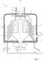
- Fig. 1 shows a cross-section of a centrifugal separator 1 according to the present disclosure.
- the centrifugal separator 1 comprises a stationary casing 2, which is configured to be mounted to a combustion engine (not disclosed), especially a diesel engine, at a suitable position, such as on top of the combustion engine or at the side of the combustion engine.
- centrifugal separator 1 is also suitable for cleaning gases from other sources than combustion engines, for instance the environment of machine tools which frequently contains large amounts of liquid contaminants in the form of oil droplets or oil mist.
- the stationary casing 2 encloses a separation space 3 through which a gas flow is permitted.
- the stationary casing 2 comprises, or is formed by, a surrounding side wall 4, an upper end wall 5 and a lower end wall 6
- the centrifugal separator comprises a rotating member 7, which is arranged to rotate around an axis (X) of rotation. It should be noted that the stationary casing 2 is stationary in relation to the rotating member 7, and preferably in relation to the combustion engine to which it may be mounted.
- the stationary casing 2 has a radius from the axis (X) of rotation to the surrounding side wall 4 that is constant at least with respect to a major part of the circumference of the surrounding side wall 4.
- the surrounding side wall 4 thus has a circular, or substantially, circular cross-section.
- the rotating member 7 comprises a rotatable shaft, i.e. spindle 8 and a stack of separation discs 9 attached to the spindle 8. All the separation discs of the stack 9 are provided between a top disc 10 and a lower end plate 11.
- the spindle 8, and thus the rotating member 7, is rotatably supported in the stationary casing 2 by means of an upper bearing 12 and a lower bearing 13, the bearings being arranged one on each axial side of the stack of separation discs 9.
- the upper bearing 12 is retained in upper bearing holder 30, which will be described in more detail in relation to Figs. 2 - 4 below.
- the centrifugal separator 1 is free of any spring member arranged for providing the preload to the upper bearing 12.
- the lower bearing 13 may be mounted in a stiff configuration or stiff bearing holder.
- the separation discs of the disc stack 9 are frusto-conical and extend outwardly and downwardly from the spindle 8.
- the separation discs thus comprise a flat portion 9a, which extend perpendicularly to the axis of rotation (X), and a conical portion 9b, that extend outwardly and downwardly from the flat portion 9a.
- separation discs also could extend outwardly and upwardly, or even radially.
- the separation discs of the stack 9 are provided at a distance from each other by means of distance members (not disclosed) in order to form interspaces 14 between adjacent separation discs 9, i.e. an interspace 14 between each pair of adjacent separation discs 9.
- the axial thickness of each interspace 14 may e.g. be in the order of 0.5 -2 mm, such as 1-2 mm.
- the separation discs of the stack 9 may be made of plastic or metal.
- the number of separation discs in the stack 9 is normally higher than indicated in Fig. 1 and may be for instance 50 to 100 separation discs 9 depending on the size of the centrifugal separator.
- the centrifugal separator 1 comprises an oil nozzle 24 arranged for being connected to an engine oil circuit of an internal combustion engine. During running of the internal combustion engine, oil is pumped through the oil nozzle 24 onto a wheel 22 connected to the spindle 8 to thereby rotate the rotating member 7 and thus the stack of separation discs 9.
- the centrifugal separator 1 may comprise an electric motor arranged to rotate the spindle 8 and rotating member 7.
- the centrifugal separator 3 may comprise a turbine wheel connected to the spindle 8, where the turbine wheel is arranged to be driven by exhaust gases from the internal combustion engine to rotate the spindle 8 and the rotating member 7.
- the rotating member 7 may also be arranged for being rotated by a mechanical drive unit.
- the centrifugal separator may comprise a mechanical drive unit for rotating the rotating member.
- the rotating member 7 defines a central space 15.
- the central space 15 is formed by a through hole in each of the separation discs 9.
- the central space 15 is formed by a plurality of through holes, each extending through the top disc 10 and through each of the separation discs 9, but not through the lower end plate 11.
- the through holes are arranged in the flat portions 9a of the separation discs.
- the gas inlet 20 is for the supply of the gas to be cleaned.
- the gas inlet 20 extends through the stationary casing 2, and more precisely through upper end wall 5.
- the gas inlet 20 is formed by the axially extending inlet conduit 18, which forms an upstream portion, and through channels 21 that form a downstream portion of the inlet 20.
- the through channels 21 are arranged radially outside the upper bearing 12, through which the inlet conduit 18 communicates with central space 15.
- the gas inlet 20 communicates with the central space 15 so that the gas to be cleaned is conveyed from the inlet 20 via the central space 15 to the interspaces 14 of the stack of separation discs 9.
- the gas inlet 20 is configured to communicate with the crankcase of the combustion engine, or any other source, via the inlet conduit 18 permitting the supply of crankcase gas from the crankcase to the gas inlet 20 and further to the central space 15 and the interspaces 14 as explained above.
- the centrifugal separator 1 comprises a drainage outlet 29 arranged in the lower portion of the stationary casing 2 and configured to permit discharge of liquid contaminants separated from the gas.
- the drainage outlet 29 is in this embodiment in the form of through holes arranged in the lower end wall 6 so that separated liquid contaminants flow through the lower bearing 13 as they are drained from the separation space 3.
- the separated oil, and other particles and/or substances, is led to an oil outlet 25 of the centrifugal separator 1, which together with oil from the oil nozzle 24 used to drive the wheel 22, may be led back to the engine oil circuit of an internal combustion engine.
- the gas outlet 28 of the centrifugal separator 1 is arranged in the lower portion of the stationary casing 2 and is configured to permit discharge of cleaned gas.
- the gas outlet 28 comprises an outlet conduit through the surrounding side wall 4 of the stationary casing 2.
- the gas outlet 28 is in this embodiment arranged in the lower portion of the surrounding side wall 4, but the gas outlet 28 could also be arranged in an upper portion of the stationary casing 2, such as in the upper end wall 5.
- the rotating member 7 is kept in rotation by the oil nozzle 24 supplying oil against the wheel 22.
- the rotational speed may be in the range of 7.500-12.000 rpm.
- Contaminated gas e.g. crankcase gas from the crankcase of an internal combustion engine
- Contaminated gas is supplied to the gas inlet 20 via conduit 18.
- This gas is conducted further into the central space 15 and from there into and through the interspaces 14 between the separation discs of the stack 9.
- the gas is brought to rotate, whereby it is pumped further on radially outwardly through gaps or interspaces 14.
- the inner wall of the bottom end wall may be tilted radially inwards, so that oil leaving the surrounding inner wall of the stationary casing 2 may be pulled by gravity towards drainage outlet 29.
- the path of the contaminants in the gas is schematically illustrated by arrows "D" in Fig. 1 .
- the bearings 12,13 are arranged on either sides of the stack of separation discs 9.
- both bearing could for example both be arranged axially below or above the stack of separation discs.
- Fig. 2 shows a close-up view of the upper bearing 12 retained in the upper bearing holder 30. It should be understood that the bearing holder 30 described in relation to Fig. 2 may as well be the arrangement of a bearing holder arranged for the lower bearing if the arrangement in the centrifugal separator 1 was different.
- the bearing holder 30 comprises a central portion 32 which supports the outer, stationary ring 40 of the bearing 12.
- the central portion 32 may be annular around the axis of rotation (X) and form a container into which the bearing 12 may be arranged.
- a plurality of radial spokes 33 extends radially outwards from the central portion 32.
- Th bearing holder is attached to a stationary portion of the centrifugal separator 1, such as to the stationary casing 2, via the radial spokes 33.
- the upper bearing holder 30 is attached via the spokes 33 to a lower portion of the stationary inlet pipe 18, which forms part of the upper end wall 5 of the stationary casing 2. Attachment of the spokes 33 to the stationary portion is performed using attachment members 35 in the form of screws.
- the upper bearing holder 30 is flexible in the axial direction when it is dismounted form the centrifugal separator.
- the upper bearing holder 30 When arranged in the centrifugal separator 1, the upper bearing holder 30 is mounted with a pre-tension to provide an axial preload to the upper bearing 12 in the centrifugal separator 1. This may thus be achieved by flexing the bearing holder 30 in the axial direction and mount the bearing holder to a stationary portion in a slightly flexed state.
- Fig. 3 shows a perspective view of a section of a bearing holder 30 and upper bearing 12 mounted in the centrifugal separator 1.
- the bearing holder 30 is attached to a stationary portion 18 of the centrifugal separator at a radially outer portion by means of screws 35.
- the bearing holder 30 comprises in this example eight radial spokes 33, which form through openings 39.
- the though openings 39 may form part of the through channels 21, through which the inlet conduit 18 communicates with central space 15.
- Due to the radial spokes 33 the bearing holder 30 is flexible in the axial direction when dismounted from the centrifugal separator 1, as illustrated by arrows 50 in Fig. 3 .
- the bearing holder 30 may be flexed so as to provide an axial upward force to the bearing 12.
- Fig. 4 shows a top view of an example of a bearing holder 30 when dismounted from the centrifugal separator 1.
- the bearing holder 30 comprises a central portion 32 arranged for supporting a bearing and in this example eight radial spokes 33 extending from the central portion 32.
- the radial spokes 33 are connected at a radially outer portion to form an annular ring structure 36 at the radially outer portion.
- the central portion 32 for holding the bearing is flexible in the axial direction due to a flexibility in the radial spokes 33.
- the axial direction is thus in the direction of the rotational axis of a bearing that is inserted in the central portion 32 of the bearing holder 30.
- the bearing holder 30 further comprises attachment means 37 at a radially outer portion of the radial spokes 33.
- the attachment means 37 are in the form of through holes arranged for receiving fastening means, such as a screw.
- Fig. 5 further shows an example in which both upper 12 and lower 13 bearing s are arranged in a lower portion of the centrifugal separator.
- both bearings 12, 13 are arranged axially below the separation space in a separate chamber 70 of the housing 2.
- both bearings 12, 13 are arranged at a lower portion of the spindle 8.
- the lower bearing 13 is arranged in a bearing holder of the present disclosure, whereas the upper bearing 12 is arranged in a stiff manner without pre-load.
- the bearing holder 30 for the lower bearing 13 comprises a central portion 32, but instead of any spokes, there is a radial disc element 60 extending radially outwards from the central portion.
- the bearing holder 30 is flexible in the axial direction when dismounted form the centrifugal separator. Further, the bearing holder 30 is attached to a portion of the housing 2 at radially outer positions, in this case via screw members 35 extending through attachment means, i.e. the through holes 37, of the radial disc element 60.
- centrifugal separator also comprises centrifugal separators with a substantially horizontally oriented axis of rotation.
Landscapes
- Engineering & Computer Science (AREA)
- General Engineering & Computer Science (AREA)
- Mechanical Engineering (AREA)
- Centrifugal Separators (AREA)
- Lubrication Details And Ventilation Of Internal Combustion Engines (AREA)
Claims (9)
- Zentrifugalabscheider (1) zum Reinigen von Gas enthaltenden Verunreinigungen, umfassendein feststehendes Gehäuse (2), das einen Abscheideraum (3) umschließt, durch den ein Gasstrom zugelassen wird,einen Gaseinlass (20), der sich durch das feststehende Gehäuse (2) erstreckt und eine Zufuhr des zu reinigenden Gases zulässt,ein sich drehendes Element (7), umfassend eine Vielzahl von Abscheideelementen (9), die in dem Abscheideraum (3) angeordnet sind und derart angeordnet sind, dass sie sich um eine Rotationsachse (X) drehen, wobei das sich drehende Element (7) innerhalb des feststehenden Gehäuses (2) über mindestens ein Lager (12), das in einer Lagerhalterung (30) zurückgehalten wird, gelagert ist,einen Gasauslass (28), der in dem feststehenden Gehäuse (2) angeordnet und dafür konfiguriert ist, eine Abgabe von gereinigtem Gas zuzulassen, und eine Auslassöffnung durch eine Wand des feststehenden Gehäuses (2) umfasst,einen Drainageauslass (29), der in dem feststehenden Gehäuse (2) angeordnet und dafür konfiguriert ist, eine Abgabe von flüssigen Verunreinigungen zuzulassen, die von dem zu reinigenden Gas abgeschieden werden;ein Antriebselement (22) zum Drehen des sich drehenden Elements (7);wobei das mindestens eine Lager (12) mit einer axialen Vorlast in dem Zentrifugalabscheider (1) montiert ist, unddadurch gekennzeichnet, dass die mindestens eine Lagerhalterung (30) flexibel ist, wenn sie von dem Zentrifugalabscheider (1) abmontiert wird, und in dem Zentrifugalabscheider (1) mit einer Vorspannung angeordnet ist, um die axiale Vorlast des mindestens einen Lagers (12) bereitzustellen,wobei die Lagerhalterung (30) einen mittleren Abschnitt (32), der das Lager (12) trägt, und mindestens zwei radiale Speichen (33) umfasst, die sich von dem mittleren Abschnitt (32) erstrecken, undwobei eine zwischen den radialen Speichen (33) gebildete Durchgangsöffnung (39) einen Teil des Gaseinlasses oder des Drainageauslasses bildet.
- Zentrifugalabscheider (1) nach Anspruch 1, wobei der Zentrifugalabscheider (1) frei von jeglichem Druckfederelement ist, das angeordnet ist, um die Vorlast des mindestens einen Lagers (12) bereitzustellen.
- Zentrifugalabscheider (1) nach Anspruch 1 oder 2, wobei das mindestens eine Lager (12) ein oberes und/oder ein unteres Lager umfasst, das axial auf jeder Seite der Abscheideelemente (9) angeordnet ist.
- Zentrifugalabscheider (1) nach einem der vorhergehenden Ansprüche, wobei das sich drehende Element (7) eine Axialwelle (8) umfasst, die von dem mindestens einen Lager (12) getragen wird.
- Zentrifugalabscheider (1) nach einem der vorhergehenden Ansprüche, wobei das mindestens eine Lager (12) einen drehbaren Innenring (42) und einen feststehenden Außenring (40) umfasst, und wobei die Lagerhalterung (30) den Außenring (40) des Lagers (12) trägt.
- Zentrifugalabscheider (1) nach einem der vorhergehenden Ansprüche, wobei die Lagerhalterung (30) an einem feststehenden Abschnitt (18) des Zentrifugalabscheiders (1) an einem radial äußeren Abschnitt der Lagerhalterung (30) angebracht ist.
- Zentrifugalabscheider (1) nach einem der vorhergehenden Ansprüche, wobei die Lagerhalterung (30) an einem feststehenden Abschnitt (18) des Zentrifugalabscheiders (1) an den radial äußeren Abschnitten der mindestens zwei radialen Speichen (33) angebracht ist.
- Zentrifugalabscheider (1) nach Anspruch 7, wobei die mindestens zwei Speichen (33) mit einem radial äußeren Abschnitt verbunden sind, um eine Ringstruktur (36) an dem radial äußeren Abschnitt zu bilden.
- Zentrifugalabscheider (1) nach einem der vorhergehenden Ansprüche, wobei es sich bei der Vielzahl von Abscheideelementen (9) um einen Stapel von Abscheideplatten handelt.
Priority Applications (4)
| Application Number | Priority Date | Filing Date | Title |
|---|---|---|---|
| EP21169189.4A EP4079407B1 (de) | 2021-04-19 | 2021-04-19 | Zentrifugalabscheider mit einem lagerhalter |
| PCT/EP2022/057519 WO2022223221A1 (en) | 2021-04-19 | 2022-03-22 | A centrifugal separator comprising a bearing holder |
| CN202280043367.4A CN117500605A (zh) | 2021-04-19 | 2022-03-22 | 包括轴承保持件的离心分离器 |
| US18/287,413 US20240198361A1 (en) | 2021-04-19 | 2022-03-22 | A centrifugal separator comprising a bearing holder |
Applications Claiming Priority (1)
| Application Number | Priority Date | Filing Date | Title |
|---|---|---|---|
| EP21169189.4A EP4079407B1 (de) | 2021-04-19 | 2021-04-19 | Zentrifugalabscheider mit einem lagerhalter |
Publications (2)
| Publication Number | Publication Date |
|---|---|
| EP4079407A1 EP4079407A1 (de) | 2022-10-26 |
| EP4079407B1 true EP4079407B1 (de) | 2024-11-20 |
Family
ID=75588046
Family Applications (1)
| Application Number | Title | Priority Date | Filing Date |
|---|---|---|---|
| EP21169189.4A Active EP4079407B1 (de) | 2021-04-19 | 2021-04-19 | Zentrifugalabscheider mit einem lagerhalter |
Country Status (4)
| Country | Link |
|---|---|
| US (1) | US20240198361A1 (de) |
| EP (1) | EP4079407B1 (de) |
| CN (1) | CN117500605A (de) |
| WO (1) | WO2022223221A1 (de) |
Family Cites Families (3)
| Publication number | Priority date | Publication date | Assignee | Title |
|---|---|---|---|---|
| CH250450A (de) * | 1945-04-27 | 1947-08-31 | Skf Svenska Kullagerfab Ab | Wälzlagereinrichtung. |
| US5364194A (en) * | 1993-01-04 | 1994-11-15 | Ampex Systems Corporation | Axially displaced flexural bearing support |
| US8657908B2 (en) | 2009-07-10 | 2014-02-25 | Alfa Laval Corporate Ab | Gas cleaning separator |
-
2021
- 2021-04-19 EP EP21169189.4A patent/EP4079407B1/de active Active
-
2022
- 2022-03-22 US US18/287,413 patent/US20240198361A1/en active Pending
- 2022-03-22 WO PCT/EP2022/057519 patent/WO2022223221A1/en not_active Ceased
- 2022-03-22 CN CN202280043367.4A patent/CN117500605A/zh active Pending
Also Published As
| Publication number | Publication date |
|---|---|
| CN117500605A (zh) | 2024-02-02 |
| EP4079407A1 (de) | 2022-10-26 |
| US20240198361A1 (en) | 2024-06-20 |
| WO2022223221A1 (en) | 2022-10-27 |
Similar Documents
| Publication | Publication Date | Title |
|---|---|---|
| CA2972837C (en) | Centrifugal separator for cleaning gas | |
| EP4079408B1 (de) | Zentrifugalseparator zur reinigung von gas | |
| WO2024052112A1 (en) | A centrifugal separator for cleaning gas | |
| US12594561B2 (en) | Modular centrifugal separator for cleaning gas | |
| EP4079407B1 (de) | Zentrifugalabscheider mit einem lagerhalter | |
| EP4292715B1 (de) | Zentrifugalseparator für reinigungsgas | |
| US20250214090A1 (en) | A centrifugal separator comprising a turbine casing | |
| EP4616925A1 (de) | Zentrifugalabscheider zur gasreinigung | |
| EP4005679B1 (de) | Zentrifugalabscheider zum reinigen von gas | |
| US20260117685A1 (en) | Centrifugal separator for cleaning gas | |
| EP4523794A1 (de) | Zentrifugalabscheider zum reinigen von gas | |
| EP4385626A1 (de) | Zentrifugalabscheider zum reinigen von gas |
Legal Events
| Date | Code | Title | Description |
|---|---|---|---|
| PUAI | Public reference made under article 153(3) epc to a published international application that has entered the european phase |
Free format text: ORIGINAL CODE: 0009012 |
|
| STAA | Information on the status of an ep patent application or granted ep patent |
Free format text: STATUS: THE APPLICATION HAS BEEN PUBLISHED |
|
| AK | Designated contracting states |
Kind code of ref document: A1 Designated state(s): AL AT BE BG CH CY CZ DE DK EE ES FI FR GB GR HR HU IE IS IT LI LT LU LV MC MK MT NL NO PL PT RO RS SE SI SK SM TR |
|
| STAA | Information on the status of an ep patent application or granted ep patent |
Free format text: STATUS: REQUEST FOR EXAMINATION WAS MADE |
|
| 17P | Request for examination filed |
Effective date: 20230322 |
|
| RBV | Designated contracting states (corrected) |
Designated state(s): AL AT BE BG CH CY CZ DE DK EE ES FI FR GB GR HR HU IE IS IT LI LT LU LV MC MK MT NL NO PL PT RO RS SE SI SK SM TR |
|
| STAA | Information on the status of an ep patent application or granted ep patent |
Free format text: STATUS: EXAMINATION IS IN PROGRESS |
|
| 17Q | First examination report despatched |
Effective date: 20240411 |
|
| REG | Reference to a national code |
Ref country code: DE Ref legal event code: R079 Ref document number: 602021021970 Country of ref document: DE Free format text: PREVIOUS MAIN CLASS: B04B0005120000 Ipc: F16C0019060000 |
|
| GRAP | Despatch of communication of intention to grant a patent |
Free format text: ORIGINAL CODE: EPIDOSNIGR1 |
|
| STAA | Information on the status of an ep patent application or granted ep patent |
Free format text: STATUS: GRANT OF PATENT IS INTENDED |
|
| RIC1 | Information provided on ipc code assigned before grant |
Ipc: F16C 35/04 20060101ALI20240704BHEP Ipc: F16C 25/08 20060101ALI20240704BHEP Ipc: F01M 13/04 20060101ALI20240704BHEP Ipc: B04B 9/12 20060101ALI20240704BHEP Ipc: B04B 5/12 20060101ALI20240704BHEP Ipc: F16C 19/06 20060101AFI20240704BHEP |
|
| INTG | Intention to grant announced |
Effective date: 20240723 |
|
| GRAS | Grant fee paid |
Free format text: ORIGINAL CODE: EPIDOSNIGR3 |
|
| GRAA | (expected) grant |
Free format text: ORIGINAL CODE: 0009210 |
|
| STAA | Information on the status of an ep patent application or granted ep patent |
Free format text: STATUS: THE PATENT HAS BEEN GRANTED |
|
| P01 | Opt-out of the competence of the unified patent court (upc) registered |
Free format text: CASE NUMBER: APP_52507/2024 Effective date: 20240920 |
|
| AK | Designated contracting states |
Kind code of ref document: B1 Designated state(s): AL AT BE BG CH CY CZ DE DK EE ES FI FR GB GR HR HU IE IS IT LI LT LU LV MC MK MT NL NO PL PT RO RS SE SI SK SM TR |
|
| REG | Reference to a national code |
Ref country code: GB Ref legal event code: FG4D |
|
| REG | Reference to a national code |
Ref country code: CH Ref legal event code: EP |
|
| REG | Reference to a national code |
Ref country code: DE Ref legal event code: R096 Ref document number: 602021021970 Country of ref document: DE |
|
| REG | Reference to a national code |
Ref country code: IE Ref legal event code: FG4D |
|
| REG | Reference to a national code |
Ref country code: SE Ref legal event code: TRGR |
|
| REG | Reference to a national code |
Ref country code: LT Ref legal event code: MG9D |
|
| REG | Reference to a national code |
Ref country code: NL Ref legal event code: MP Effective date: 20241120 |
|
| PG25 | Lapsed in a contracting state [announced via postgrant information from national office to epo] |
Ref country code: IS Free format text: LAPSE BECAUSE OF FAILURE TO SUBMIT A TRANSLATION OF THE DESCRIPTION OR TO PAY THE FEE WITHIN THE PRESCRIBED TIME-LIMIT Effective date: 20250320 Ref country code: PT Free format text: LAPSE BECAUSE OF FAILURE TO SUBMIT A TRANSLATION OF THE DESCRIPTION OR TO PAY THE FEE WITHIN THE PRESCRIBED TIME-LIMIT Effective date: 20250320 Ref country code: HR Free format text: LAPSE BECAUSE OF FAILURE TO SUBMIT A TRANSLATION OF THE DESCRIPTION OR TO PAY THE FEE WITHIN THE PRESCRIBED TIME-LIMIT Effective date: 20241120 |
|
| PG25 | Lapsed in a contracting state [announced via postgrant information from national office to epo] |
Ref country code: FI Free format text: LAPSE BECAUSE OF FAILURE TO SUBMIT A TRANSLATION OF THE DESCRIPTION OR TO PAY THE FEE WITHIN THE PRESCRIBED TIME-LIMIT Effective date: 20241120 Ref country code: NL Free format text: LAPSE BECAUSE OF FAILURE TO SUBMIT A TRANSLATION OF THE DESCRIPTION OR TO PAY THE FEE WITHIN THE PRESCRIBED TIME-LIMIT Effective date: 20241120 |
|
| REG | Reference to a national code |
Ref country code: AT Ref legal event code: MK05 Ref document number: 1743825 Country of ref document: AT Kind code of ref document: T Effective date: 20241120 |
|
| PG25 | Lapsed in a contracting state [announced via postgrant information from national office to epo] |
Ref country code: BG Free format text: LAPSE BECAUSE OF FAILURE TO SUBMIT A TRANSLATION OF THE DESCRIPTION OR TO PAY THE FEE WITHIN THE PRESCRIBED TIME-LIMIT Effective date: 20241120 |
|
| PG25 | Lapsed in a contracting state [announced via postgrant information from national office to epo] |
Ref country code: ES Free format text: LAPSE BECAUSE OF FAILURE TO SUBMIT A TRANSLATION OF THE DESCRIPTION OR TO PAY THE FEE WITHIN THE PRESCRIBED TIME-LIMIT Effective date: 20241120 |
|
| PG25 | Lapsed in a contracting state [announced via postgrant information from national office to epo] |
Ref country code: NO Free format text: LAPSE BECAUSE OF FAILURE TO SUBMIT A TRANSLATION OF THE DESCRIPTION OR TO PAY THE FEE WITHIN THE PRESCRIBED TIME-LIMIT Effective date: 20250220 |
|
| PG25 | Lapsed in a contracting state [announced via postgrant information from national office to epo] |
Ref country code: AT Free format text: LAPSE BECAUSE OF FAILURE TO SUBMIT A TRANSLATION OF THE DESCRIPTION OR TO PAY THE FEE WITHIN THE PRESCRIBED TIME-LIMIT Effective date: 20241120 Ref country code: GR Free format text: LAPSE BECAUSE OF FAILURE TO SUBMIT A TRANSLATION OF THE DESCRIPTION OR TO PAY THE FEE WITHIN THE PRESCRIBED TIME-LIMIT Effective date: 20250221 Ref country code: LV Free format text: LAPSE BECAUSE OF FAILURE TO SUBMIT A TRANSLATION OF THE DESCRIPTION OR TO PAY THE FEE WITHIN THE PRESCRIBED TIME-LIMIT Effective date: 20241120 |
|
| PG25 | Lapsed in a contracting state [announced via postgrant information from national office to epo] |
Ref country code: PL Free format text: LAPSE BECAUSE OF FAILURE TO SUBMIT A TRANSLATION OF THE DESCRIPTION OR TO PAY THE FEE WITHIN THE PRESCRIBED TIME-LIMIT Effective date: 20241120 |
|
| PG25 | Lapsed in a contracting state [announced via postgrant information from national office to epo] |
Ref country code: RS Free format text: LAPSE BECAUSE OF FAILURE TO SUBMIT A TRANSLATION OF THE DESCRIPTION OR TO PAY THE FEE WITHIN THE PRESCRIBED TIME-LIMIT Effective date: 20250220 |
|
| PG25 | Lapsed in a contracting state [announced via postgrant information from national office to epo] |
Ref country code: SM Free format text: LAPSE BECAUSE OF FAILURE TO SUBMIT A TRANSLATION OF THE DESCRIPTION OR TO PAY THE FEE WITHIN THE PRESCRIBED TIME-LIMIT Effective date: 20241120 |
|
| PGFP | Annual fee paid to national office [announced via postgrant information from national office to epo] |
Ref country code: DE Payment date: 20250305 Year of fee payment: 5 |
|
| PG25 | Lapsed in a contracting state [announced via postgrant information from national office to epo] |
Ref country code: DK Free format text: LAPSE BECAUSE OF FAILURE TO SUBMIT A TRANSLATION OF THE DESCRIPTION OR TO PAY THE FEE WITHIN THE PRESCRIBED TIME-LIMIT Effective date: 20241120 |
|
| PG25 | Lapsed in a contracting state [announced via postgrant information from national office to epo] |
Ref country code: EE Free format text: LAPSE BECAUSE OF FAILURE TO SUBMIT A TRANSLATION OF THE DESCRIPTION OR TO PAY THE FEE WITHIN THE PRESCRIBED TIME-LIMIT Effective date: 20241120 |
|
| PG25 | Lapsed in a contracting state [announced via postgrant information from national office to epo] |
Ref country code: RO Free format text: LAPSE BECAUSE OF FAILURE TO SUBMIT A TRANSLATION OF THE DESCRIPTION OR TO PAY THE FEE WITHIN THE PRESCRIBED TIME-LIMIT Effective date: 20241120 |
|
| PG25 | Lapsed in a contracting state [announced via postgrant information from national office to epo] |
Ref country code: SK Free format text: LAPSE BECAUSE OF FAILURE TO SUBMIT A TRANSLATION OF THE DESCRIPTION OR TO PAY THE FEE WITHIN THE PRESCRIBED TIME-LIMIT Effective date: 20241120 |
|
| PG25 | Lapsed in a contracting state [announced via postgrant information from national office to epo] |
Ref country code: CZ Free format text: LAPSE BECAUSE OF FAILURE TO SUBMIT A TRANSLATION OF THE DESCRIPTION OR TO PAY THE FEE WITHIN THE PRESCRIBED TIME-LIMIT Effective date: 20241120 |
|
| REG | Reference to a national code |
Ref country code: DE Ref legal event code: R097 Ref document number: 602021021970 Country of ref document: DE |
|
| PLBE | No opposition filed within time limit |
Free format text: ORIGINAL CODE: 0009261 |
|
| STAA | Information on the status of an ep patent application or granted ep patent |
Free format text: STATUS: NO OPPOSITION FILED WITHIN TIME LIMIT |
|
| 26N | No opposition filed |
Effective date: 20250821 |
|
| REG | Reference to a national code |
Ref country code: CH Ref legal event code: H13 Free format text: ST27 STATUS EVENT CODE: U-0-0-H10-H13 (AS PROVIDED BY THE NATIONAL OFFICE) Effective date: 20251125 |
|
| PG25 | Lapsed in a contracting state [announced via postgrant information from national office to epo] |
Ref country code: LU Free format text: LAPSE BECAUSE OF NON-PAYMENT OF DUE FEES Effective date: 20250419 |
|
| PG25 | Lapsed in a contracting state [announced via postgrant information from national office to epo] |
Ref country code: MC Free format text: LAPSE BECAUSE OF FAILURE TO SUBMIT A TRANSLATION OF THE DESCRIPTION OR TO PAY THE FEE WITHIN THE PRESCRIBED TIME-LIMIT Effective date: 20241120 |
|
| REG | Reference to a national code |
Ref country code: BE Ref legal event code: MM Effective date: 20250430 |
|
| PG25 | Lapsed in a contracting state [announced via postgrant information from national office to epo] |
Ref country code: FR Free format text: LAPSE BECAUSE OF NON-PAYMENT OF DUE FEES Effective date: 20250430 |
|
| PG25 | Lapsed in a contracting state [announced via postgrant information from national office to epo] |
Ref country code: BE Free format text: LAPSE BECAUSE OF NON-PAYMENT OF DUE FEES Effective date: 20250430 |
|
| PG25 | Lapsed in a contracting state [announced via postgrant information from national office to epo] |
Ref country code: CH Free format text: LAPSE BECAUSE OF NON-PAYMENT OF DUE FEES Effective date: 20250430 |
|
| PGFP | Annual fee paid to national office [announced via postgrant information from national office to epo] |
Ref country code: SE Payment date: 20260312 Year of fee payment: 6 |
|
| PGFP | Annual fee paid to national office [announced via postgrant information from national office to epo] |
Ref country code: GB Payment date: 20260303 Year of fee payment: 6 |
|
| PG25 | Lapsed in a contracting state [announced via postgrant information from national office to epo] |
Ref country code: IE Free format text: LAPSE BECAUSE OF NON-PAYMENT OF DUE FEES Effective date: 20250419 |
|
| PGFP | Annual fee paid to national office [announced via postgrant information from national office to epo] |
Ref country code: IT Payment date: 20260320 Year of fee payment: 6 |