EP4079355B1 - Total liquid ventilation system and method - Google Patents
Total liquid ventilation system and method Download PDFInfo
- Publication number
- EP4079355B1 EP4079355B1 EP21305533.8A EP21305533A EP4079355B1 EP 4079355 B1 EP4079355 B1 EP 4079355B1 EP 21305533 A EP21305533 A EP 21305533A EP 4079355 B1 EP4079355 B1 EP 4079355B1
- Authority
- EP
- European Patent Office
- Prior art keywords
- bag
- fluid
- gas
- breathable liquid
- liquid
- Prior art date
- Legal status (The legal status is an assumption and is not a legal conclusion. Google has not performed a legal analysis and makes no representation as to the accuracy of the status listed.)
- Active
Links
Images


Classifications
-
- A—HUMAN NECESSITIES
- A61—MEDICAL OR VETERINARY SCIENCE; HYGIENE
- A61M—DEVICES FOR INTRODUCING MEDIA INTO, OR ONTO, THE BODY; DEVICES FOR TRANSDUCING BODY MEDIA OR FOR TAKING MEDIA FROM THE BODY; DEVICES FOR PRODUCING OR ENDING SLEEP OR STUPOR
- A61M16/00—Devices for influencing the respiratory system of patients by gas treatment, e.g. ventilators; Tracheal tubes
- A61M16/0054—Liquid ventilation
-
- A—HUMAN NECESSITIES
- A61—MEDICAL OR VETERINARY SCIENCE; HYGIENE
- A61F—FILTERS IMPLANTABLE INTO BLOOD VESSELS; PROSTHESES; DEVICES PROVIDING PATENCY TO, OR PREVENTING COLLAPSING OF, TUBULAR STRUCTURES OF THE BODY, e.g. STENTS; ORTHOPAEDIC, NURSING OR CONTRACEPTIVE DEVICES; FOMENTATION; TREATMENT OR PROTECTION OF EYES OR EARS; BANDAGES, DRESSINGS OR ABSORBENT PADS; FIRST-AID KITS
- A61F7/00—Heating or cooling appliances for medical or therapeutic treatment of the human body
- A61F7/0085—Devices for generating hot or cold treatment fluids
-
- A—HUMAN NECESSITIES
- A61—MEDICAL OR VETERINARY SCIENCE; HYGIENE
- A61M—DEVICES FOR INTRODUCING MEDIA INTO, OR ONTO, THE BODY; DEVICES FOR TRANSDUCING BODY MEDIA OR FOR TAKING MEDIA FROM THE BODY; DEVICES FOR PRODUCING OR ENDING SLEEP OR STUPOR
- A61M16/00—Devices for influencing the respiratory system of patients by gas treatment, e.g. ventilators; Tracheal tubes
- A61M16/021—Devices for influencing the respiratory system of patients by gas treatment, e.g. ventilators; Tracheal tubes operated by electrical means
- A61M16/022—Control means therefor
-
- A—HUMAN NECESSITIES
- A61—MEDICAL OR VETERINARY SCIENCE; HYGIENE
- A61M—DEVICES FOR INTRODUCING MEDIA INTO, OR ONTO, THE BODY; DEVICES FOR TRANSDUCING BODY MEDIA OR FOR TAKING MEDIA FROM THE BODY; DEVICES FOR PRODUCING OR ENDING SLEEP OR STUPOR
- A61M16/00—Devices for influencing the respiratory system of patients by gas treatment, e.g. ventilators; Tracheal tubes
- A61M16/04—Tracheal tubes
-
- A—HUMAN NECESSITIES
- A61—MEDICAL OR VETERINARY SCIENCE; HYGIENE
- A61F—FILTERS IMPLANTABLE INTO BLOOD VESSELS; PROSTHESES; DEVICES PROVIDING PATENCY TO, OR PREVENTING COLLAPSING OF, TUBULAR STRUCTURES OF THE BODY, e.g. STENTS; ORTHOPAEDIC, NURSING OR CONTRACEPTIVE DEVICES; FOMENTATION; TREATMENT OR PROTECTION OF EYES OR EARS; BANDAGES, DRESSINGS OR ABSORBENT PADS; FIRST-AID KITS
- A61F7/00—Heating or cooling appliances for medical or therapeutic treatment of the human body
- A61F2007/0059—Heating or cooling appliances for medical or therapeutic treatment of the human body with an open fluid circuit
-
- A—HUMAN NECESSITIES
- A61—MEDICAL OR VETERINARY SCIENCE; HYGIENE
- A61F—FILTERS IMPLANTABLE INTO BLOOD VESSELS; PROSTHESES; DEVICES PROVIDING PATENCY TO, OR PREVENTING COLLAPSING OF, TUBULAR STRUCTURES OF THE BODY, e.g. STENTS; ORTHOPAEDIC, NURSING OR CONTRACEPTIVE DEVICES; FOMENTATION; TREATMENT OR PROTECTION OF EYES OR EARS; BANDAGES, DRESSINGS OR ABSORBENT PADS; FIRST-AID KITS
- A61F7/00—Heating or cooling appliances for medical or therapeutic treatment of the human body
- A61F2007/0059—Heating or cooling appliances for medical or therapeutic treatment of the human body with an open fluid circuit
- A61F2007/0069—Heating or cooling appliances for medical or therapeutic treatment of the human body with an open fluid circuit with return means
-
- A—HUMAN NECESSITIES
- A61—MEDICAL OR VETERINARY SCIENCE; HYGIENE
- A61F—FILTERS IMPLANTABLE INTO BLOOD VESSELS; PROSTHESES; DEVICES PROVIDING PATENCY TO, OR PREVENTING COLLAPSING OF, TUBULAR STRUCTURES OF THE BODY, e.g. STENTS; ORTHOPAEDIC, NURSING OR CONTRACEPTIVE DEVICES; FOMENTATION; TREATMENT OR PROTECTION OF EYES OR EARS; BANDAGES, DRESSINGS OR ABSORBENT PADS; FIRST-AID KITS
- A61F7/00—Heating or cooling appliances for medical or therapeutic treatment of the human body
- A61F7/12—Devices for heating or cooling internal body cavities
-
- A—HUMAN NECESSITIES
- A61—MEDICAL OR VETERINARY SCIENCE; HYGIENE
- A61M—DEVICES FOR INTRODUCING MEDIA INTO, OR ONTO, THE BODY; DEVICES FOR TRANSDUCING BODY MEDIA OR FOR TAKING MEDIA FROM THE BODY; DEVICES FOR PRODUCING OR ENDING SLEEP OR STUPOR
- A61M2202/00—Special media to be introduced, removed or treated
- A61M2202/04—Liquids
- A61M2202/0468—Liquids non-physiological
- A61M2202/0476—Oxygenated solutions
-
- A—HUMAN NECESSITIES
- A61—MEDICAL OR VETERINARY SCIENCE; HYGIENE
- A61M—DEVICES FOR INTRODUCING MEDIA INTO, OR ONTO, THE BODY; DEVICES FOR TRANSDUCING BODY MEDIA OR FOR TAKING MEDIA FROM THE BODY; DEVICES FOR PRODUCING OR ENDING SLEEP OR STUPOR
- A61M2205/00—General characteristics of the apparatus
- A61M2205/36—General characteristics of the apparatus related to heating or cooling
- A61M2205/3606—General characteristics of the apparatus related to heating or cooling cooled
Definitions
- Mechanical ventilators are machine used to support the ventilatory function of critically ill patients, to replace the function of the lungs until the patient's spontaneous ventilation can be restored.
- Mechanical ventilators may be used to replace the lung function for a limited amount of time, but they face limitations due to their pro-inflammatory effect in some situations of respiratory distresses such as the ones induced by COVID and other infectious agents. Moreover, mechanical ventilators may cause lung damage, such as ventilator-induced lung injury (VILI).
- VILI ventilator-induced lung injury
- Total Liquid Ventilation (TLV) strategies hold the promise of a radical shift in ventilation.
- TLV Total Liquid Ventilation
- the mammal is ventilated with a breathable liquid having a high solubility for oxygen and carbon dioxide, such as perfluorocarbons, rather than with an oxygen-containing gas mixture.
- TLV allows to use the lungs as heat exchangers with the blood pool.
- Total liquid ventilators traditionally comprise an oxygenator configured to remove carbon dioxide, and introduce dioxygen, in the breathable liquid.
- the breathable liquid may be cooled or heated simultaneously, or before, or after passing through the oxygenator.
- the renewed breathable liquid enriched in oxygen and brought at the desired temperature, can be reintroduced into the lungs of the subject via the endotracheal tube and an inspiratory pump and then extracted from the lungs through the endotracheal tube and an expiratory pump.
- the breathable liquid which exchange heat and gas with the blood compartment of the subj ect.
- Ice or cold-water baths, evaporators, or propane refrigerators may be used as cooling unit to cool a thermal fluid using metal-based heat transfer systems to exchange the heat between the breathable liquid and the thermal fluid cooled cooling unit and bring the breathable liquid at the desired temperature.
- metal-based heat transfer systems are not compatible with the requirements of a medical device for regular use in the clinical setting.
- the temperature regulation is not precise and bears the risk of under or over cooling the patient.
- these metal-based solutions are not compatible with a secure sterile approach to the treatment, i.e. they cannot guarantee that the breathable liquid that will be in contact with the lungs of the patient will not be contaminated by residues of a previous patient sticking to the walls of the metal heat exchangers.
- Another disadvantage of these systems is that the heat transfer with the breathable liquid is slow and inefficient.
- the present invention aims at providing a solution to the problems that are currently limiting the use of total liquid ventilators.
- an objective of the present invention is to provide a total liquid ventilator in which the heat exchange and gas exchange with the breathable liquid is optimized.
- the present disclosure relates to a total liquid ventilation system configured to deliver a breathable liquid to the lungs of a mammal, the total liquid ventilation system comprising an inspiratory circuit, an expiratory circuit, and a breathable liquid treatment unit.
- the breathable liquid treatment unit comprises:
- the system is compatible with the requirements of a medical device for regular use in the clinical setting. Indeed, it ensures a secure and sterile approach. Moreover, the temperature can be controlled precisely.
- the heat exchange system allows to provide a heat exchange and gas exchange with the breathable liquid, simultaneously.
- the system further comprises a recirculating circuit configured to connect the fluid outlet and the fluid inlet so as to define a closed circuit with the fluid duct; and the pump of the pumping system is for circulating the breathable liquid in the recirculating circuit.
- the circulation of the breathable liquid inside the closed circuit formed by the fluid duct and the recirculating circuit allows to provide several successive treatments (for instance: carbon dioxide removal, oxygen addition, heat exchange or a combination thereof) to the breathable liquid, before introducing the breathable liquid in the inspiratory circuit.
- the number of treatments per minute depends on the flow rate at which the breathable liquid is pumped by the pump of the pumping system.
- the bag further comprises a gas outlet and a pressure control valve mounted on said gas outlet.
- the gas outlet allows to remove CO 2 from the breathable liquid, before introducing the breathable liquid in the inspiratory circuit. Therefore, the inspiratory pump can pump in the endotracheal tube configured to be inserted in the mammal's trachea a breathable liquid with a low amount of CO 2 .
- the fluid duct may communicate with a reservoir configured to separate a gas from the breathable liquid, and the gas outlet may be located in proximity of said reservoir.
- a capnometer may be installed at the gas outlet 133, so as to measure the concentration of CO2 in the evacuated gas.
- the bag comprises a sealed boundary, and wherein the fluid duct is defined by the non-sealed portion of the bag surrounded by said sealed boundary.
- a pattern (the sealed boundary) is defined on the bag. More precisely, an inflatable compartment is defined within the non-sealed portion of the bag which is delimited by the sealed boundary. This inflatable compartment provides a fluid duct which can receive the breathable liquid.
- the fluid duct thus obtained has an improved tightness, because it is delimited by a sealed boundary. The leaking of the breathable liquid out of the fluid duct is thus avoided.
- the at least one plate and/or the backing device comprises a relief pattern or a recess pattern.
- the pattern on the plate at a controlled temperature and/or on the backing device may be in combination, or in alternative, to the pattern on the bag described hereabove.
- the bag may comprise a sealed boundary
- the plate and/or on the backing device may comprise a relief pattern complementary to the sealed boundary on the bag.
- the bag does not comprise a sealed boundary and the fluid duct is defined inside the portion of the bag which is sandwiched between by the patterns on the plate and/or on the backing device.
- the backing device is a plate parallel to the at least one plate, and separated from said at least one plate by a distance comprised between 0 mm and 20 mm, preferably between 4 mm and 15 mm.
- This distance allows to provide enough space for the bag and the fluid duct.
- the fluid duct comprises a serpentine duct extending between the fluid inlet and the fluid outlet and a fluid reservoir for separating a gas from the breathable liquid, said reservoir being fluidly connected with the serpentine duct and with the gas outlet of the bag.
- the fluid duct has a length which is longer more than twice the distance between the fluid inlet and the fluid outlet.
- This fluid duct communicates with a reservoir configured to separate a gas from the breathable liquid, and the gas outlet allows to expel the separated gas.
- the fluid reservoir has a volume comprised between 0.1 land 11.
- This embodiment ensures the presence of a volume large enough to contain the separated gas, before it is expelled through the gas outlet.
- system further comprises a second reservoir for buffering a breathable liquid from an expiratory pump.
- the second reservoir allows to obtain a constant flow rate of the breathable liquid inside the fluid duct and in the gas exchange system, thereby improving the heat and gas exchange occurring in said fluid duct.
- the second reservoir prevents an overload of the expiratory pump.
- a fluid port allows to introduce the breathable liquid inside the second reservoir before reaching the fluid duct.
- system further comprises a third reservoir for buffering a breathable liquid to be delivered to an inspiratory pump.
- the third reservoir advantageously allows to obtain a TLV system of compact dimensions, because the presence of buffer bags external to the heat exchange system is not required. More precisely, it is also possible to reduce the volume of breathable liquid circulating liquid inside the TLV system, and to provide a shorter inspiratory circuit.
- the thermal losses are minimized because the breathable liquid which has been treated in the breathable liquid treatment unit can reach more rapidly the inspiratory pump.
- the second reservoir and/or the third reservoir is integrated inside the bag.
- an all-in-one bag ensures that the breathable liquid is maintained at the same pressure during the breathable liquid treatment.
- the gas injection system comprises a gas mixing chamber fluidly connected to the fluid inlet of the bag.
- the gas mixing chamber allows to create homogeneous gas mixtures.
- the gas mixing chamber comprises a nozzle configured to generate micro-bubbles.
- This embodiment allows to obtain a two-phase mixture comprising the breathable liquid and the micro-bubbles.
- the bag is made of a plastic material selected from a group comprising: Thermoplastic polyurethane (TPU), Ethylene vinyl acetate (EVA), Polyvinyl Chloride (PVC).
- TPU Thermoplastic polyurethane
- EVA Ethylene vinyl acetate
- PVC Polyvinyl Chloride
- these materials are resistant to heat and pressure. Moreover, they have a low thermal resistance.
- the volume of the disposable bag is comprised between 1 l and 7 l.
- This volume ensure that enough breathable liquid can be contained inside the bag; more precisely, inside the fluid duct.
- the bag may be a disposable bag.
- a disposable bag allows to minimize the manual operations, thereby reducing the risk of contaminations.
- the present invention also relates to a method for providing thermal and gas exchange to a breathable liquid in a total liquid ventilation system according to any one of the embodiments described hereinabove, the method comprising:
- this method allows to provide simultaneous heat and gas exchange to the breathable liquid. Indeed, it allows to introduce a gas mixture in a breathable liquid withdrawn by the expiratory pump so as to obtain a two-phase mixture. Once inside the fluid duct, the two-phase mixture can exchange heat with the plate at controlled temperature.
- the step of introducing a gas mixture into the breathing liquid comprises:
- this embodiment allows to oxygenate a breathable liquid withdrawn by the expiratory pump, by introducing a gas mixture comprising oxygen.
- this embodiment allows to circulate the breathable liquid inside a closed circuit comprising the fluid duct and the recirculating circuit.
- the breathable liquid can circulate a predetermined number of times inside said closed circuit, until it reaches the desired temperature and gas composition. Then, it can be introduced in the inspiratory circuit and delivered to the endotracheal tube via the inspiratory pump.
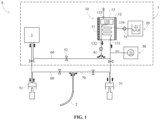
- the present invention relates to a total liquid ventilation (TLV) system S configured to deliver a breathable liquid to the lungs of a mammal, said TLV system S comprising a breathable liquid treatment unit 1, an inspiratory circuit 60, an expiratory circuit 70, and a pump assembly 5.
- TLV total liquid ventilation
- the breathable liquid comprises perfluorocarbons.
- Perfluorocarbons are particularly adapted for this purpose, as they are biocompatible, they have elevated oxygen and carbon dioxide solubility.
- FIG. 1 shows a TLV system S according to the invention.
- the breathable liquid treatment unit 1 allows to treat the breathable liquid circulating in the TLV system S.
- the treatment of the breathable liquid may comprise: removing carbon dioxide, adding oxygen, exchanging heat, or a combination thereof.
- the breathable liquid treatment unit 1 and its components will be later described.
- the inspiratory and expiratory circuits 60, 70 of the TLV system S comprise conduits in which the breathable liquid circulates.
- the pump assembly 5 comprises pumps 51 configured to move the breathable liquid through the conduits of the inspiratory and expiratory circuits 60, 70. More precisely, the pump assembly 5 comprises at least two pumps 51: an inspiratory pump 51 which is connected to the inspiratory circuit 60, and an expiratory pump 51 which is connected to the expiratory circuit 70.
- said inspiratory and expiratory pumps 51 may be piston pumps, as shown in figure 1 .
- an endotracheal tube 2 which is external to the TLV system S, is also illustrated.
- the endotracheal tube 2 is configured to be inserted in the trachea of the mammal.
- the inspiratory and expiratory circuits 60, 70 of the TLV system S are configured to be connected to the endotracheal tube 2.
- they may be configured to be connected to the endotracheal tube 2 via a Y-connector.
- connection with the endotracheal tube 2 permits to put the inspiratory and expiratory circuits 60, 70 of the TLV system S in communication with the respiratory system of the mammal. Therefore, the breathable liquid may be delivered from the inspiratory circuit 60 to the mammal's lung, and from the mammal's lung to the expiratory circuit 70, via the aforementioned inspiratory and expiratory pumps 51, respectively.
- the flow of the breathable liquid in the TLV system S when the system is connected to the endotracheal tube 2, comprises:
- the pump assembly 5 of the TLS system S further comprises a plurality of valves 52 configured to selectably allow the flow of the breathable liquid through predetermined portions of the inspiratory and expiratory circuits 60, 70.
- valves 52 may be located upstream and/or downstream of the components of the TLV system S, so as to selectably allow the flow of the breathable liquid through each component. For instance, one or more valves 52 may regulate the flow of the breathable liquid through the aforementioned breathable liquid treatment unit 1.
- the TLV system S may further comprise a plurality of sensors configured to measure physical variables of the breathable liquid circulating inside the TLV system S.
- the TLV system S may comprise temperature sensors, pressure sensors, flow meters, capnometers, oxygen sensors, and the like.
- the TLV system S may further comprise a controller.
- the controller is configured to receive the signals measured by the sensors, and to process said signal. For instance, the controller may compare the signal to a set of reference values. Then, the controller may control the breathable liquid treatment unit 1 and/or the pump assembly 5 of the TLV system S based on the result of said comparison.
- the control unit may further be configured to control the opening and the closing of the valves 52, so as to direct the flow of the breathable liquid in the fluid duct within selected compartments of the TLV system S.
- the TLV system may further comprise a buffer bag 3 (also called inspiratory buffer bag 3) having a buffer bag inlet and a buffer bag outlet.
- a buffer bag 3 also called inspiratory buffer bag 3 having a buffer bag inlet and a buffer bag outlet.
- the buffer bag inlet is connected to an outlet of the breathable liquid treatment unit 1, and the buffer bag outlet is connected to an inspiratory pump 51.
- the buffer bag 3 is configured to receive, via the expiratory pump 51, an expired breathable liquid.
- the bag 3 has the twofold function of a buffer bag, i.e., it helps to create and maintain a buffer, and of a storage bag, i.e., it is configured to contain and store a breathable liquid which fills the circuits of the TLV system S.
- the bag 3 is not configured to store the breathable liquid which fills the circuits of the TLV system S.
- the TLV system S comprises a separate bag, container, or box, for breathable liquid storage purposes.
- the buffer bag 3 has a volume comprised between 1 et 5 1.
- the breathable liquid treatment unit 1 will now be described in more details.
- the breathable liquid treatment unit 1 comprises:
- the heat exchange system 10 comprises at least one backing device 11 configured to provide mechanical support to the heat exchange system 10, and at least one plate 12 configured to be at a controlled temperature (i.e. a thermal plate).
- the heat exchange system 10 further comprises a bag 13 located in between the plate 12 and the backing device 11.
- the bag 13 comprises a fluid inlet 131, configured to be fluidly connected to the expiratory circuit 70, and a fluid outlet 132 configured to be fluidly connected to the inspiratory circuit 60 of the TLV system S.
- the fluid inlet 131 of the bag 13 is further configured to be connected to the gas injection system 30. In this case, it is possible to inject a gas mixture in the breathable liquid entering said inlet 131.
- the backing device 11, the at least one plate 12 and the bag 13 of the hat exchange system 10 are configured to define a fluid duct 134.
- Said fluid duct 134 extends between the fluid inlet 131 and the fluid outlet 132 of the bag 13. Said fluid duct 134 will be later described in more details.
- the at least one plate 12 is configured to be at a controlled temperature.
- said plate 12 is preferably made of a material with good thermal conductivity, such as for instance aluminum.
- the plate 12 by maintaining the plate 12 at a controlled temperature, it is possible to heat or cool the breathable liquid in the fluid duct 134, before introducing it in the inspiratory circuit 60.
- the controlled temperature of the plate 12 is lower than the temperature of the breathable liquid in the fluid duct 134, a heat transfer can occur from the breathable liquid in the fluid duct 134 to the plate 12. Consequently, the temperature of the breathable liquid in the fluid duct 134 is decreased.
- the controlled temperature of the plate 12 is higher than the temperature of the breathable liquid in the serpentine 134, a heat transfer can occur from the plate 12 to the breathable liquid in the fluid duct 134. Consequently, the temperature of the breathable liquid in the fluid duct 134 is increased.
- the rate of temperature change depends on the difference between the temperature of the breathable liquid in the fluid duct 134 and the temperature of the plate 12. More precisely, the temperature change is most rapid when said difference is higher.
- the TLV system S may comprise a controller.
- Said controller may be configured to control the temperature of the breathable liquid in the fluid duct 134 to ensure that it is comprised within a predetermined range.
- said predetermined range is between 20°C and 45°C.
- FIG. 1 illustrates a TLV system S in which the breathable liquid treatment unit 1 comprises a thermal unit 20.
- This thermal unit 20 comprises a tank 21 configured to contain a fluid (for instance, water) at a predetermined temperature.
- the pump assembly 5 of the TLV system S may further comprise one or more pumps 51 for pumping said fluid from the tank 21 of the thermal unit 20 towards the plate 12, so as to bring or maintain the plate 12 at a controlled temperature.
- the fluid is pumped from the tank 21 towards the plate 12 of the heat exchange system 10 at a predetermined flow rate.
- the plate 12 may comprise at least one internal channel fluidly connected to the tank 21 of the thermal unit 20.
- the plate 12 has a thickness which is large enough to host the internal channel.
- the internal channel preferably extends non-linearly inside the plate 12, but it has a plurality of folds, so as to cover the whole surface of the plate 12. This ensures that the whole plate 12 is heated or cooled at the desired temperature homogeneously.
- the plurality of folds does not cover the whole surface of the plate 12. This embodiment allows to obtain a heat exchange between the breathable liquid and the portion of the plate 12 comprising the channel.
- the internal channel may have a cross section having a diameter comprised between 1 mm and 20 mm.
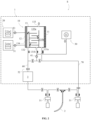
- FIG. 2 illustrates another TLV system S comprising a thermal unit 20 which comprise a first tank 21a and a second tank 21b configured to contain a cold fluid and a hot fluid, respectively.
- the controlled temperature of the plate 12 may be regulated for instance by modifying the flow rate of the fluids pumped towards the plate 12 and/or by modifying the temperature of the tanks 21a, 21b.
- the at least one plate 12 may comprise two internal channels: a first channel configured to receive the cold fluid from the first tank 21a, and a second channel configured to receive the hot fluid from the second tank 21b.
- the fluid in the tank 21a, 21b may be water.
- the first tank 21a preferably allows to maintain the water at a temperature comprised between 0°C and 20°, more preferably between 4°C and 10°C; whereas the second tank 21b preferably allows to maintain the water at a temperature comprised between 40°C and 90°C, more preferably between 40°C and 60°C.
- the plate 12 may comprise resistive elements or Peltier cells 22.
- said resistive elements or Peltier cells 22 may be mounted on a surface of the at least one plate 12.
- the heat exchange system10 may comprise a current source configured to feed the resistive elements or Peltier cells 22.
- the breathable liquid treatment unit 1 may not comprise thermal unit 20.
- the plate 12 is better shown on figure 3 , which shows an exploded view of a heat exchange system 10 of the invention.
- the plate 12 comprises a relief pattern. Therefore, when the bag 13 is sandwiched between the backing device 11 and the plate 12, the fluid duct 134 which is formed has the same shape as the relief pattern. More precisely, the dotted line of figure 3 represents the portion of the bag 13 which is compressed between the backing device 11 and the plate 12. The fluid duct 134 is formed inside said portion.
- the backing device 11 is configured to provide mechanical stability to the heat exchange system 10.
- said backing device 11 is preferably made of a hard material which is resistant to deformation.
- said backing device 11 may be made of steel.
- the backing device 11 may be a plate.
- it may be a plate parallel to the plate 12 configured to be at the controlled temperature.
- FIG 3 One example of this embodiment is illustrated in figure 3 .
- the backing device 11 and the plate 12 are separated by a constant distance.
- the distance between the backing device 11 and the plate 12 is comprised between 0 mm and 20 mm, more preferably between 4 mm and 15 mm.
- the breathable liquid treatment unit 1 comprises a backing device 11 and a plate 12.
- the breathable liquid treatment unit 1 may comprise more than one backing devices 11 and/or more than one plate 12 configured to be at the controlled temperature.
- the backing device 11 and the plate 12 may have a surface, on a vertical plane xz, which is equal or greater than the surface of the bag 13 on said plane.
- this embodiment ensures that the whole bag 13 is sandwiched between the backing device 11 and the plate 12.
- the backing device 11 and the plate 12 may have a surface which is smaller than the surface of the bag 13.
- this embodiment ensures that only a fraction of the breathable liquid present inside the sandwiched portion of the bag 13 can exchange heat with the plate 12.
- the backing device 11 may also be configured to be at a controlled temperature. For instance, it may be connected to the thermal unit 20.
- the fluid duct 134 is advantageously surrounded by components at the desired temperature (i.e., the backing device 11 and the plate 12). The area available for heat exchange is thus maximized.
- the bag 13 is sandwiched between the backing device 11 and the plate 12.
- the bag 13 is a disposable bag 13.
- a disposable bag 13 allows to minimize the manual operations, thereby reducing the risk of contaminations.
- the bag 13 may be a sterile bag, or it may be configured to be sterilized.
- the bag 13 has a volume comprised between 1 l and 7 l.
- the bag 13 comprises a first inlet 131 configured to receive a breathable liquid circulating in the expiratory circuit 70.
- the bag 13 comprises a fluid outlet 132 configured to evacuate the breathable liquid, once it has flowed through the fluid duct 134.
- the evacuated liquid due to is passage in the fluid duct 134, has a temperature and/or gas composition different from that of the liquid received at the first inlet 131.
- the bag 13 is configured to be inflated so that a target pressure is reached inside the fluid duct 134.
- the bag 13 is configured to be inflated up to 2 bar.
- two opposite surfaces of the bag 13 tend to be spaced apart, respectively towards the plate 12 and the backing device 11.
- the bag 13 may comprise two sheets joined together on their edges.
- a first sheet is moved towards the at least one plate 12, and a second sheet is moved towards the backing device 11.
- the bag 13 may be configured to be maintained at a temperature comprised between 10°C and 50°C.
- the bag 13 has a small thickness, preferably smaller than 1 mm; more preferably, smaller than 0.5 mm.
- the bag 13 is made of a material having a thermal resistance comprised between 0.05 and 0.5 W/mK, advantageously between 0.1 and 0.2 W/mK.
- the bag 13 may be made of a plastic material.
- it may be made of polyurethane, for instance thermoplastic polyurethane (TPU).
- TPU thermoplastic polyurethane
- Polyurethane is resistant to heat and pressure. Moreover, it has a low thermal resistance.
- the bag 13 may be made of ethylene vinyl acetate (EVA), or polyvinyl chloride (PVC).
- EVA ethylene vinyl acetate
- PVC polyvinyl chloride
- a bag 13 made of a material with low thermal resistance, and/or having a small thickness allows to reduce the thermal contact resistance between the bag 13 and the plate 12. Indeed, the thermal contact resistance between contacting surfaces is also affected by the material and the thickness of the contacting surfaces.
- the bag 13 further comprises a gas outlet 133 configured to expel a gas from the fluid duct 134.
- the gas outlet 133 is configured to expel a gas from a reservoir 135 communicating with the fluid duct 134.
- the gas outlet 133 allows to remove CO 2 from the breathable liquid in the fluid duct 134, so that the breathable liquid introduced in the inspiratory circuit 60 via the first outlet 132 of the bag 13 is a CO 2 -deprived two-phase mixture.
- a fraction of the CO 2 present in the fluid duct may be evacuated from the gas outlet 133.
- all the CO 2 present in the fluid duct is evacuated via the gas outlet 133.
- a capnometer may be installed at the gas outlet 133, so as to measure the concentration of CO 2 in the evacuated gas.
- a pressure control valve may be mounted on the gas outlet 133 of the bag 13. The pressure control valve allows to increase or decrease the amount of gas which is expelled from the gas outlet 133.
- some other gas may be evacuated via the gas outlet 133.
- some O 2 may be expelled from the gas outlet 133.
- the bag 13 may have more than one fluid inlet 131 and/or more than one fluid outlet 132.
- FIG. 4 shows a TLS system S in which the bag 13 has one fluid port 131a, one fluid inlet 131b and two fluids outlet 132a, 132b.
- the fluid port 131a is advantageously configured to allow a bidirectional flow of the breathable liquid.
- the bag 13 comprises:
- the gas injection system 30 The gas injection system 30
- the breathable liquid treatment unit 1 also comprises a gas injection system 30.
- the gas injection system 30 is configured to be connected to an inlet of the bag 13.
- the gas injection system 30 is configured to inflate the bag 13. More precisely, the gas injection system 30 is configured to inject the breathable liquid comprising the gas mixture in the fluid inlet 131 of the bag 13, so as to inflate said bag 13 until a target pressure is reached inside the fluid duct 134.
- the gas injection system 30 provide a twofold advantage: (i) it allows to reach, inside the fluid duct 134, the target pressure which optimizes the heat exchange between the breathable liquid and the plate 12, and (ii) it allows to introduce the gas mixture in the breathable liquid which is in the fluid duct 134.
- the injection of the gas mixture into the breathable liquid allows to obtain a two-phase mixture comprising the injected gas mixture and the breathable liquid.
- the gas injection system 30 allows to obtain heat transfer and gas exchange to the breathable liquid in the fluid duct 134, simultaneously.
- the gas injection system 30 may be configured to inject air, preferably medical air.
- the gas injection system 30 may be configured to inject a mixture of air and O 2 .
- the bag 13 comprises a gas outlet 133 configured to expel a gas separated from the breathable liquid. In some cases, some O 2 may also be expelled from said gas outlet 133.
- the amount of O 2 expelled from the gas outlet 133 depends on the composition of the gas injected in the fluid duct 134 by the gas injection system 30. The higher is the concentration of O 2 in the injected gas, the higher the amount of O 2 expelled.
- the gas injection system 30 is configured to inject a gas mixture comprising O 2 in a concentration between 21% and 100%.
- the concentration of O 2 in the breathable liquid can be controlled on the basis of the concentration of O 2 in the injected gas.
- the gas injection system 30 may comprise a mixing chamber 31 which comprises a nozzle configured to generate gas micro-bubbles.
- the nozzle may be a Venturi-type nozzle.
- micro-bubbles gas bubbles having a diameter smaller than 10 mm.
- said micro-bubble size may be obtained via a turbulent flow regimen.
- This micro-bubble size ensures that the bubbles are uniformly distributed in the two-phase mixture, thereby optimizing the heat exchange. Moreover, bubbles of this size have an equivalent surface which maximizes the gas exchange.
- the breathable liquid treatment unit 1 further comprises a pumping system 40.
- the pumping system 40 comprises a pump 41 configured to inject the breathable liquid in the fluid duct 134 via the fluid inlet 131.
- said pump 41 may be a centrifugal pump.
- the breathable liquid treatment unit 1 comprises a recirculating circuit configured to connect the fluid outlet 132 and the fluid inlet 131 so as to define a closed circuit with the fluid duct 134, and the circulation of the breathable liquid inside said recirculating circuit is ensured by the pump 41 of the pumping system 40.
- the circulation of the breathable liquid inside the recirculating circuit comprises:
- the treated breathable liquid inside the fluid duct 134 via the fluid inlet 131 By reinjecting, by means of the pump 41 of the pumping system 40, the treated breathable liquid inside the fluid duct 134 via the fluid inlet 131, it is possible to provide several successive treatments (for instance: carbon dioxide removal, oxygen addition, heat exchange or a combination thereof) to the breathable liquid, before introducing it in the inspiratory circuit 60.
- several successive treatments for instance: carbon dioxide removal, oxygen addition, heat exchange or a combination thereof
- the number of treatments per minute depends on the flow rate at which the breathable liquid is pumped by the pump 41.
- each of: the inspiratory circuit 60, the expiratory circuit 70, and the recirculating circuit comprise at least one valve 52 (referenced only once in each figure for clarity sake).
- the valve opening and closure allow to force or to block the circulation of the breathable liquid inside the recirculating circuit.
- the pump 41 is located upstream of the gas exchange system 30 in the recirculating circuit.
- the pump 41 is located downstream of the gas exchange system, or it is combined with said gas exchange system 30.
- the breathable liquid is pumped by the pump 41 of the pumping system 40 from the fluid outlet 132 to the fluid inlet 131 at a predetermined flow rate.
- the bag 13 may have more than one fluid ports, inlets and/or outlets 131a, 131b 132a, 132b.
- the pump 41 is configured to pump the breathable liquid from at least one fluid outlet 132a, 132b to a fluid inlet 131, 131b.
- FIG. 4 One example of this embodiment is show in figure 4 .
- the recirculating circuit puts in communication the fluid outlet 132b with the fluid inlet 131b.
- the direction of circulation of the breathable liquid inside the recirculating circuit also depends on the opening and closure of the valves 52.
- Figure 5 is a diagram illustrating schematically the recirculating circuit in more details.
- FIG. 5A the valves block the circulation of the breathable liquid in the recirculation circuit. Therefore, the breathable liquid circulates in the expiratory circuit 70, then in the fluid duct 134, then in the inspiratory circuit 60.
- Figures 5B-5C shows the circulation of the breathable liquid in the recirculation circuit in a first direction and in a second direction, respectively.
- valves 52, and the fluid duct 134 inside the bag 13 are not illustrated for intelligibility purposes.
- the fluid duct 134 The fluid duct 134
- the fluid duct 134 is compressed between the plate 12 and the backing device 11. Therefore, a large surface of the fluid duct 134 is in contact with the plate 12 at the controlled temperature. This large contact surface allows to achieve a heat transfer which is much faster when compared to tubular heat exchange system, in which only a limited portion of the fluid duct is in contact with cold or hot pipes.
- the fluid duct 134 extends between the fluid inlet 131 and the fluid outlet 132 of the bag 13, and it has a length L which is longer than the distance between said fluid inlet and outlet 131, 132.
- the length L of the fluid duct 134 is at least twice the distance between the fluid inlet 131 and the fluid outlet 132.
- the bag 13 may comprise two sheets joined together on their edges.
- the length L of the fluid duct 134 is preferably more than twice the longest edge of the sheets.
- the fluid duct 134 may comprise a serpentine-shaped portion, a spiral-shaped portion, or a combination thereof. These embodiments allow to obtain a fluid duct 134 inside the bag 13 which is longer more than twice the distance between the fluid inlet 131 and the fluid outlet 132.
- a long fluid duct 134 allows to increase the residence time of the breathable liquid in the heat exchange system 10, and to achieve a better separation of the gas.
- the volume of the fluid duct 134 is comprised between 0.81 and 1.5 l.
- the fluid duct 134 may advantageously comprise a reservoir 135, 135a fluidly connected to the gas outlet 133.
- the fluid reservoir 135 has a volume comprised between 0.1 1 and 1 l.
- the fluid reservoir 135, 135a is configured to separate a gas from the breathable liquid. More precisely, the reservoir 135, 135a ensures the separation of a gas from the breathable liquid and it also allows to contain the gas after separation (i.e., the gas removed from the breathable liquid). For instance, the reservoir may be located at the top of the serpentine in a vertical direction, i.e., a direction parallel to the local gravity direction, so as to take advantage of the gravity to separate the gas from the breathable liquid.
- a pressure control valve may be mounted on the gas outlet 133 of the bag 13.
- the pressure control valve is configured to regulate the pressure in the reservoir 135. By modifying the pressure in the reservoir 135, it is possible to increase or decrease the amount of gas which is expelled from the gas outlet 133.
- the pressure control valve is configured to regulate the pressure in the reservoir 135 so that it is in a range comprised between 0.1 bar and 0.4 bar.
- the TLS system S may further comprise a second reservoir 135b (also called expiratory reservoir or expiratory buffer bag) fluidly connected to the fluid port 131a of the bag 13.
- a second reservoir 135b also called expiratory reservoir or expiratory buffer bag
- This embodiment advantageously allows to obtain a constant flow rate of the breathable liquid inside the fluid duct 134 and in the gas exchange system, thereby improving the heat and gas exchange occurring in said fluid duct.
- the constant flow rate may be comprised between 10 l/min and 15 l/min. In absence of the second reservoir 135b, the flow rate would not be constant. More precisely, the flow rate would be lower when the expiratory pump 51 is off, and it would be greater when the expiratory pump 51 is on.
- Figure 6 shows a second reservoir 135b integrated in the bag 13.
- said second reservoir 135b may be external to the bag 13.
- the second reservoir 135b also prevents an overload of the expiratory pump 51.
- the fluid port 131a allows the breathable liquid to be introduced inside the second reservoir before reaching the fluid duct.
- the second reservoir 135b may be configured to be filled with the breathable liquid, which has flown in the fluid duct 134, by overflow.
- the second reservoir 135b has a volume greater than 1 l and up to 4,5 l.
- the second reservoir 135b may have a volume comprised between 31 and 3,5 1.
- the fluid duct 134 may further comprise a third reservoir 135c (also called inspiratory reservoir or inspiratory buffer bag) fluidly connected to the fluid outlet 132a of the bag 13. Said third reservoir 135c may be filled with the breathable liquid which has flown in the fluid duct 134 by overflow.
- a third reservoir 135c also called inspiratory reservoir or inspiratory buffer bag
- TLV system S does not require the presence of buffer bags 3. Therefore, the volume of breathable liquid circulating liquid inside the TLV system S is reduced, and the inspiratory circuit 60 is shorter.
- the third reservoir 135c further allows to minimize the thermal losses because the breathable liquid which has been treated in the breathable liquid treatment unit 1 can reach more rapidly the inspiratory pump 51.
- the third reservoir 135c is integrated in the bag 13.
- said third reservoir 135c may be external to the bag 13.
- a bag 13 having more than one of the reservoirs 135, 135a, 135b, 135c described hereabove allows to obtain a "all-in-one" bag 13.
- the "all-in-one" bag 13 of figure 6 comprises a reservoir 135a for separating a gas from the breathable liquid, a second reservoir 135b and a third reservoirs 135c.
- the second and third reservoirs 135b, 135c do not exchange heat with the plate 12.
- the plate 12 may be smaller than the bag, so that only the portion of the bag 13 comprising the fluid duct 134 is sandwiched between the plate 12 and the backing device 11.
- the plate 12 may comprise a relief patter. Said pattern is on a surface of the plate 12 which faces the bag 13.
- the pattern on the plate 12 may be a recess pattern.
- the fluid duct 134 is defined by the portion of the bag 13 which is sandwiched between the backing device 11 and the relief pattern on the plate 12. In this case, when the two-phase mixture is injected in the bag 13, two opposite surfaces of the bag 13 are spaced apart where the relief pattern is not present.
- the thickness of the relief pattern is preferably comprised between 5 mm and 15 mm.
- the thickness of the relief pattern is preferably comprised between 5 mm and 15 mm.
- the depth of the recesses is preferably comprised between 5 mm and 15 mm.
- the backing device 11 and/or on the bag 13 may comprise a pattern.
- the backing device 11 may comprise a pattern complimentary to the pattern on the at least one plate 12.
- FIG. 5 One example of a pattern on the bag 13 is illustrated in figure 5 .
- the bag 13 has two surfaces joined together on their edges. Said surfaces are further joined together along a sealed boundary (for instance, heat sealed) comprised inside their edges.
- the pattern is defined by the sealed boundary.
- the pattern on the bag 13 is configured to define an inflatable compartment within the bag 13, corresponding to the non-sealed portion of the bag 13 and delimited by the sealed boundary.
- Said inflatable compartment is configured to be inflated by the gas injection system 30.
- the remaining portion of the bag 13, i.e., the portion external to the sealed boundary, is not inflated.
- having the pattern on the bag 13 allows to improve the tightness of the fluid duct 134, thanks to the sealed boundary. Therefore, this embodiment prevents the leaking of the breathable liquid out of the fluid duct 134.
- figure 6 shows a bag 13 comprising a serpentine pattern and three reservoir patterns, so as to define a fluid duct 134 comprising a serpentine duct 134 and three reservoirs 135a, 135b, 135c.
- the reservoirs 135a, 135b, 135c may be external to the bag 13.
- the bag 13 of figure 6 may be located between a backing device 11 and a plate 12 which do not comprise any patter.
- the backing device 11 and/or the plate 12 may comprise a pattern complimentary to the pattern on the bag 13 so as to increase the contact surface.
- the plate 12 is brought at the desired controlled temperature.
- step S10 the gas injection system 30 injects a gas mixture comprising oxygen into the breathable liquid, so as to obtain a two-phase mixture comprising the gas mixture and the breathable liquid.
- the gas injection system 30 injects the gas mixture through the fluid inlet 131 of the bag 13.
- the injection step S30 allows to inflate the bag 13.
- a pump 51 of the pump assembly 5 pumps a breathable liquid in the fluid duct 134 through the fluid inlet 131 of the bag 13.
- Steps S20 and S30 may be performed simultaneously.
- the step S10 of introducing a gas mixture comprising oxygen into the breathable liquid may comprise:
- step S40 the two-phase mixture is conducted from the fluid inlet 131 to the fluid outlet 132 of the bag 13.
- step S40 a gas may also be evacuated from the gas outlet 133 of the bag 13.
- step S40 further comprises:
- CO 2 deprived it is meant that the CO 2 concentration in the two-phase mixture collected at the fluid outlet 132 is less than half of the initial CO 2 concentration, i.e. than the CO 2 concentration in the breathable liquid.
- the gas evacuation step allows to obtain a simultaneous oxygenation of an expired breathing liquid, via the injection of oxygen in step S30, and CO 2 removal via the gas outlet 133.
- a CO 2 -deprived breathable liquid can be collected at the fluid outlet 132, and introduced in the inspiratory circuit 60 of the TLV system S.
- the gas mixture is injected in the fluid inlet 131 of the bag 13 at a flow rate comprised between 0 L/min and 20 L/min, more preferably between 10 l/min and 15 l/min.
- O 2 and CO 2 time constant it is meant the amount of time needed to increase the O 2 concentration by 67% and decrease the CO 2 concentration by 67% in the breathable liquid.
- the breathable liquid is pumped by the pump 41 of the pumping system 40 from the fluid outlet 132 to the fluid inlet 131 of the bag 13.
- This step allows to circulate the breathable liquid inside a closed circuit comprising the fluid duct 134 and the recirculating circuit. Therefore, the breathable liquid can circulate a predetermined number of times inside said closed circuit, before being introduced in the inspiratory circuit 60 in a step S60.
- step S60 the treated breathable liquid is introduced in the inspiratory circuit 60 of the TLV system S. Therefore, said treated breathable liquid can be injected into the endotracheal tube 2 by means of the inspiratory pump 51.
- the temperature of the plate 12 is monitored.
- the temperature of the plate 12 is continuously monitored.
- the temperature of the plate 12 is modified.
- the temperature of the plate 12 is modified depending on the desired temperature of the breathable liquid.
- the temperature of the plate 12 is further modified based on the desired rate of temperature change of said breathable liquid.
- the temperature of the plate 12 in order to obtain a rapid decrease of the temperature of the breathable liquid in the fluid duct 134, the temperature of the plate 12 can be controlled to be as low as 0°C. In order to obtain a rapid increase of the temperature of the breathable liquid in the fluid duct 134, the temperature of the plate 12 can be controlled to be as high as 60°C. In order to maintain the temperature of the breathable liquid in the fluid duct 134 constant, the temperature of the plate 12 is controlled so as to be equal to the temperature of the breathable liquid in the fluid duct 134.
Landscapes
- Health & Medical Sciences (AREA)
- Pulmonology (AREA)
- General Health & Medical Sciences (AREA)
- Public Health (AREA)
- Veterinary Medicine (AREA)
- Biomedical Technology (AREA)
- Heart & Thoracic Surgery (AREA)
- Engineering & Computer Science (AREA)
- Life Sciences & Earth Sciences (AREA)
- Animal Behavior & Ethology (AREA)
- Hematology (AREA)
- Emergency Medicine (AREA)
- Anesthesiology (AREA)
- Vascular Medicine (AREA)
- External Artificial Organs (AREA)
- Infusion, Injection, And Reservoir Apparatuses (AREA)
- Thermotherapy And Cooling Therapy Devices (AREA)
- Physics & Mathematics (AREA)
- Thermal Sciences (AREA)
- Percussion Or Vibration Massage (AREA)
- Devices For Medical Bathing And Washing (AREA)
Priority Applications (8)
| Application Number | Priority Date | Filing Date | Title |
|---|---|---|---|
| EP21305533.8A EP4079355B1 (en) | 2021-04-23 | 2021-04-23 | Total liquid ventilation system and method |
| PL21305533.8T PL4079355T3 (pl) | 2021-04-23 | 2021-04-23 | Układ i sposób całkowitej wentylacji cieczowej |
| US18/556,720 US20240189528A1 (en) | 2021-04-23 | 2022-04-22 | Total liquid ventilation system and method |
| CN202280030414.1A CN117597166A (zh) | 2021-04-23 | 2022-04-22 | 全液体通气系统及方法 |
| JP2023565198A JP2024517429A (ja) | 2021-04-23 | 2022-04-22 | 完全液体換気システムおよび方法 |
| KR1020237039037A KR20240004510A (ko) | 2021-04-23 | 2022-04-22 | 전체 액체 환기 시스템 및 방법 |
| CA3215042A CA3215042A1 (en) | 2021-04-23 | 2022-04-22 | Total liquid ventilation system and method |
| PCT/EP2022/060645 WO2022223751A1 (en) | 2021-04-23 | 2022-04-22 | Total liquid ventilation system and method |
Applications Claiming Priority (1)
| Application Number | Priority Date | Filing Date | Title |
|---|---|---|---|
| EP21305533.8A EP4079355B1 (en) | 2021-04-23 | 2021-04-23 | Total liquid ventilation system and method |
Publications (3)
| Publication Number | Publication Date |
|---|---|
| EP4079355A1 EP4079355A1 (en) | 2022-10-26 |
| EP4079355C0 EP4079355C0 (en) | 2024-05-29 |
| EP4079355B1 true EP4079355B1 (en) | 2024-05-29 |
Family
ID=75825757
Family Applications (1)
| Application Number | Title | Priority Date | Filing Date |
|---|---|---|---|
| EP21305533.8A Active EP4079355B1 (en) | 2021-04-23 | 2021-04-23 | Total liquid ventilation system and method |
Country Status (8)
| Country | Link |
|---|---|
| US (1) | US20240189528A1 (pl) |
| EP (1) | EP4079355B1 (pl) |
| JP (1) | JP2024517429A (pl) |
| KR (1) | KR20240004510A (pl) |
| CN (1) | CN117597166A (pl) |
| CA (1) | CA3215042A1 (pl) |
| PL (1) | PL4079355T3 (pl) |
| WO (1) | WO2022223751A1 (pl) |
Family Cites Families (16)
| Publication number | Priority date | Publication date | Assignee | Title |
|---|---|---|---|---|
| CA2144442A1 (en) * | 1993-07-12 | 1995-01-26 | Otsuka Pharmaceutical Factory, Inc. | Cooler for plasma cooling bags |
| US6041777A (en) * | 1995-12-01 | 2000-03-28 | Alliance Pharmaceutical Corp. | Methods and apparatus for closed-circuit ventilation therapy |
| US6105572A (en) * | 1997-11-07 | 2000-08-22 | Alliance Pharmaceutical Corp. | Liquid ventilator |
| US6149624A (en) * | 1998-02-05 | 2000-11-21 | Mcshane; Richard Houston | Apparatus and method for the rapid induction of hypothermic brain preservation |
| US6673098B1 (en) * | 1998-08-24 | 2004-01-06 | Radiant Medical, Inc. | Disposable cassette for intravascular heat exchange catheter |
| US6694977B1 (en) * | 1999-10-01 | 2004-02-24 | Critical Care Research, Inc. | Mixed-mode liquid ventilation gas and heat exchange |
| US20020023640A1 (en) * | 2000-05-12 | 2002-02-28 | Chris Nightengale | Respiratory apparatus including liquid ventilator |
| US20020153010A1 (en) * | 2001-04-23 | 2002-10-24 | Rozenberg Allan L. | System and method for total liquid ventilation with very low priming volume |
| WO2004082729A2 (en) * | 2003-03-17 | 2004-09-30 | Aga Ab | Method and apparatus for changing the body temperature of a mammal |
| JP5713406B2 (ja) * | 2008-12-02 | 2015-05-07 | クール セラピューティクス, インコーポレイテッド | 微細氷粒子を有する呼吸ガスの送達のためのシステム |
| US9439804B2 (en) * | 2011-03-03 | 2016-09-13 | Renaud Tissier | Method and system for treatment of a body of a mammal in cardiac arrest |
| US11253392B2 (en) * | 2011-09-28 | 2022-02-22 | Zoll Circulation, Inc. | Endovascular cooling catheter system which employs phase-changing heat exchange media |
| US10500088B2 (en) * | 2014-02-14 | 2019-12-10 | Zoll Circulation, Inc. | Patient heat exchange system with two and only two fluid loops |
| US10022265B2 (en) * | 2015-04-01 | 2018-07-17 | Zoll Circulation, Inc. | Working fluid cassette with hinged plenum or enclosure for interfacing heat exchanger with intravascular temperature management catheter |
| CN109310843A (zh) * | 2016-04-27 | 2019-02-05 | 赛斯安尼股份有限公司 | 用于将流体和/或气体递送到肺的设备和方法 |
| EP3400975B1 (en) * | 2017-05-11 | 2020-10-14 | Gambro Lundia AB | Container for fluids and apparatus for warming medical fluids |
-
2021
- 2021-04-23 PL PL21305533.8T patent/PL4079355T3/pl unknown
- 2021-04-23 EP EP21305533.8A patent/EP4079355B1/en active Active
-
2022
- 2022-04-22 US US18/556,720 patent/US20240189528A1/en active Pending
- 2022-04-22 CA CA3215042A patent/CA3215042A1/en active Pending
- 2022-04-22 WO PCT/EP2022/060645 patent/WO2022223751A1/en not_active Ceased
- 2022-04-22 JP JP2023565198A patent/JP2024517429A/ja active Pending
- 2022-04-22 CN CN202280030414.1A patent/CN117597166A/zh active Pending
- 2022-04-22 KR KR1020237039037A patent/KR20240004510A/ko active Pending
Also Published As
| Publication number | Publication date |
|---|---|
| CA3215042A1 (en) | 2022-10-27 |
| CN117597166A (zh) | 2024-02-23 |
| JP2024517429A (ja) | 2024-04-22 |
| PL4079355T3 (pl) | 2024-11-04 |
| EP4079355A1 (en) | 2022-10-26 |
| US20240189528A1 (en) | 2024-06-13 |
| KR20240004510A (ko) | 2024-01-11 |
| WO2022223751A1 (en) | 2022-10-27 |
| EP4079355C0 (en) | 2024-05-29 |
Similar Documents
| Publication | Publication Date | Title |
|---|---|---|
| EP3650057B1 (en) | Systems and methods for treating blood | |
| AU713362B2 (en) | Liquid ventilation method and apparatus | |
| US8734375B2 (en) | Blood treatment method adapted to at least partially eliminate the carbon dioxide content and related device | |
| US8672867B2 (en) | Cardiopulmonary bypass devices and methods | |
| EP2192879B1 (en) | Portable apparatus and method for the administration of heat exchange in the lungs of a mammal | |
| US12285557B2 (en) | Systems and methods for treating blood | |
| US10946134B2 (en) | Systems and methods for treating blood | |
| ES3014221T3 (en) | Medical fluid therapy machine including pneumatic pump box and accumulators therefore | |
| US20250186670A1 (en) | Systems and Methods for Treating Blood | |
| EP4079355B1 (en) | Total liquid ventilation system and method | |
| WO2018144970A1 (en) | Systems and methods for treating blood | |
| US9314366B2 (en) | Surgical heating and cooling system and devices and methods for the use thereof | |
| CN222917884U (zh) | 供氧设备 | |
| CN217793942U (zh) | 医用crrt置换液调温袋 | |
| JPS62691Y2 (pl) | ||
| CN121846411A (zh) | 改良超滤保温设备 | |
| JPS63174664A (ja) | 人工肺用多層式貯血槽 |
Legal Events
| Date | Code | Title | Description |
|---|---|---|---|
| PUAI | Public reference made under article 153(3) epc to a published international application that has entered the european phase |
Free format text: ORIGINAL CODE: 0009012 |
|
| STAA | Information on the status of an ep patent application or granted ep patent |
Free format text: STATUS: THE APPLICATION HAS BEEN PUBLISHED |
|
| AK | Designated contracting states |
Kind code of ref document: A1 Designated state(s): AL AT BE BG CH CY CZ DE DK EE ES FI FR GB GR HR HU IE IS IT LI LT LU LV MC MK MT NL NO PL PT RO RS SE SI SK SM TR |
|
| STAA | Information on the status of an ep patent application or granted ep patent |
Free format text: STATUS: REQUEST FOR EXAMINATION WAS MADE |
|
| 17P | Request for examination filed |
Effective date: 20230426 |
|
| RBV | Designated contracting states (corrected) |
Designated state(s): AL AT BE BG CH CY CZ DE DK EE ES FI FR GB GR HR HU IE IS IT LI LT LU LV MC MK MT NL NO PL PT RO RS SE SI SK SM TR |
|
| REG | Reference to a national code |
Ref country code: DE Ref legal event code: R079 Free format text: PREVIOUS MAIN CLASS: A61M0016000000 Ipc: A61F0007000000 Ref document number: 602021013803 Country of ref document: DE |
|
| RIC1 | Information provided on ipc code assigned before grant |
Ipc: A61M 16/04 20060101ALI20230615BHEP Ipc: A61F 7/12 20060101ALI20230615BHEP Ipc: A61M 16/00 20060101ALI20230615BHEP Ipc: A61F 7/00 20060101AFI20230615BHEP |
|
| GRAP | Despatch of communication of intention to grant a patent |
Free format text: ORIGINAL CODE: EPIDOSNIGR1 |
|
| STAA | Information on the status of an ep patent application or granted ep patent |
Free format text: STATUS: GRANT OF PATENT IS INTENDED |
|
| INTG | Intention to grant announced |
Effective date: 20230727 |
|
| GRAJ | Information related to disapproval of communication of intention to grant by the applicant or resumption of examination proceedings by the epo deleted |
Free format text: ORIGINAL CODE: EPIDOSDIGR1 |
|
| STAA | Information on the status of an ep patent application or granted ep patent |
Free format text: STATUS: REQUEST FOR EXAMINATION WAS MADE |
|
| GRAP | Despatch of communication of intention to grant a patent |
Free format text: ORIGINAL CODE: EPIDOSNIGR1 |
|
| STAA | Information on the status of an ep patent application or granted ep patent |
Free format text: STATUS: GRANT OF PATENT IS INTENDED |
|
| INTC | Intention to grant announced (deleted) | ||
| INTG | Intention to grant announced |
Effective date: 20231212 |
|
| GRAS | Grant fee paid |
Free format text: ORIGINAL CODE: EPIDOSNIGR3 |
|
| GRAA | (expected) grant |
Free format text: ORIGINAL CODE: 0009210 |
|
| STAA | Information on the status of an ep patent application or granted ep patent |
Free format text: STATUS: THE PATENT HAS BEEN GRANTED |
|
| AK | Designated contracting states |
Kind code of ref document: B1 Designated state(s): AL AT BE BG CH CY CZ DE DK EE ES FI FR GB GR HR HU IE IS IT LI LT LU LV MC MK MT NL NO PL PT RO RS SE SI SK SM TR |
|
| REG | Reference to a national code |
Ref country code: CH Ref legal event code: EP |
|
| REG | Reference to a national code |
Ref country code: IE Ref legal event code: FG4D |
|
| REG | Reference to a national code |
Ref country code: DE Ref legal event code: R096 Ref document number: 602021013803 Country of ref document: DE |
|
| U01 | Request for unitary effect filed |
Effective date: 20240617 |
|
| REG | Reference to a national code |
Ref country code: NL Ref legal event code: MP Effective date: 20240529 |
|
| U07 | Unitary effect registered |
Designated state(s): AT BE BG DE DK EE FI FR IT LT LU LV MT NL PT RO SE SI Effective date: 20240902 |
|
| PG25 | Lapsed in a contracting state [announced via postgrant information from national office to epo] |
Ref country code: IS Free format text: LAPSE BECAUSE OF FAILURE TO SUBMIT A TRANSLATION OF THE DESCRIPTION OR TO PAY THE FEE WITHIN THE PRESCRIBED TIME-LIMIT Effective date: 20240929 |
|
| PG25 | Lapsed in a contracting state [announced via postgrant information from national office to epo] |
Ref country code: HR Free format text: LAPSE BECAUSE OF FAILURE TO SUBMIT A TRANSLATION OF THE DESCRIPTION OR TO PAY THE FEE WITHIN THE PRESCRIBED TIME-LIMIT Effective date: 20240529 |
|
| PG25 | Lapsed in a contracting state [announced via postgrant information from national office to epo] |
Ref country code: GR Free format text: LAPSE BECAUSE OF FAILURE TO SUBMIT A TRANSLATION OF THE DESCRIPTION OR TO PAY THE FEE WITHIN THE PRESCRIBED TIME-LIMIT Effective date: 20240830 |
|
| PG25 | Lapsed in a contracting state [announced via postgrant information from national office to epo] |
Ref country code: ES Free format text: LAPSE BECAUSE OF FAILURE TO SUBMIT A TRANSLATION OF THE DESCRIPTION OR TO PAY THE FEE WITHIN THE PRESCRIBED TIME-LIMIT Effective date: 20240529 |
|
| PG25 | Lapsed in a contracting state [announced via postgrant information from national office to epo] |
Ref country code: NO Free format text: LAPSE BECAUSE OF FAILURE TO SUBMIT A TRANSLATION OF THE DESCRIPTION OR TO PAY THE FEE WITHIN THE PRESCRIBED TIME-LIMIT Effective date: 20240829 Ref country code: IS Free format text: LAPSE BECAUSE OF FAILURE TO SUBMIT A TRANSLATION OF THE DESCRIPTION OR TO PAY THE FEE WITHIN THE PRESCRIBED TIME-LIMIT Effective date: 20240929 Ref country code: HR Free format text: LAPSE BECAUSE OF FAILURE TO SUBMIT A TRANSLATION OF THE DESCRIPTION OR TO PAY THE FEE WITHIN THE PRESCRIBED TIME-LIMIT Effective date: 20240529 Ref country code: GR Free format text: LAPSE BECAUSE OF FAILURE TO SUBMIT A TRANSLATION OF THE DESCRIPTION OR TO PAY THE FEE WITHIN THE PRESCRIBED TIME-LIMIT Effective date: 20240830 Ref country code: ES Free format text: LAPSE BECAUSE OF FAILURE TO SUBMIT A TRANSLATION OF THE DESCRIPTION OR TO PAY THE FEE WITHIN THE PRESCRIBED TIME-LIMIT Effective date: 20240529 Ref country code: RS Free format text: LAPSE BECAUSE OF FAILURE TO SUBMIT A TRANSLATION OF THE DESCRIPTION OR TO PAY THE FEE WITHIN THE PRESCRIBED TIME-LIMIT Effective date: 20240829 |
|
| PG25 | Lapsed in a contracting state [announced via postgrant information from national office to epo] |
Ref country code: CZ Free format text: LAPSE BECAUSE OF FAILURE TO SUBMIT A TRANSLATION OF THE DESCRIPTION OR TO PAY THE FEE WITHIN THE PRESCRIBED TIME-LIMIT Effective date: 20240529 |
|
| PG25 | Lapsed in a contracting state [announced via postgrant information from national office to epo] |
Ref country code: SK Free format text: LAPSE BECAUSE OF FAILURE TO SUBMIT A TRANSLATION OF THE DESCRIPTION OR TO PAY THE FEE WITHIN THE PRESCRIBED TIME-LIMIT Effective date: 20240529 |
|
| PG25 | Lapsed in a contracting state [announced via postgrant information from national office to epo] |
Ref country code: SM Free format text: LAPSE BECAUSE OF FAILURE TO SUBMIT A TRANSLATION OF THE DESCRIPTION OR TO PAY THE FEE WITHIN THE PRESCRIBED TIME-LIMIT Effective date: 20240529 |
|
| PG25 | Lapsed in a contracting state [announced via postgrant information from national office to epo] |
Ref country code: SM Free format text: LAPSE BECAUSE OF FAILURE TO SUBMIT A TRANSLATION OF THE DESCRIPTION OR TO PAY THE FEE WITHIN THE PRESCRIBED TIME-LIMIT Effective date: 20240529 Ref country code: SK Free format text: LAPSE BECAUSE OF FAILURE TO SUBMIT A TRANSLATION OF THE DESCRIPTION OR TO PAY THE FEE WITHIN THE PRESCRIBED TIME-LIMIT Effective date: 20240529 Ref country code: CZ Free format text: LAPSE BECAUSE OF FAILURE TO SUBMIT A TRANSLATION OF THE DESCRIPTION OR TO PAY THE FEE WITHIN THE PRESCRIBED TIME-LIMIT Effective date: 20240529 |
|
| PLBE | No opposition filed within time limit |
Free format text: ORIGINAL CODE: 0009261 |
|
| STAA | Information on the status of an ep patent application or granted ep patent |
Free format text: STATUS: NO OPPOSITION FILED WITHIN TIME LIMIT |
|
| 26N | No opposition filed |
Effective date: 20250303 |
|
| U20 | Renewal fee for the european patent with unitary effect paid |
Year of fee payment: 5 Effective date: 20250425 |
|
| PGFP | Annual fee paid to national office [announced via postgrant information from national office to epo] |
Ref country code: GB Payment date: 20250423 Year of fee payment: 5 |
|
| PGFP | Annual fee paid to national office [announced via postgrant information from national office to epo] |
Ref country code: CH Payment date: 20250501 Year of fee payment: 5 |
|
| PGFP | Annual fee paid to national office [announced via postgrant information from national office to epo] |
Ref country code: IE Payment date: 20250422 Year of fee payment: 5 |
|
| PG25 | Lapsed in a contracting state [announced via postgrant information from national office to epo] |
Ref country code: MC Free format text: LAPSE BECAUSE OF FAILURE TO SUBMIT A TRANSLATION OF THE DESCRIPTION OR TO PAY THE FEE WITHIN THE PRESCRIBED TIME-LIMIT Effective date: 20240529 |
|
| PGFP | Annual fee paid to national office [announced via postgrant information from national office to epo] |
Ref country code: PL Payment date: 20260326 Year of fee payment: 6 |