EP4079248A1 - Medical robot and mounting part of medical robot - Google Patents
Medical robot and mounting part of medical robot Download PDFInfo
- Publication number
- EP4079248A1 EP4079248A1 EP20901910.8A EP20901910A EP4079248A1 EP 4079248 A1 EP4079248 A1 EP 4079248A1 EP 20901910 A EP20901910 A EP 20901910A EP 4079248 A1 EP4079248 A1 EP 4079248A1
- Authority
- EP
- European Patent Office
- Prior art keywords
- surgical tool
- attachment
- driven
- attachment portion
- side hole
- Prior art date
- Legal status (The legal status is an assumption and is not a legal conclusion. Google has not performed a legal analysis and makes no representation as to the accuracy of the status listed.)
- Granted
Links
Images




Classifications
-
- A—HUMAN NECESSITIES
- A61—MEDICAL OR VETERINARY SCIENCE; HYGIENE
- A61B—DIAGNOSIS; SURGERY; IDENTIFICATION
- A61B34/00—Computer-aided surgery; Manipulators or robots specially adapted for use in surgery
- A61B34/30—Surgical robots
-
- B—PERFORMING OPERATIONS; TRANSPORTING
- B25—HAND TOOLS; PORTABLE POWER-DRIVEN TOOLS; MANIPULATORS
- B25J—MANIPULATORS; CHAMBERS PROVIDED WITH MANIPULATION DEVICES
- B25J9/00—Program-controlled manipulators
- B25J9/0009—Constructional details, e.g. manipulator supports, bases
-
- A—HUMAN NECESSITIES
- A61—MEDICAL OR VETERINARY SCIENCE; HYGIENE
- A61B—DIAGNOSIS; SURGERY; IDENTIFICATION
- A61B17/00—Surgical instruments, devices or methods
- A61B2017/00477—Coupling
-
- A—HUMAN NECESSITIES
- A61—MEDICAL OR VETERINARY SCIENCE; HYGIENE
- A61B—DIAGNOSIS; SURGERY; IDENTIFICATION
- A61B34/00—Computer-aided surgery; Manipulators or robots specially adapted for use in surgery
- A61B34/30—Surgical robots
- A61B2034/302—Surgical robots specifically adapted for manipulations within body cavities, e.g. within abdominal or thoracic cavities
Definitions
- the present disclosure relates to a medical robot to be used for treatment of patients and an attachment portion of the medical robot.
- a configuration is disclosed in which a surgical tool to be used for treatment is attachable to and detachable from a medical robot. Also, a driving force to drive a movable part of the surgical tool is transmitted from the medical robot to the surgical tool.
- a transmission configuration configured to transmit a driving force from the medical robot to the surgical tool to be used for treatment when attaching the surgical tool to the medical robot.
- the transmission configuration is configured so as to be engaged and released in response to attachment and detachment of the surgical tool to and from the medical robot.
- a configuration is disclosed in which engagement is established so as to allow transmission of a driving force using a biasing force of a spring when the surgical tool is attached to and detached from the medical robot. This configuration allows replacement of the surgical tool while performing treatment.
- Patent Document 1 Japanese Patent No. 5807974
- the transmission configuration is required to allow movement due to biasing force since biasing force of the spring is used for engagement. In other words, it is required to intentionally provide a play, looseness, or gap in the transmission configuration.
- a medical robot that facilitates improved operability and simplified configuration and to provide an attachment portion of a medical robot.
- a medical robot in a first aspect of the present disclosure comprises: a surgical tool at least comprising: a main body that comprises a driven portion configured to transmit a driving force to a treatment portion for performing a medical treatment; and a driven side hole in which the driven portion is housed and the driven portion is arranged so as to be relatively linearly movable; and an attachment portion at least comprising: an attachment surface configured to face a surface of the main body in which the driven side hole is provided; and a transmission side hole in which a transmitter to transmit a driving force in a linear motion direction to the driven portion is arranged.
- the surgical tool and the attachment portion respectively comprise a surgical tool engagement portion and an attachment engagement portion configured to attach the surgical tool to the attachment portion by relative movement of the surgical tool and the attachment portion in a direction along the attachment surface and intersecting the linear motion direction, and the attachment surface comprises a guide groove extending in a direction in which the surgical tool relatively moves with respect to the attachment portion and configured to engage with a projection projecting from the driven portion when attaching the surgical tool to the attachment portion, thereby guiding the driven portion to a specified position of the transmission side hole.
- An attachment portion in a second aspect of the present disclosure is an attachment portion, to which a surgical tool is attached, the surgical tool at least comprising a main body that comprises a driven portion configured to transmit a driving force to a treatment portion for performing a medical treatment; and a driven side hole in which the driven portion is housed and the driven portion is arranged so as to be relatively linearly movable.
- the attachment portion at least comprises: an attachment surface configured to face a surface of the main body in which the driven side hole is provided; a transmission side hole in which a transmitter to transmit a driving force in a linear motion direction to the driven portion is arranged; an attachment engagement portion configured to attach the surgical tool to the attachment portion by relative movement of the surgical tool and the attachment portion in a direction along the attachment surface and intersecting the linear motion direction; and a guide groove provided in the attachment surface and extending in a direction in which the surgical tool relatively moves with respect to the attachment portion, and configured to engage with a projection projecting from the driven portion when attaching the surgical tool to the attachment portion, thereby guiding the driven portion to a specified position of the transmission side hole.
- the surgical tool can be attached to the attachment portion by relative movement of the surgical tool and the attachment portion in a direction along the attachment surface and intersecting the linear motion direction of the driven portion and the transmitter.
- the driven portion is guided to a specified position of the transmission side hole.
- the specified position is a position at which the driven portion and the transmitter engage with each other in response to attachment of the surgical tool to the attachment portion. Accordingly, the transmitter and the driven portion engage with each other so as to allow transmission of the driving force.
- the transmitter and the driven portion can be engaged with each other with a simple configuration since there is no need to use a biasing mechanism. Further, there is less need to provide a gap between the transmitter and the driven portion, and thus secure engagement therebetween is facilitated.
- the gap can be reduced, thereby facilitating increase in operability of the medical robot.
- reduction of the gap facilitates transmission of an external force, which is a force applied to the treatment portion of the surgical tool, to the medical robot, and facilitates increase in accuracy when estimating an external force.
- an external force which is a force applied to the treatment portion of the surgical tool
- QOL is an abbreviation of "Quality of Life”.
- an arrangement relationship between the transmitter and the driven portion is a desired arrangement relationship based on the relative position of the surgical tool and the attachment portion.
- Examples of the desired arrangement relationship may include an arrangement relationship that allows transmission of a driving force.
- a detection device such as a sensor or a switch
- an introducer is provided at least at one end of the guide groove along a relative movement direction of the surgical tool and the attachment portion, the introducer having a greater groove width in a direction away from the transmission side hole.
- the introducer By providing the introducer to the guide groove, the projection of the driven portion is guided by the introducer and thus easily enters the guide groove when attaching the surgical tool to the attachment portion. Also, in a case where the introducer is provided at each of both ends of the guide groove, there is an increased degree of freedom in terms of an approaching direction of the surgical tool to the attachment portion, as compared with a case of being provided at one end, and thus attachment of the surgical tool is facilitated.
- a mover configured to move the transmitter to the specified position is provided.
- the transmitter can be easily arranged at the specified position when attaching the surgical tool to the attachment portion. As compared with a case without the mover, workload can be reduced when attaching the surgical tool to the attachment portion, and thus the attachment is facilitated.
- a plurality of the transmission side holes and a plurality of the transmitters are provided in the attachment portion side by side along the relative movement direction of the surgical tool and the attachment portion, and that a plurality of the driven side holes and a plurality of the driven portions are provided in the main body so as to correspond to at least a part of the plurality of the transmission side holes and the plurality of the transmitters.
- the transmitter comprises a recessed portion configured to engage with the projection of the driven portion in response to attachment of the surgical tool to the attachment portion, the recessed portion including an opening that allows the projection to move along the relative movement direction of the surgical tool and the attachment portion.
- the recessed portion By providing the recessed portion, it is possible to engage the projection of the driven portion with the recessed portion of the transmitter when the surgical tool is attached to the attachment portion. Also, it is possible to transmit a driving force from the transmitter to the driven portion based on engagement of the projection with the recessed portion.
- an effect is achieved that improved operability and simplified configuration can be facilitated by providing the guide groove configured to engage with the projection projecting from the driven portion, thereby guiding the driven portion to a specified position of the transmission side hole.
- a medical robot 1 of the present embodiment is a multi-degree-of-freedom manipulator having a multi-degree-of-freedom arm that is remotely controllable, and is used when an operator performs treatment of a patient, such as endoscopic surgery.
- the medical robot 1 comprises a driver 10, an adapter 20, and a surgical tool 40.
- the adapter 20 corresponds to one example configuration of an attachment portion.
- a direction in which the driver 10 extends is defined as a Z-axis, and a direction toward a leading end of the driver 10 is defined as a positive direction of the Z-axis.
- a direction which is orthogonal to the Z-axis and along which the surgical tool 40 is relatively moved when being attached to the adapter 20 is defined as an X-axis, and a left direction with respect to a positive direction of the Z-axis is defined as a positive direction of the X-axis.
- a direction orthogonal to the Z-axis and the X-axis is defined as a Y-axis and a direction along which the surgical tool 40 is relatively moved when being detached from the adapter 20 is defined as a positive direction of the Y-axis.
- the driver 10 supports the adapter 20 and the surgical tool 40 and transmits a driving force to actuate the surgical tool 40.
- a portion of the driver 10 where the adapter 20 is arranged is rotatably arranged around an axis extending in the Z-axis direction.
- the driver 10 comprises actuators 11 and a controller 12.
- the actuator 11 corresponds to one example configuration of a mover.
- At least one of the actuator 11 or the controller 12 may be provided in the driver 10 or may be provided outside the driver 10, and its arrangement position is not limitative.
- the actuator 11 generates a driving force to actuate the surgical tool 40.
- the actuator 11 generates the driving force using a gas, such as air, or a fluid.
- the actuator 11 may employ an electric motor, and there is no limitation to a form of generating its power.
- the actuator 11 may be configured with a piston and a cylinder, or may be configured to generate the driving force using another fluid, and there is no limitation to a specific configuration.
- the controller 12 controls generation of the driving force in the actuator 11.
- the controller 12 also controls movement of the transmitter 22 in the positive direction and the negative direction of the Z-axis, and controls an arrangement position of the transmitter 22.
- the controller 12 controls supply of a gas, such as air, to the actuator 11.
- the adapter 20 is arranged between the driver 10 and the surgical tool 40.
- the adapter 20 is attachable to and detachable from the driver 10, and is also attachable to and detachable from the surgical tool 40.
- the adapter 20 also serves to separate an unclean region on a side of the driver 10 and a clean region on a side of the surgical tool 40.
- the adapter 20 comprises a not-shown drape that is a film-shaped member to separate the unclean region from the clean region.
- the adapter 20 comprises at least an attachment surface 21, a first attachment engagement portion 31, and a second attachment engagement portion 35.
- the first attachment engagement portion 31 and the second attachment engagement portion 35 each correspond to one example configuration of an attachment engagement portion.
- the attachment surface 21 is a surface of the adapter 20 on which the surgical tool 40 is arranged and which faces a surface, in which driven side holes 42 are formed, of a main body 41 of the surgical tool 40 described later.
- the first attachment engagement portion 31 is provided at an end of the attachment surface 21 in the positive direction of the Z-axis
- the second attachment engagement portion 35 is provided at an end of the attachment surface 21 in the negative direction of the Z-axis.
- the adapter 20 further comprises at least the transmitters 22, transmission side holes 24, a guide groove 25, and an introducer 26.
- the transmitter 22 transmits a driving force to the surgical tool 40.
- the transmitter 22 moves within the transmission side hole 24 in the positive direction and the negative direction of the Z-axis, to thereby transmit the driving force.
- the transmitter 22 comprises a recessed portion 23 configured to engage with a later-described projection 44 of the surgical tool 40.
- the recessed portion 23 is a recess formed in a surface of the transmitter 22 to face the surgical tool 40, in other words, a surface located in the positive direction of the Y-axis.
- the recessed portion 23 has a groove shape extending along the positive direction and the negative direction of the Y-axis.
- the recessed portion 23 includes an opening that allows the projection 44 to enter the recessed portion 23 from the positive direction and come out from the negative direction of the Y-axis.
- Side walls of the recessed portion 23 on a positive direction side and a negative direction side of the Z-axis are shaped to abut the projection 44.
- the side walls are shaped so as to transmit movement of the transmitter 22 in the positive direction and the negative direction of the Z-axis to the projection 44.
- the transmission side hole 24 is a through-hole in which the transmitter 22 is arranged relatively movably, and is configured to allow movement of the transmitter 22 in a direction along the attachment surface 21, in other words, configured to avoid deviation of the transmitter 22 from the transmission side hole 24.
- the transmission side hole 24 is shaped as an elongated hole extending in a direction along the Z-axis. In the present embodiment, three transmission side holes 24 are arranged apart from one another in an X-axis direction.
- the number of sets of the transmitters 22 and the transmission side holes 24 may be greater than three, or may be less than three, and the number is not limited.
- the guide groove 25, which is a recess formed in the attachment surface 21, is a groove to be used for guiding the projection 44 of a driven portion 43 described later.
- the guide groove 25 extends in a direction of relative movement of the surgical tool 40 with respect to the attachment surface 21.
- the guide groove 25 extends in a direction intersecting the transmission side hole 24, for example, in a direction along the X-axis.
- the introducer 26 is a groove formed at each of a first end and a second end of the guide groove 25 so as to be continuous to the guide groove 25, and has a shape with a greater groove width in a direction away from the transmission side hole 24. It is desirable that a width of an opening portion of the introducer 26, in other words, a width at both ends thereof in the positive direction and the negative direction of the X-axis is large so as to include at least a moving range of the projection 44 in the transmitter 22.
- the introducer 26 is provided at each of both ends of the guide groove 25 in the present embodiment, the introducer 26 may be provided only at the first end or the second end of the guide groove 25.
- the first attachment engagement portion 31 is formed at an end of the attachment surface 21 of the adapter 20 in the positive direction of the Z-axis so as to protrude in the positive direction of the Y-axis.
- the first attachment engagement portion 31 abuts the surgical tool 40 arranged on the attachment surface 21, to thereby restrict movement of the surgical tool 40 in the positive direction of the Z-axis.
- the first attachment engagement portion 31 comprises a surface to face the surgical tool 40 and the surface comprises a first engagement groove 32.
- the first engagement groove 32 is a groove opening in the negative direction of the Z-axis and extending along the X-axis.
- the first engagement groove 32 engages with a later-described first surgical tool engagement portion 51 of the surgical tool 40, to thereby restrict movement of the surgical tool 40 in directions along the Y-axis.
- the second attachment engagement portion 35 is formed so as to protrude in the positive direction of the Y-axis from the end of the attachment surface 21 of the adapter 20 in the negative direction of the Z-axis.
- the second attachment engagement portion 35 abuts the surgical tool 40 arranged on the attachment surface 21, to thereby restrict movement of the surgical tool 40 in the negative direction of the Z-axis.
- the second attachment engagement portion 35 comprises a surface to face the surgical tool 40 and the surface comprises a second engagement groove 36.
- the second engagement groove 36 is a groove opening in the positive direction of the Z-axis and extending along the X-axis.
- the second engagement groove 36 engages with a later-described second surgical tool engagement portion 52 of the surgical tool 40, to thereby restrict movement of the surgical tool 40 in the directions along the Y-axis.
- the surgical tool 40 is used when an operator performs treatment of a patient using the medical robot 1. As shown in FIG. 3 and FIG. 4 , the surgical tool 40 comprises a main body 41, a shaft 61 extending in a rod shape from the main body 41, and a forceps 65 arranged at an end of the shaft 61 opposite to the main body 41.
- the forceps 65 corresponds to one example configuration of a treatment portion.
- the main body 41 is a portion of the surgical tool 40 configured to be attached to and detached from the driver 10 and also configured to support the shaft 61.
- the main body 41 comprises the driven side holes 42, the driven portions 43, the first surgical tool engagement portion 51, the second surgical tool engagement portions 52, and an operation portion 55.
- the first surgical tool engagement portion 51 and the second surgical tool engagement portion 52 each correspond to one example configuration of a surgical tool engagement portion.
- the driven side hole 42 is an elongated hole formed in a surface of the main body 41 to face the attachment surface 21 of the driver 10 and extending in the Z-axis direction.
- the driven side hole 42 is provided in a position to face the transmission side hole 24.
- the driven portion 43 to be described later is arranged in the driven side hole 42 so as to be relatively linearly movable with respect to the main body 41 in the Z-axis direction.
- the three driven side holes 42 are arranged apart from one another in the X-axis direction.
- a driving force to move, for example, the forceps 65 is transmitted from the driver 10 to the driven portion 43.
- the driven portion 43 is arranged to be linearly movable in the Z-axis direction within the driven side hole 42 according to the driving force transmitted from a surgical robot.
- the driven portion 43 comprises a projection 44.
- the projection 44 has a columnar shape projecting from the driven portion 43 in the negative direction of the Y-axis, and projects further than the main body 41 in the negative direction of the Y-axis when the driven portion 43 is arranged in the driven side hole 42.
- the projection 44 engages with the recessed portion 23 provided to the transmitter 22 in the adapter 20, to thereby transmit a driving force for linear movement in the Z-axis direction.
- the first surgical tool engagement portion 51 is a protrusion provided at an end of the main body 41 in the positive direction of the Z-axis.
- the first surgical tool engagement portion 51 engages with the first engagement groove 32 of the first attachment engagement portion 31, to thereby restrict movement of the surgical tool 40 in the directions along the Y-axis.
- the second surgical tool engagement portions 52 are two protrusions provided at an end of the main body 41 in the negative direction of the Z-axis.
- the second surgical tool engagement portions 52 engage with the second engagement groove 36 of the second attachment engagement portion 35, to thereby restrict movement of the surgical tool 40 in the directions along the Y-axis.
- the operation portion 55 is a portion to be used when causing the second surgical tool engagement portions 52 to be housed in the main body 41 and to protrude from the main body 41.
- the operation portion 55 is provided on a surface of the main body 41 on a positive direction side of the Y-axis and in an area on a negative direction side of the Z-axis.
- the operation portion 55 is arranged to be relatively movable along the Z-axis with respect to the main body 41.
- the second surgical tool engagement portions 52 are housed in the main body 41.
- the operation portion 55 is moved in the negative direction of the Z-axis with respect to the main body 41, the second surgical tool engagement portions 52 protrude from the main body 41.
- the shaft 61 is a tubular shaped member arranged to extend from the main body 41 in the Z-axis direction.
- the forceps 65 is arranged at the end of the shaft 61 in the positive direction of the Z-axis.
- a joint 62 is provided to the shaft 61 in a vicinity of the forceps 65.
- the joint 62 is configured to allow changes in orientation of the forceps 65 and configured to be rotatable about the X-axis direction as a rotation axis and about the Y-axis direction as a rotation axis.
- the joint 62 is configured, for example, so as to be rotated by the driving force transmitted by the power transmitter 22. It is to be noted that there is no particular limitation to the configuration of the joint 62.
- the forceps 65 is arranged at the end of the shaft 61 in the positive direction of the Z-axis, and is configured to be opened and closed by a driving force transmitted from the driven portion 43 through a wire or the like. There is no particular limitation to the configuration to open and close the forceps 65.
- the controller 12 When attaching the surgical tool 40 to the adapter 20, the controller 12 performs control to drive the actuators 11 such that the transmitters 22 are arranged at specified positions, as shown in FIG. 2 . Once the transmitters 22 are arranged at specified positions, the recessed portions 23 of the transmitters 22 and the guide groove 25 form a groove extending in the direction along the X-axis.
- the specified positions here mean positions where the recessed portions 23 of the transmitters 22 are arranged at positions at which the guide groove 25 and the transmission side holes 24 intersect.
- the driven portions 43 engage with the transmitters 22 at the specified position in response to attachment of the surgical tool 40 and the adapter 20.
- arrangement positions of the transmitters 22 shown in FIG. 2 are specified positions.
- FIG. 1 shows an example of attachment by moving the surgical tool 40 from the positive side to the negative side of the X-axis. Attachment may be performed by moving the surgical tool 40 closer to the adapter 20 from the negative side to the positive side of the X-axis.
- the first surgical tool engagement portion 51 of the surgical tool 40 moves in the direction along the X-axis into engagement with the first engagement groove 32 of the adapter 20.
- the second surgical tool engagement portions 52 move in the direction along the X-axis into engagement with the second engagement groove 36 of the adapter 20.
- the driven portions 43 of the surgical tool 40 are guided by the guide groove 25 and the introducer 26 to positions allowing transmission of a driving force with the transmitter 22.
- a description will be given of an example case where the driven portions 43 are arranged apart from the guide groove 25 on the positive direction side or the negative direction side of the Z-axis.
- the projections 44 of the driven portions 43 each abuts an oblique surface of the introducer 26.
- the projections 44 move toward the guide groove 25 along the oblique surface of the introducer 26, and enter the groove formed by the guide groove 25 and the recessed portions 23.
- the projections 44 are arranged in the recessed portions 23.
- the projections 44 are arranged in positions indicated by dotted lines in FIG. 5 .
- an end of the surgical tool 40 on the negative direction side of the Z-axis is raised in a direction of departing from the adapter 20, specifically in the positive direction of the Y-axis.
- the surgical tool 40 as a whole is raised in the positive direction of the Y-axis, and the first surgical tool engagement portion 51 is pulled out from the first engagement groove 32.
- detachment of the surgical tool 40 from the adapter 20 is completed.
- the surgical tool 40 can be attached to the adapter 20 by relative movement between the surgical tool 40 and the adapter 20 in a direction along the attachment surface 21 and intersecting a linear motion direction of the driven portions 43 and the transmitters 22. Also, the driven portions 43 are guided to the specified positions in the transmission side holes 24 when attaching the surgical tool 40 to the adapter 20.
- the transmitter 22 and the driven portion 43 can be engaged with each other by a simple configuration since it is unnecessary to use a biasing mechanism. Also, there is less need to provide a gap between the transmitter 22 and the driven portion 43, thus facilitating secure engagement therebetween.
- the gap can be reduced, increase in operability of the medical robot 1 is facilitated. Moreover, reduction of the gap facilitates transmission of an external force, which is a force applied to the forceps 65 of the surgical tool 40, to the medical robot 1, and facilitates increase in accuracy when estimating the external force. For example, it is possible to facilitate increase in safety of surgeries using the medical robot 1, and to facilitate reducing occurrence of complications. In other words, it is possible to facilitate improved QOL of patients, and to facilitate reducing burden on doctors who operate the medical robot 1. "QOL”, referred to herein, is an abbreviation of "Quality of Life". Moreover, it is possible to facilitate achievement of an improved learning curve in surgeries using the medical robot 1.
- arrangement relationships of the transmitters 22 and the driven portions 43 are each a desired arrangement relationship based on a relative position of the surgical tool 40 and the adapter 20.
- Examples of the desired arrangement relationship may include an arrangement relationship that allows transmission of a driving force.
- a detection device such as a sensor and a switch
- the introducer 26 By providing the introducer 26 to the guide groove 25, the projection 44 of the driven portion 43 is guided by the introducer 26 and thus is facilitated to enter the guide groove 25 when attaching the surgical tool 40 to the adapter 20. Also, in a case where the introducer 26 is provided at each of both ends of the guide groove 25, as compared with a case of being provided at one end, there is an increased degree of freedom in terms of an approaching direction of the surgical tool 40 to the adapter 20, and thus attachment of the surgical tool 40 is facilitated.
- the transmitters 22 can be easily arranged at the specified positions when attaching the surgical tool 40 to the adapter 20. As compared with a case without the actuators 11, workload can be reduced when attaching the surgical tool 40 to the adapter 20, and thus attachment is facilitated.
- the recessed portion 23 By providing the recessed portion 23 to the transmitter 22, it is possible to engage the projection 44 of the driven portion 43 with the recessed portion 23 of the transmitter 22 when the surgical tool 40 is attached to the adapter 20. Also, it is possible to transmit a driving force from the transmitter 22 to the driven portion 43 based on the engagement of the projection 44 with the recessed portion 23.
- the technical scope of the present disclosure is not limited to the aforementioned embodiment, and various modifications may be made without departing from the subject matter of the present disclosure.
- the aforementioned embodiment is described employing a configuration where the surgical tool 40 may be attached from the positive direction side of the X-axis or may be attached from the negative direction side of the X-axis, it may be possible to employ a configuration where the surgical tool 40 is attachable only from the positive direction side of the X-axis, or only from the negative direction side of the X-axis.
- a biasing member such as a spring, may be used in place of the actuator 11 when moving the transmitter 22 to the specified position.
- driver 10 and the adapter 20 are attachable to and detachable from each other in the present embodiment, a component equivalent to the adapter 20 may be integrated with the driver 10, and there is no particular limitation therefor.
Landscapes
- Engineering & Computer Science (AREA)
- Health & Medical Sciences (AREA)
- Surgery (AREA)
- Life Sciences & Earth Sciences (AREA)
- Robotics (AREA)
- Heart & Thoracic Surgery (AREA)
- Nuclear Medicine, Radiotherapy & Molecular Imaging (AREA)
- Biomedical Technology (AREA)
- Medical Informatics (AREA)
- Molecular Biology (AREA)
- Animal Behavior & Ethology (AREA)
- General Health & Medical Sciences (AREA)
- Public Health (AREA)
- Veterinary Medicine (AREA)
- Mechanical Engineering (AREA)
- Manipulator (AREA)
Abstract
Description
- This international application claims the benefit of
Japanese Patent Application No. 2019-230907 filed on December 20, 2019 Japanese Patent Application No. 2019-230907 - The present disclosure relates to a medical robot to be used for treatment of patients and an attachment portion of the medical robot.
- In recent years, medical treatment using a robot has been proposed in order to achieve reduction in workload on operators and labor saving in medical facilities. In the field of surgery, there has been a proposal of a medical robot with which an operator performs treatment of a patient by a multi-degree-of-freedom manipulator including a remotely controllable multi-degree-of-freedom arm (see, for example, Patent Document 1).
- According to the technique described in Patent Document 1, a configuration is disclosed in which a surgical tool to be used for treatment is attachable to and detachable from a medical robot. Also, a driving force to drive a movable part of the surgical tool is transmitted from the medical robot to the surgical tool.
- Further, there is provided a transmission configuration configured to transmit a driving force from the medical robot to the surgical tool to be used for treatment when attaching the surgical tool to the medical robot. The transmission configuration is configured so as to be engaged and released in response to attachment and detachment of the surgical tool to and from the medical robot.
- Specifically, a configuration is disclosed in which engagement is established so as to allow transmission of a driving force using a biasing force of a spring when the surgical tool is attached to and detached from the medical robot. This configuration allows replacement of the surgical tool while performing treatment.
- Patent Document 1:
Japanese Patent No. 5807974 - According to the technique disclosed in Patent Document 1, however, the transmission configuration is required to allow movement due to biasing force since biasing force of the spring is used for engagement. In other words, it is required to intentionally provide a play, looseness, or gap in the transmission configuration.
- Thus, it is difficult to reduce occurrence of a gap, which does not contribute to transmission of a driving force, in a path to transmit the driving force in the transmission configuration. A problem has been found that this gap makes it difficult to accurately control actions of the surgical tool.
- Also, in order for an operator to operate the medical robot to move the surgical tool just as intended, it is necessary to detect whether engagement is established in the transmission configuration so as to allow transmission of a driving force. Specifically, it is necessary to detect engagement using a detection device, such as a sensor or a switch, and to provide wiring or the like to transmit detected information to the operator. That is, a problem has been found that the medical robot has a complicated configuration.
- In one aspect of the present disclosure, it is preferable to provide a medical robot that facilitates improved operability and simplified configuration and to provide an attachment portion of a medical robot.
- A medical robot in a first aspect of the present disclosure comprises: a surgical tool at least comprising: a main body that comprises a driven portion configured to transmit a driving force to a treatment portion for performing a medical treatment; and a driven side hole in which the driven portion is housed and the driven portion is arranged so as to be relatively linearly movable; and an attachment portion at least comprising: an attachment surface configured to face a surface of the main body in which the driven side hole is provided; and a transmission side hole in which a transmitter to transmit a driving force in a linear motion direction to the driven portion is arranged. The surgical tool and the attachment portion respectively comprise a surgical tool engagement portion and an attachment engagement portion configured to attach the surgical tool to the attachment portion by relative movement of the surgical tool and the attachment portion in a direction along the attachment surface and intersecting the linear motion direction, and the attachment surface comprises a guide groove extending in a direction in which the surgical tool relatively moves with respect to the attachment portion and configured to engage with a projection projecting from the driven portion when attaching the surgical tool to the attachment portion, thereby guiding the driven portion to a specified position of the transmission side hole.
- An attachment portion in a second aspect of the present disclosure is an attachment portion, to which a surgical tool is attached, the surgical tool at least comprising a main body that comprises a driven portion configured to transmit a driving force to a treatment portion for performing a medical treatment; and a driven side hole in which the driven portion is housed and the driven portion is arranged so as to be relatively linearly movable. The attachment portion at least comprises: an attachment surface configured to face a surface of the main body in which the driven side hole is provided; a transmission side hole in which a transmitter to transmit a driving force in a linear motion direction to the driven portion is arranged; an attachment engagement portion configured to attach the surgical tool to the attachment portion by relative movement of the surgical tool and the attachment portion in a direction along the attachment surface and intersecting the linear motion direction; and a guide groove provided in the attachment surface and extending in a direction in which the surgical tool relatively moves with respect to the attachment portion, and configured to engage with a projection projecting from the driven portion when attaching the surgical tool to the attachment portion, thereby guiding the driven portion to a specified position of the transmission side hole.
- According to the medical robot in the first aspect and the attachment portion in the second aspect of the present disclosure, the surgical tool can be attached to the attachment portion by relative movement of the surgical tool and the attachment portion in a direction along the attachment surface and intersecting the linear motion direction of the driven portion and the transmitter. Also, when attaching the surgical tool to the attachment portion, the driven portion is guided to a specified position of the transmission side hole. The specified position is a position at which the driven portion and the transmitter engage with each other in response to attachment of the surgical tool to the attachment portion. Accordingly, the transmitter and the driven portion engage with each other so as to allow transmission of the driving force.
- For example, as compared with a configuration disclosed in Patent Document 1, the transmitter and the driven portion can be engaged with each other with a simple configuration since there is no need to use a biasing mechanism. Further, there is less need to provide a gap between the transmitter and the driven portion, and thus secure engagement therebetween is facilitated.
- Accordingly, the gap can be reduced, thereby facilitating increase in operability of the medical robot. Moreover, reduction of the gap facilitates transmission of an external force, which is a force applied to the treatment portion of the surgical tool, to the medical robot, and facilitates increase in accuracy when estimating an external force. For example, it is possible to facilitate increase in safety of surgeries using the medical robot, and to facilitate reducing occurrence of complications. In other words, it is possible to facilitate improved QOL of patients, and to facilitate reducing burden on doctors who operate the medical robot. Moreover, it is possible to facilitate achievement of an improved learning curve in surgeries using the medical robot. "QOL", as referred to herein, is an abbreviation of "Quality of Life".
- In addition, it is possible to determine whether an arrangement relationship between the transmitter and the driven portion is a desired arrangement relationship based on the relative position of the surgical tool and the attachment portion. Examples of the desired arrangement relationship may include an arrangement relationship that allows transmission of a driving force. In other words, there is less need to use a detection device, such as a sensor or a switch, than in the configuration disclosed in Patent Document 1. Accordingly, it is possible to reduce complication of the configuration caused by providing a detection device, and to facilitate downsizing of the medical robot.
- In the first aspect, it is preferable that an introducer is provided at least at one end of the guide groove along a relative movement direction of the surgical tool and the attachment portion, the introducer having a greater groove width in a direction away from the transmission side hole.
- By providing the introducer to the guide groove, the projection of the driven portion is guided by the introducer and thus easily enters the guide groove when attaching the surgical tool to the attachment portion. Also, in a case where the introducer is provided at each of both ends of the guide groove, there is an increased degree of freedom in terms of an approaching direction of the surgical tool to the attachment portion, as compared with a case of being provided at one end, and thus attachment of the surgical tool is facilitated.
- In the first aspect, it is preferable that a mover configured to move the transmitter to the specified position is provided.
- By providing the mover, the transmitter can be easily arranged at the specified position when attaching the surgical tool to the attachment portion. As compared with a case without the mover, workload can be reduced when attaching the surgical tool to the attachment portion, and thus the attachment is facilitated.
- In the first aspect, it is preferable that a plurality of the transmission side holes and a plurality of the transmitters are provided in the attachment portion side by side along the relative movement direction of the surgical tool and the attachment portion, and that a plurality of the driven side holes and a plurality of the driven portions are provided in the main body so as to correspond to at least a part of the plurality of the transmission side holes and the plurality of the transmitters.
- With this configuration, it is possible to transmit different driving forces to the treatment portion using a plurality of combinations of the transmitters and the driven portions. Accordingly, it is possible to control a plurality of actions of the treatment portion.
- In the first aspect, it is preferable that the transmitter comprises a recessed portion configured to engage with the projection of the driven portion in response to attachment of the surgical tool to the attachment portion, the recessed portion including an opening that allows the projection to move along the relative movement direction of the surgical tool and the attachment portion.
- By providing the recessed portion, it is possible to engage the projection of the driven portion with the recessed portion of the transmitter when the surgical tool is attached to the attachment portion. Also, it is possible to transmit a driving force from the transmitter to the driven portion based on engagement of the projection with the recessed portion.
- According to the medical robot in the first aspect of the present disclosure and the attachment portion in the second aspect of the present disclosure, an effect is achieved that improved operability and simplified configuration can be facilitated by providing the guide groove configured to engage with the projection projecting from the driven portion, thereby guiding the driven portion to a specified position of the transmission side hole.
-
-
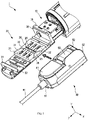
FIG. 1 is a partial perspective view illustrating a configuration of a medical robot of an embodiment of the present disclosure. -
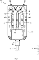
FIG. 2 is a view illustrating a configuration of an arm portion and an adapter inFIG. 1 . -
FIG. 3 is a view illustrating a configuration of a surgical tool inFIG. 1 . -
FIG. 4 is another view illustrating the configuration of the surgical tool inFIG. 1 . -
FIG. 5 is a view illustrating actions of driven portions and projections when attaching the surgical tool to the adapter. -
FIG. 6 is a partial perspective view illustrating detachment of the surgical tool in the medical robot inFIG. 1 . - 1...medical robot, 11...actuator (mover), 20...adapter (attachment portion), 21...attachment surface, 22...transmitter, 23...recessed portion, 24...transmission side hole, 25...guide groove, 26...introducer, 31...first attachment engagement portion (attachment engagement portion), 35...second attachment engagement portion (attachment engagement portion), 40...surgical tool, 41...main body, 42...driven side hole, 43...driven portion, 44...projection, 65...forceps (treatment portion), 51...first surgical tool engagement portion (surgical tool engagement portion), 52...second surgical tool engagement portion (surgical tool engagement portion)
- A description will be given of a medical robot in an embodiment of the present disclosure with reference to
FIG. 1 to FIG. 6 . A medical robot 1 of the present embodiment is a multi-degree-of-freedom manipulator having a multi-degree-of-freedom arm that is remotely controllable, and is used when an operator performs treatment of a patient, such as endoscopic surgery. - As shown in
FIG. 1 , the medical robot 1 comprises adriver 10, anadapter 20, and asurgical tool 40. Theadapter 20 corresponds to one example configuration of an attachment portion. - To simplify the description of the present embodiment, a direction in which the
driver 10 extends is defined as a Z-axis, and a direction toward a leading end of thedriver 10 is defined as a positive direction of the Z-axis. Also, in the description, a direction which is orthogonal to the Z-axis and along which thesurgical tool 40 is relatively moved when being attached to theadapter 20 is defined as an X-axis, and a left direction with respect to a positive direction of the Z-axis is defined as a positive direction of the X-axis. Further, in the description, a direction orthogonal to the Z-axis and the X-axis is defined as a Y-axis and a direction along which thesurgical tool 40 is relatively moved when being detached from theadapter 20 is defined as a positive direction of the Y-axis. - The
driver 10 supports theadapter 20 and thesurgical tool 40 and transmits a driving force to actuate thesurgical tool 40. In the present embodiment, a portion of thedriver 10 where theadapter 20 is arranged is rotatably arranged around an axis extending in the Z-axis direction. - As shown in
FIG. 1 andFIG. 2 , thedriver 10 comprisesactuators 11 and acontroller 12. Theactuator 11 corresponds to one example configuration of a mover. - At least one of the
actuator 11 or thecontroller 12 may be provided in thedriver 10 or may be provided outside thedriver 10, and its arrangement position is not limitative. - The
actuator 11 generates a driving force to actuate thesurgical tool 40. Theactuator 11, which is connected to a later describedtransmitter 22 of theadapter 20 such that the driving force can be transmitted to thetransmitter 22, moves thetransmitter 22 in the positive direction and a negative direction of the Z-axis. - In the present embodiment, the
actuator 11 generates the driving force using a gas, such as air, or a fluid. Theactuator 11 may employ an electric motor, and there is no limitation to a form of generating its power. - Further, the
actuator 11 may be configured with a piston and a cylinder, or may be configured to generate the driving force using another fluid, and there is no limitation to a specific configuration. - The
controller 12 controls generation of the driving force in theactuator 11. Thecontroller 12 also controls movement of thetransmitter 22 in the positive direction and the negative direction of the Z-axis, and controls an arrangement position of thetransmitter 22. In the present embodiment, thecontroller 12 controls supply of a gas, such as air, to theactuator 11. - As shown in
FIG. 1 andFIG. 2 , theadapter 20 is arranged between thedriver 10 and thesurgical tool 40. Theadapter 20 is attachable to and detachable from thedriver 10, and is also attachable to and detachable from thesurgical tool 40. - The
adapter 20 also serves to separate an unclean region on a side of thedriver 10 and a clean region on a side of thesurgical tool 40. Theadapter 20 comprises a not-shown drape that is a film-shaped member to separate the unclean region from the clean region. - The
adapter 20 comprises at least anattachment surface 21, a firstattachment engagement portion 31, and a secondattachment engagement portion 35. The firstattachment engagement portion 31 and the secondattachment engagement portion 35 each correspond to one example configuration of an attachment engagement portion. - The
attachment surface 21 is a surface of theadapter 20 on which thesurgical tool 40 is arranged and which faces a surface, in which driven side holes 42 are formed, of amain body 41 of thesurgical tool 40 described later. The firstattachment engagement portion 31 is provided at an end of theattachment surface 21 in the positive direction of the Z-axis, and the secondattachment engagement portion 35 is provided at an end of theattachment surface 21 in the negative direction of the Z-axis. - The
adapter 20 further comprises at least thetransmitters 22, transmission side holes 24, aguide groove 25, and anintroducer 26. - The
transmitter 22 transmits a driving force to thesurgical tool 40. In the present embodiment, thetransmitter 22 moves within thetransmission side hole 24 in the positive direction and the negative direction of the Z-axis, to thereby transmit the driving force. - The
transmitter 22 comprises a recessedportion 23 configured to engage with a later-describedprojection 44 of thesurgical tool 40. The recessedportion 23 is a recess formed in a surface of thetransmitter 22 to face thesurgical tool 40, in other words, a surface located in the positive direction of the Y-axis. - The recessed
portion 23 has a groove shape extending along the positive direction and the negative direction of the Y-axis. In other words, the recessedportion 23 includes an opening that allows theprojection 44 to enter the recessedportion 23 from the positive direction and come out from the negative direction of the Y-axis. - Side walls of the recessed
portion 23 on a positive direction side and a negative direction side of the Z-axis are shaped to abut theprojection 44. In other words, the side walls are shaped so as to transmit movement of thetransmitter 22 in the positive direction and the negative direction of the Z-axis to theprojection 44. - The
transmission side hole 24 is a through-hole in which thetransmitter 22 is arranged relatively movably, and is configured to allow movement of thetransmitter 22 in a direction along theattachment surface 21, in other words, configured to avoid deviation of thetransmitter 22 from thetransmission side hole 24. Thetransmission side hole 24 is shaped as an elongated hole extending in a direction along the Z-axis. In the present embodiment, three transmission side holes 24 are arranged apart from one another in an X-axis direction. - Although there are three sets of the
transmitters 22 and the transmission side holes 24 in the present embodiment, the number of sets of thetransmitters 22 and the transmission side holes 24 may be greater than three, or may be less than three, and the number is not limited. - The
guide groove 25, which is a recess formed in theattachment surface 21, is a groove to be used for guiding theprojection 44 of a drivenportion 43 described later. Theguide groove 25 extends in a direction of relative movement of thesurgical tool 40 with respect to theattachment surface 21. In the present embodiment, theguide groove 25 extends in a direction intersecting thetransmission side hole 24, for example, in a direction along the X-axis. - The
introducer 26 is a groove formed at each of a first end and a second end of theguide groove 25 so as to be continuous to theguide groove 25, and has a shape with a greater groove width in a direction away from thetransmission side hole 24. It is desirable that a width of an opening portion of theintroducer 26, in other words, a width at both ends thereof in the positive direction and the negative direction of the X-axis is large so as to include at least a moving range of theprojection 44 in thetransmitter 22. Although theintroducer 26 is provided at each of both ends of theguide groove 25 in the present embodiment, theintroducer 26 may be provided only at the first end or the second end of theguide groove 25. - The first
attachment engagement portion 31 is formed at an end of theattachment surface 21 of theadapter 20 in the positive direction of the Z-axis so as to protrude in the positive direction of the Y-axis. The firstattachment engagement portion 31 abuts thesurgical tool 40 arranged on theattachment surface 21, to thereby restrict movement of thesurgical tool 40 in the positive direction of the Z-axis. - The first
attachment engagement portion 31 comprises a surface to face thesurgical tool 40 and the surface comprises afirst engagement groove 32. Thefirst engagement groove 32 is a groove opening in the negative direction of the Z-axis and extending along the X-axis. Thefirst engagement groove 32 engages with a later-described first surgicaltool engagement portion 51 of thesurgical tool 40, to thereby restrict movement of thesurgical tool 40 in directions along the Y-axis. - The second
attachment engagement portion 35 is formed so as to protrude in the positive direction of the Y-axis from the end of theattachment surface 21 of theadapter 20 in the negative direction of the Z-axis. The secondattachment engagement portion 35 abuts thesurgical tool 40 arranged on theattachment surface 21, to thereby restrict movement of thesurgical tool 40 in the negative direction of the Z-axis. - The second
attachment engagement portion 35 comprises a surface to face thesurgical tool 40 and the surface comprises asecond engagement groove 36. Thesecond engagement groove 36 is a groove opening in the positive direction of the Z-axis and extending along the X-axis. Thesecond engagement groove 36 engages with a later-described second surgicaltool engagement portion 52 of thesurgical tool 40, to thereby restrict movement of thesurgical tool 40 in the directions along the Y-axis. - The
surgical tool 40 is used when an operator performs treatment of a patient using the medical robot 1. As shown inFIG. 3 andFIG. 4 , thesurgical tool 40 comprises amain body 41, ashaft 61 extending in a rod shape from themain body 41, and aforceps 65 arranged at an end of theshaft 61 opposite to themain body 41. Theforceps 65 corresponds to one example configuration of a treatment portion. - The
main body 41 is a portion of thesurgical tool 40 configured to be attached to and detached from thedriver 10 and also configured to support theshaft 61. Themain body 41 comprises the driven side holes 42, the drivenportions 43, the first surgicaltool engagement portion 51, the second surgicaltool engagement portions 52, and anoperation portion 55. The first surgicaltool engagement portion 51 and the second surgicaltool engagement portion 52 each correspond to one example configuration of a surgical tool engagement portion. - The driven
side hole 42 is an elongated hole formed in a surface of themain body 41 to face theattachment surface 21 of thedriver 10 and extending in the Z-axis direction. The drivenside hole 42 is provided in a position to face thetransmission side hole 24. The drivenportion 43 to be described later is arranged in the drivenside hole 42 so as to be relatively linearly movable with respect to themain body 41 in the Z-axis direction. In the present embodiment, the three driven side holes 42 are arranged apart from one another in the X-axis direction. - A driving force to move, for example, the
forceps 65 is transmitted from thedriver 10 to the drivenportion 43. The drivenportion 43 is arranged to be linearly movable in the Z-axis direction within the drivenside hole 42 according to the driving force transmitted from a surgical robot. - The driven
portion 43 comprises aprojection 44. Theprojection 44 has a columnar shape projecting from the drivenportion 43 in the negative direction of the Y-axis, and projects further than themain body 41 in the negative direction of the Y-axis when the drivenportion 43 is arranged in the drivenside hole 42. Theprojection 44 engages with the recessedportion 23 provided to thetransmitter 22 in theadapter 20, to thereby transmit a driving force for linear movement in the Z-axis direction. - As shown in
FIG. 4 , the first surgicaltool engagement portion 51 is a protrusion provided at an end of themain body 41 in the positive direction of the Z-axis. The first surgicaltool engagement portion 51 engages with thefirst engagement groove 32 of the firstattachment engagement portion 31, to thereby restrict movement of thesurgical tool 40 in the directions along the Y-axis. - As shown in
FIG. 3 andFIG. 4 , the second surgicaltool engagement portions 52 are two protrusions provided at an end of themain body 41 in the negative direction of the Z-axis. The second surgicaltool engagement portions 52 engage with thesecond engagement groove 36 of the secondattachment engagement portion 35, to thereby restrict movement of thesurgical tool 40 in the directions along the Y-axis. - The
operation portion 55 is a portion to be used when causing the second surgicaltool engagement portions 52 to be housed in themain body 41 and to protrude from themain body 41. Theoperation portion 55 is provided on a surface of themain body 41 on a positive direction side of the Y-axis and in an area on a negative direction side of the Z-axis. - The
operation portion 55 is arranged to be relatively movable along the Z-axis with respect to themain body 41. For example, when theoperation portion 55 is relatively moved in the positive direction of the Z-axis with respect to themain body 41, the second surgicaltool engagement portions 52 are housed in themain body 41. Conversely, when theoperation portion 55 is moved in the negative direction of the Z-axis with respect to themain body 41, the second surgicaltool engagement portions 52 protrude from themain body 41. - As shown in
FIG. 3 andFIG. 4 , theshaft 61 is a tubular shaped member arranged to extend from themain body 41 in the Z-axis direction. Theforceps 65 is arranged at the end of theshaft 61 in the positive direction of the Z-axis. Also, a joint 62 is provided to theshaft 61 in a vicinity of theforceps 65. - The joint 62 is configured to allow changes in orientation of the
forceps 65 and configured to be rotatable about the X-axis direction as a rotation axis and about the Y-axis direction as a rotation axis. The joint 62 is configured, for example, so as to be rotated by the driving force transmitted by thepower transmitter 22. It is to be noted that there is no particular limitation to the configuration of the joint 62. - The
forceps 65 is arranged at the end of theshaft 61 in the positive direction of the Z-axis, and is configured to be opened and closed by a driving force transmitted from the drivenportion 43 through a wire or the like. There is no particular limitation to the configuration to open and close theforceps 65. - Next, a description will be given of attachment and detachment of the
surgical tool 40 in the medical robot 1 configured as above with reference toFIG. 1 ,FIG. 2 ,FIG. 5 , andFIG. 6 . A case of attaching thesurgical tool 40 to theadapter 20 will be first described, and then a case of detaching thesurgical tool 40 from theadapter 20 will be described. - When attaching the
surgical tool 40 to theadapter 20, thecontroller 12 performs control to drive theactuators 11 such that thetransmitters 22 are arranged at specified positions, as shown inFIG. 2 . Once thetransmitters 22 are arranged at specified positions, the recessedportions 23 of thetransmitters 22 and theguide groove 25 form a groove extending in the direction along the X-axis. - The specified positions here mean positions where the recessed
portions 23 of thetransmitters 22 are arranged at positions at which theguide groove 25 and the transmission side holes 24 intersect. In other words, the drivenportions 43 engage with thetransmitters 22 at the specified position in response to attachment of thesurgical tool 40 and theadapter 20. Specifically, arrangement positions of thetransmitters 22 shown inFIG. 2 are specified positions. - Thereafter, as shown in
FIG. 1 , thesurgical tool 40 is moved in the direction along the X-axis to be closer to theadapter 20, and attachment is performed.FIG. 1 shows an example of attachment by moving thesurgical tool 40 from the positive side to the negative side of the X-axis. Attachment may be performed by moving thesurgical tool 40 closer to theadapter 20 from the negative side to the positive side of the X-axis. - During attachment, the first surgical
tool engagement portion 51 of thesurgical tool 40 moves in the direction along the X-axis into engagement with thefirst engagement groove 32 of theadapter 20. Also, the second surgicaltool engagement portions 52 move in the direction along the X-axis into engagement with thesecond engagement groove 36 of theadapter 20. - Further, as shown in
FIG. 5 , the drivenportions 43 of thesurgical tool 40 are guided by theguide groove 25 and theintroducer 26 to positions allowing transmission of a driving force with thetransmitter 22. A description will be given of an example case where the drivenportions 43 are arranged apart from theguide groove 25 on the positive direction side or the negative direction side of the Z-axis. - When the
surgical tool 40 approaches theadapter 20 along the X-axis, theprojections 44 of the drivenportions 43 each abuts an oblique surface of theintroducer 26. When thesurgical tool 40 is further moved, theprojections 44 move toward theguide groove 25 along the oblique surface of theintroducer 26, and enter the groove formed by theguide groove 25 and the recessedportions 23. - When the
surgical tool 40 moves to a previously specified position relative to theadapter 20, theprojections 44 are arranged in the recessedportions 23. In other words, theprojections 44 are arranged in positions indicated by dotted lines inFIG. 5 . As a result, thetransmitters 22 and the drivenportions 43 are engaged to allow transmission of driving forces, and attachment between thesurgical tool 40 and theadapter 20 is completed. - In the case of detaching the
surgical tool 40 from theadapter 20, an operation is first performed of sliding theoperation portion 55 of thesurgical tool 40 in the positive direction of the Z-axis, as shown inFIG. 3 . By this operation, the second surgicaltool engagement portions 52 are housed in themain body 41. As a result of this operation, engagement between the second surgicaltool engagement portions 52 and thesecond engagement groove 36 is released, as shown inFIG. 6 . - Then, as shown in
FIG. 6 , an end of thesurgical tool 40 on the negative direction side of the Z-axis is raised in a direction of departing from theadapter 20, specifically in the positive direction of the Y-axis. Subsequently, thesurgical tool 40 as a whole is raised in the positive direction of the Y-axis, and the first surgicaltool engagement portion 51 is pulled out from thefirst engagement groove 32. As a result, detachment of thesurgical tool 40 from theadapter 20 is completed. - According to the medical robot 1 and the
adapter 20 configured as described above, thesurgical tool 40 can be attached to theadapter 20 by relative movement between thesurgical tool 40 and theadapter 20 in a direction along theattachment surface 21 and intersecting a linear motion direction of the drivenportions 43 and thetransmitters 22. Also, the drivenportions 43 are guided to the specified positions in the transmission side holes 24 when attaching thesurgical tool 40 to theadapter 20. - In comparison with, for example, the configuration disclosed in Patent Document 1, the
transmitter 22 and the drivenportion 43 can be engaged with each other by a simple configuration since it is unnecessary to use a biasing mechanism. Also, there is less need to provide a gap between thetransmitter 22 and the drivenportion 43, thus facilitating secure engagement therebetween. - Further, since the gap can be reduced, increase in operability of the medical robot 1 is facilitated. Moreover, reduction of the gap facilitates transmission of an external force, which is a force applied to the
forceps 65 of thesurgical tool 40, to the medical robot 1, and facilitates increase in accuracy when estimating the external force. For example, it is possible to facilitate increase in safety of surgeries using the medical robot 1, and to facilitate reducing occurrence of complications. In other words, it is possible to facilitate improved QOL of patients, and to facilitate reducing burden on doctors who operate the medical robot 1. "QOL", referred to herein, is an abbreviation of "Quality of Life". Moreover, it is possible to facilitate achievement of an improved learning curve in surgeries using the medical robot 1. - In addition, it is possible to determine whether arrangement relationships of the
transmitters 22 and the drivenportions 43 are each a desired arrangement relationship based on a relative position of thesurgical tool 40 and theadapter 20. Examples of the desired arrangement relationship may include an arrangement relationship that allows transmission of a driving force. In other words, there is less need to use a detection device, such as a sensor and a switch, than in the configuration disclosed in Patent Document 1. Accordingly, it is possible to reduce complication of the configuration caused by providing the detection device, and to facilitate downsizing of the medical robot 1. - By providing the
introducer 26 to theguide groove 25, theprojection 44 of the drivenportion 43 is guided by theintroducer 26 and thus is facilitated to enter theguide groove 25 when attaching thesurgical tool 40 to theadapter 20. Also, in a case where theintroducer 26 is provided at each of both ends of theguide groove 25, as compared with a case of being provided at one end, there is an increased degree of freedom in terms of an approaching direction of thesurgical tool 40 to theadapter 20, and thus attachment of thesurgical tool 40 is facilitated. - By providing the
actuators 11, thetransmitters 22 can be easily arranged at the specified positions when attaching thesurgical tool 40 to theadapter 20. As compared with a case without theactuators 11, workload can be reduced when attaching thesurgical tool 40 to theadapter 20, and thus attachment is facilitated. - By providing the transmission side holes 24 and the
transmitters 22 side by side along a relative movement direction of thesurgical tool 40 and theadapter 20, and providing the driven side holes 42 and the drivenportions 43 so as to correspond to at least a part of the transmission side holes 24 and thetransmitters 22, it is possible to transmit different driving forces to theforceps 65 using a plurality of combinations of thetransmitters 22 and the drivenportions 43. Accordingly, it is possible to control a plurality of actions of theforceps 65. - By providing the recessed
portion 23 to thetransmitter 22, it is possible to engage theprojection 44 of the drivenportion 43 with the recessedportion 23 of thetransmitter 22 when thesurgical tool 40 is attached to theadapter 20. Also, it is possible to transmit a driving force from thetransmitter 22 to the drivenportion 43 based on the engagement of theprojection 44 with the recessedportion 23. - It is to be noted that the technical scope of the present disclosure is not limited to the aforementioned embodiment, and various modifications may be made without departing from the subject matter of the present disclosure. For example, although the aforementioned embodiment is described employing a configuration where the
surgical tool 40 may be attached from the positive direction side of the X-axis or may be attached from the negative direction side of the X-axis, it may be possible to employ a configuration where thesurgical tool 40 is attachable only from the positive direction side of the X-axis, or only from the negative direction side of the X-axis. - Also, although the
transmitter 22 is moved to the specified position using theactuator 11 in the present embodiment, a biasing member, such as a spring, may be used in place of theactuator 11 when moving thetransmitter 22 to the specified position. - Further, although the
driver 10 and theadapter 20 are attachable to and detachable from each other in the present embodiment, a component equivalent to theadapter 20 may be integrated with thedriver 10, and there is no particular limitation therefor.
Claims (6)
- A medical robot comprising:a surgical tool at least comprising:
a main body comprising:a driven portion configured to transmit a driving force to a treatment portion for performing a medical treatment; anda driven side hole in which the driven portion is housed and the driven portion is arranged so as to be relatively linearly movable; andan attachment portion at least comprising:an attachment surface configured to face a surface of the main body in which the driven side hole is provided; anda transmission side hole in which a transmitter to transmit a driving force in a linear motion direction to the driven portion is arranged,wherein the surgical tool and the attachment portion respectively comprise a surgical tool engagement portion and an attachment engagement portion configured to attach the surgical tool to the attachment portion by relative movement of the surgical tool and the attachment portion in a direction along the attachment surface and intersecting the linear motion direction, andwherein the attachment surface comprises a guide groove extending in a direction in which the surgical tool relatively moves with respect to the attachment portion and configured to engage with a projection projecting from the driven portion when attaching the surgical tool to the attachment portion, thereby guiding the driven portion to a specified position of the transmission side hole. - The medical robot according to claim 1, further comprising an introducer provided at least at one end of the guide groove along a relative movement direction of the surgical tool and the attachment portion, the introducer having a greater groove width in a direction away from the transmission side hole.
- The medical robot according to claim 1, further comprising a mover configured to move the transmitter to the specified position.
- The medical robot according to claim 1,wherein a plurality of the transmission side holes and a plurality of the transmitters are provided in the attachment portion side by side along the relative movement direction of the surgical tool and the attachment portion, andwherein a plurality of the driven side holes and a plurality of the driven portions are provided in the main body so as to correspond to at least a part of the plurality of the transmission side holes and the plurality of the transmitters.
- The medical robot according to claim 1,wherein the transmitter comprises a recessed portion configured to engage with the projection of the driven portion in response to attachment of the surgical tool to the attachment portion, the recessed portion including an opening that allows the projection to move along the relative movement direction of the surgical tool and the attachment portion.
- An attachment portion of a medical robot, to which a surgical tool is attached, the surgical tool at least comprising a main body that comprises a driven portion configured to transmit a driving force to a treatment portion for performing a medical treatment; and a driven side hole in which the driven portion is housed and the driven portion is arranged so as to be relatively linearly movable,
the attachment portion at least comprising:an attachment surface configured to face a surface of the main body in which the driven side hole is provided;a transmission side hole in which a transmitter to transmit a driving force in a linear motion direction to the driven portion is arranged;an attachment engagement portion configured to attach the surgical tool to the attachment portion by relative movement of the surgical tool and the attachment portion in a direction along the attachment surface and intersecting the linear motion direction; anda guide groove provided in the attachment surface and extending in a direction in which the surgical tool relatively moves with respect to the attachment portion, and configured to engage with a projection projecting from the driven portion when attaching the surgical tool to the attachment portion, thereby guiding the driven portion to a specified position of the transmission side hole.
Applications Claiming Priority (2)
| Application Number | Priority Date | Filing Date | Title |
|---|---|---|---|
| JP2019230907A JP6762592B1 (en) | 2019-12-20 | 2019-12-20 | Medical robots and mounting parts for medical robots |
| PCT/JP2020/035758 WO2021124631A1 (en) | 2019-12-20 | 2020-09-23 | Medical robot and mounting part of medical robot |
Publications (3)
| Publication Number | Publication Date |
|---|---|
| EP4079248A1 true EP4079248A1 (en) | 2022-10-26 |
| EP4079248A4 EP4079248A4 (en) | 2023-11-08 |
| EP4079248B1 EP4079248B1 (en) | 2025-05-07 |
Family
ID=72614600
Family Applications (1)
| Application Number | Title | Priority Date | Filing Date |
|---|---|---|---|
| EP20901910.8A Active EP4079248B1 (en) | 2019-12-20 | 2020-09-23 | Medical robot and mounting part of medical robot |
Country Status (4)
| Country | Link |
|---|---|
| EP (1) | EP4079248B1 (en) |
| JP (1) | JP6762592B1 (en) |
| CN (1) | CN114828771B (en) |
| WO (1) | WO2021124631A1 (en) |
Families Citing this family (2)
| Publication number | Priority date | Publication date | Assignee | Title |
|---|---|---|---|---|
| CN118662236B (en) * | 2023-03-17 | 2025-09-16 | 北京术锐机器人股份有限公司 | Compact surgical tool and surgical robot system |
| CN118680607B (en) * | 2023-03-24 | 2025-09-16 | 北京术锐机器人股份有限公司 | Compact snake bone surgical tool and surgical robot system |
Family Cites Families (14)
| Publication number | Priority date | Publication date | Assignee | Title |
|---|---|---|---|---|
| JP3419543B2 (en) * | 1994-04-22 | 2003-06-23 | エヌオーケー株式会社 | Parallel opening and closing chuck device |
| US7666191B2 (en) | 1996-12-12 | 2010-02-23 | Intuitive Surgical, Inc. | Robotic surgical system with sterile surgical adaptor |
| KR101750518B1 (en) * | 2010-02-19 | 2017-06-26 | (주)미래컴퍼니 | Connection structure of wheel and surgical instrument |
| CN104706426A (en) * | 2009-09-23 | 2015-06-17 | 伊顿株式会社 | Sterile adapter, connection structure of wheel and connection structure of surgical instrument |
| JP5800676B2 (en) * | 2011-10-25 | 2015-10-28 | オリンパス株式会社 | Medical manipulator |
| US10046465B2 (en) * | 2013-06-06 | 2018-08-14 | Seiko Epson Corporation | Attaching and detaching device and robot |
| JP6674377B2 (en) * | 2013-08-15 | 2020-04-01 | インテュイティブ サージカル オペレーションズ, インコーポレイテッド | Apparatus with proximal and distal driven discs |
| DE102014205036A1 (en) * | 2014-03-18 | 2015-09-24 | Richard Wolf Gmbh | Endoscopic instrument for connection to a surgical robot |
| CA2968609C (en) * | 2014-12-11 | 2017-09-26 | Titan Medical Inc. | Actuator and drive for manipulating a tool |
| JP6353796B2 (en) * | 2015-02-27 | 2018-07-04 | 株式会社コスメック | Output device and output system |
| GB2552540B (en) * | 2016-07-29 | 2021-11-24 | Cmr Surgical Ltd | Interface structure |
| GB201615616D0 (en) * | 2016-09-14 | 2016-10-26 | Cambridge Medical Robotics Ltd | Interfacing a surgical robotic arm and instrument |
| CN113349932A (en) * | 2016-12-20 | 2021-09-07 | 威博外科公司 | Sterile adapter control system and communication interface for robotic surgical system |
| JP6631974B2 (en) * | 2017-05-16 | 2020-01-15 | リバーフィールド株式会社 | Power transmission adapter and medical manipulator system |
-
2019
- 2019-12-20 JP JP2019230907A patent/JP6762592B1/en active Active
-
2020
- 2020-09-23 EP EP20901910.8A patent/EP4079248B1/en active Active
- 2020-09-23 CN CN202080088604.XA patent/CN114828771B/en active Active
- 2020-09-23 WO PCT/JP2020/035758 patent/WO2021124631A1/en not_active Ceased
Also Published As
| Publication number | Publication date |
|---|---|
| CN114828771B (en) | 2025-12-19 |
| WO2021124631A1 (en) | 2021-06-24 |
| CN114828771A (en) | 2022-07-29 |
| US20220313376A1 (en) | 2022-10-06 |
| JP6762592B1 (en) | 2020-09-30 |
| EP4079248A4 (en) | 2023-11-08 |
| JP2021097856A (en) | 2021-07-01 |
| EP4079248B1 (en) | 2025-05-07 |
Similar Documents
| Publication | Publication Date | Title |
|---|---|---|
| US20250010470A1 (en) | Guided tool change | |
| CN109414297B (en) | Instrument carrier for manipulators of robotic surgical systems | |
| US11198226B2 (en) | Surgical robot | |
| US9788847B2 (en) | Medical manipulator | |
| US8306656B1 (en) | Method and system for performing medical procedure | |
| US10076348B2 (en) | Rotary input for lever actuation | |
| KR20230058117A (en) | Control of Surgical Instruments with Backlash, Friction, and Compliance Under External Load in a Surgical Robotic System | |
| EP3788994B1 (en) | Intraocular surgery instrument holder | |
| KR102300156B1 (en) | A locking mechanism to secure a sterile adapter assembly to an actuator assembly for a robotic surgical system | |
| US20180214220A1 (en) | Surgical robot | |
| WO2012164517A1 (en) | Robotic platform for mini-invasive surgery | |
| EP4079248B1 (en) | Medical robot and mounting part of medical robot | |
| JP6979252B1 (en) | Floating drive mechanism for medical robots and medical robots | |
| EP3871629B1 (en) | Wearable surgical robot arm | |
| US12616532B2 (en) | Medical robot and attachment portion of medical robot | |
| CN111358562A (en) | A surgical instrument control method for a laparoscopic surgical robot | |
| Eugster et al. | A parallel robotic mechanism for the stabilization and guidance of an endoscope tip in laser osteotomy | |
| US12558176B2 (en) | Controlled resistance in backdrivable joints | |
| JP6867665B1 (en) | Medical robots, surgical tools and mounting parts | |
| JP6791516B1 (en) | Surgical robot surgical tools | |
| CN111358559A (en) | A surgical instrument control method for a laparoscopic surgical robot | |
| CN114098996A (en) | Instrument driving device, instrument arm, slave hand end and robot-assisted surgery system | |
| CN114098995A (en) | Instrument driving device, instrument arm, slave hand end and robot-assisted surgery system |
Legal Events
| Date | Code | Title | Description |
|---|---|---|---|
| STAA | Information on the status of an ep patent application or granted ep patent |
Free format text: STATUS: THE INTERNATIONAL PUBLICATION HAS BEEN MADE |
|
| PUAI | Public reference made under article 153(3) epc to a published international application that has entered the european phase |
Free format text: ORIGINAL CODE: 0009012 |
|
| STAA | Information on the status of an ep patent application or granted ep patent |
Free format text: STATUS: REQUEST FOR EXAMINATION WAS MADE |
|
| 17P | Request for examination filed |
Effective date: 20220715 |
|
| AK | Designated contracting states |
Kind code of ref document: A1 Designated state(s): AL AT BE BG CH CY CZ DE DK EE ES FI FR GB GR HR HU IE IS IT LI LT LU LV MC MK MT NL NO PL PT RO RS SE SI SK SM TR |
|
| DAV | Request for validation of the european patent (deleted) | ||
| DAX | Request for extension of the european patent (deleted) | ||
| RAP3 | Party data changed (applicant data changed or rights of an application transferred) |
Owner name: RIVERFIELD INC. |
|
| RAP3 | Party data changed (applicant data changed or rights of an application transferred) |
Owner name: RIVERFIELD INC. |
|
| A4 | Supplementary search report drawn up and despatched |
Effective date: 20231011 |
|
| RIC1 | Information provided on ipc code assigned before grant |
Ipc: A61B 17/00 20060101ALI20231005BHEP Ipc: A61B 34/30 20160101AFI20231005BHEP |
|
| STAA | Information on the status of an ep patent application or granted ep patent |
Free format text: STATUS: EXAMINATION IS IN PROGRESS |
|
| GRAP | Despatch of communication of intention to grant a patent |
Free format text: ORIGINAL CODE: EPIDOSNIGR1 |
|
| STAA | Information on the status of an ep patent application or granted ep patent |
Free format text: STATUS: GRANT OF PATENT IS INTENDED |
|
| INTG | Intention to grant announced |
Effective date: 20241203 |
|
| GRAS | Grant fee paid |
Free format text: ORIGINAL CODE: EPIDOSNIGR3 |
|
| GRAA | (expected) grant |
Free format text: ORIGINAL CODE: 0009210 |
|
| STAA | Information on the status of an ep patent application or granted ep patent |
Free format text: STATUS: THE PATENT HAS BEEN GRANTED |
|
| AK | Designated contracting states |
Kind code of ref document: B1 Designated state(s): AL AT BE BG CH CY CZ DE DK EE ES FI FR GB GR HR HU IE IS IT LI LT LU LV MC MK MT NL NO PL PT RO RS SE SI SK SM TR |
|
| REG | Reference to a national code |
Ref country code: GB Ref legal event code: FG4D |
|
| REG | Reference to a national code |
Ref country code: CH Ref legal event code: EP |
|
| REG | Reference to a national code |
Ref country code: DE Ref legal event code: R096 Ref document number: 602020051085 Country of ref document: DE |
|
| REG | Reference to a national code |
Ref country code: IE Ref legal event code: FG4D |
|
| P01 | Opt-out of the competence of the unified patent court (upc) registered |
Free format text: CASE NUMBER: APP_21227/2025 Effective date: 20250505 |
|
| REG | Reference to a national code |
Ref country code: NL Ref legal event code: MP Effective date: 20250507 |
|
| PG25 | Lapsed in a contracting state [announced via postgrant information from national office to epo] |
Ref country code: FI Free format text: LAPSE BECAUSE OF FAILURE TO SUBMIT A TRANSLATION OF THE DESCRIPTION OR TO PAY THE FEE WITHIN THE PRESCRIBED TIME-LIMIT Effective date: 20250507 Ref country code: ES Free format text: LAPSE BECAUSE OF FAILURE TO SUBMIT A TRANSLATION OF THE DESCRIPTION OR TO PAY THE FEE WITHIN THE PRESCRIBED TIME-LIMIT Effective date: 20250507 Ref country code: PT Free format text: LAPSE BECAUSE OF FAILURE TO SUBMIT A TRANSLATION OF THE DESCRIPTION OR TO PAY THE FEE WITHIN THE PRESCRIBED TIME-LIMIT Effective date: 20250908 |
|
| PGFP | Annual fee paid to national office [announced via postgrant information from national office to epo] |
Ref country code: DE Payment date: 20250829 Year of fee payment: 6 |
|
| REG | Reference to a national code |
Ref country code: LT Ref legal event code: MG9D |
|
| PG25 | Lapsed in a contracting state [announced via postgrant information from national office to epo] |
Ref country code: NO Free format text: LAPSE BECAUSE OF FAILURE TO SUBMIT A TRANSLATION OF THE DESCRIPTION OR TO PAY THE FEE WITHIN THE PRESCRIBED TIME-LIMIT Effective date: 20250807 Ref country code: GR Free format text: LAPSE BECAUSE OF FAILURE TO SUBMIT A TRANSLATION OF THE DESCRIPTION OR TO PAY THE FEE WITHIN THE PRESCRIBED TIME-LIMIT Effective date: 20250808 |
|
| PG25 | Lapsed in a contracting state [announced via postgrant information from national office to epo] |
Ref country code: PL Free format text: LAPSE BECAUSE OF FAILURE TO SUBMIT A TRANSLATION OF THE DESCRIPTION OR TO PAY THE FEE WITHIN THE PRESCRIBED TIME-LIMIT Effective date: 20250507 Ref country code: NL Free format text: LAPSE BECAUSE OF FAILURE TO SUBMIT A TRANSLATION OF THE DESCRIPTION OR TO PAY THE FEE WITHIN THE PRESCRIBED TIME-LIMIT Effective date: 20250507 |
|
| REG | Reference to a national code |
Ref country code: AT Ref legal event code: MK05 Ref document number: 1791614 Country of ref document: AT Kind code of ref document: T Effective date: 20250507 |
|
| PG25 | Lapsed in a contracting state [announced via postgrant information from national office to epo] |
Ref country code: BG Free format text: LAPSE BECAUSE OF FAILURE TO SUBMIT A TRANSLATION OF THE DESCRIPTION OR TO PAY THE FEE WITHIN THE PRESCRIBED TIME-LIMIT Effective date: 20250507 |
|
| PGFP | Annual fee paid to national office [announced via postgrant information from national office to epo] |
Ref country code: GB Payment date: 20250923 Year of fee payment: 6 |
|
| PG25 | Lapsed in a contracting state [announced via postgrant information from national office to epo] |
Ref country code: HR Free format text: LAPSE BECAUSE OF FAILURE TO SUBMIT A TRANSLATION OF THE DESCRIPTION OR TO PAY THE FEE WITHIN THE PRESCRIBED TIME-LIMIT Effective date: 20250507 |
|
| PG25 | Lapsed in a contracting state [announced via postgrant information from national office to epo] |
Ref country code: AT Free format text: LAPSE BECAUSE OF FAILURE TO SUBMIT A TRANSLATION OF THE DESCRIPTION OR TO PAY THE FEE WITHIN THE PRESCRIBED TIME-LIMIT Effective date: 20250507 |
|
| PGFP | Annual fee paid to national office [announced via postgrant information from national office to epo] |
Ref country code: FR Payment date: 20250924 Year of fee payment: 6 |
|
| PG25 | Lapsed in a contracting state [announced via postgrant information from national office to epo] |
Ref country code: RS Free format text: LAPSE BECAUSE OF FAILURE TO SUBMIT A TRANSLATION OF THE DESCRIPTION OR TO PAY THE FEE WITHIN THE PRESCRIBED TIME-LIMIT Effective date: 20250807 |
|
| PG25 | Lapsed in a contracting state [announced via postgrant information from national office to epo] |
Ref country code: IS Free format text: LAPSE BECAUSE OF FAILURE TO SUBMIT A TRANSLATION OF THE DESCRIPTION OR TO PAY THE FEE WITHIN THE PRESCRIBED TIME-LIMIT Effective date: 20250907 |
|
| PG25 | Lapsed in a contracting state [announced via postgrant information from national office to epo] |
Ref country code: LV Free format text: LAPSE BECAUSE OF FAILURE TO SUBMIT A TRANSLATION OF THE DESCRIPTION OR TO PAY THE FEE WITHIN THE PRESCRIBED TIME-LIMIT Effective date: 20250507 |
|
| PG25 | Lapsed in a contracting state [announced via postgrant information from national office to epo] |
Ref country code: DK Free format text: LAPSE BECAUSE OF FAILURE TO SUBMIT A TRANSLATION OF THE DESCRIPTION OR TO PAY THE FEE WITHIN THE PRESCRIBED TIME-LIMIT Effective date: 20250507 Ref country code: SM Free format text: LAPSE BECAUSE OF FAILURE TO SUBMIT A TRANSLATION OF THE DESCRIPTION OR TO PAY THE FEE WITHIN THE PRESCRIBED TIME-LIMIT Effective date: 20250507 |
|
| PG25 | Lapsed in a contracting state [announced via postgrant information from national office to epo] |
Ref country code: CZ Free format text: LAPSE BECAUSE OF FAILURE TO SUBMIT A TRANSLATION OF THE DESCRIPTION OR TO PAY THE FEE WITHIN THE PRESCRIBED TIME-LIMIT Effective date: 20250507 |
|
| PG25 | Lapsed in a contracting state [announced via postgrant information from national office to epo] |
Ref country code: EE Free format text: LAPSE BECAUSE OF FAILURE TO SUBMIT A TRANSLATION OF THE DESCRIPTION OR TO PAY THE FEE WITHIN THE PRESCRIBED TIME-LIMIT Effective date: 20250507 |
|
| PG25 | Lapsed in a contracting state [announced via postgrant information from national office to epo] |
Ref country code: SK Free format text: LAPSE BECAUSE OF FAILURE TO SUBMIT A TRANSLATION OF THE DESCRIPTION OR TO PAY THE FEE WITHIN THE PRESCRIBED TIME-LIMIT Effective date: 20250507 |
|
| PG25 | Lapsed in a contracting state [announced via postgrant information from national office to epo] |
Ref country code: IT Free format text: LAPSE BECAUSE OF FAILURE TO SUBMIT A TRANSLATION OF THE DESCRIPTION OR TO PAY THE FEE WITHIN THE PRESCRIBED TIME-LIMIT Effective date: 20250507 |
|
| PG25 | Lapsed in a contracting state [announced via postgrant information from national office to epo] |
Ref country code: RO Free format text: LAPSE BECAUSE OF FAILURE TO SUBMIT A TRANSLATION OF THE DESCRIPTION OR TO PAY THE FEE WITHIN THE PRESCRIBED TIME-LIMIT Effective date: 20250507 |
|
| REG | Reference to a national code |
Ref country code: DE Ref legal event code: R097 Ref document number: 602020051085 Country of ref document: DE |
|
| PLBE | No opposition filed within time limit |
Free format text: ORIGINAL CODE: 0009261 |
|
| STAA | Information on the status of an ep patent application or granted ep patent |
Free format text: STATUS: NO OPPOSITION FILED WITHIN TIME LIMIT |
|
| REG | Reference to a national code |
Ref country code: CH Ref legal event code: L10 Free format text: ST27 STATUS EVENT CODE: U-0-0-L10-L00 (AS PROVIDED BY THE NATIONAL OFFICE) Effective date: 20260318 |
|
| 26N | No opposition filed |
Effective date: 20260210 |