EP4079239B1 - Thrombektomievorrichtung - Google Patents
Thrombektomievorrichtung Download PDFInfo
- Publication number
- EP4079239B1 EP4079239B1 EP21169975.6A EP21169975A EP4079239B1 EP 4079239 B1 EP4079239 B1 EP 4079239B1 EP 21169975 A EP21169975 A EP 21169975A EP 4079239 B1 EP4079239 B1 EP 4079239B1
- Authority
- EP
- European Patent Office
- Prior art keywords
- control arm
- extraction
- distal
- helical coil
- proximal
- Prior art date
- Legal status (The legal status is an assumption and is not a legal conclusion. Google has not performed a legal analysis and makes no representation as to the accuracy of the status listed.)
- Active
Links
Images


Classifications
-
- A—HUMAN NECESSITIES
- A61—MEDICAL OR VETERINARY SCIENCE; HYGIENE
- A61B—DIAGNOSIS; SURGERY; IDENTIFICATION
- A61B17/00—Surgical instruments, devices or methods
- A61B17/22—Implements for squeezing-off ulcers or the like on inner organs of the body; Implements for scraping-out cavities of body organs, e.g. bones; for invasive removal or destruction of calculus using mechanical vibrations; for removing obstructions in blood vessels, not otherwise provided for
- A61B17/221—Gripping devices in the form of loops or baskets for gripping calculi or similar types of obstructions
-
- A—HUMAN NECESSITIES
- A61—MEDICAL OR VETERINARY SCIENCE; HYGIENE
- A61B—DIAGNOSIS; SURGERY; IDENTIFICATION
- A61B17/00—Surgical instruments, devices or methods
- A61B17/32—Surgical cutting instruments
- A61B17/3205—Excision instruments
- A61B17/3207—Atherectomy devices working by cutting or abrading; Similar devices specially adapted for non-vascular obstructions
- A61B17/320725—Atherectomy devices working by cutting or abrading; Similar devices specially adapted for non-vascular obstructions with radially expandable cutting or abrading elements
-
- A—HUMAN NECESSITIES
- A61—MEDICAL OR VETERINARY SCIENCE; HYGIENE
- A61B—DIAGNOSIS; SURGERY; IDENTIFICATION
- A61B17/00—Surgical instruments, devices or methods
- A61B17/32—Surgical cutting instruments
- A61B17/3205—Excision instruments
- A61B17/3207—Atherectomy devices working by cutting or abrading; Similar devices specially adapted for non-vascular obstructions
- A61B17/320758—Atherectomy devices working by cutting or abrading; Similar devices specially adapted for non-vascular obstructions with a rotating cutting instrument, e.g. motor driven
-
- A—HUMAN NECESSITIES
- A61—MEDICAL OR VETERINARY SCIENCE; HYGIENE
- A61B—DIAGNOSIS; SURGERY; IDENTIFICATION
- A61B17/00—Surgical instruments, devices or methods
- A61B17/32—Surgical cutting instruments
- A61B17/3205—Excision instruments
- A61B17/3207—Atherectomy devices working by cutting or abrading; Similar devices specially adapted for non-vascular obstructions
- A61B17/320783—Atherectomy devices working by cutting or abrading; Similar devices specially adapted for non-vascular obstructions through side-hole, e.g. sliding or rotating cutter inside catheter
-
- A—HUMAN NECESSITIES
- A61—MEDICAL OR VETERINARY SCIENCE; HYGIENE
- A61B—DIAGNOSIS; SURGERY; IDENTIFICATION
- A61B17/00—Surgical instruments, devices or methods
- A61B2017/00681—Aspects not otherwise provided for
- A61B2017/00685—Archimedes screw
-
- A—HUMAN NECESSITIES
- A61—MEDICAL OR VETERINARY SCIENCE; HYGIENE
- A61B—DIAGNOSIS; SURGERY; IDENTIFICATION
- A61B17/00—Surgical instruments, devices or methods
- A61B17/22—Implements for squeezing-off ulcers or the like on inner organs of the body; Implements for scraping-out cavities of body organs, e.g. bones; for invasive removal or destruction of calculus using mechanical vibrations; for removing obstructions in blood vessels, not otherwise provided for
- A61B2017/22038—Implements for squeezing-off ulcers or the like on inner organs of the body; Implements for scraping-out cavities of body organs, e.g. bones; for invasive removal or destruction of calculus using mechanical vibrations; for removing obstructions in blood vessels, not otherwise provided for with a guide wire
-
- A—HUMAN NECESSITIES
- A61—MEDICAL OR VETERINARY SCIENCE; HYGIENE
- A61B—DIAGNOSIS; SURGERY; IDENTIFICATION
- A61B17/00—Surgical instruments, devices or methods
- A61B17/22—Implements for squeezing-off ulcers or the like on inner organs of the body; Implements for scraping-out cavities of body organs, e.g. bones; for invasive removal or destruction of calculus using mechanical vibrations; for removing obstructions in blood vessels, not otherwise provided for
- A61B2017/22079—Implements for squeezing-off ulcers or the like on inner organs of the body; Implements for scraping-out cavities of body organs, e.g. bones; for invasive removal or destruction of calculus using mechanical vibrations; for removing obstructions in blood vessels, not otherwise provided for with suction of debris
-
- A—HUMAN NECESSITIES
- A61—MEDICAL OR VETERINARY SCIENCE; HYGIENE
- A61B—DIAGNOSIS; SURGERY; IDENTIFICATION
- A61B17/00—Surgical instruments, devices or methods
- A61B17/22—Implements for squeezing-off ulcers or the like on inner organs of the body; Implements for scraping-out cavities of body organs, e.g. bones; for invasive removal or destruction of calculus using mechanical vibrations; for removing obstructions in blood vessels, not otherwise provided for
- A61B17/221—Gripping devices in the form of loops or baskets for gripping calculi or similar types of obstructions
- A61B2017/2212—Gripping devices in the form of loops or baskets for gripping calculi or similar types of obstructions having a closed distal end, e.g. a loop
-
- A—HUMAN NECESSITIES
- A61—MEDICAL OR VETERINARY SCIENCE; HYGIENE
- A61B—DIAGNOSIS; SURGERY; IDENTIFICATION
- A61B17/00—Surgical instruments, devices or methods
- A61B17/22—Implements for squeezing-off ulcers or the like on inner organs of the body; Implements for scraping-out cavities of body organs, e.g. bones; for invasive removal or destruction of calculus using mechanical vibrations; for removing obstructions in blood vessels, not otherwise provided for
- A61B17/221—Gripping devices in the form of loops or baskets for gripping calculi or similar types of obstructions
- A61B2017/2215—Gripping devices in the form of loops or baskets for gripping calculi or similar types of obstructions having an open distal end
-
- A—HUMAN NECESSITIES
- A61—MEDICAL OR VETERINARY SCIENCE; HYGIENE
- A61B—DIAGNOSIS; SURGERY; IDENTIFICATION
- A61B17/00—Surgical instruments, devices or methods
- A61B17/32—Surgical cutting instruments
- A61B17/3205—Excision instruments
- A61B17/3207—Atherectomy devices working by cutting or abrading; Similar devices specially adapted for non-vascular obstructions
- A61B17/320758—Atherectomy devices working by cutting or abrading; Similar devices specially adapted for non-vascular obstructions with a rotating cutting instrument, e.g. motor driven
- A61B2017/320775—Morcellators, impeller or propeller like means
-
- A—HUMAN NECESSITIES
- A61—MEDICAL OR VETERINARY SCIENCE; HYGIENE
- A61B—DIAGNOSIS; SURGERY; IDENTIFICATION
- A61B90/00—Instruments, implements or accessories specially adapted for surgery or diagnosis and not covered by any of the groups A61B1/00 - A61B50/00, e.g. for luxation treatment or for protecting wound edges
- A61B90/03—Automatic limiting or abutting means, e.g. for safety
- A61B2090/033—Abutting means, stops, e.g. abutting on tissue or skin
- A61B2090/034—Abutting means, stops, e.g. abutting on tissue or skin abutting on parts of the device itself
-
- A—HUMAN NECESSITIES
- A61—MEDICAL OR VETERINARY SCIENCE; HYGIENE
- A61B—DIAGNOSIS; SURGERY; IDENTIFICATION
- A61B2217/00—General characteristics of surgical instruments
- A61B2217/002—Auxiliary appliance
- A61B2217/005—Auxiliary appliance with suction drainage system
Definitions
- the invention provides a device for removing matter such as thrombus from a body lumen such as a blood vessel.
- the invention provides a thrombectomy device for removing thrombus from blood vessels.
- Thrombectomy devices made up of an elongate catheter attached to a handle in which the elongate catheter has a distal part and a proximal part with a thrombus capture body in the form of a radially expansible member such as a cage disposed on the distal part of the catheter which is radially expansible between a contracted orientation and an expanded, thrombus-capture, orientation are widely used in human and animal medicine.
- the radially expansible member has an open end for receipt of thrombus and the device is provided with control arms to move the thrombus capture body between the contracted and expanded orientations.
- Some thrombectomy devices are also provided with extraction mechanisms located in or adjacent to the radially expansible member that serve to extract captured thrombus from the thrombectomy device.
- known thrombectomy devices can suffer from a number of disadvantages.
- the radially expansible member must be moved between the contracted and expanded orientations, the relative positions of elements of the thrombectomy device can shift, e.g. in an axial direction along the catheter, into positions that are sub-optimal in use.
- undesired movement of the extraction mechanism or the opening into the extraction mechanism can severely compromise extraction performance.
- uncontrolled positional shifts of elements within the thrombectomy device can reduce the efficacy of the devices.
- An object of the invention is to overcome at least some of the problems of the prior art.
- a thrombectomy device for removing matter from a body lumen as claimed in claim 1. Further embodiments are defined by the dependent claims.
- the extraction mechanism and the distal control arm are configured to be coupled at the handle to effect the synchronised axial movement.
- the extraction mechanism comprises a helical coil.
- the thrombectomy device comprises at least one extraction window on the distal control arm wherein the extraction window is positionally axially fixed with respect to the helical coil and, optionally, the extraction window has a longitudinal and circumferential axis along the distal control arm.
- the helical coil comprises a shorter pitch at or adjacent the extraction window and a longer pitch towards the handle.
- the helical coil comprises a distal small diameter coil portion at or adjacent the extraction window and a proximal large diameter coil portion contiguous with the small diameter coil portion towards the handle.
- the helical coil has a variable thickness or cross-sectional area.
- the extraction mechanism further comprises a coil rotation mechanism in or adjacent to the handle.
- the coil rotation mechanism comprises a drive train slidably connected to the helical coil to facilitate axial translation of the helical coil.
- the helical coil and the distal control arm are coupled at a biasing mechanism in the handle.
- the biasing mechanism biases the extraction mechanism proximally and/or distally relative to the proximal arm.
- the thrombectomy device further comprises a manually operable over-ride mechanism to over-ride the biasing mechanism.
- the thrombectomy device further comprises a guide wire lumen through the catheter member.
- the helical coil is positioned over the guide wire lumen and the guidewire lumen is not rotationally coupled to the helical coil.
- the thrombectomy device further comprises an extraction port in fluid communication with the extraction mechanism for extracting thrombus from the extraction mechanism.
- the helical coil is connected to the distal control arm at one end thereof.
- the guidewire lumen is axially moveable relative to the distal control arm.
- the coil rotation mechanism is axially fixed to the distal control arm.
- the coil rotation mechanism is fixedly attached to the handle.
- the disclosure also extends to a thrombectomy device further comprising an operative connection between the helical coil and the coil rotation mechanism.
- device elements can be configured to be rotatable if desired.
- the device is configured to facilitate rotation of the expansible member and the distal/proximal control arms to aid in separating thrombus from vessel walls.
- the extraction mechanism and the distal control arm are coupled to enjoy a synchronised axial movement so that the extraction mechanism is positionally axially fixed with respect to the distal control arm.
- the outer sheath is axially slidably moveable to expose and cover the expansible member in use as required.
- the device is provided with guides to facilitate the axial movement of the sheath.
- the extraction mechanism and the distal control arm are coupled to enjoy a synchronised axial movement so that the extraction mechanism is positionally axially fixed with respect to the distal control arm.
- the disclosure also extends to a thrombectomy device for removing matter from a body lumen comprising:
- the extraction mechanism comprises an extraction lumen made up of a relatively smaller diameter extractor lumen portion and a relatively larger diameter lumen portion.
- the small diameter coil portion may be the same as the large diameter coil portion within the small and large diameter lumen portions.
- the shorter pitch can transition to the longer pitch at a pitch transition zone.
- the pitch transition zone starts within a distance defined by approximately 10 times the pitch distal to the proximal end of an extraction window 16 to minimise the distance material travels at the short pitch and reduce the potential for the extraction mechanism to block in use.
- the length of the transition zone is preferably less than a distance defined by 10 times the distal pitch.
- the helical coil comprises an elongate wire having a variable thickness or cross-sectional area.
- the helical coil may comprise coiled wire(s) or cut tube profiles with different cross sectional profiles, including round, ovoid, square, rectangular, triangular or other profiles suitable for cutting and extraction when rotated.
- the disclosure also extends to a thrombectomy device for removing matter from a body lumen comprising:
- the extraction window is located or positioned within the radially expansible member. More preferably, the extraction window is located towards a distal end of the radially expansible member. Alternatively or in addition, the extraction window is located proximal to and outside the radially expansible member.
- the extraction mechanism and the distal control arm are coupled to enjoy a synchronised axial movement so that the extraction mechanism is positionally axially fixed with respect to the distal control arm.
- the disclosure extends to a thrombectomy device for removing matter from a body lumen comprising:
- the radially expansible member is formed from braided or twisted material such as wires.
- the radially expansible member is formed from a cut or formed profile to form the distal, central flexible and proximal zones.
- the extraction mechanism and the distal control arm are coupled to enjoy a synchronised axial movement so that the extraction mechanism is positionally axially fixed with respect to the distal control arm.
- the extraction mechanism in use, as the extraction mechanism is disposed within the distal control arm and can be moved in concert with the radially expansible member as the radially expansible member is moved between the expanded and contracted positions, the position of the extraction mechanism, and in particular the position of the shorter pitch in an extraction mechanism made up of the helical coil having a variable pitch, relative to the extraction window is maintained.
- Other benefits of the thrombectomy devices of the invention are outlined further below.
- Figures 1 to 3 show a first embodiment of a thrombectomy device 1 of the invention made up of a controllable catheter member 2 having a handle 3 at a proximal end thereof and a compliant basket- or cage-like radially expansible member 4 for receiving thrombus at a distal end thereof.
- the controllable catheter member 2 is made up of an annular distal control arm 5 and an annular proximal control arm 6 partially surrounding and overlapping the distal control arm 5 with the radially expansible member 4 being attached to the distal control arm 5 at a distal end 7 of the radially expansible member 4 and to the proximal control arm 6 at a proximal end 8 of the radially expansible member 4.
- the radially expansible member 4 is attached to the distal control arm 5 at its distal end 7 and to the proximal arm 6 at its proximal end 7 at respective operative connections 9,10 and the proximal control arm 6 is fixedly attached to the handle 3 at fixed connections 17 so that relative axial movement of the distal and proximal control arms 5,6 effects expansion and contraction of the radially expansible member 4 i.e. the proximal control arm 6 is operatively connected to the radially expansible member 4 and the distal control arm 5 is operatively connected to the radially expansible member 4 distally of the proximal control arm 6 connection.
- Relative movement of the distal and proximal control arms 5,6, and in particular axial movement of the distal control arm 5 is effected by an operating mechanism 11 contained within the handle 3 so that the diameter/radial strength of the radially expansible member 4 can be adjusted in use.
- the distal control arm 5 has an elongate tubular outer wall 12 extending from inside the handle 3 to the radially expansible member 4. Within the handle 3, the tubular outer wall 12 is attached to a distal control arm housing 24 contained within the handle 3.
- the helical coil 15 can have a variable pitch in which a short pitch 58 transitions to a longer pitch 59 at a transition zone 39 between the short and long pitches.
- the extraction mechanism 14 further includes a coil rotation mechanism 19 contained within the handle 3 and, more particularly, within the housing 24 attached to the distal control arm 5 in the handle 3. The helical coil 15 of the extraction mechanism 14 is actuated, i.e. rotated, by the coil rotation mechanism 19.
- the thrombectomy device 1 profile is reduced/minimised. This minimised or reduced profile allows the device 1 to gain access to areas within a confined anatomy.
- the tubular outer wall 12 of the distal control arm 5 is provided with at least one elongate extraction window 16 through which the extraction mechanism 14 can make contact with a thrombus. Accordingly, collected material can enter the extraction lumen 13 from inside or proximal to the radially expansible member 4.
- the tubular outer wall 12 can have more than one extraction window 16.
- the extraction window 16 can be an axial extraction window 16 on the tubular outer wall 16 or an end extraction window 16 located at the distal end of the distal control arm 5.
- the extraction window 16 is located on the tubular control arm 5 within the radially expansible member 4 and the helical coil 15 is axially adjacent to the extraction window 16 in the extraction lumen 13 so that material that enters the extraction window 16 into the extraction lumen 13 is positively displaced and transported along the extraction lumen 13 ensuring the extraction mechanism 14 does not get blocked.
- the thrombectomy device 1 is configured so that the extraction mechanism 14 and the distal control arm 5 are coupled to enjoy a synchronised axial movement. More particularly, the extraction mechanism 14 and the distal control arm 5 are configured to be coupled at the handle 3 to effect the synchronised axial movement. Accordingly, in the present embodiment, the helical coil 15 is connected to the tubular wall 12 of the distal control arm 5 at an axial connection 18 within the handle 3 so that the helical coil 15 is positionally axially fixed with respect to the distal control arm 5/extraction lumen 13 whilst being rotatable within the extraction lumen 13. More particularly, the helical coil 15 is axially fixed (i.e.
- the thrombectomy device 1 is provided with the coil rotation mechanism 19 within the housing 24 in the handle 3 to effect rotation of the helical coil 15.
- the coil rotation mechanism 19 is configured to translate axially within the housing 24 in synchronicity with the distal control arm 5 - the rotation mechanism 19 within the housing 24 being axially fixed to the distal control arm 5 containing the extraction mechanism 14 whilst being axially moveable with respect to the handle 3. Accordingly, a drive train 25 between the rotation mechanism 19 and the helical coil 15 does not have to provide for axial movement of the helical coil 15 relative to the rotation mechanism 19 to maintain synchronicity.
- the extraction mechanism 14 can include an aspiration mechanism to further assist in transporting thrombus material through the extraction lumen 13 and to prevent blockage of the extraction lumen 13.
- FIGs 4 and 5 show a second embodiment of a thrombectomy device 1 of the invention broadly similar to thrombectomy device 1 of Figures 1 to 3 but in which the thrombectomy device 1 is provided with an axially moveable guidewire lumen 20 for receiving a guidewire in use.
- Like numerals indicate like parts.
- the guidewire lumen 20, and more particularly the guidewire lumen wall 21, is fixedly connected at only one end thereof e.g. at the distal end of the radially expansible member or at the proximal end of the handle 3 so that compression of the guidewire lumen 20 and the helical coil 15 is prevented during bending of the thrombectomy device 1 (e.g. where the guidewire lumen wall 21 is fixed at both ends). Accordingly, in the present embodiment, the guidewire lumen wall 21 is fixed to the distal end 7 of the radially expansible member 4 and the helical coil 15 is axially fixed with respect to the extractor lumen 13 as previously described.
- a guidewire with the thrombectomy device 1 of the invention ensures the device can gain access to tortuous anatomy as it can be advanced over the guidewire.
- the guidewire lumen 20 is axially moveable relative to the distal control arm 5 in the direction indicated by the arrows, at least on one end, so that axial freedom of movement to the guide wire lumen 20 is provided also allowing the device 1 to navigate through tortuous anatomy.
- the guide wire lumen 20 cannot rotate relative to the distal control arm 5 while the helical coil 15 rotates over the guide wire lumen 20 and the extraction lumen 13 remains stationary as described in Figures 1 to 3 - i.e. the guidewire lumen 20 is not rotationally coupled to the helical coil 15. Accordingly, the extraction mechanism 14, i.e. the helical coil 15, achieves more effective friction between the guidewire lumen wall 21 of the guide wire lumen 20 and the material being transported to aid in ensuring the material does not rotate with the helical coil 15 and instead is transported axially. In addition, the non-rotating guide wire lumen 20 prevents the guide wire (inside it) from rotating.
- the housing 24 is omitted from the distal control arm 5 and the coil rotation mechanism 19 is fixedly attached to an internal face of the handle 24. Accordingly, in the present embodiment, the coil rotation mechanism 19, and in particular the drive train 25 of the coil rotation mechanism 19 is slidably operatively connected to the helical coil 15, via an operative connection 22 between the rotation mechanism 19 and the helical coil 15 to facilitate axial translation of the helical coil 15 while maintaining a rotational connection.
- the rotation mechanism 19 is fixedly connected to the handle 3/ proximal arm 6 and is operatively connected to the coil 15 thus allowing axial movement of the extraction mechanism 14 relative to the rotation mechanism 19.
- the drive train 25 between the rotation mechanism 19 and the helical coil 15 facilitates axial translation of the helical coil 15 relative to the rotation mechanism 19 reducing the space requirement within the handle 3 and reducing the mass of the extraction mechanism 14 that translates axially.
- Figure 7 shows a further embodiment of the invention, similar to the embodiments previously described in which the thrombectomy device 1 is configured so that the extraction mechanism 14 in the form of the helical coil 15 and the distal control arm 5 are coupled at the handle 3 to effect the synchronised axial movement and like numerals indicate like parts.
- the extraction mechanism 14 and the distal control arm 5 are configured to be coupled at a biasing mechanism 23 in the handle 3 to bias the distal arm 5 relative to the handle 3/proximal arm 6.
- the biasing mechanism 23 could be coupled directly or indirectly to the distal arm 5 relative to provide the bias with respect to the handle 3/proximal arm 6.
- the biasing mechanism 23 is disposed between the housing 24 of the distal arm 5 and the handle 3 to bias the extraction mechanism 14 of the distal arm 5 proximally or distally relative to the handle 3/proximal arm 6. Accordingly, an axial biasing force is provided to the radially expansible member 4 biasing it into an expanded position as required.
- the biasing mechanism 23 delivers a substantially constant force to assist in controlling the outward radial force of the radially expansible member 4.
- the biasing mechanism 23 can be a spring 26 such as a constant force spring 26.
- Figure 8 shows a side elevation of a further embodiment of the invention similar to the devices previously described but in which the device 1 is provided with a manually operable over-ride mechanism 36 to over-ride the biasing mechanism 23.
- the over-ride mechanism 36 extends from the handle housing 54 and is manually operable by a user.
- the over-ride mechanism 36 is configured to exert an axial force on the distal control arm 5 which contains the extraction mechanism 14 in an opposite direction to the force applied to the distal control arm 5 by the biasing mechanism 23 to allow a user to collapse the radially expansible member 4 when required.
- the over-ride mechanism 36 extends outwards from the distal control arm housing 24 contained within the handle 3 and through the handle housing 54 for manual activation by a user.
- the over-ride mechanism 36 can be in the form of a cam, a linear actuator, an electrically driven device or the like.
- the biasing mechanism 23 can include defined axial travel limiting stops 60 to limit travel and prevent axial over-travel of the distal control arm 5 to ensure that the radially expansible member 4 is not stretched beyond its operating range.
- the travel limiting stops 60 are disposed either side of and spaced apart from the biased distal control arm housing 24 to limit travel of the distal control arm housing 24 and hence the extraction mechanism 14.
- the travel limiting stops 60 can be in the form of spaced apart fingers 60 extending inwards from the handle housing 54.
- the radially expansible member 4 can be provided with one or more radially expansible member or basket blockers 61 to prevent radially expansible member inversion in use.
- the blockers 61 are a pair of oppositely disposed spaced blockers 61 disposed adjacent the operative connections 9,10.
- the blockers 61 can be mounted on the tubular wall 12 of the distal control arm 5.
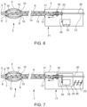
- Figures 9 and 10 show a side elevation of a further embodiment of the invention similar to the embodiments previously described in which the device 1 is provided with a tubular extraction port 27 extending laterally outwards from the handle 3 for extracting thrombus from the extraction mechanism 14.
- the device 1 is provided with a tubular extraction port 27 extending laterally outwards from the handle 3 for extracting thrombus from the extraction mechanism 14.
- Like numerals indicate like parts.
- the laterally extending extraction port 27 extends outwards from the tubular wall 12 of the distal control arm 5, and optionally the handle 3, adjacent to or proximal of the proximal end of the helical coil 15 at the handle 3 so that the extraction port 27 is in fluid communication with the extraction lumen 13.
- the extraction port 27 can be integral with the extraction mechanism 14 or, as shown in the drawing, can be configured to be part of an extraction port insert 28 inserted in and contiguous with the distal arm 5 and the extraction mechanism 14.
- the insert 28 has a cylindrical wall 29 sized and shaped to engage with the distal control arm 5 defining a helical coil 15 receiving bore 30 contiguous with the extraction lumen 13 to receive material from the helical coil 15.
- the insert 28 is further provided with an elongate cylindrical member 31 inserted in the helical coil 15 and a terminal seal 32 to prevent leakage from the insert 28.
- the extraction port 27 facilitates material (thrombus) to be removed from the extraction mechanism 14 to a location outside the handle 3 through a handle opening 33 in the handle housing 54 without leakage of thrombus inside the device 1 while still facilitating rotation of the helical coil 15.
- the central longitudinal axis of the outwardly extending extraction port 27 is oriented at an angle of 0-90 degrees to the central axis of the helical coil 15 to optimise the efficacy of thrombus exiting from the extraction mechanism 14.
- the proximal end of the helical coil 15 is attached to the cylindrical member 31 and the cylindrical member 31 is at least partially contained within the extraction port 27 so that it is possible to seal around the cylindrical member 31 which, being attached to the helical coil 15, can form part of the coil rotating mechanism 19 to rotate the helical coil 15.
- the seal 32 is located adjacent to the extraction port 27 and the cylindrical member 31 as this is the location where leakage is likely to occur.
- the cylindrical member 31 has a cylindrical member lumen for receiving a guide wire lumen 20 and is rotatable about the guide wire lumen 20 to enable the use of a guide wire with the device 1.
- an additional sealing member can form a seal between the rotatable cylindrical member lumen and the guide wire lumen 20 to prevent leakage.
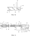
- Figure 11 shows a side elevation of a further embodiment of the invention similar to the device shown in Figure 9 in which catheter elements such as the extraction mechanism 14 of the device in the handle 3 can be translated axially as previously described.
- catheter elements such as the extraction mechanism 14 of the device in the handle 3 can be translated axially as previously described.
- the device 1 is provided with an outer sheath to prevent blood vessel trauma and, optionally, some catheter elements of the device 1 can be configured to rotate.
- the device 1 is also provided with an outer sheath 35 to prevent blood vessel trauma in use.
- the outer sheath 35 extends over the exposed portion of the proximal control arm 6 to prevent the device 1 from causing vessel trauma when navigating to a treatment zone.
- the outer sheath 35 can be axially slidably moveable as indicated by the arrows to expose and cover the expansible member 4 in use as required.
- the handle housing 54 can be provided with guides 34 adjacent the proximal arm 6 to facilitate the axial movement of the sheath 35.
- some device elements can be configured to be rotatable if desired.
- the device 1 is configured to facilitate rotation of the expansible member 4 and the distal/proximal control arms 5,6 to aid in separating thrombus from vessel walls.
- Additional guides 34 can facilitate the rotation movement thereby providing a mechanism for components to slide and rotate as required.
- the guides 34 in the handle housing 54 can be configured to facilitate axial only movement of the extraction mechanism 14 within the distal control arm 5. Accordingly, the extraction mechanism 14/distal control arm 5 can translate axially to expand and collapse the radially expansible member 4 whilst ensuring there is no rotation of the distal control arm 5 relative to the proximal control arm 6 and thereby also ensuring there is no twist introduced to the radially expansible member 4 in use.
- the extraction mechanism 14 can also be biased in a specific axial direction (either proximal or distal) by the biasing mechanism 23 to provide an axial force to the radially expansible member 4 e.g. biasing it into an expanded position.
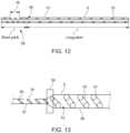
- Figures 12 to 14 show helical coil 15 configurations suitable for use in thrombectomy devices 1.
- the helical coil 15 of the extraction mechanism 14 can have a variable pitch e.g. a relatively shorter pitch (the short pitch) 58 towards or at the distal end, i.e. at or adjacent the extraction window 16 and a relatively longer pitch (the long pitch) 59 proximally of the short pitch 58.
- a relatively shorter pitch the short pitch
- the long pitch the pitch
- variable pitch provides relief/space/freedom to the materials being extracted, allowing it to be transported easier through the extraction lumen.
- a short pitch 58 at the extraction window 16 ensures that an increased number of extraction "bites" are taken from thrombus material per rotation by the helical coil 15 relative to the extraction window 16, to efficiently collect thrombus and convey the thrombus into the extraction mechanism 14 within the distal control arm 5 whilst also allowing more time for a thrombus to enter the extraction lumen 13.
- the received material is then conveyed by the helical coil 15 to the longer or increased pitch 59 of the helical coil 15 so that it is no longer tightly packed between the loops of the helical coil 15. Blockages of the extraction mechanism 14 are therefore prevented.
- the longer pitch 59 increases the extraction rate (i.e. axial movement of material) of the extraction mechanism 14.
- the distal portion of the helical coil 15 has a pitch proportional to the rotational speed and the diameter of the helical coil to allow for more effective/efficient transport of the material.
- the proximal portion of the helical coil (the longer pitch 59) has a pitch of 1-5 times the distal pitch (the shorter pitch 58 ). The Applicant has found that this pitch relationship between the shorter and longer pitch helps to ensure that the extraction mechanism 14 does not block in use.
- the shorter pitch 58 can therefore transition to the longer pitch 59 at a pitch transition zone 39 which preferably starts within a distance defined by approximately 10 times the pitch distal to the proximal end of the extraction window 16 which also minimises the distance the material travels at the short pitch 58 and hence reduces the potential for the extraction mechanism 14 to block in use. This also speeds up the overall extraction time of a captured thrombus.
- the length of the transition zone 39 is preferably less than a distance defined by 10 times the distal pitch, and is positioned proximal of the proximal end of the extraction window 16 which serves to minimise the distance extracted material travels at the shorter pitch at the extraction window 16 and hence further reduces the potential for the mechanism to get blocked during use.
- Figure 13 shows an enlarged cross-sectional side view of a helical coil 15 of an extraction mechanism 14 in which the helical coil 15 is made up of a (distal) small diameter coil portion 40 at or adjacent the extraction window 16 and a (proximal) large diameter coil portion 41 contiguous with the small diameter coil portion 40 disposed towards the handle 3.
- the extraction lumen 13 is made up of a distal relatively smaller diameter extractor lumen portion 37 (the small diameter lumen) at the extraction window 16 and a proximal relatively larger diameter lumen portion 38 (the large diameter lumen) i.e. the inner diameter of the extraction lumen 13 increases proximal to the extraction window 16.
- the transition zone 39 is defined between the small and large diameter lumens 37,38.
- the small diameter coil may be the same as the large diameter coil within the small and large diameter lumen.
- the large diameter lumen 38 provides relief/space/freedom to extracted material allowing it to be transported easier through the extraction lumen 13.
- the diameter of the diameter of the helical coil 15 preferably increases at the large diameter coil portion 41 adjacent to the large diameter lumen 38. This prevents extracted material from flowing uncontrollably between the outer diameter or edge of the helical coil 15 and the internal diameter or edge of the extraction lumen 13.
- Figure 14 shows an enlarged cross-sectional side view of an alternative helical coil 15 in which the elongate wire of the helical coil 15 has a variable thickness or cross-sectional area. More particularly, the elongate wire of the helical coil 15 has a relatively larger cross-sectional area portion 42 (the large cross-sectional area portion) and a relatively smaller cross-sectional area portion 43 (the small cross-sectional area portion).
- the small cross-sectional area portion 43 is disposed towards the proximal end of the extraction lumen while large cross-sectional area portion is disposed towards the distal end at the extraction window 16 i.e. the cross-sectional area of the helical coil wire reduces proximal to the proximal end of the extraction tube window 16 to provide space/relief to the material being transported through the extraction lumen 13 preventing it from getting blocked.
- Figures 15 to 18 show various optional configurations of the extraction window 16 on the distal control arm 5.
- the extraction window can be positioned within and/or proximal and/or distal to the radially expansible member 4 and is made up of an elongate axial window 16 defined in the tubular wall 12 of the distal control arm 5 to provide access to the helical coil 15 of the extraction mechanism 14 in the extraction lumen 13.
- the extraction window 16 located or positioned within the radially expansible member 4 on the distal control arm 5.
- the extraction window 16 is located towards the distal end 7 of the radially expansible member 4 Accordingly, the extraction window 16 effectively removes material from inside the radially expansible member 4 which can gather at the distal end 7 of the radially expansible member 4. Accordingly, in use, such an extraction window 16 can remove thrombus material within and proximal of the radially expansible member 4 and also remove any material that may be pushed proximal of the radially expansible member 4.
- Figure 16 shows an alternative arrangement in which the extraction window 16 is located proximal to and outside the radially expansible member 4 on the distal arm 5 i.e. proximal of the proximal end 8 of the radially expansible member 4. This serves to remove material proximal of the radially expansible member 4 which in use may be pushed proximal of the radially expansible member 4 and must therefore be extracted.
- the thrombectomy device 1 can further include a macerator or cutting mechanism to macerate extracted material and the extraction window 16 and the helical coil 15 can in combination co-operate to form the macerator/cutting mechanism. Accordingly, material being extracted can be macerated via a shearing action provided by the interaction between the helical coil 15 and the extraction window 16.
- the helical coil may comprise of coiled wire(s) or cut tube profiles with different cross sectional profiles, including round, ovoid, square, rectangular, triangular or other profiles suitable for cutting and extraction when rotated.
- Figures 17 and 18 show a radially expansible member 4 with the elongate extraction window 16 located within the radially expansible member as shown in Figure 15 .
- the elongate extraction window 16 is shaped and configured to have both a longitudinal and circumferential axis along the distal control arm 5 i.e. the extraction window 16 is disposed circumferentially about the distal control arm 5.
- the circumferential axis increases/decreases the shearing action between the helical coil 15 and the extraction window 16 to effectively generate a scissor-like cutting action between the helical coil 15 and the extraction window 16 to provide an optimal macerating action on the material being extracted.
- Figures 19 and 20 show a radially expansible member 4 suitable for use with a thrombectomy device 1.
- the radially expansible member 4 is in the form of a braided cage 4 having distinct or distinguishable distal, central flexible and proximal zones 44, 45, 46 respectively formed for example from braided or twisted material such as wires 56 which in turn define apertures 57 in the radially expansible member 4.
- the radially expansible member 4 has a distal end 7 in the distal zone 44 and a proximal end 8 defining a thrombus receiving opening 48 in the proximal zone 46.
- the radially expansible member may also be formed from a cut or formed profile to form the desired distal, central flexible and proximal zones 44, 45, 46 respectively.
- the distinct zones 44, 45, 46 within the radially expansible member 4 can be individually tailored to give different mechanical properties as required.
- the distal zone 44 has a reduced porosity relative to the proximal zone 46 i.e. the apertures 57 at the proximal end 8 are large to accept thrombus into the radially expansible member 4 and the apertures 57 at the distal end 7 are small to prevent thrombus from leaving the radially expansible member 4.
- the distal end 7 may also be coated or attached to a permeable or impermeable membrane to further reduce or eliminate the porosity of the distal end 7.
- the central zone 45 has a circumferential edge 47 defining the thrombus receiving opening 48.
- the circumferential edge 47 has a serrated configuration and acts as a cutting wire to separate thrombus from vessel walls.
- the circumferential edge 47 can have a sharp or angled edge having other outline shapes as required.
- the central zone 45 is more radially compliant than the distal and proximal zones 44, 46 respectively. Accordingly, when the radially expansible member 4 is expanded, the central zone 45 expands first so that the circumferential edge 47 is at (or close to) the largest diameter possible for the radially expansible member 4.
- Figure 20 shows a plan view of a suitable braid pattern 49 of a portion of the radially expansible member 4 at the distal, central and proximal zones 44, 45, 46 respectively.
- the braid pattern 49 is made up braided single wires 50 defining the apertures 57 in the distal zone 44, twisted double wires (i.e. two twisted wires) 51 forming single braid wires 51 in the transition zone 45 and four twisted wires 52 forming single braid wires 51 in the proximal zone 46.
- the pattern 49 may be made from a cut or formed profile, where the proximal members may optionally be comprised of a larger cross sectional profile or of a different material to provide additional strength or resistance to bending during use.
- the radially expansible member 4 is made up of varying arrangements of twisted braided wires to form the proximal, central and distal zones 44, 45, 46. Varying the wires as described above varies the properties of the radially expansible member 4 in the distal, central and proximal zones 44, 45, 46 so that the apertures 57 at the proximal end 8 are large to accept the thrombus into the radially expansible member 4 and the apertures 57 at the distal end 7 are small to prevent the thrombus from leaving the radially expansible member 4.
- transition from single wires 50 to twisted wires 51, 52 creates a central zone 45 in the structure at the circumferential edge 47 that is the first to expand in use and ensures the circumferential edge 47 is at or close to the largest outer diameter of the radially expansible member 4.
Landscapes
- Health & Medical Sciences (AREA)
- Surgery (AREA)
- Life Sciences & Earth Sciences (AREA)
- Medical Informatics (AREA)
- Nuclear Medicine, Radiotherapy & Molecular Imaging (AREA)
- Engineering & Computer Science (AREA)
- Biomedical Technology (AREA)
- Heart & Thoracic Surgery (AREA)
- Vascular Medicine (AREA)
- Molecular Biology (AREA)
- Animal Behavior & Ethology (AREA)
- General Health & Medical Sciences (AREA)
- Public Health (AREA)
- Veterinary Medicine (AREA)
- Orthopedic Medicine & Surgery (AREA)
- Surgical Instruments (AREA)
Claims (13)
- Thrombektomievorrichtung (1) zur Entfernung von Material aus einem Körperlumen, umfassend:einen Griff (3);ein sich von dem Griff (3) erstreckendes Katheterelement (2), das einen distalen Steuerarm (5), der an einem proximalen Gehäuse (24) in dem Griff (3) angebracht ist, und einen proximalen Steuerarm (6) hat;ein radial ausdehnbares Element (4), das mit dem distalen Steuerarm (5) neben dem distalen Ende (7) des radial ausdehnbaren Elements (4) und neben dem proximalen Arm (6) an einem proximalen Ende (8) des radial ausdehnbaren Elements (4) gekoppelt ist, das als Reaktion auf die axiale Bewegung des distalen Steuerarms (5) relativ zum proximalen Steuerarm (6) zwischen einer zusammengezogenen Stellung und einer ausgedehnten Thrombusfangstellung radial ausdehnbar ist;einen Thrombusextraktionsmechanismus (14), der eine gewendelte Spule (15) umfasst, die sich durch den distalen Steuerarm (5) erstreckt; undeinen Spulendrehungsmechanismus (19), der an dem distalen Steuerarm (5) angebracht ist und wobei der Spulendrehungsmechanismus (19) sich in dem oder angrenzend an den Griff (3) befindet;wobei der Extraktionsmechanismus (14) und der distale Steuerarm (5) so konfiguriert sind, dass sie gekoppelt sind, um synchronisierte axiale Bewegung zu bewirken, so dass der Extraktionsmechanismus (14) in Bezug auf den distalen Steuerarm (5) positionsbezogen axial befestigt ist;wobei der Spulendrehungsmechanismus (19) zum axialen Verschieben in dem oder angrenzend an das Gehäuse (24) synchron mit dem distalen Steuerarm (5) konfiguriert ist.
- Thrombektomievorrichtung (1) nach Anspruch 1, wobei der Extraktionsmechanismus (14) und der distale Steuerarm (5) so konfiguriert sind, dass sie am Griff (3) gekoppelt sind, um die synchronisierte axiale Bewegung zu bewirken.
- Thrombektomievorrichtung (1) nach Anspruch 1 oder Anspruch 2, ferner umfassend mindestens ein Extraktionsfenster (16) am distalen Steuerarm (5), wobei das Extraktionsfenster (16) in Bezug auf die gewendelte Spule (15) positionsbezogen axial befestigt ist und, wahlweise, das Extraktionsfenster (16) eine Achse in Längs- und in Umfangsrichtung entlang des distalen Steuerarms (5) hat.
- Thrombektomievorrichtung (1) nach Anspruch 3, wobei die gewendelte Spule (15) an dem oder angrenzend an das Extraktionsfenster (16) eine kürzere Steigung und zum Griff (3) hin eine längere Steigung umfasst.
- Thrombektomievorrichtung (1) nach Anspruch 3, wobei die gewendelte Spule (15) einen distalen Spulenteil (40) mit kleinem Durchmesser an dem oder angrenzend an das Extraktionsfenster (16) und einen proximalen Spulenteil (41) mit großem Durchmesser, der mit dem Spulenteil (40) mit kleinem Durchmesser zum Griff (3) hin zusammenhängt, umfasst.
- Thrombektomievorrichtung (1) nach Anspruch 3, wobei die gewendelte Spule (15) eine variable Dicke oder Querschnittsfläche hat.
- Thrombektomievorrichtung (1) nach einem der Ansprüche 1 bis 6, wobei der Spulendrehungsmechanismus (19) einen Antriebsstrang (25) umfasst, der gleitfähig mit der gewendelten Spule (15) verbunden ist, um die axiale Verschiebung der gewendelten Spule (15) zu erleichtern.
- Thrombektomievorrichtung (1) nach einem der Ansprüche 1 bis 7, wobei die gewendelte Spule (15) und der distale Steuerarm (5) an einem Vorspannmechanismus (23) im Griff (3) gekoppelt sind.
- Thrombektomievorrichtung (1) nach Anspruch 8, wobei der Vorspannmechanismus (23) den Extraktionsmechanismus (14) proximal und/oder distal relativ zum proximalen Arm (6) vorspannt.
- Thrombektomievorrichtung (1) nach Anspruch 8 oder Anspruch 9, ferner umfassend einen manuell bedienbaren Überbrückungsmechanismus (36) zum Überbrücken des Vorspannmechanismus (23).
- Thrombektomievorrichtung (1) nach einem der Ansprüche 1 bis 10, ferner umfassend ein Führungsdrahtlumen (20) durch das Katheterelement (2).
- Thrombektomievorrichtung (1) nach Anspruch 11, wobei die gewendelte Spule (15) über dem Führungsdrahtlumen (20) positioniert ist und das Führungsdrahtlumen (20) nicht drehbar mit der gewendelten Spule (15) gekoppelt ist.
- Thrombektomievorrichtung (1) nach einem der Ansprüche 1 bis 12, ferner umfassend einen Extraktionsanschluss (27) in Fluidverbindung mit dem Extraktionsmechanismus (14) zum Extrahieren eines Thrombus aus dem Extraktionsmechanismus (14).
Priority Applications (3)
| Application Number | Priority Date | Filing Date | Title |
|---|---|---|---|
| EP21169975.6A EP4079239B1 (de) | 2021-04-22 | 2021-04-22 | Thrombektomievorrichtung |
| US18/287,430 US20240215997A1 (en) | 2021-04-22 | 2022-04-22 | A thrombectomy device |
| PCT/EP2022/060671 WO2022223772A1 (en) | 2021-04-22 | 2022-04-22 | A thrombectomy device |
Applications Claiming Priority (1)
| Application Number | Priority Date | Filing Date | Title |
|---|---|---|---|
| EP21169975.6A EP4079239B1 (de) | 2021-04-22 | 2021-04-22 | Thrombektomievorrichtung |
Publications (3)
| Publication Number | Publication Date |
|---|---|
| EP4079239A1 EP4079239A1 (de) | 2022-10-26 |
| EP4079239B1 true EP4079239B1 (de) | 2025-07-02 |
| EP4079239C0 EP4079239C0 (de) | 2025-07-02 |
Family
ID=75659804
Family Applications (1)
| Application Number | Title | Priority Date | Filing Date |
|---|---|---|---|
| EP21169975.6A Active EP4079239B1 (de) | 2021-04-22 | 2021-04-22 | Thrombektomievorrichtung |
Country Status (3)
| Country | Link |
|---|---|
| US (1) | US20240215997A1 (de) |
| EP (1) | EP4079239B1 (de) |
| WO (1) | WO2022223772A1 (de) |
Families Citing this family (3)
| Publication number | Priority date | Publication date | Assignee | Title |
|---|---|---|---|---|
| AU2021283979A1 (en) | 2020-06-05 | 2023-01-19 | Inari Medical, Inc. | Recapturable funnel catheters, and associated systems and methods |
| WO2024184276A1 (en) * | 2023-03-03 | 2024-09-12 | Vetex Medical Ltd. | Multi-function thrombectomy hub |
| WO2025008042A1 (en) * | 2023-07-03 | 2025-01-09 | Straub Medical Ag | Atherectomy catheter and atherectomy system |
Family Cites Families (5)
| Publication number | Priority date | Publication date | Assignee | Title |
|---|---|---|---|---|
| EP0117519A1 (de) * | 1983-02-23 | 1984-09-05 | Johannes Dipl.-Ing. Theermann | Katheter |
| US7655016B2 (en) * | 1999-09-17 | 2010-02-02 | Covidien | Mechanical pump for removal of fragmented matter and methods of manufacture and use |
| US20010031981A1 (en) * | 2000-03-31 | 2001-10-18 | Evans Michael A. | Method and device for locating guidewire and treating chronic total occlusions |
| EP3305220B8 (de) * | 2013-03-15 | 2022-04-20 | Vetex Medical Limited | Zur beseitigung von materie aus dem inneren eines lumens und aus der wand eines körperlumens geeignete vorrichtung |
| EP3017775A1 (de) * | 2014-11-07 | 2016-05-11 | National University of Ireland, Galway | Thrombektomievorrichtung |
-
2021
- 2021-04-22 EP EP21169975.6A patent/EP4079239B1/de active Active
-
2022
- 2022-04-22 US US18/287,430 patent/US20240215997A1/en active Pending
- 2022-04-22 WO PCT/EP2022/060671 patent/WO2022223772A1/en not_active Ceased
Also Published As
| Publication number | Publication date |
|---|---|
| EP4079239C0 (de) | 2025-07-02 |
| US20240215997A1 (en) | 2024-07-04 |
| WO2022223772A1 (en) | 2022-10-27 |
| EP4079239A1 (de) | 2022-10-26 |
Similar Documents
| Publication | Publication Date | Title |
|---|---|---|
| US20240215997A1 (en) | A thrombectomy device | |
| JP7536618B2 (ja) | 外側シース及び内側カテーテルを有する血塊回収装置 | |
| US12076036B2 (en) | Thrombectomy systems and devices with aspiration, and methods of use thereof | |
| EP3902487B1 (de) | Extraktionskorb | |
| US6027514A (en) | Apparatus and method for removing occluding material from body lumens | |
| US9005237B2 (en) | Device and method for clot capture | |
| JP6294933B2 (ja) | 身体管腔のための組織除去カテーテル | |
| US10258452B2 (en) | Device and method for clot engagement and capture | |
| US9034008B2 (en) | Device and method involving stabilization during clot removal | |
| US8864792B2 (en) | Device and method for clot engagement | |
| US6454775B1 (en) | Systems and methods for clot disruption and retrieval | |
| US6652548B2 (en) | Expansible shearing catheters for thrombus removal | |
| US9700347B2 (en) | Adaptive rotary catheter for opening obstructed bodily vessels | |
| WO2013072777A9 (en) | Clot removal devices and methods | |
| WO1995006437A1 (en) | Bi-axial cutter apparatus for catheter | |
| WO2025035131A1 (en) | Method and apparatus for suction during surgical procedures | |
| EP3030165B1 (de) | Blutgerinnselentfernungsgerät mit lenkbaren element |
Legal Events
| Date | Code | Title | Description |
|---|---|---|---|
| PUAI | Public reference made under article 153(3) epc to a published international application that has entered the european phase |
Free format text: ORIGINAL CODE: 0009012 |
|
| STAA | Information on the status of an ep patent application or granted ep patent |
Free format text: STATUS: THE APPLICATION HAS BEEN PUBLISHED |
|
| AK | Designated contracting states |
Kind code of ref document: A1 Designated state(s): AL AT BE BG CH CY CZ DE DK EE ES FI FR GB GR HR HU IE IS IT LI LT LU LV MC MK MT NL NO PL PT RO RS SE SI SK SM TR |
|
| STAA | Information on the status of an ep patent application or granted ep patent |
Free format text: STATUS: REQUEST FOR EXAMINATION WAS MADE |
|
| 17P | Request for examination filed |
Effective date: 20230425 |
|
| RBV | Designated contracting states (corrected) |
Designated state(s): AL AT BE BG CH CY CZ DE DK EE ES FI FR GB GR HR HU IE IS IT LI LT LU LV MC MK MT NL NO PL PT RO RS SE SI SK SM TR |
|
| STAA | Information on the status of an ep patent application or granted ep patent |
Free format text: STATUS: EXAMINATION IS IN PROGRESS |
|
| 17Q | First examination report despatched |
Effective date: 20231207 |
|
| RIC1 | Information provided on ipc code assigned before grant |
Ipc: A61B 90/00 20160101ALN20241212BHEP Ipc: A61B 17/22 20060101ALN20241212BHEP Ipc: A61B 17/221 20060101ALI20241212BHEP Ipc: A61B 17/3207 20060101AFI20241212BHEP |
|
| GRAP | Despatch of communication of intention to grant a patent |
Free format text: ORIGINAL CODE: EPIDOSNIGR1 |
|
| STAA | Information on the status of an ep patent application or granted ep patent |
Free format text: STATUS: GRANT OF PATENT IS INTENDED |
|
| RIC1 | Information provided on ipc code assigned before grant |
Ipc: A61B 90/00 20160101ALN20250109BHEP Ipc: A61B 17/22 20060101ALN20250109BHEP Ipc: A61B 17/221 20060101ALI20250109BHEP Ipc: A61B 17/3207 20060101AFI20250109BHEP |
|
| INTG | Intention to grant announced |
Effective date: 20250129 |
|
| RIN1 | Information on inventor provided before grant (corrected) |
Inventor name: BRUZZI, MARK Inventor name: EGAN, JOHN Inventor name: MOLLOY, SHANE Inventor name: O'BRIEN, CON |
|
| GRAS | Grant fee paid |
Free format text: ORIGINAL CODE: EPIDOSNIGR3 |
|
| GRAA | (expected) grant |
Free format text: ORIGINAL CODE: 0009210 |
|
| STAA | Information on the status of an ep patent application or granted ep patent |
Free format text: STATUS: THE PATENT HAS BEEN GRANTED |
|
| AK | Designated contracting states |
Kind code of ref document: B1 Designated state(s): AL AT BE BG CH CY CZ DE DK EE ES FI FR GB GR HR HU IE IS IT LI LT LU LV MC MK MT NL NO PL PT RO RS SE SI SK SM TR |
|
| REG | Reference to a national code |
Ref country code: GB Ref legal event code: FG4D |
|
| REG | Reference to a national code |
Ref country code: CH Ref legal event code: EP |
|
| REG | Reference to a national code |
Ref country code: DE Ref legal event code: R096 Ref document number: 602021033175 Country of ref document: DE |
|
| REG | Reference to a national code |
Ref country code: IE Ref legal event code: FG4D |
|
| U01 | Request for unitary effect filed |
Effective date: 20250731 |
|
| U07 | Unitary effect registered |
Designated state(s): AT BE BG DE DK EE FI FR IT LT LU LV MT NL PT RO SE SI Effective date: 20250811 |
|
| PG25 | Lapsed in a contracting state [announced via postgrant information from national office to epo] |
Ref country code: IS Free format text: LAPSE BECAUSE OF FAILURE TO SUBMIT A TRANSLATION OF THE DESCRIPTION OR TO PAY THE FEE WITHIN THE PRESCRIBED TIME-LIMIT Effective date: 20251102 |
|
| PG25 | Lapsed in a contracting state [announced via postgrant information from national office to epo] |
Ref country code: NO Free format text: LAPSE BECAUSE OF FAILURE TO SUBMIT A TRANSLATION OF THE DESCRIPTION OR TO PAY THE FEE WITHIN THE PRESCRIBED TIME-LIMIT Effective date: 20251002 |
|
| PG25 | Lapsed in a contracting state [announced via postgrant information from national office to epo] |
Ref country code: HR Free format text: LAPSE BECAUSE OF FAILURE TO SUBMIT A TRANSLATION OF THE DESCRIPTION OR TO PAY THE FEE WITHIN THE PRESCRIBED TIME-LIMIT Effective date: 20250702 |
|
| PG25 | Lapsed in a contracting state [announced via postgrant information from national office to epo] |
Ref country code: GR Free format text: LAPSE BECAUSE OF FAILURE TO SUBMIT A TRANSLATION OF THE DESCRIPTION OR TO PAY THE FEE WITHIN THE PRESCRIBED TIME-LIMIT Effective date: 20251003 |
|
| PG25 | Lapsed in a contracting state [announced via postgrant information from national office to epo] |
Ref country code: CZ Free format text: LAPSE BECAUSE OF FAILURE TO SUBMIT A TRANSLATION OF THE DESCRIPTION OR TO PAY THE FEE WITHIN THE PRESCRIBED TIME-LIMIT Effective date: 20250702 |
|
| PG25 | Lapsed in a contracting state [announced via postgrant information from national office to epo] |
Ref country code: PL Free format text: LAPSE BECAUSE OF FAILURE TO SUBMIT A TRANSLATION OF THE DESCRIPTION OR TO PAY THE FEE WITHIN THE PRESCRIBED TIME-LIMIT Effective date: 20250702 |
|
| PG25 | Lapsed in a contracting state [announced via postgrant information from national office to epo] |
Ref country code: RS Free format text: LAPSE BECAUSE OF FAILURE TO SUBMIT A TRANSLATION OF THE DESCRIPTION OR TO PAY THE FEE WITHIN THE PRESCRIBED TIME-LIMIT Effective date: 20251002 |
|
| PG25 | Lapsed in a contracting state [announced via postgrant information from national office to epo] |
Ref country code: ES Free format text: LAPSE BECAUSE OF FAILURE TO SUBMIT A TRANSLATION OF THE DESCRIPTION OR TO PAY THE FEE WITHIN THE PRESCRIBED TIME-LIMIT Effective date: 20250702 |
|
| PG25 | Lapsed in a contracting state [announced via postgrant information from national office to epo] |
Ref country code: SM Free format text: LAPSE BECAUSE OF FAILURE TO SUBMIT A TRANSLATION OF THE DESCRIPTION OR TO PAY THE FEE WITHIN THE PRESCRIBED TIME-LIMIT Effective date: 20250702 |