EP4079128A1 - Work machine - Google Patents
Work machine Download PDFInfo
- Publication number
- EP4079128A1 EP4079128A1 EP20904142.5A EP20904142A EP4079128A1 EP 4079128 A1 EP4079128 A1 EP 4079128A1 EP 20904142 A EP20904142 A EP 20904142A EP 4079128 A1 EP4079128 A1 EP 4079128A1
- Authority
- EP
- European Patent Office
- Prior art keywords
- work
- range
- spreading
- working
- spreader
- Prior art date
- Legal status (The legal status is an assumption and is not a legal conclusion. Google has not performed a legal analysis and makes no representation as to the accuracy of the status listed.)
- Pending
Links
Images









Classifications
-
- A—HUMAN NECESSITIES
- A01—AGRICULTURE; FORESTRY; ANIMAL HUSBANDRY; HUNTING; TRAPPING; FISHING
- A01B—SOIL WORKING IN AGRICULTURE OR FORESTRY; PARTS, DETAILS, OR ACCESSORIES OF AGRICULTURAL MACHINES OR IMPLEMENTS, IN GENERAL
- A01B69/00—Steering of agricultural machines or implements; Guiding agricultural machines or implements on a desired track
- A01B69/003—Steering or guiding of machines or implements pushed or pulled by or mounted on agricultural vehicles such as tractors, e.g. by lateral shifting of the towing connection
- A01B69/004—Steering or guiding of machines or implements pushed or pulled by or mounted on agricultural vehicles such as tractors, e.g. by lateral shifting of the towing connection automatic
-
- A—HUMAN NECESSITIES
- A01—AGRICULTURE; FORESTRY; ANIMAL HUSBANDRY; HUNTING; TRAPPING; FISHING
- A01B—SOIL WORKING IN AGRICULTURE OR FORESTRY; PARTS, DETAILS, OR ACCESSORIES OF AGRICULTURAL MACHINES OR IMPLEMENTS, IN GENERAL
- A01B69/00—Steering of agricultural machines or implements; Guiding agricultural machines or implements on a desired track
- A01B69/007—Steering or guiding of agricultural vehicles, e.g. steering of the tractor to keep the plough in the furrow
- A01B69/008—Steering or guiding of agricultural vehicles, e.g. steering of the tractor to keep the plough in the furrow automatic
-
- A—HUMAN NECESSITIES
- A01—AGRICULTURE; FORESTRY; ANIMAL HUSBANDRY; HUNTING; TRAPPING; FISHING
- A01C—PLANTING; SOWING; FERTILISING
- A01C23/00—Distributing devices specially adapted for liquid manure or other fertilising liquid, including ammonia, e.g. transport tanks or sprinkling wagons
- A01C23/007—Metering or regulating systems
-
- G—PHYSICS
- G05—CONTROLLING; REGULATING
- G05D—SYSTEMS FOR CONTROLLING OR REGULATING NON-ELECTRIC VARIABLES
- G05D1/00—Control of position, course, altitude or attitude of land, water, air or space vehicles, e.g. using automatic pilots
- G05D1/02—Control of position or course in two dimensions
- G05D1/021—Control of position or course in two dimensions specially adapted to land vehicles
- G05D1/0212—Control of position or course in two dimensions specially adapted to land vehicles with means for defining a desired trajectory
- G05D1/0219—Control of position or course in two dimensions specially adapted to land vehicles with means for defining a desired trajectory ensuring the processing of the whole working surface
-
- A—HUMAN NECESSITIES
- A01—AGRICULTURE; FORESTRY; ANIMAL HUSBANDRY; HUNTING; TRAPPING; FISHING
- A01C—PLANTING; SOWING; FERTILISING
- A01C21/00—Methods of fertilising, sowing or planting
- A01C21/005—Following a specific plan, e.g. pattern
-
- A—HUMAN NECESSITIES
- A01—AGRICULTURE; FORESTRY; ANIMAL HUSBANDRY; HUNTING; TRAPPING; FISHING
- A01G—HORTICULTURE; CULTIVATION OF VEGETABLES, FLOWERS, RICE, FRUIT, VINES, HOPS OR SEAWEED; FORESTRY; WATERING
- A01G25/00—Watering gardens, fields, sports grounds or the like
- A01G25/16—Control of watering
-
- A—HUMAN NECESSITIES
- A01—AGRICULTURE; FORESTRY; ANIMAL HUSBANDRY; HUNTING; TRAPPING; FISHING
- A01M—CATCHING, TRAPPING OR SCARING OF ANIMALS; APPARATUS FOR THE DESTRUCTION OF NOXIOUS ANIMALS OR NOXIOUS PLANTS
- A01M7/00—Special adaptations or arrangements of liquid-spraying apparatus for purposes covered by this subclass
- A01M7/0089—Regulating or controlling systems
-
- B—PERFORMING OPERATIONS; TRANSPORTING
- B62—LAND VEHICLES FOR TRAVELLING OTHERWISE THAN ON RAILS
- B62D—MOTOR VEHICLES; TRAILERS
- B62D49/00—Tractors
- B62D49/06—Tractors adapted for multi-purpose use
Definitions
- the present invention relates to a working machine having a working device linked thereto.
- Patent document 1 The technique disclosed in Patent document 1 is known as a technique to prepare a travel route (work/travel line) for automatic travel of a working machine such as tractor.
- a working vehicle (working machine) of Patent document 1 includes an acquiring unit to acquire position data of an outer periphery of an agricultural field, and a work setting unit to set, on the basis of the position data, a work/travel line for travel of a travel machine body (machine body) in the agricultural field.
- Patent document 1 Japanese Unexamined Patent Application Publication No. 2018-39
- a work/travel line (planned travel route) can be prepared and work can be done while automatic travel is performed along the work/travel line.
- the working device is a spreader such as a fertilizer spreader or an agricultural chemical spreader
- a work range in a front-rear direction differs depending on the category of work done by the working device, some areas may be left with no work done and work efficiency may decrease.
- the present invention was made in order to solve such an issue of the conventional technique, and an object thereof is to provide a working machine that is capable of accurately and efficiently doing work at intended positions.
- a working machine includes a machine body, a linkage capable of linking a working device to the machine body, a spreader being one of types of the working device, an automatic travel control unit to cause the machine body to perform automatic travel according to a planned travel route, a range acquisition unit to acquire a spreading work range that is a range where spreading work is done by the spreader in a front-rear direction thereof, and a work setting unit to set a work start position and a work end position for the spreader so that the work start position and the work end position are at different positions according to the spreading work range acquired by the range acquisition unit.
- the working machine further includes an input device to receive input of the spreading work range such that the spreading work range is associated with the spreader, wherein the range acquisition unit acquires the spreading work range received by the input device.
- the working machine further includes a storage unit to store the spreading work range received by the input device, wherein the input device is a display device to display an input screen to receive input of the spreading work range, and the storage unit stores the spreading work range inputted into and received by the input screen and the spreader corresponding to the spreading work range such that the spreading work range and the spreader are associated with each other.
- the input device is a display device to display an input screen to receive input of the spreading work range
- the storage unit stores the spreading work range inputted into and received by the input screen and the spreader corresponding to the spreading work range such that the spreading work range and the spreader are associated with each other.
- the working machine further includes a storage unit to store the spreading work range received by the input device, wherein the storage unit stores another type of the working device other than the spreader and a pre-set work range such that the other type of the working device and the pre-set work range are associated with each other, the range acquisition unit acquires, if the working device linked to the linkage is the spreader, the spreading work range inputted into and received by the input device and associated with the spreader from the storage unit, and acquires, if the working device linked to the linkage is the other type of the working device other than the spreader, the work range from the storage unit; and the work setting unit sets the work start position and the work end position for the working device linked to the linkage so that the work start position and the work end position are at different positions according to the spreading work range or the work range acquired by the range acquisition unit.
- the working machine further includes a control device to control the working device linked to the linkage according to the work start position and the work end position set by the work setting unit, wherein the control device causes the working device linked to the linkage to start doing work when the working device has passed through the work start position and causes the working device to stop doing the work when the working device has passed through the work end position.
- the working machine further includes a route preparation unit to prepare the planned travel route, wherein the work setting unit sets, according to the working device linked to the linkage, the work start position and the work end position for the working device on the planned travel route.
- the above-described working machine is capable of accurately and efficiently doing work at intended positions.
- FIG. 14 illustrates a tractor, which is an example of a working machine 1.
- the working machine 1 is discussed using a tractor as an example, but the working machine 1 is not limited to a tractor and may be a rice transplanter or a combine.
- descriptions are based on the assumption that the front of the working machine 1 as seen from an operator (driver) seated on an operator's seat 10 (indicated by arrow A1 in FIGS. 3B , 3C , and 14 ) is "front", the rear of the working machine 1 as seen from the operator is "rear” (indicated by arrow A2 in FIGS.
- the left side of the working machine 1 as seen from the operator is “left” (near side in FIG. 14 , indicated by arrow B 1 in FIGS. 3B and 3C ), and the right side of the working machine 1 as seen from the operator is “right” (far side in FIG. 14 , indicated by arrow B2 in FIGS. 3B and 3C ).
- the descriptions are also based on the assumption that a horizontal direction orthogonal to a front-rear direction of the working machine 1 is a width direction.
- the working machine 1 includes: a machine body (travel vehicle body) 3 with a traveling device 7; a prime mover 4; and a transmission 5.
- the traveling device 7 includes front wheel(s) 7F and rear wheel(s) 7R.
- the front wheels 7F may be tire-shaped wheels and may be crawler-shaped wheels.
- the rear wheels 7R also may be tire-shaped wheels and may be crawler-shaped wheels.
- the prime mover 4 is a diesel engine, an electric motor, and/or the like.
- the transmission 5 is capable of changing driving forces for the traveling device 7 by changing speed stages and switching the traveling state of the traveling device 7 between forward and rearward traveling states.
- the machine body 3 is provided with a cabin 9, and the cabin 9 is provided with the operator's seat 10 therein.
- the machine body 3 is provided with a linkage at the rear thereof.
- the linkage is a swinging drawbar which connects a working device 2 and the machine body 3 but does not raise or lower the working device 2, a raising/lowering device 8 which is composed of a three-point linkage or the like and which raises and lowers the working device 2, or the like.
- the working device 2 can be attached to and detached from the linkage. By linking the working device 2 to the linkage, it is possible for the machine body 3 to tow the working device 2.
- the working device 2 at least include spreaders. Examples of the spreaders include a fertilizer spreader (broadcaster), an agricultural chemical spreader for spreading agricultural chemicals, a water spreader for spreading water, and the like.
- Examples of the working device further include a cultivator for cultivation, a transplanter for planting, a mower for mowing grass or the like, a tedder for tedding grass or the like, a rake for raking grass or the like, a baler for baling grass or the like, and the like, in addition to the above-described spreaders.
- a cultivator for cultivation a transplanter for planting, a mower for mowing grass or the like, a tedder for tedding grass or the like, a rake for raking grass or the like, a baler for baling grass or the like, and the like, in addition to the above-described spreaders.
- a fertilizer spreader as a spreader is linked to the linkage.
- the raising/lowering device 8 includes lift arms 8a, lower links 8b, a top link 8c, lift rods 8d, and lift cylinders 8e.
- a front end of each lift arm 8a is supported on an upper rear portion of a case (transmission case) housing the transmission 5 such that the lift arm 8a is swingable up and down.
- the lift arm 8a is driven by a corresponding lift cylinder 8e to swing (raised or lowered).
- the lift cylinder 8e is composed of a hydraulic cylinder.
- the lift cylinder 8e is connected to a hydraulic pump via a control valve 36.
- the control valve 36 is a solenoid valve or the like to cause the lift cylinder 8e to extend and retract.
- each lower link 8b is supported on a lower rear portion of the transmission 5 such that the lower link 8b is swingable up and down.
- a front end of the top link 8c is supported, at a position higher than the lower link 8b, on a rear portion of the transmission 5 such that the top link 8c is swingable up and down.
- Each lift rod 8d connects a corresponding lift arm 8a and a corresponding lower link 8b.
- the working device 2 is linked to rear portions of the lower links 8b and the top link 8c. When the lift cylinders 8e are driven (extend or retract), the lift arms 8a ascend or descend, and the lower links 8b connected to the lift arms 8a via the lift rods 8d also ascend or descend. With this, the working device 2 swings up or down (raised or lowered) about front portions of the lower links 8b.
- the working machine 1 includes a steering unit 29.
- the steering unit 29 includes a steering wheel 30, a rotation shaft (steering shaft) 31 which rotates as the steering wheel 30 rotates, and an assist mechanism (power steering mechanism) 32 to assist steering performed using the steering wheel 30.
- the assist mechanism 32 includes a hydraulic pump 33, a control valve 34 supplied with hydraulic fluid discharged from the hydraulic pump 33, and a steering cylinder 35 which is actuated by the control valve 34.
- the control valve 34 is a solenoid valve which is actuated according to a control signal.
- the control valve 34 is, for example, a three-way switching valve which achieves multi-position switching by movement of a spool or the like. The positions of the control valve 34 can also be switched by steering by the steering shaft 31.
- the steering cylinder 35 is connected to arms (knuckle arms) which change the orientation of the front wheels 7F.
- the steering wheel 30 upon operation of the steering wheel 30, the position and the degree of opening of the control valve 34 change according to the steering wheel 30, and the steering cylinder 35 extends or retracts leftward or rightward according to the position and the degree of opening of the control valve 34, making it possible to change the steering direction of the front wheels 7F.
- the foregoing steering unit 29 is an example, and the foregoing configuration does not imply limitation.
- the working machine 1 includes a positioning device 40.
- the positioning device 40 is capable of detecting the position thereof (measured position information including latitude and longitude) by a satellite positioning system (positioning satellites) such as D-GPS, GPS, GLONASS, BeiDou, Galileo, and/or Michibiki.
- the positioning device 40 receives satellite signals (positions of positioning satellites, time of transmission, correction information, and/or the like) from the positioning satellites, and detects the position (e.g., latitude and longitude) of the working machine 1, i.e., a machine body position VP1, on the basis of the satellite signals.
- the positioning device 40 includes a receiver 41 and an inertial measurement unit (IMU) 42.
- IMU inertial measurement unit
- the receiver 41 is a device which includes an antenna and/or the like and which receives satellite signals from the positioning satellites, and is attached to the machine body 3 separately from the inertial measurement unit 42.
- the receiver 41 is attached to the machine body 3, e.g., the cabin 9. Note that the location at which the receiver 41 is attached is not limited to those described in embodiments.
- the inertial measurement unit 42 includes an acceleration sensor to detect acceleration, a gyroscope sensor to detect angular velocity, and/or the like.
- the inertial measurement unit 42 is provided on the machine body 3, for example, below the operator's seat 10, and is capable of detecting the roll angle, pitch angle, yaw angle, and/or the like of the machine body 3.
- the working machine 1 includes an input device.
- the input device is a device to receive various settings regarding the working machine 1.
- the input device is, for example, a display device 50 which is operable and which displays predetermined input screens M5 and M6 to receive input of settings, a switch via which the operation of inputting settings can be performed, and/or the like.
- the input device is, for example, the display device 50 of the working machine 1.
- the display device 50 includes a control unit 51, a display unit 52, and a storage unit 53.
- the control unit 51 is composed of a CPU, electric/electronic circuit(s), and/or the like, and performs various control regarding the display device 50.
- the display unit 52 is operable, is composed of a panel or the like such as a liquid crystal panel, a touchscreen, and/or the like, and displays various information regarding the working machine 1.
- the storage unit 53 is composed of nonvolatile memory(memories) and/or the like.
- the storage unit 53 stores, for example, application program(s) for assisting work and/or the like done by the working machine 1, and, upon startup of the application program(s), the display device 50 functions as a work assistance device to assist work. Note that, also when the display device 50 functions as a work assistance device, processing that the display device 50 as the work assistance device performs is performed by the control unit 51 which is hardware.
- the working machine 1 includes an information acquisition unit 51a, a map registration unit 51b, a turn width acquisition unit 51c, an area setting unit 51d, a work acquisition unit 51e, a work dimension acquisition unit 51f, a range acquisition unit 51g, a route preparation unit 51h, and a work setting unit 51i.
- the display device 50 includes the information acquisition unit 51a, the map registration unit 51b, the turn width acquisition unit 51c, the area setting unit 51d, the work acquisition unit 51e, the work dimension acquisition unit 51f, the range acquisition unit 51g, the route preparation unit 51h, and the work setting unit 51i.
- the information acquisition unit 51a, the map registration unit 51b, the turn width acquisition unit 51c, the area setting unit 51d, the work acquisition unit 51e, the work dimension acquisition unit 51f, the range acquisition unit 51g, the route preparation unit 51h, and the work setting unit 51i are each composed of electric/electronic circuit(s) of the control unit 51 of the display device 50, program(s) stored in a CPU and/or the like of the control unit 51, and/or the like.
- the information acquisition unit 51a, the map registration unit 51b, the turn width acquisition unit 51c, the area setting unit 51d, the work acquisition unit 51e, the work dimension acquisition unit 51f, the range acquisition unit 51g, the route preparation unit 51h, and the work setting unit 51i are composed of the control unit 51, but may be composed of electric/electronic circuit(s) and/or the like other than the control unit 51, and may be composed of, for example, a control device 60 of the working machine 1.
- the information acquisition unit 51a acquires information regarding relative positions of the machine body 3 and the working device 2.
- the information acquisition unit 51a acquires information inputted into the display device 50.
- the information acquisition unit 51a acquires a reference distance Y1 which is the distance from a predetermined position on the machine body 3 to a predetermined position on the working device 2.
- the reference distance Y1 is the distance between the positioning device 40 and a front edge of a work range of the working device 2 in the front-rear direction (direction of travel).
- the reference distance need only be a reference for calculation of the relative positions of the machine body 3 and the working device 2.
- the reference distance may be the distance between the positioning device 40 and a rear edge of the linkage (raising/lowering device 8) (i.e., front portion of the working device 2) in the front-rear direction (direction of travel), and may be the distance from a rear edge of the machine body 3 to a front edge of a work range w2 of the working device 2.
- the information acquisition unit 51a need only acquire information regarding the relative positions of the machine body 3 and the working device 2, and the information is not limited to information inputted into the input device (display device 50).
- Information regarding the relative positions of the machine body 3 and the working device 2 may be pre-stored in the storage unit 53 and the information acquisition unit 51a may acquire the information regarding the relative positions of the machine body 3 and the working device 2 from the storage unit 53.
- the map registration unit 51b registers an agricultural field map MP of a certain agricultural field, for example, registers positions corresponding to the outline of a certain agricultural field.
- the map registration unit 51b acquires position information of the outline of the agricultural field on the basis of, for example, machine body position(s) VP1 detected by the positioning device 40 of the working machine 1, and stores the position information and the agricultural field in the storage unit 53 such that the position information and the agricultural field are associated with each other.
- map registration unit 51b need only be capable of registering agricultural field map(s) MP of certain agricultural field(s), and, for example, may externally acquire agricultural field map(s) MP via wireless or wired communication or a storage medium and register the agricultural field map(s) MP
- a method of registering agricultural field map(s) MP is not limited to the above-described method.
- the turn width acquisition unit 51c acquires a width (turn width) W1 of a turn area E1 which is an area where the machine body 3 makes a turn.
- the turn area E1 is, for example, an area including a footpath and its surrounding area.
- the turn width acquisition unit 51c acquires the turn width W1 by acquiring information inputted into the input device (display device 50) via the storage unit 53.
- the area setting unit 51d sets an area in which the working device 2 does work as illustrated in FIG. 3A , that is, a work area E2 which is the agricultural field map MP excluding the turn area E1, on the agricultural field map MP
- the area setting unit 51d sets the work area E2 on the basis of the turn width W1 acquired by the turn width acquisition unit 51c.
- the area setting unit 51d registers the work area E2 on the agricultural field map MP stored in the storage unit 53.
- the area setting unit 51d sets, as the work area E2, an area defined by an outline H2 that is offset inward from the outline HI of the agricultural field map MP by the turn width W1.
- the area setting unit 51d need only be capable of setting the work area E2.
- the area setting unit 51d may set the work area E2 on the agricultural field map MP upon designation of the position of the outline of the work area E2 by a pointer or the like on the agricultural field map MP displayed on the display unit 52 of the display device 50.
- a method thereof is not limited to the method as described above.
- the work acquisition unit 51e acquires the working device 2 attached to the linkage (raising/lowering device 8), work content (work category) of the working device 2, and/or the like.
- the work acquisition unit 51e acquires the working device 2, the work content, and/or the like by acquiring information inputted into the input device (display device 50) via the storage unit 53.
- the storage unit 53 stores therein a plurality of working devices 2 that can be attached to the working machine 1, i.e., identification information for identification of the working devices 2 such as the names, model numbers, product numbers, and/or the like of the working devices 2, work content of each of the working devices 2, the categories thereof, and/or the like, and the work acquisition unit 51e acquires a corresponding working device 2 or work content of the working device 2 stored in the storage unit 53 on the basis of the information inputted into the input device.
- identification information for identification of the working devices 2 such as the names, model numbers, product numbers, and/or the like of the working devices 2, work content of each of the working devices 2, the categories thereof, and/or the like
- the work acquisition unit 51e acquires a corresponding working device 2 or work content of the working device 2 stored in the storage unit 53 on the basis of the information inputted into the input device.
- the work dimension acquisition unit 51f acquires a widthwise work range w1 of the working device 2 (a widthwise work range w1 of a spreader is particularly referred to as a widthwise spreading work range w3).
- a widthwise work range w1 of a spreader is particularly referred to as a widthwise spreading work range w3.
- the widthwise work range w1 of the working device 2 (hereinafter referred to as a first work dimension) is a width over which the working device 2 does work against the ground such as an agricultural filed (width over which work is done).
- the first work dimension w1 is, for example, the greatest widthwise dimension of the range where work is done by the working device 2.
- the first work dimension w1 i.e., the widthwise spreading work range (hereinafter referred to as a first spreading dimension) w3
- the first spreading dimension w3 can be changed by controlling, for example, an opening angle of a shutter for passage of fertilizer by operating the fertilizer spreader.
- the first spreading dimension w3 varies depending on the particle size of the fertilizer. Specifically, as the particle size of the fertilizer to be spread by the fertilizer spreader increases, the first spreading dimension w3 decreases, whereas, as the particle size of the fertilizer decreases, the first spreading dimension w3 increases.
- the work dimension acquisition unit 51f acquires the first work dimension w1 on the basis of information received by the display device 50. Specifically, input screen(s) M5 and/or M6 displayed on the display device 50, i.e., an input device, receives input of the first work dimension w1, and the storage unit 53 stores the first work dimension w1 such that the first work dimension w1 is associated with a corresponding working device 2.
- the work dimension acquisition unit 51f is capable of acquiring the first work dimension w1 from the storage unit 53 on the basis of the information acquired by the work acquisition unit 51e.
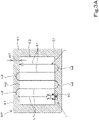
- the route preparation unit 51h refers to an agricultural field map MP registered in the storage unit 53, and prepares a travel route (planned travel route) L for automatic travel of the working machine 1 on the agricultural field map MP, as illustrated in FIG. 3A .
- the planned travel route L includes straight section(s) (straight route(s)) L1 on which the working machine 1 travels straight and turn section(s) (turn route(s)) L2 on which the working machine 1 turns.
- the straight section(s) L1 is/are mainly prepared in the work area E2, and the turn section(s) L2 is/are mainly prepared in the turn area E1.
- the range acquisition unit 51g acquires a front-rear work range w2 of the working device 2 (hereinafter referred to as second work dimension).
- the range acquisition unit 51g acquires the second work dimension w2 on the basis of information received by the input device.
- the second work dimension w2 of the working device 2 is a front-rear dimension over which the working device 2 does work against the ground such as an agricultural field, and is, for example, the largest front-rear dimension from the front edge to the rear edge of the range w2 where work is done by the working device 2.
- the working device 2 is a working device 2 that spreads a material onto the agricultural field such as a spreader
- the second work dimension w2 is a rearward spreading distance.
- the range acquisition unit 51g acquires the second work dimension w2 of a working device 2 other than a spreader which does fertilizer spreading work.
- the storage unit 53 stores the second work dimension w2 such that the second work dimension w2 is associated with the working device 2, and the range acquisition unit 51g is capable of acquiring the second work dimension w2 from the storage unit 53 on the basis of information acquired by the work acquisition unit 51e.
- the range acquisition unit 51g acquires a pre-set second work dimension w2 from the storage unit 53.
- the work dimension w2 may be pre-stored in the storage unit 53 such that the work dimension w2 is associated with its corresponding working device 2 and may be changeable as needed.
- the range acquisition unit 51g acquires a spreading work range w4 that is a range where spreading work is done by a spreader in a front-rear direction thereof, i.e., a rearward spreading distance w4 (hereinafter referred to as a second spreading dimension).
- the input screen M6 displayed on the display device 50 i.e., an input device, receives input of the second spreading dimension w4, and the storage unit 53 stores the second spreading dimension w4 such that the second spreading dimension w4 is associated with the spreader.
- the range acquisition unit 51g is capable of acquiring the second spreading dimension w4 from the storage unit 53 on the basis of the information about the working device 2 acquired by the work acquisition unit 51e.
- the range acquisition unit 51g acquires, from the storage unit 53, the second spreading dimension w4 which has been inputted into and received by the display device 50 and which is associated with the spreader.
- the work setting unit 51i sets work start position(s) STn and work end position(s) ETn for the working device 2.
- the work setting unit 51i sets the work start position(s) STn and the work end position(s) ETn for the spreader so that the work start position STn and the work end position(s) ETn are at different positions according to the spreading work range w4 acquired by the range acquisition unit 51g.
- the work setting unit 51i sets the work start position(s) STn and the work end position(s) ETn for the working device 2 on the planned travel route L according to the working device 2 linked to the linkage.
- the work setting unit 51i sets the work start position(s) ST n and the work end position(s) ETn on the basis of, for example, a boundary X1 between the work area E2 and the turn area E1. Furthermore, the work setting unit 51i sets the work start position(s) ST n and the work end position(s) ETn on the planned travel route L.
- the following description discusses, in detail, a screen displayed on the display unit 52 of the display device 50 and the acquisition of the reference distance Y1 by the information acquisition unit 51a.
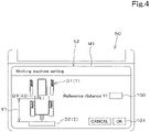
- the display device 50 displays, on the display unit 52, a reference setting screen M1 for input of information (for example, information about dimension(s) including the reference distance Y1) about the working machine 1, as illustrated in FIG. 4 .
- the reference setting screen M1 includes a shape D1 representing the working machine (tractor) 1, a shape D2 representing the working device 2, and a shape D3 representing the positioning device 40.
- the reference setting screen M1 includes a distance input section 100 for input of the reference distance Y1 and a first input confirmation button 101.
- the distance input section 100 is for input of the reference distance Y1.
- the reference distance Y1 is inputted by operating a predetermined operation item displayed in the reference setting screen M1, an operation switch on the display device 50, and/or the like.
- the first input confirmation button 101 is a piece of graphics via which operation to confirm the reference distance Y1 inputted into the distance input section 100 can be performed, i.e., via which operation to confirm the reception of the input of the reference distance Y1 can be performed.
- the storage unit 53 stores the reference distance Y1 inputted into the distance input section 100 such that the reference distance Y1 is associated with the working machine 1.
- the information acquisition unit 51a acquires the reference distance Y1 from the storage unit 53 on the basis of information acquired by the information acquisition unit 51a.
- the following description discusses, in detail, a screen displayed on the display unit 52 of the display device 50 and registration of a map by the map registration unit 51b.
- the display device 50 upon predetermined operation on the display device 50, the display device 50 displays a map registration screen M2 on the display unit 52.
- the map registration screen M2 displays a map MP1 including an agricultural field, machine body position(s) VP1 of the working machine 1, and agricultural field identification information such as the name of the agricultural filed, the identifier of the agricultural field, and/or the like.
- the map MP1 is associated with position information such as latitude and longitude in addition to image data representing the agricultural field.
- the map registration screen M2 displays the current machine body position(s) VP1 detected by the positioning device 40 when the working machine 1 was traveling around.
- a register button 105 displayed on the map registration screen M2 has been operated, as illustrated in FIG. 6A
- the map registration unit 51b uses, as an outline (outer edge) HI of the agricultural field, a traveled path K1 obtained from a plurality of machine body positions VP1 obtained when the working machine 1 was traveling around the agricultural field, and registers an agricultural field map MP defined by the outline HI together with the agricultural field identification information.
- the map registration unit 51b may register, as the outline HI (agricultural field map MP) of the agricultural field, an outline K2 connecting points of turn calculated from the traveled path indicated by the machine body positions VP1 as illustrated in FIG. 6B , and may register, as the outline HI (agricultural field map MP), an outline K3 connecting corners of an agricultural field designated by a driver or the like using a switch or the like on the working machine 1 when the working machine 1 travels around as illustrated in FIG. 6C .
- the above-described methods of registering the agricultural field are examples, and do not imply any limitation.
- the outline of the agricultural field, i.e., the agricultural field map MP may be data indicated by positions (latitude, longitude), may be data indicated by a coordination system (X axis, Y axis), and may be data indicated in some other manner.
- the storage unit 53 stores the agricultural field map MP which indicates the outline (contour) registered by the map registration unit 51b. That is, the storage unit 53 stores the agricultural field map MP, i.e., data indicating the outline of the agricultural field (data to represent a certain agricultural field).
- the following description discusses, in detail, a screen displayed on the display unit 52 of the display device 50, the acquisition of the width of the turn area E1 by the turn width acquisition unit 51c, and setting of the work area E2 by the area setting unit 51d.
- the display device 50 upon predetermined operation on the display device 50 by an operator (driver), the display device 50 displays an area setting screen M3 on the display unit 52.
- the area setting screen M3 includes an agricultural field input section 110, an agricultural field display section 111, a turn width input section 112, and a turn setting button 113.
- the agricultural field input section 110 is for input of agricultural field identification information such as the name of an agricultural field and the identifier of the agricultural field.
- the agricultural field display section 111 displays an agricultural field map MP representing a predetermined agricultural field corresponding to the agricultural field identification information inputted into the agricultural field input section 110. That is, the control unit 51 sends a request for an agricultural field map MP corresponding to the agricultural field identification information inputted into the agricultural field input section 110 to the storage unit 53, and causes the agricultural field map MP sent from the storage unit 53 to be displayed in the agricultural field display section 111.
- the turn width input section 112 is for input of the turn width W1 of a predetermined agricultural field corresponding to the agricultural field identification information inputted into the agricultural field input section 110.
- the turn setting button 113 is a piece of graphics via which operation to confirm the turn width W1 inputted into the turn width input section 112, i.e., confirm the reception of input of the turn width W1, can be performed.
- the turn width acquisition unit 51c acquires the turn width W1 inputted into the turn width input section 112.
- the area setting unit 51d causes the work area E2 excluding the turn area E1 to be displayed on the agricultural field map MP displayed in the agricultural field display section 111.
- the area setting unit 51d sets, as the work area E2, an area defined by an outline H2 that is offset inward from the outline H1 of the agricultural field map MP by the turn width W1 on the basis of the turn width W1 acquired by the turn width acquisition unit 51c.
- the work area E2 may be set on the agricultural field map MP by designating the position of the outline of the work area E2 using a pointer or the like on the agricultural field map MP displayed in the agricultural field display section 111 of the area setting screen M3.
- the storage unit 53 stores data of the agricultural field map MP on which the work area E2 is set, i.e., data indicating the position of the work area E2 on the agricultural field map MP.
- the following description discusses, in detail, a screen displayed on the display unit 52 of the display device 50 and the acquisition of the working device 2 or the work category or the like of the working device 2 by the work acquisition unit 51e.
- the display device 50 upon predetermined operation on the display device 50 by an operator (driver), the display device 50 displays a work selection screen M4 on the display unit 52.
- the work selection screen M4 includes a selection section 115.
- the selection section 115 enables operation of selection among a plurality of working devices 2 that can be attached to the working machine 1, i.e., operation to input identification information for identification of a working device 2 such as the name, model number, product number, and/or the like of the working device 2, work content of the working device 2 or the category thereof, and/or the like.
- the selection section 115 includes, for example, a plurality of selection members 116, and the plurality of selection members 116 are pieces of graphics associated with pieces of identification information for identification of working devices 2 such as the names, model numbers, or product numbers of the working devices 2 and/or the content of work done by the working devices 2 or categories thereof.
- the selection members 116 are associated with the work categories of the working devices 2, and the work categories associated with the plurality of selection members 116 at least include "fertilizer spreading", and, for example, the plurality of selection members 116 are associated with "cultivation", "puddling”, “stubble cultivation”, and “fertilizer spreading", respectively.
- the work category of a working device 2 is selected.
- the work categories associated with the plurality of selection members 116 may include, for example, “agricultural chemical spreading”, “watering”, “seeding”, “reaping”, and/or the like, and the categories are not limited to those described above.
- the work selection screen M4 includes a selection confirmation button 117.
- the selection confirmation button 117 is a piece of graphics which is operable. By selecting a work category of a working device 2 by operating one of the selection members 116 and operating the selection confirmation button 117, the selection of the work category of the working device 2 by operation of the selection member 116 is confirmed. Thus, once the selection confirmation button 117 has been operated, the work acquisition unit 51e acquires, from the storage unit 53, the work category associated with the selection member 116 which has been selected.
- the selection members 116 are associated with work categories and the work acquisition unit 51e acquires a work category from the storage unit 53 in the present embodiment
- the selection members 116 need only be associated with at least one of the identification information for identification of the working devices 2 such as the names, model numbers, or product numbers of the working devices 2, work content of the work devices 2, and the like, and the work acquisition unit 51e need only be capable of acquiring information which makes it possible to identify the working devices 2.
- the work acquisition unit 51e may acquire names or product numbers instead of the work categories.
- the following description discusses, in detail, a screen displayed on the display unit 52 of the display device 50, the acquisition of the first work dimension w1 by the work dimension acquisition unit 51f, the acquisition of the second work dimension w2 of the working device 2 by the range acquisition unit 51g, the preparation of the planned travel route L by the route preparation unit 51h, and setting of work start and work end for the working device 2 by the work setting unit 51i.
- the display device 50 displays a first settings screen M5 on the display unit 52 of the display device 50 as illustrated in FIG. 9A .
- the first settings screen M5 is an input screen for input of at least the second spreading dimension w4, and, on the basis of the inputted second spreading dimension w4, the work start position(s) ST n and the work end position(s) ETn can be set at different positions.
- the first settings screen M5 includes a route display section 120 in which a planned travel route L is displayed, a first dimension input section 121, a second dimension input section 122, and a second input confirmation button 123.
- the first dimension input section 121 is for input of the first spreading dimension w3 corresponding to the spreader which has been selected on the work selection screen M4.
- the second dimension input section 122 is for input of the second spreading dimension w4 corresponding to the spreader which has been selected on the work selection screen M4.
- the first spreading dimension w3 and the second spreading dimension w4 are each inputted by operating a predetermined operation item displayed on the first settings screen M5, an operation switch on the display device 50, and/or the like.
- the second input confirmation button 123 is a piece of graphics via which operation to confirm the first spreading dimension w3 inputted into the first dimension input section 121 and the second spreading dimension w4 inputted into the second dimension input section 122, that is, confirm the reception of input of the first spreading dimension w3 and the second spreading dimension w4, can be performed.
- the storage unit 53 stores the first spreading dimension w3 and the second spreading dimension w4 such that the first spreading dimension w3 and the second spreading dimension w4 are associated with the spreader.
- the work dimension acquisition unit 51f acquires the first spreading dimension w3 from the storage unit 53 on the basis of information acquired by the work acquisition unit 51e. Furthermore, the range acquisition unit 51g acquires the second spreading dimension w4 from the storage unit 53 on the basis of information acquired by the work acquisition unit 51e.
- the display device 50 displays a second settings screen M6 on the display unit 52.
- the second settings screen M6 is a screen which is for input of the first work dimension w1 and in which a planned travel route L can be set in the work area E2 on the basis of the inputted first work dimension w1.
- the second settings screen M6 includes a route display section 125 in which the planned travel route L is displayed, a third dimension input section 126, and a third input confirmation button 127.
- the third dimension input section 126 is for input of the first work dimension w1 corresponding to the working device 2 which has been selected on the work selection screen M4.
- the first work dimension w1 is inputted by operating a predetermined operation item displayed on the second settings screen M6, an operation switch on the display device 50, and/or the like.
- the third input confirmation button 127 is a piece of graphics via which operation to confirm the first work dimension w1 inputted into the third dimension input section 126, i.e., confirm the reception of input of the first work dimension w1, can be performed.
- the storage unit 53 stores the first work dimension w1 such that the first work dimension w1 is associated with the working device 2.
- the work dimension acquisition unit 51f acquires the first work dimension w1 from the storage unit 53 on the basis of information acquired by the work acquisition unit 51e.
- the range acquisition unit 51g acquires a pre-set second work dimension w2 from the storage unit 53 on the basis of information acquired by the work acquisition unit 51e.
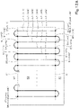
- the route preparation unit 51h divides the work area E2 into vertically or horizontally arranged areas each having the first work dimension w1 to prepare, in the work area E2, a plurality of unit work segments E3 in each of which work is to be done by the working device 2, as illustrated in FIG. 10A . That is, the route preparation unit 51h prepares a plurality of unit work segments E3 each of which has a width equal to the first work dimension w1 in the work area E2. Note that, as illustrated in FIG.
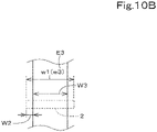
- the route preparation unit 51h may prepare, in the work area E2, a plurality of unit work segments E3 each having a width W3 obtained by excluding overlapping width(s) W2 from the first work dimension w1.
- the overlapping width W2 can be inputted on a predetermined screen displayed on the display unit 52. That is, the route preparation unit 51h sets, as each unit work segment E3, the smallest unit area in which work is done against the agricultural field by the working device 2 when the machine body 3 with the working device 2 linked thereto is caused to travel. Furthermore, as illustrated in FIG.
- the route preparation unit 51h may prepare, in the work area E2, a plurality of unit work segments E3 each having a width W5 obtained by adding underlapping width(s) W4 to the first work dimension w1.
- the underlapping width W4 can be inputted on a predetermined screen displayed on the display unit 52.
- the route preparation unit 51h prepares straight sections LI on which the machine body 3 travels straight for the respective unit work segments E3 of the agricultural field map MP That is, for example, the route preparation unit 51h prepares, in the widthwise middle portion of each unit work segment E3, a straight section L1 in the form of a continuous straight line which connects opposite ends of the unit work segment E3 in the lengthwise direction and which extends into, over, or across the turn area E1, the work area E2, and the boundary X1. Furthermore, the route preparation unit 51h prepares turn section(s) L2 connecting end portions of adjacent straight sections L1. That is, the route preparation unit 51h prepares the turn section(s) L2 at least in the turn area E1.
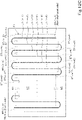
- the work setting unit 51i sets work start and work end for the working device 2. As illustrated in FIG. 12B , the work setting unit 51i sets work start position(s) ST n and work end position(s) ETn on the basis of the boundary X1 between the work area E2 and the turn area E1 and the second spreading dimension w4. The work setting unit 51i sets the work start position(s) ST n and the work end position(s) ETn on the planned travel route L.
- the work setting unit 51i sets a work start position ST n and a work end position ETn which are adjacent to each other so that the work start position ST n and the work end position ETn are at different positions in the front-rear direction of the machine body 3 (working device 2) according to at least the second spreading dimension w4.
- the work setting unit 51i sets the work start position ST n and the work end position ETn so that the work start position ST n and the work end position ETn are at different positions on the basis of the reference distance Y1 acquired by the information acquisition unit 51a and the second work dimension w2 (second spreading dimension w4) acquired by the range acquisition unit 51g.
- the work setting unit 51i in the present embodiment sets the work start position(s) ST n and the work end position(s) ETn so that the work start position(s) ST n and the work end position(s) ETn are at different positions on the basis of the reference distance Y1 acquired by the information acquisition unit 51a and the second work dimension w2 acquired by the range acquisition unit 51g
- the work setting unit 51i need only set the work start position(s) ST n and the work end position(s) ETn so that the work start position(s) ST n and the work end position(s) ETn are at different positions based at least on the second spreading dimension w4 acquired by the range acquisition unit 51g, and a method thereof is not limited to that described above.
- the work setting unit 51i may shift ends of the unit work segments E3 of the work area E2 into the turn area E1 by at least the second work dimension w2 and set the work start positions ST n and the work end positions ETn on the boundary X1 between the work area E2 and the turn area E1 (see FIG. 12C ).
- the working machine 1 includes a control device 60.
- the control device 60 is a device to control the traveling system of the working machine 1, control the working system of the working machine 1, and/or the like.
- the control device 60 has connected thereto an operation changeover switch 65.
- the operation changeover switch 65 is a switch capable of being switched between ON and OFF. When the operation changeover switch 65 is in the ON state, the control device 60 can be set to an automatic travel mode, and when the operation changeover switch 65 is in the OFF state, the control device 60 can be set to a manual operation mode.
- the control device 60 includes an automatic travel control unit 63.
- the automatic travel control unit 63 is composed of electric/electronic circuit(s) provided in the control device 60, program(s) stored in a CPU and/or the like in the control device 60, and/or the like.
- the automatic travel control unit 63 controls automatic travel of the machine body 3.
- the automatic travel control unit 63 starts the automatic travel when the working machine 1 is in an automatic travel mode. As illustrated in FIG. 13 , when the working machine 1 is performing automatic travel, if the deviation between the machine body position VP1 and the planned travel route L is less than a threshold, the automatic travel control unit 63 maintains the angle of rotation of the steering shaft (rotation shaft) 31. If the deviation between the machine body position VP1 and the planned travel route L is equal to or greater than the threshold and the working machine 1 is positioned leftward of the planned travel route L, the automatic travel control unit 63 causes the steering shaft 31 to rotate so that the working machine 1 is steered right.
- the automatic travel control unit 63 causes the steering shaft 31 to rotate so that the working machine 1 is steered left.
- the automatic travel control unit 63 may, in the case where the direction of the planned travel route L and the travel direction F1 of the working machine 1 (machine body 3) (machine body heading direction) differ from each other, i.e., in the case where an angle of the machine body heading direction F1 to the planned travel route L is equal to or greater than a threshold, set the angle of steering so that the angle is zero (the machine body heading direction F1 matches the direction of the planned travel route L).
- the automatic travel control unit 63 may set the final angle of steering for the automatic travel on the basis of an angle of steering determined based on the deviation (deviation in position) and an angle of steering determined based on the direction (deviation in direction) F1.
- Settings of the angle of steering in automatic travel in the above-described embodiment are examples, and do not imply any limitation.
- the automatic travel control unit 63 automatically changes the speed stage of the transmission 5, the speed of rotation of the prime mover 4, and/or the like so that the current speed of the working machine 1 matches the vehicle speed that corresponds to the planned travel route L.
- the control device 60 controls the working device 2 according to the work start position(s) ST n and the work end position(s) ETn set by the work setting unit 51i.
- the automatic travel control unit 63 of the control device 60 controls the working device 2 on the basis of the work start position(s) ST n and the work end position(s) ETn set by the work setting unit 51i, the position(s) of the machine body 3 measured by the positioning device 40, and the reference distance Y1.
- the automatic travel control unit 63 starts driving the working device 2 by outputting a start signal to a driving device (drive motor) of the working device 2, and stops the driving by outputting a stop signal.
- the automatic travel control unit 63 starts driving the working device 2 (causes the working device 2 to start doing work) when, under the conditions in which the working machine 1 is traveling while performing automatic travel at least along a turn section L2, the working device 2 has passed through a work start position ST n .
- the automatic travel control unit 63 stops driving the working device 2 (causes the working device 2 to stop doing the work) when, under the conditions in which the working machine 1 is traveling while performing automatic travel at least along the turn section L2, the working device 2 has passed through a work end position ETn.
- control device 60 need only cause the working device 2 to start doing work when the working device 2 linked to the linkage has passed through a work start position ST n and causes the working device 2 to stop doing the work when the working device 2 has passed through a work end position ETn, and a method of such control is not limited to that described above.
- the control device 60 (automatic travel control unit 63) starts the driving by outputting a start signal to a drive motor and stops the driving by outputting a stop signal.
- the control device 60 need only be capable of controlling starting and stopping of the driving of the working device 2, and may control the starting and stopping of the driving of the driving device by, for example, controlling a PTO clutch 155 (which is capable of switching between a connected state in which power from the PTO shaft is transmitted to the working device 2 and a disconnected state in which the power is not transmitted to the working device 2) to switch the connected state to the disconnected state. Any method of controlling the starting and stopping of the driving of the working device 2 may be used.
- a working machine 1 as has been described includes a machine body 3, a linkage capable of linking a working device 2 to the machine body 3, a spreader being one of types of the working device 2, an automatic travel control unit 63 to cause the machine body 3 to perform automatic travel according to a planned travel route L, a range acquisition unit 51g to acquire a spreading work range w4 that is a range where spreading work is done by the spreader in a front-rear direction thereof, and a work setting unit 51i to set a work start position ST n and a work end position ETn for the spreader so that the work start position ST n and the work end position ETn are at different positions according to the spreading work range w4 acquired by the range acquisition unit 51g.
- the configuration makes it possible to change the position at which work is started and the position at which the work is ended according to the spreading work range w4 that is a range where spreading work is done by the spreader in the front-rear direction.
- This makes it possible to do work at intended positions even in cases of a fertilizer spreader, an agricultural chemical spreader, a water spreader, or the like which differ relatively greatly in front-rear work range w2 compared to other working devices 2, and possible to prevent or reduce unevenness of fertilizer spreading and reduce unplowed land.
- the working machine 1 further includes an input device to receive input of the spreading work range w4 such that the spreading work range w4 is associated with the spreader, wherein the range acquisition unit 51g acquires the spreading work range w4 received by the input device.
- the range acquisition unit 51g acquires the spreading work range w4 received by the input device.
- the working machine 1 further includes a storage unit 53 to store the spreading work range w4 received by the input device, wherein the input device is a display device 50 to display an input screen M5 to receive input of the spreading work range w4, and the storage unit 53 stores the spreading work range w4 inputted into and received by the input screen M5 and the spreader corresponding to the spreading work range w4 such that the spreading work range w4 and the spreader are associated with each other.
- the storage unit 53 stores the spreading work range w4 and the spreader such that the spreading work range w4 and the spreader are associated with each other, and therefore the working machine 1 is capable of reading out the spreading work range w4 corresponding to the spreader. This eliminates the need for inputting the spreading work range w4 by operating the input device every time work is to be done.
- the working machine 1 further includes a storage unit 53 to store the spreading work range w4 received by the input device, wherein the storage unit 53 stores another type of the working device 2 other than the spreader and a pre-set work range w2 such that the other type of the working device 2 and the pre-set work range w2 are associated with each other, the range acquisition unit 51g acquires, if the working device 2 linked to the linkage is the spreader, the spreading work range w4 inputted into and received by the input device and associated with the spreader from the storage unit 53, and acquires, if the working device 2 linked to the linkage is the other type of the working device 2 other than the spreader, the work range w2 from the storage unit 53, and the work setting unit 51i sets the work start position ST n and the work end position ETn for the working device 2 linked to the linkage so that the work start position ST n and the work end position ETn are at different positions according to the spreading work range w4 or the work range w2 acquired by the range acquisition unit 51g.
- the work setting unit 51i is capable of, if the working device 2 is not a spreader, setting the work start position ST n and the work end position ETn according to a predetermined work range w2.
- the working device 2 is other than working devices 2 such as a fertilizer spreader, an agricultural chemical spreader and a water spreader which greatly vary in spreading work range w4 (work range w2) depending on the type of work or the type of working machine 1, the work start position ST n and the work end position ETn are set according to the pre-set work range w2.
- the working device 2 is not a spreader such as a fertilizer spreader, an agricultural chemical spreader, or a water spreader, the input device does not need to be operated, making it possible to improve efficiency and improve usability of the working machine 1.
- the working machine 1 further includes a control device 60 to control the working device 2 linked to the linkage according to the work start position ST n and the work end position ETn set by the work setting unit 51i, wherein the control device 60 causes the working device 2 linked to the linkage to start doing work when the working device 2 has passed through the work start position ST n and causes the working device 2 to stop doing the work when the working device 2 has passed through the work end position ETn.
- the working device 2 starts doing work at the work start position ST n set by the work setting unit 51i, and the working device 2 ends the work at the work end position ET n set by the work setting unit 51i, making it possible for the working machine 1 to do work at intended places.
- the working machine 1 further includes a route preparation unit 51h to prepare the planned travel route L, wherein the work setting unit 51i sets, according to the working device 2 linked to the linkage, the work start position ST n and the work end position ETn for the working device 2 on the planned travel route L.
- the work start position STn and the work end position ETn are set on the planned travel route L and therefore work is started and ended based on the position of the working machine 1, it is easy to cause the working machine 1 to travel and the working device 2 to do work in a linked manner, making it possible for the working machine 1 to do work more efficiently.
Landscapes
- Life Sciences & Earth Sciences (AREA)
- Engineering & Computer Science (AREA)
- Soil Sciences (AREA)
- Environmental Sciences (AREA)
- Mechanical Engineering (AREA)
- Remote Sensing (AREA)
- Aviation & Aerospace Engineering (AREA)
- Radar, Positioning & Navigation (AREA)
- Water Supply & Treatment (AREA)
- Physics & Mathematics (AREA)
- General Physics & Mathematics (AREA)
- Automation & Control Theory (AREA)
- Guiding Agricultural Machines (AREA)
- Control Of Position, Course, Altitude, Or Attitude Of Moving Bodies (AREA)
- Agricultural Machines (AREA)
- Fertilizing (AREA)
Abstract
Description
- The present invention relates to a working machine having a working device linked thereto.
- The technique disclosed in
Patent document 1 is known as a technique to prepare a travel route (work/travel line) for automatic travel of a working machine such as tractor. A working vehicle (working machine) ofPatent document 1 includes an acquiring unit to acquire position data of an outer periphery of an agricultural field, and a work setting unit to set, on the basis of the position data, a work/travel line for travel of a travel machine body (machine body) in the agricultural field. - [Patent document 1]
Japanese Unexamined Patent Application Publication No. 2018-39 - In
Patent document 1, a work/travel line (planned travel route) can be prepared and work can be done while automatic travel is performed along the work/travel line. However, when the working device is a spreader such as a fertilizer spreader or an agricultural chemical spreader, since a work range in a front-rear direction differs depending on the category of work done by the working device, some areas may be left with no work done and work efficiency may decrease. - The present invention was made in order to solve such an issue of the conventional technique, and an object thereof is to provide a working machine that is capable of accurately and efficiently doing work at intended positions.
- A working machine according to an aspect of the present invention includes a machine body, a linkage capable of linking a working device to the machine body, a spreader being one of types of the working device, an automatic travel control unit to cause the machine body to perform automatic travel according to a planned travel route, a range acquisition unit to acquire a spreading work range that is a range where spreading work is done by the spreader in a front-rear direction thereof, and a work setting unit to set a work start position and a work end position for the spreader so that the work start position and the work end position are at different positions according to the spreading work range acquired by the range acquisition unit.
- The working machine further includes an input device to receive input of the spreading work range such that the spreading work range is associated with the spreader, wherein the range acquisition unit acquires the spreading work range received by the input device.
- The working machine further includes a storage unit to store the spreading work range received by the input device, wherein the input device is a display device to display an input screen to receive input of the spreading work range, and the storage unit stores the spreading work range inputted into and received by the input screen and the spreader corresponding to the spreading work range such that the spreading work range and the spreader are associated with each other.
- The working machine further includes a storage unit to store the spreading work range received by the input device, wherein the storage unit stores another type of the working device other than the spreader and a pre-set work range such that the other type of the working device and the pre-set work range are associated with each other, the range acquisition unit acquires, if the working device linked to the linkage is the spreader, the spreading work range inputted into and received by the input device and associated with the spreader from the storage unit, and acquires, if the working device linked to the linkage is the other type of the working device other than the spreader, the work range from the storage unit; and the work setting unit sets the work start position and the work end position for the working device linked to the linkage so that the work start position and the work end position are at different positions according to the spreading work range or the work range acquired by the range acquisition unit.
- The working machine further includes a control device to control the working device linked to the linkage according to the work start position and the work end position set by the work setting unit, wherein the control device causes the working device linked to the linkage to start doing work when the working device has passed through the work start position and causes the working device to stop doing the work when the working device has passed through the work end position.
- The working machine further includes a route preparation unit to prepare the planned travel route, wherein the work setting unit sets, according to the working device linked to the linkage, the work start position and the work end position for the working device on the planned travel route.
- The above-described working machine is capable of accurately and efficiently doing work at intended positions.
-
-
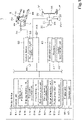
FIG. 1 shows a block diagram of a working machine. -
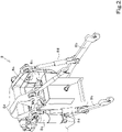
FIG. 2 illustrates a raising/lowering device. -
FIG. 3A illustrates an agricultural field map and a planned travel route. -
FIG. 3B illustrates a work range. -
FIG. 3C illustrates a spreading work range. -
FIG. 4 illustrates an example of a reference setting screen. -
FIG. 5 illustrates an example of a map registration screen. -
FIG. 6A illustrates how an outline of an agricultural field (agricultural field map) is determined from a traveled path. -
FIG. 6B illustrates how an outline of an agricultural field (agricultural field map) is determined from points of turn on a traveled path. -
FIG. 6C illustrates how an outline (agricultural field map) is determined from switch operations during travel. -
FIG. 7 illustrates an example of an area setting screen. -
FIG. 8 illustrates an example of a work selection screen. -
FIG. 9A illustrates an example of a first settings screen. -
FIG. 9B illustrates an example of a second settings screen. -
FIG. 10A is a diagram in which unit work segments are prepared in a work area. -
FIG. 10B illustrates a unit work segment differing from those ofFIG. 10A . -
FIG. 10C illustrates a unit work segment differing from those ofFIGS. 10A and10B . -
FIG. 11 illustrates how a planned travel route is prepared. -
FIG. 12A is a first diagram illustrating setting of work start positions and work end positions by a work setting unit. -
FIG. 12B is a second diagram illustrating setting of work start positions and work end positions by the work setting unit. -
FIG. 12C is a third diagram illustrating setting of work start positions and work end positions by the work setting unit. -
FIG. 13 illustrates an example of automatic travel. -
FIG. 14 is a general side view of the working machine. - The following description discusses an embodiment of the present invention with reference to drawings.
-
FIG. 14 illustrates a tractor, which is an example of aworking machine 1. The workingmachine 1 is discussed using a tractor as an example, but theworking machine 1 is not limited to a tractor and may be a rice transplanter or a combine. In embodiments of the present invention, descriptions are based on the assumption that the front of theworking machine 1 as seen from an operator (driver) seated on an operator's seat 10 (indicated by arrow A1 inFIGS. 3B ,3C , and14 ) is "front", the rear of the workingmachine 1 as seen from the operator is "rear" (indicated by arrow A2 inFIGS. 3B ,3C , and14 ), the left side of the workingmachine 1 as seen from the operator is "left" (near side inFIG. 14 , indicated byarrow B 1 inFIGS. 3B and3C ), and the right side of the workingmachine 1 as seen from the operator is "right" (far side inFIG. 14 , indicated by arrow B2 inFIGS. 3B and3C ). The descriptions are also based on the assumption that a horizontal direction orthogonal to a front-rear direction of the workingmachine 1 is a width direction. - As illustrated in
FIG. 14 , the workingmachine 1 includes: a machine body (travel vehicle body) 3 with a travelingdevice 7; aprime mover 4; and atransmission 5. The travelingdevice 7 includes front wheel(s) 7F and rear wheel(s) 7R. Thefront wheels 7F may be tire-shaped wheels and may be crawler-shaped wheels. Therear wheels 7R also may be tire-shaped wheels and may be crawler-shaped wheels. Theprime mover 4 is a diesel engine, an electric motor, and/or the like. Thetransmission 5 is capable of changing driving forces for the travelingdevice 7 by changing speed stages and switching the traveling state of the travelingdevice 7 between forward and rearward traveling states. Themachine body 3 is provided with acabin 9, and thecabin 9 is provided with the operator'sseat 10 therein. - The
machine body 3 is provided with a linkage at the rear thereof. The linkage is a swinging drawbar which connects a workingdevice 2 and themachine body 3 but does not raise or lower the workingdevice 2, a raising/loweringdevice 8 which is composed of a three-point linkage or the like and which raises and lowers the workingdevice 2, or the like. The workingdevice 2 can be attached to and detached from the linkage. By linking the workingdevice 2 to the linkage, it is possible for themachine body 3 to tow the workingdevice 2. Examples of the workingdevice 2 at least include spreaders. Examples of the spreaders include a fertilizer spreader (broadcaster), an agricultural chemical spreader for spreading agricultural chemicals, a water spreader for spreading water, and the like. Examples of the working device further include a cultivator for cultivation, a transplanter for planting, a mower for mowing grass or the like, a tedder for tedding grass or the like, a rake for raking grass or the like, a baler for baling grass or the like, and the like, in addition to the above-described spreaders. Note that the following description discusses an example case in which a fertilizer spreader as a spreader is linked to the linkage. - As illustrated in
FIGS. 1 and2 , the raising/loweringdevice 8 includes liftarms 8a,lower links 8b, atop link 8c,lift rods 8d, and liftcylinders 8e. A front end of eachlift arm 8a is supported on an upper rear portion of a case (transmission case) housing thetransmission 5 such that thelift arm 8a is swingable up and down. Thelift arm 8a is driven by acorresponding lift cylinder 8e to swing (raised or lowered). Thelift cylinder 8e is composed of a hydraulic cylinder. Thelift cylinder 8e is connected to a hydraulic pump via acontrol valve 36. Thecontrol valve 36 is a solenoid valve or the like to cause thelift cylinder 8e to extend and retract. - As illustrated in
FIG. 1 , a front end of eachlower link 8b is supported on a lower rear portion of thetransmission 5 such that thelower link 8b is swingable up and down. A front end of thetop link 8c is supported, at a position higher than thelower link 8b, on a rear portion of thetransmission 5 such that thetop link 8c is swingable up and down. Eachlift rod 8d connects acorresponding lift arm 8a and a correspondinglower link 8b. The workingdevice 2 is linked to rear portions of thelower links 8b and thetop link 8c. When thelift cylinders 8e are driven (extend or retract), thelift arms 8a ascend or descend, and thelower links 8b connected to thelift arms 8a via thelift rods 8d also ascend or descend. With this, the workingdevice 2 swings up or down (raised or lowered) about front portions of thelower links 8b. - As illustrated in
FIG. 1 , the workingmachine 1 includes asteering unit 29. Thesteering unit 29 includes asteering wheel 30, a rotation shaft (steering shaft) 31 which rotates as thesteering wheel 30 rotates, and an assist mechanism (power steering mechanism) 32 to assist steering performed using thesteering wheel 30. Theassist mechanism 32 includes ahydraulic pump 33, acontrol valve 34 supplied with hydraulic fluid discharged from thehydraulic pump 33, and asteering cylinder 35 which is actuated by thecontrol valve 34. Thecontrol valve 34 is a solenoid valve which is actuated according to a control signal. Thecontrol valve 34 is, for example, a three-way switching valve which achieves multi-position switching by movement of a spool or the like. The positions of thecontrol valve 34 can also be switched by steering by the steeringshaft 31. Thesteering cylinder 35 is connected to arms (knuckle arms) which change the orientation of thefront wheels 7F. - Therefore, upon operation of the
steering wheel 30, the position and the degree of opening of thecontrol valve 34 change according to thesteering wheel 30, and thesteering cylinder 35 extends or retracts leftward or rightward according to the position and the degree of opening of thecontrol valve 34, making it possible to change the steering direction of thefront wheels 7F. Note that the foregoingsteering unit 29 is an example, and the foregoing configuration does not imply limitation. - As illustrated in
FIG. 1 , the workingmachine 1 includes apositioning device 40. Thepositioning device 40 is capable of detecting the position thereof (measured position information including latitude and longitude) by a satellite positioning system (positioning satellites) such as D-GPS, GPS, GLONASS, BeiDou, Galileo, and/or Michibiki. Specifically, thepositioning device 40 receives satellite signals (positions of positioning satellites, time of transmission, correction information, and/or the like) from the positioning satellites, and detects the position (e.g., latitude and longitude) of the workingmachine 1, i.e., a machine body position VP1, on the basis of the satellite signals. Thepositioning device 40 includes areceiver 41 and an inertial measurement unit (IMU) 42. Thereceiver 41 is a device which includes an antenna and/or the like and which receives satellite signals from the positioning satellites, and is attached to themachine body 3 separately from theinertial measurement unit 42. In the present embodiment, thereceiver 41 is attached to themachine body 3, e.g., thecabin 9. Note that the location at which thereceiver 41 is attached is not limited to those described in embodiments. - The
inertial measurement unit 42 includes an acceleration sensor to detect acceleration, a gyroscope sensor to detect angular velocity, and/or the like. Theinertial measurement unit 42 is provided on themachine body 3, for example, below the operator'sseat 10, and is capable of detecting the roll angle, pitch angle, yaw angle, and/or the like of themachine body 3. - As illustrated in
FIG. 1 , the workingmachine 1 includes an input device. The input device is a device to receive various settings regarding the workingmachine 1. The input device is, for example, adisplay device 50 which is operable and which displays predetermined input screens M5 and M6 to receive input of settings, a switch via which the operation of inputting settings can be performed, and/or the like. In the present embodiment, the input device is, for example, thedisplay device 50 of the workingmachine 1. Thedisplay device 50 includes acontrol unit 51, adisplay unit 52, and astorage unit 53. Thecontrol unit 51 is composed of a CPU, electric/electronic circuit(s), and/or the like, and performs various control regarding thedisplay device 50. Thedisplay unit 52 is operable, is composed of a panel or the like such as a liquid crystal panel, a touchscreen, and/or the like, and displays various information regarding the workingmachine 1. - The
storage unit 53 is composed of nonvolatile memory(memories) and/or the like. Thestorage unit 53 stores, for example, application program(s) for assisting work and/or the like done by the workingmachine 1, and, upon startup of the application program(s), thedisplay device 50 functions as a work assistance device to assist work. Note that, also when thedisplay device 50 functions as a work assistance device, processing that thedisplay device 50 as the work assistance device performs is performed by thecontrol unit 51 which is hardware. - As illustrated in
FIG. 1 , the workingmachine 1 includes aninformation acquisition unit 51a, amap registration unit 51b, a turnwidth acquisition unit 51c, anarea setting unit 51d, awork acquisition unit 51e, a workdimension acquisition unit 51f, arange acquisition unit 51g, aroute preparation unit 51h, and awork setting unit 51i. In the present embodiment, thedisplay device 50 includes theinformation acquisition unit 51a, themap registration unit 51b, the turnwidth acquisition unit 51c, thearea setting unit 51d, thework acquisition unit 51e, the workdimension acquisition unit 51f, therange acquisition unit 51g, theroute preparation unit 51h, and thework setting unit 51i. Theinformation acquisition unit 51a, themap registration unit 51b, the turnwidth acquisition unit 51c, thearea setting unit 51d, thework acquisition unit 51e, the workdimension acquisition unit 51f, therange acquisition unit 51g, theroute preparation unit 51h, and thework setting unit 51i are each composed of electric/electronic circuit(s) of thecontrol unit 51 of thedisplay device 50, program(s) stored in a CPU and/or the like of thecontrol unit 51, and/or the like. Note that, in the present embodiment, theinformation acquisition unit 51a, themap registration unit 51b, the turnwidth acquisition unit 51c, thearea setting unit 51d, thework acquisition unit 51e, the workdimension acquisition unit 51f, therange acquisition unit 51g, theroute preparation unit 51h, and thework setting unit 51i are composed of thecontrol unit 51, but may be composed of electric/electronic circuit(s) and/or the like other than thecontrol unit 51, and may be composed of, for example, acontrol device 60 of the workingmachine 1. - The
information acquisition unit 51a acquires information regarding relative positions of themachine body 3 and the workingdevice 2. Theinformation acquisition unit 51a acquires information inputted into thedisplay device 50. Specifically, theinformation acquisition unit 51a acquires a reference distance Y1 which is the distance from a predetermined position on themachine body 3 to a predetermined position on the workingdevice 2. For example, as illustrated inFIG. 3B and3C , the reference distance Y1 is the distance between thepositioning device 40 and a front edge of a work range of the workingdevice 2 in the front-rear direction (direction of travel). - Note that the reference distance need only be a reference for calculation of the relative positions of the
machine body 3 and the workingdevice 2. The reference distance may be the distance between thepositioning device 40 and a rear edge of the linkage (raising/lowering device 8) (i.e., front portion of the working device 2) in the front-rear direction (direction of travel), and may be the distance from a rear edge of themachine body 3 to a front edge of a work range w2 of the workingdevice 2. - Furthermore, the
information acquisition unit 51a need only acquire information regarding the relative positions of themachine body 3 and the workingdevice 2, and the information is not limited to information inputted into the input device (display device 50). Information regarding the relative positions of themachine body 3 and the workingdevice 2 may be pre-stored in thestorage unit 53 and theinformation acquisition unit 51a may acquire the information regarding the relative positions of themachine body 3 and the workingdevice 2 from thestorage unit 53. - The
map registration unit 51b registers an agricultural field map MP of a certain agricultural field, for example, registers positions corresponding to the outline of a certain agricultural field. Themap registration unit 51b acquires position information of the outline of the agricultural field on the basis of, for example, machine body position(s) VP1 detected by thepositioning device 40 of the workingmachine 1, and stores the position information and the agricultural field in thestorage unit 53 such that the position information and the agricultural field are associated with each other. Note that themap registration unit 51b need only be capable of registering agricultural field map(s) MP of certain agricultural field(s), and, for example, may externally acquire agricultural field map(s) MP via wireless or wired communication or a storage medium and register the agricultural field map(s) MP A method of registering agricultural field map(s) MP is not limited to the above-described method. - The turn
width acquisition unit 51c acquires a width (turn width) W1 of a turn area E1 which is an area where themachine body 3 makes a turn. The turn area E1 is, for example, an area including a footpath and its surrounding area. The turnwidth acquisition unit 51c acquires the turn width W1 by acquiring information inputted into the input device (display device 50) via thestorage unit 53. - The
area setting unit 51d sets an area in which the workingdevice 2 does work as illustrated inFIG. 3A , that is, a work area E2 which is the agricultural field map MP excluding the turn area E1, on the agricultural field map MP Thearea setting unit 51d sets the work area E2 on the basis of the turn width W1 acquired by the turnwidth acquisition unit 51c. Thearea setting unit 51d registers the work area E2 on the agricultural field map MP stored in thestorage unit 53. Thearea setting unit 51d sets, as the work area E2, an area defined by an outline H2 that is offset inward from the outline HI of the agricultural field map MP by the turn width W1. - Note that the
area setting unit 51d need only be capable of setting the work area E2. For example, thearea setting unit 51d may set the work area E2 on the agricultural field map MP upon designation of the position of the outline of the work area E2 by a pointer or the like on the agricultural field map MP displayed on thedisplay unit 52 of thedisplay device 50. A method thereof is not limited to the method as described above. - The
work acquisition unit 51e acquires the workingdevice 2 attached to the linkage (raising/lowering device 8), work content (work category) of the workingdevice 2, and/or the like. Thework acquisition unit 51e acquires the workingdevice 2, the work content, and/or the like by acquiring information inputted into the input device (display device 50) via thestorage unit 53. For example, thestorage unit 53 stores therein a plurality of workingdevices 2 that can be attached to the workingmachine 1, i.e., identification information for identification of the workingdevices 2 such as the names, model numbers, product numbers, and/or the like of the workingdevices 2, work content of each of the workingdevices 2, the categories thereof, and/or the like, and thework acquisition unit 51e acquires acorresponding working device 2 or work content of the workingdevice 2 stored in thestorage unit 53 on the basis of the information inputted into the input device. - The work
dimension acquisition unit 51f acquires a widthwise work range w1 of the working device 2 (a widthwise work range w1 of a spreader is particularly referred to as a widthwise spreading work range w3). As illustrated inFIGS. 3B and3C , the widthwise work range w1 of the working device 2 (hereinafter referred to as a first work dimension) is a width over which the workingdevice 2 does work against the ground such as an agricultural filed (width over which work is done). Furthermore, the first work dimension w1 is, for example, the greatest widthwise dimension of the range where work is done by the workingdevice 2. - As illustrated in
FIG. 3C , in the case where the workingdevice 2 is a workingdevice 2 that spreads a material onto the agricultural field such as a fertilizer spreader, the first work dimension w1, i.e., the widthwise spreading work range (hereinafter referred to as a first spreading dimension) w3, is a width over which fertilizer spreading is performed, and the first spreading dimension w3 can be changed by controlling, for example, an opening angle of a shutter for passage of fertilizer by operating the fertilizer spreader. The first spreading dimension w3 varies depending on the particle size of the fertilizer. Specifically, as the particle size of the fertilizer to be spread by the fertilizer spreader increases, the first spreading dimension w3 decreases, whereas, as the particle size of the fertilizer decreases, the first spreading dimension w3 increases. - The work
dimension acquisition unit 51f acquires the first work dimension w1 on the basis of information received by thedisplay device 50. Specifically, input screen(s) M5 and/or M6 displayed on thedisplay device 50, i.e., an input device, receives input of the first work dimension w1, and thestorage unit 53 stores the first work dimension w1 such that the first work dimension w1 is associated with acorresponding working device 2. The workdimension acquisition unit 51f is capable of acquiring the first work dimension w1 from thestorage unit 53 on the basis of the information acquired by thework acquisition unit 51e. - The
route preparation unit 51h refers to an agricultural field map MP registered in thestorage unit 53, and prepares a travel route (planned travel route) L for automatic travel of the workingmachine 1 on the agricultural field map MP, as illustrated inFIG. 3A . The planned travel route L includes straight section(s) (straight route(s)) L1 on which the workingmachine 1 travels straight and turn section(s) (turn route(s)) L2 on which the workingmachine 1 turns. The straight section(s) L1 is/are mainly prepared in the work area E2, and the turn section(s) L2 is/are mainly prepared in the turn area E1. - The
range acquisition unit 51g acquires a front-rear work range w2 of the working device 2 (hereinafter referred to as second work dimension). Therange acquisition unit 51g acquires the second work dimension w2 on the basis of information received by the input device. As illustrated inFIGS. 3B and3C , the second work dimension w2 of the workingdevice 2 is a front-rear dimension over which the workingdevice 2 does work against the ground such as an agricultural field, and is, for example, the largest front-rear dimension from the front edge to the rear edge of the range w2 where work is done by the workingdevice 2. Note that, when the workingdevice 2 is a workingdevice 2 that spreads a material onto the agricultural field such as a spreader, the second work dimension w2 is a rearward spreading distance. - First, the following description discusses a case in which the
range acquisition unit 51g acquires the second work dimension w2 of a workingdevice 2 other than a spreader which does fertilizer spreading work. Thestorage unit 53 stores the second work dimension w2 such that the second work dimension w2 is associated with the workingdevice 2, and therange acquisition unit 51g is capable of acquiring the second work dimension w2 from thestorage unit 53 on the basis of information acquired by thework acquisition unit 51e. Thus, when the workingdevice 2 linked to the linkage is not a spreader such as a fertilizer spreader, an agricultural chemical spreader, a water spreader, or the like, therange acquisition unit 51g acquires a pre-set second work dimension w2 from thestorage unit 53. Note that, although the second work dimension w2 is pre-stored in thestorage unit 53 in the above embodiment, the work dimension w2 may be pre-stored in thestorage unit 53 such that the work dimension w2 is associated with itscorresponding working device 2 and may be changeable as needed. - Next, the following description discusses an example case in which the
range acquisition unit 51g acquires a spreading work range w4 that is a range where spreading work is done by a spreader in a front-rear direction thereof, i.e., a rearward spreading distance w4 (hereinafter referred to as a second spreading dimension). The input screen M6 displayed on thedisplay device 50, i.e., an input device, receives input of the second spreading dimension w4, and thestorage unit 53 stores the second spreading dimension w4 such that the second spreading dimension w4 is associated with the spreader. Therange acquisition unit 51g is capable of acquiring the second spreading dimension w4 from thestorage unit 53 on the basis of the information about the workingdevice 2 acquired by thework acquisition unit 51e. Thus, when the workingdevice 2 linked to the linkage is a spreader, therange acquisition unit 51g acquires, from thestorage unit 53, the second spreading dimension w4 which has been inputted into and received by thedisplay device 50 and which is associated with the spreader. - The
work setting unit 51i sets work start position(s) STn and work end position(s) ETn for the workingdevice 2. Thework setting unit 51i sets the work start position(s) STn and the work end position(s) ETn for the spreader so that the work start position STn and the work end position(s) ETn are at different positions according to the spreading work range w4 acquired by therange acquisition unit 51g. Thework setting unit 51i sets the work start position(s) STn and the work end position(s) ETn for the workingdevice 2 on the planned travel route L according to the workingdevice 2 linked to the linkage. Thework setting unit 51i sets the work start position(s) STn and the work end position(s) ETn on the basis of, for example, a boundary X1 between the work area E2 and the turn area E1. Furthermore, thework setting unit 51i sets the work start position(s) STn and the work end position(s) ETn on the planned travel route L. - The following description discusses, in detail, a screen displayed on the
display unit 52 of thedisplay device 50 and the acquisition of the reference distance Y1 by theinformation acquisition unit 51a. Upon predetermined operation on thedisplay device 50 by an operator, thedisplay device 50 displays, on thedisplay unit 52, a reference setting screen M1 for input of information (for example, information about dimension(s) including the reference distance Y1) about the workingmachine 1, as illustrated inFIG. 4 . The reference setting screen M1 includes a shape D1 representing the working machine (tractor) 1, a shape D2 representing the workingdevice 2, and a shape D3 representing thepositioning device 40. The reference setting screen M1 includes adistance input section 100 for input of the reference distance Y1 and a firstinput confirmation button 101. - The
distance input section 100 is for input of the reference distance Y1. The reference distance Y1 is inputted by operating a predetermined operation item displayed in the reference setting screen M1, an operation switch on thedisplay device 50, and/or the like. - The first
input confirmation button 101 is a piece of graphics via which operation to confirm the reference distance Y1 inputted into thedistance input section 100 can be performed, i.e., via which operation to confirm the reception of the input of the reference distance Y1 can be performed. Thus, upon input of the reference distance Y1 into thedistance input section 100 and operation of the firstinput confirmation button 101, thestorage unit 53 stores the reference distance Y1 inputted into thedistance input section 100 such that the reference distance Y1 is associated with the workingmachine 1. Theinformation acquisition unit 51a acquires the reference distance Y1 from thestorage unit 53 on the basis of information acquired by theinformation acquisition unit 51a. - The following description discusses, in detail, a screen displayed on the
display unit 52 of thedisplay device 50 and registration of a map by themap registration unit 51b. As illustrated inFIG. 5 , upon predetermined operation on thedisplay device 50, thedisplay device 50 displays a map registration screen M2 on thedisplay unit 52. The map registration screen M2 displays a map MP1 including an agricultural field, machine body position(s) VP1 of the workingmachine 1, and agricultural field identification information such as the name of the agricultural filed, the identifier of the agricultural field, and/or the like. The map MP1 is associated with position information such as latitude and longitude in addition to image data representing the agricultural field. Once the workingmachine 1 has entered the agricultural field and traveled around the agricultural field, the map registration screen M2 displays the current machine body position(s) VP1 detected by thepositioning device 40 when the workingmachine 1 was traveling around. Once the workingmachine 1 has traveled around the agricultural field and aregister button 105 displayed on the map registration screen M2 has been operated, as illustrated inFIG. 6A , themap registration unit 51b uses, as an outline (outer edge) HI of the agricultural field, a traveled path K1 obtained from a plurality of machine body positions VP1 obtained when the workingmachine 1 was traveling around the agricultural field, and registers an agricultural field map MP defined by the outline HI together with the agricultural field identification information. - Note that the
map registration unit 51b may register, as the outline HI (agricultural field map MP) of the agricultural field, an outline K2 connecting points of turn calculated from the traveled path indicated by the machine body positions VP1 as illustrated inFIG. 6B , and may register, as the outline HI (agricultural field map MP), an outline K3 connecting corners of an agricultural field designated by a driver or the like using a switch or the like on the workingmachine 1 when the workingmachine 1 travels around as illustrated inFIG. 6C . The above-described methods of registering the agricultural field are examples, and do not imply any limitation. The outline of the agricultural field, i.e., the agricultural field map MP, may be data indicated by positions (latitude, longitude), may be data indicated by a coordination system (X axis, Y axis), and may be data indicated in some other manner. - The
storage unit 53 stores the agricultural field map MP which indicates the outline (contour) registered by themap registration unit 51b. That is, thestorage unit 53 stores the agricultural field map MP, i.e., data indicating the outline of the agricultural field (data to represent a certain agricultural field). - The following description discusses, in detail, a screen displayed on the
display unit 52 of thedisplay device 50, the acquisition of the width of the turn area E1 by the turnwidth acquisition unit 51c, and setting of the work area E2 by thearea setting unit 51d. As illustrated inFIG. 7 , upon predetermined operation on thedisplay device 50 by an operator (driver), thedisplay device 50 displays an area setting screen M3 on thedisplay unit 52. The area setting screen M3 includes an agriculturalfield input section 110, an agriculturalfield display section 111, a turnwidth input section 112, and aturn setting button 113. The agriculturalfield input section 110 is for input of agricultural field identification information such as the name of an agricultural field and the identifier of the agricultural field. The agriculturalfield display section 111 displays an agricultural field map MP representing a predetermined agricultural field corresponding to the agricultural field identification information inputted into the agriculturalfield input section 110. That is, thecontrol unit 51 sends a request for an agricultural field map MP corresponding to the agricultural field identification information inputted into the agriculturalfield input section 110 to thestorage unit 53, and causes the agricultural field map MP sent from thestorage unit 53 to be displayed in the agriculturalfield display section 111. - The turn
width input section 112 is for input of the turn width W1 of a predetermined agricultural field corresponding to the agricultural field identification information inputted into the agriculturalfield input section 110. Theturn setting button 113 is a piece of graphics via which operation to confirm the turn width W1 inputted into the turnwidth input section 112, i.e., confirm the reception of input of the turn width W1, can be performed. Thus, upon input of the turn width W1 into the turnwidth input section 112 and operation of theturn setting button 113, the turnwidth acquisition unit 51c acquires the turn width W1 inputted into the turnwidth input section 112. - Furthermore, once the
turn setting button 113 has been selected and the turnwidth acquisition unit 51c has acquired the turn width W1 inputted into the turnwidth input section 112, thearea setting unit 51d causes the work area E2 excluding the turn area E1 to be displayed on the agricultural field map MP displayed in the agriculturalfield display section 111. For example, thearea setting unit 51d sets, as the work area E2, an area defined by an outline H2 that is offset inward from the outline H1 of the agricultural field map MP by the turn width W1 on the basis of the turn width W1 acquired by the turnwidth acquisition unit 51c. Note that the work area E2 may be set on the agricultural field map MP by designating the position of the outline of the work area E2 using a pointer or the like on the agricultural field map MP displayed in the agriculturalfield display section 111 of the area setting screen M3. - The
storage unit 53 stores data of the agricultural field map MP on which the work area E2 is set, i.e., data indicating the position of the work area E2 on the agricultural field map MP. - The following description discusses, in detail, a screen displayed on the
display unit 52 of thedisplay device 50 and the acquisition of the workingdevice 2 or the work category or the like of the workingdevice 2 by thework acquisition unit 51e. As illustrated inFIG. 8 , upon predetermined operation on thedisplay device 50 by an operator (driver), thedisplay device 50 displays a work selection screen M4 on thedisplay unit 52. The work selection screen M4 includes aselection section 115. Theselection section 115 enables operation of selection among a plurality of workingdevices 2 that can be attached to the workingmachine 1, i.e., operation to input identification information for identification of a workingdevice 2 such as the name, model number, product number, and/or the like of the workingdevice 2, work content of the workingdevice 2 or the category thereof, and/or the like. - As illustrated in
FIG. 8 , theselection section 115 includes, for example, a plurality ofselection members 116, and the plurality ofselection members 116 are pieces of graphics associated with pieces of identification information for identification of workingdevices 2 such as the names, model numbers, or product numbers of the workingdevices 2 and/or the content of work done by the workingdevices 2 or categories thereof. In the present embodiment, as illustrated inFIG. 8 , theselection members 116 are associated with the work categories of the workingdevices 2, and the work categories associated with the plurality ofselection members 116 at least include "fertilizer spreading", and, for example, the plurality ofselection members 116 are associated with "cultivation", "puddling", "stubble cultivation", and "fertilizer spreading", respectively. Thus, once operation to select any of the plurality ofselection members 116 has been performed, the work category of a workingdevice 2 is selected. Note that the work categories associated with the plurality ofselection members 116 may include, for example, "agricultural chemical spreading", "watering", "seeding", "reaping", and/or the like, and the categories are not limited to those described above. - Furthermore, as illustrated in
FIG. 8 , the work selection screen M4 includes aselection confirmation button 117. Theselection confirmation button 117 is a piece of graphics which is operable. By selecting a work category of a workingdevice 2 by operating one of theselection members 116 and operating theselection confirmation button 117, the selection of the work category of the workingdevice 2 by operation of theselection member 116 is confirmed. Thus, once theselection confirmation button 117 has been operated, thework acquisition unit 51e acquires, from thestorage unit 53, the work category associated with theselection member 116 which has been selected. - Note that, although the
selection members 116 are associated with work categories and thework acquisition unit 51e acquires a work category from thestorage unit 53 in the present embodiment, theselection members 116 need only be associated with at least one of the identification information for identification of the workingdevices 2 such as the names, model numbers, or product numbers of the workingdevices 2, work content of thework devices 2, and the like, and thework acquisition unit 51e need only be capable of acquiring information which makes it possible to identify the workingdevices 2. Thework acquisition unit 51e may acquire names or product numbers instead of the work categories. - The following description discusses, in detail, a screen displayed on the
display unit 52 of thedisplay device 50, the acquisition of the first work dimension w1 by the workdimension acquisition unit 51f, the acquisition of the second work dimension w2 of the workingdevice 2 by therange acquisition unit 51g, the preparation of the planned travel route L by theroute preparation unit 51h, and setting of work start and work end for the workingdevice 2 by thework setting unit 51i. - In the case where the operator (driver) has performed operation to select a working
device 2 on the work selection screen M4 and the workingdevice 2 acquired by thework acquisition unit 51e is a spreader that does fertilizer spreading work, agricultural chemical spreading work, water spreading work, or the like, thedisplay device 50 displays a first settings screen M5 on thedisplay unit 52 of thedisplay device 50 as illustrated inFIG. 9A . The first settings screen M5 is an input screen for input of at least the second spreading dimension w4, and, on the basis of the inputted second spreading dimension w4, the work start position(s) STn and the work end position(s) ETn can be set at different positions. Furthermore, in the first settings screen M5, the first spreading dimension w3 can be inputted, and the planned travel route L can be set in the work area E2 on the basis of the inputted first spreading dimension w3. The first settings screen M5 includes aroute display section 120 in which a planned travel route L is displayed, a firstdimension input section 121, a seconddimension input section 122, and a secondinput confirmation button 123. - The first
dimension input section 121 is for input of the first spreading dimension w3 corresponding to the spreader which has been selected on the work selection screen M4. The seconddimension input section 122 is for input of the second spreading dimension w4 corresponding to the spreader which has been selected on the work selection screen M4. The first spreading dimension w3 and the second spreading dimension w4 are each inputted by operating a predetermined operation item displayed on the first settings screen M5, an operation switch on thedisplay device 50, and/or the like. - The second
input confirmation button 123 is a piece of graphics via which operation to confirm the first spreading dimension w3 inputted into the firstdimension input section 121 and the second spreading dimension w4 inputted into the seconddimension input section 122, that is, confirm the reception of input of the first spreading dimension w3 and the second spreading dimension w4, can be performed. Thus, once the first spreading dimension w3 has been inputted into the firstdimension input section 121, the second spreading dimension w4 has been inputted into the seconddimension input section 122, and the secondinput confirmation button 123 has been selected, thestorage unit 53 stores the first spreading dimension w3 and the second spreading dimension w4 such that the first spreading dimension w3 and the second spreading dimension w4 are associated with the spreader. The workdimension acquisition unit 51f acquires the first spreading dimension w3 from thestorage unit 53 on the basis of information acquired by thework acquisition unit 51e. Furthermore, therange acquisition unit 51g acquires the second spreading dimension w4 from thestorage unit 53 on the basis of information acquired by thework acquisition unit 51e. - In the case where the operator (driver) has performed operation to select a working
device 2 on the work selection screen M4 and the workingdevice 2 acquired by thework acquisition unit 51e is a workingdevice 2 other than spreaders such as a fertilizer spreader, an agricultural chemical spreader, and a water spreader, as illustrated inFIG. 9B , thedisplay device 50 displays a second settings screen M6 on thedisplay unit 52. The second settings screen M6 is a screen which is for input of the first work dimension w1 and in which a planned travel route L can be set in the work area E2 on the basis of the inputted first work dimension w1. The second settings screen M6 includes aroute display section 125 in which the planned travel route L is displayed, a thirddimension input section 126, and a thirdinput confirmation button 127. - The third
dimension input section 126 is for input of the first work dimension w1 corresponding to the workingdevice 2 which has been selected on the work selection screen M4. The first work dimension w1 is inputted by operating a predetermined operation item displayed on the second settings screen M6, an operation switch on thedisplay device 50, and/or the like. - The third
input confirmation button 127 is a piece of graphics via which operation to confirm the first work dimension w1 inputted into the thirddimension input section 126, i.e., confirm the reception of input of the first work dimension w1, can be performed. Thus, upon input of the first work dimension w1 into the thirddimension input section 126 and selection of the thirdinput confirmation button 127, thestorage unit 53 stores the first work dimension w1 such that the first work dimension w1 is associated with the workingdevice 2. The workdimension acquisition unit 51f acquires the first work dimension w1 from thestorage unit 53 on the basis of information acquired by thework acquisition unit 51e. Furthermore, therange acquisition unit 51g acquires a pre-set second work dimension w2 from thestorage unit 53 on the basis of information acquired by thework acquisition unit 51e. - Once the work
dimension acquisition unit 51f has acquired the first work dimension w1 (the first spreading dimension w3 when the workingdevice 2 is a spreader), theroute preparation unit 51h divides the work area E2 into vertically or horizontally arranged areas each having the first work dimension w1 to prepare, in the work area E2, a plurality of unit work segments E3 in each of which work is to be done by the workingdevice 2, as illustrated inFIG. 10A . That is, theroute preparation unit 51h prepares a plurality of unit work segments E3 each of which has a width equal to the first work dimension w1 in the work area E2. Note that, as illustrated inFIG. 10B , theroute preparation unit 51h may prepare, in the work area E2, a plurality of unit work segments E3 each having a width W3 obtained by excluding overlapping width(s) W2 from the first work dimension w1. The overlapping width W2 can be inputted on a predetermined screen displayed on thedisplay unit 52. That is, theroute preparation unit 51h sets, as each unit work segment E3, the smallest unit area in which work is done against the agricultural field by the workingdevice 2 when themachine body 3 with the workingdevice 2 linked thereto is caused to travel. Furthermore, as illustrated inFIG. 10C , theroute preparation unit 51h may prepare, in the work area E2, a plurality of unit work segments E3 each having a width W5 obtained by adding underlapping width(s) W4 to the first work dimension w1. The underlapping width W4 can be inputted on a predetermined screen displayed on thedisplay unit 52. - As illustrated in
FIG. 11 , theroute preparation unit 51h prepares straight sections LI on which themachine body 3 travels straight for the respective unit work segments E3 of the agricultural field map MP That is, for example, theroute preparation unit 51h prepares, in the widthwise middle portion of each unit work segment E3, a straight section L1 in the form of a continuous straight line which connects opposite ends of the unit work segment E3 in the lengthwise direction and which extends into, over, or across the turn area E1, the work area E2, and the boundary X1. Furthermore, theroute preparation unit 51h prepares turn section(s) L2 connecting end portions of adjacent straight sections L1. That is, theroute preparation unit 51h prepares the turn section(s) L2 at least in the turn area E1. - Furthermore, once the
range acquisition unit 51g has acquired the second work dimension w2 (the second spreading dimension w4 when the workingdevice 2 is a spreader), thework setting unit 51i sets work start and work end for the workingdevice 2. As illustrated inFIG. 12B , thework setting unit 51i sets work start position(s) STn and work end position(s) ETn on the basis of the boundary X1 between the work area E2 and the turn area E1 and the second spreading dimension w4. Thework setting unit 51i sets the work start position(s) STn and the work end position(s) ETn on the planned travel route L. - Specifically, when the working
device 2 is a spreader, thework setting unit 51i sets a work start position STn and a work end position ETn which are adjacent to each other so that the work start position STn and the work end position ETn are at different positions in the front-rear direction of the machine body 3 (working device 2) according to at least the second spreading dimension w4. In the present embodiment, thework setting unit 51i sets the work start position STn and the work end position ETn so that the work start position STn and the work end position ETn are at different positions on the basis of the reference distance Y1 acquired by theinformation acquisition unit 51a and the second work dimension w2 (second spreading dimension w4) acquired by therange acquisition unit 51g. - Specifically, as illustrated in
FIG. 12A , on the planned travel route L, assuming that each straight section L1 is referred to as a straight section L1n (n = 1, 2, ... and n, where 1 means a work start point side and n means a work end point side), thework setting unit 51i sets one of opposite ends of each straight section L1n where n is an even number (n = 2, 4, 6 ... and so on) (i.e., the end on the same side as the work end point) as a work start position STn (n = 2, 4, 6 ... and so on). Furthermore, thework setting unit 51i sets one of opposite ends of each straight section L1n where n is an odd number (n = 1, 3, 5 ... and so on) (the end that is on the same side as the work start point) as a work start position STn (n = 1, 3, 5 ... and so on). - As illustrated in
FIG. 12A , thework setting unit 51i sets the other of the opposite ends of each straight section L1n where n is an odd number (n = 1, 3, 5 ... and so on) (the end that is on the same side as the work end point) as a work end position ETn (n = 1, 3, 5 ... and so on). Furthermore, thework setting unit 51i sets the other of the opposite ends of each straight section L1n where n is an even number (n = 2, 4, 6 ... and so on) (the end that is on the same side as the work start point) as a work end position ETn (n = 2, 4, 6 ... and so on). - As illustrated in
FIG. 12B , thework setting unit 51i shifts the work end positions ETn (n = 2, 4, 6 ... and so on) that are on the same side as the work start point inFIG. 12A into the turn area E1 by at least the sum of the reference distance Y1 and the second work dimension w2 (Y1 + w2). Theroute preparation unit 51h extends the straight section L1n (n = 2, 4, 6 ... and so on) that corresponds to each shifted work end position ETn (n = 2, 4, 6 ... and so on) to the shifted work end position ETn (n = 2, 4, 6 ... and so on). - Furthermore, as illustrated in
FIG. 12B , thework setting unit 51i shifts the work end positions ETn (n = 1, 3, 5 ... and so on) that are on the same side as the work end point inFIG. 12A into the turn area E1 by at least the sum of the reference distance Y1 and the second work dimension w2 (Y1 + w2). Theroute preparation unit 51h extends the straight section L1n (n = 1, 3, 5 ... and so on) that corresponds to each shifted work end position ETn (n = 1, 3, 5 ... and so on) to the shifted work end position ETn (n = 1, 3, 5 ... and so on). - Note that, although the
work setting unit 51i in the present embodiment sets the work start position(s) STn and the work end position(s) ETn so that the work start position(s) STn and the work end position(s) ETn are at different positions on the basis of the reference distance Y1 acquired by theinformation acquisition unit 51a and the second work dimension w2 acquired by therange acquisition unit 51g, thework setting unit 51i need only set the work start position(s) STn and the work end position(s) ETn so that the work start position(s) STn and the work end position(s) ETn are at different positions based at least on the second spreading dimension w4 acquired by therange acquisition unit 51g, and a method thereof is not limited to that described above. - Furthermore, although the work start positions STn and the work end positions ETn are set on the planned travel route L (straight sections L1n) with the turn area E1 and the work area E2 kept unchanged, the
work setting unit 51i may shift ends of the unit work segments E3 of the work area E2 into the turn area E1 by at least the second work dimension w2 and set the work start positions STn and the work end positions ETn on the boundary X1 between the work area E2 and the turn area E1 (seeFIG. 12C ). - The following description discusses automatic travel in detail. As illustrated in
FIG. 1 , the workingmachine 1 includes acontrol device 60. Thecontrol device 60 is a device to control the traveling system of the workingmachine 1, control the working system of the workingmachine 1, and/or the like. Thecontrol device 60 has connected thereto anoperation changeover switch 65. Theoperation changeover switch 65 is a switch capable of being switched between ON and OFF. When theoperation changeover switch 65 is in the ON state, thecontrol device 60 can be set to an automatic travel mode, and when theoperation changeover switch 65 is in the OFF state, thecontrol device 60 can be set to a manual operation mode. - The
control device 60 includes an automatictravel control unit 63. The automatictravel control unit 63 is composed of electric/electronic circuit(s) provided in thecontrol device 60, program(s) stored in a CPU and/or the like in thecontrol device 60, and/or the like. - The automatic
travel control unit 63 controls automatic travel of themachine body 3. The automatictravel control unit 63 starts the automatic travel when the workingmachine 1 is in an automatic travel mode. As illustrated inFIG. 13 , when the workingmachine 1 is performing automatic travel, if the deviation between the machine body position VP1 and the planned travel route L is less than a threshold, the automatictravel control unit 63 maintains the angle of rotation of the steering shaft (rotation shaft) 31. If the deviation between the machine body position VP1 and the planned travel route L is equal to or greater than the threshold and the workingmachine 1 is positioned leftward of the planned travel route L, the automatictravel control unit 63 causes the steeringshaft 31 to rotate so that the workingmachine 1 is steered right. If the deviation between the machine body position VP1 and the planned travel route L is equal to or greater than the threshold and the workingmachine 1 is positioned rightward of the planned travel route L, the automatictravel control unit 63 causes the steeringshaft 31 to rotate so that the workingmachine 1 is steered left. - Note that, although the angle of steering by the
steering unit 29 is changed on the basis of the deviation between the machine body position VP1 and the planned travel route L in the above-described embodiment, the automatictravel control unit 63 may, in the case where the direction of the planned travel route L and the travel direction F1 of the working machine 1 (machine body 3) (machine body heading direction) differ from each other, i.e., in the case where an angle of the machine body heading direction F1 to the planned travel route L is equal to or greater than a threshold, set the angle of steering so that the angle is zero (the machine body heading direction F1 matches the direction of the planned travel route L). The automatictravel control unit 63 may set the final angle of steering for the automatic travel on the basis of an angle of steering determined based on the deviation (deviation in position) and an angle of steering determined based on the direction (deviation in direction) F1. Settings of the angle of steering in automatic travel in the above-described embodiment are examples, and do not imply any limitation. - Note that, in the case where the planned travel route L is associated with vehicle speed, the automatic
travel control unit 63 automatically changes the speed stage of thetransmission 5, the speed of rotation of theprime mover 4, and/or the like so that the current speed of the workingmachine 1 matches the vehicle speed that corresponds to the planned travel route L. - The
control device 60 controls the workingdevice 2 according to the work start position(s) STn and the work end position(s) ETn set by thework setting unit 51i. Specifically, the automatictravel control unit 63 of thecontrol device 60 controls the workingdevice 2 on the basis of the work start position(s) STn and the work end position(s) ETn set by thework setting unit 51i, the position(s) of themachine body 3 measured by thepositioning device 40, and the reference distance Y1. For example, the automatictravel control unit 63 starts driving the workingdevice 2 by outputting a start signal to a driving device (drive motor) of the workingdevice 2, and stops the driving by outputting a stop signal. - The automatic
travel control unit 63 starts driving the working device 2 (causes the workingdevice 2 to start doing work) when, under the conditions in which the workingmachine 1 is traveling while performing automatic travel at least along a turn section L2, the workingdevice 2 has passed through a work start position STn. - On the contrary, the automatic
travel control unit 63 stops driving the working device 2 (causes the workingdevice 2 to stop doing the work) when, under the conditions in which the workingmachine 1 is traveling while performing automatic travel at least along the turn section L2, the workingdevice 2 has passed through a work end position ETn. - Note that the
control device 60 need only cause the workingdevice 2 to start doing work when the workingdevice 2 linked to the linkage has passed through a work start position STn and causes the workingdevice 2 to stop doing the work when the workingdevice 2 has passed through a work end position ETn, and a method of such control is not limited to that described above. - In the above-described embodiment, the control device 60 (automatic travel control unit 63) starts the driving by outputting a start signal to a drive motor and stops the driving by outputting a stop signal. However, the
control device 60 need only be capable of controlling starting and stopping of the driving of the workingdevice 2, and may control the starting and stopping of the driving of the driving device by, for example, controlling a PTO clutch 155 (which is capable of switching between a connected state in which power from the PTO shaft is transmitted to the workingdevice 2 and a disconnected state in which the power is not transmitted to the working device 2) to switch the connected state to the disconnected state. Any method of controlling the starting and stopping of the driving of the workingdevice 2 may be used. - A working
machine 1 as has been described includes amachine body 3, a linkage capable of linking a workingdevice 2 to themachine body 3, a spreader being one of types of the workingdevice 2, an automatictravel control unit 63 to cause themachine body 3 to perform automatic travel according to a planned travel route L, arange acquisition unit 51g to acquire a spreading work range w4 that is a range where spreading work is done by the spreader in a front-rear direction thereof, and awork setting unit 51i to set a work start position STn and a work end position ETn for the spreader so that the work start position STn and the work end position ETn are at different positions according to the spreading work range w4 acquired by therange acquisition unit 51g. The configuration makes it possible to change the position at which work is started and the position at which the work is ended according to the spreading work range w4 that is a range where spreading work is done by the spreader in the front-rear direction. This makes it possible to do work at intended positions even in cases of a fertilizer spreader, an agricultural chemical spreader, a water spreader, or the like which differ relatively greatly in front-rear work range w2 compared to other workingdevices 2, and possible to prevent or reduce unevenness of fertilizer spreading and reduce unplowed land. - The working
machine 1 further includes an input device to receive input of the spreading work range w4 such that the spreading work range w4 is associated with the spreader, wherein therange acquisition unit 51g acquires the spreading work range w4 received by the input device. With the configuration, by inputting the spreading work range w4 into the input device, it is possible to adjust the spreading work range w4 as desired. This makes it possible to improve the usefulness of the workingmachine 1. - The working
machine 1 further includes astorage unit 53 to store the spreading work range w4 received by the input device, wherein the input device is adisplay device 50 to display an input screen M5 to receive input of the spreading work range w4, and thestorage unit 53 stores the spreading work range w4 inputted into and received by the input screen M5 and the spreader corresponding to the spreading work range w4 such that the spreading work range w4 and the spreader are associated with each other. With the configuration, thestorage unit 53 stores the spreading work range w4 and the spreader such that the spreading work range w4 and the spreader are associated with each other, and therefore the workingmachine 1 is capable of reading out the spreading work range w4 corresponding to the spreader. This eliminates the need for inputting the spreading work range w4 by operating the input device every time work is to be done. - The working
machine 1 further includes astorage unit 53 to store the spreading work range w4 received by the input device, wherein thestorage unit 53 stores another type of the workingdevice 2 other than the spreader and a pre-set work range w2 such that the other type of the workingdevice 2 and the pre-set work range w2 are associated with each other, therange acquisition unit 51g acquires, if the workingdevice 2 linked to the linkage is the spreader, the spreading work range w4 inputted into and received by the input device and associated with the spreader from thestorage unit 53, and acquires, if the workingdevice 2 linked to the linkage is the other type of the workingdevice 2 other than the spreader, the work range w2 from thestorage unit 53, and thework setting unit 51i sets the work start position STn and the work end position ETn for the workingdevice 2 linked to the linkage so that the work start position STn and the work end position ETn are at different positions according to the spreading work range w4 or the work range w2 acquired by therange acquisition unit 51g. With the configuration, thework setting unit 51i is capable of, if the workingdevice 2 is not a spreader, setting the work start position STn and the work end position ETn according to a predetermined work range w2. Thus, if the workingdevice 2 is other than workingdevices 2 such as a fertilizer spreader, an agricultural chemical spreader and a water spreader which greatly vary in spreading work range w4 (work range w2) depending on the type of work or the type of workingmachine 1, the work start position STn and the work end position ETn are set according to the pre-set work range w2. As such, if the workingdevice 2 is not a spreader such as a fertilizer spreader, an agricultural chemical spreader, or a water spreader, the input device does not need to be operated, making it possible to improve efficiency and improve usability of the workingmachine 1. - The working
machine 1 further includes acontrol device 60 to control the workingdevice 2 linked to the linkage according to the work start position STn and the work end position ETn set by thework setting unit 51i, wherein thecontrol device 60 causes the workingdevice 2 linked to the linkage to start doing work when the workingdevice 2 has passed through the work start position STn and causes the workingdevice 2 to stop doing the work when the workingdevice 2 has passed through the work end position ETn. With the configuration, the workingdevice 2 starts doing work at the work start position STn set by thework setting unit 51i, and the workingdevice 2 ends the work at the work end position ETn set by thework setting unit 51i, making it possible for the workingmachine 1 to do work at intended places. - The working
machine 1 further includes aroute preparation unit 51h to prepare the planned travel route L, wherein thework setting unit 51i sets, according to the workingdevice 2 linked to the linkage, the work start position STn and the work end position ETn for the workingdevice 2 on the planned travel route L. With this, since the work start position STn and the work end position ETn are set on the planned travel route L and therefore work is started and ended based on the position of the workingmachine 1, it is easy to cause the workingmachine 1 to travel and the workingdevice 2 to do work in a linked manner, making it possible for the workingmachine 1 to do work more efficiently. -
- 1
- Working machine
- 2
- Working device
- 3
- Machine body
- 50
- Display device
- 51g
- Range acquisition unit
- 51h
- Route preparation unit
- 51i
- Work setting unit
- 53
- Storage unit
- 60
- Control device
- 63
- Automatic travel control unit
- ETn
- Work end position
- L
- Planned travel route
- M5
- First settings screen (input screen)
- w2
- Second work dimension (front-rear work range)
- w4
- Second spreading dimension (front-rear spreading work range)
Claims (6)
- A working machine comprising:a machine body;a linkage capable of linking a working device to the machine body, a spreader being one of types of the working device;an automatic travel control unit to cause the machine body to perform automatic travel according to a planned travel route;a range acquisition unit to acquire a spreading work range that is a range where spreading work is done by the spreader in a front-rear direction thereof; anda work setting unit to set a work start position and a work end position for the spreader so that the work start position and the work end position are at different positions according to the spreading work range acquired by the range acquisition unit.
- The working machine according to claim 1, further comprising an input device to receive input of the spreading work range such that the spreading work range is associated with the spreader, wherein
the range acquisition unit acquires the spreading work range received by the input device. - The working machine according to claim 2, further comprising a storage unit to store the spreading work range received by the input device, wherein:the input device is a display device to display an input screen to receive input of the spreading work range; andthe storage unit stores the spreading work range inputted into and received by the input screen and the spreader corresponding to the spreading work range such that the spreading work range and the spreader are associated with each other.
- The working machine according to claim 2 or 3, further comprising a storage unit to store the spreading work range received by the input device, wherein:the storage unit stores another type of the working device other than the spreader and a pre-set work range such that the other type of the working device and the pre-set work range are associated with each other;the range acquisition unitacquires, if the working device linked to the linkage is the spreader, the spreading work range inputted into and received by the input device and associated with the spreader from the storage unit, andacquires, if the working device linked to the linkage is the other type of the working device other than the spreader, the work range from the storage unit; andthe work setting unit sets the work start position and the work end position for the working device linked to the linkage so that the work start position and the work end position are at different positions according to the spreading work range or the work range acquired by the range acquisition unit.
- The working machine according to claim 4, further comprising a control device to control the working device linked to the linkage according to the work start position and the work end position set by the work setting unit, wherein
the control device causes the working device linked to the linkage to start doing work when the working device has passed through the work start position and causes the working device to stop doing the work when the working device has passed through the work end position. - The working machine according to any one of claims 1 to 5, further comprising a route preparation unit to prepare the planned travel route, wherein
the work setting unit sets, according to the working device linked to the linkage, the work start position and the work end position for the working device on the planned travel route.
Applications Claiming Priority (2)
| Application Number | Priority Date | Filing Date | Title |
|---|---|---|---|
| JP2019228666A JP7223680B2 (en) | 2019-12-18 | 2019-12-18 | work machine |
| PCT/JP2020/046481 WO2021125124A1 (en) | 2019-12-18 | 2020-12-14 | Work machine |
Publications (2)
| Publication Number | Publication Date |
|---|---|
| EP4079128A1 true EP4079128A1 (en) | 2022-10-26 |
| EP4079128A4 EP4079128A4 (en) | 2024-01-10 |
Family
ID=76429818
Family Applications (1)
| Application Number | Title | Priority Date | Filing Date |
|---|---|---|---|
| EP20904142.5A Pending EP4079128A4 (en) | 2019-12-18 | 2020-12-14 | WORKING MACHINE |
Country Status (5)
| Country | Link |
|---|---|
| US (1) | US20220279698A1 (en) |
| EP (1) | EP4079128A4 (en) |
| JP (2) | JP7223680B2 (en) |
| AU (1) | AU2020409148B2 (en) |
| WO (1) | WO2021125124A1 (en) |
Families Citing this family (7)
| Publication number | Priority date | Publication date | Assignee | Title |
|---|---|---|---|---|
| JP7574568B2 (en) * | 2020-08-17 | 2024-10-29 | 村田機械株式会社 | Autonomous driving route planning method |
| JP7567630B2 (en) * | 2021-04-02 | 2024-10-16 | トヨタ自動車株式会社 | Control device for work vehicle |
| WO2023127266A1 (en) | 2021-12-28 | 2023-07-06 | 株式会社クボタ | Agricultural work assistance system, agricultural machine, agricultural work assistance device |
| JP2023119866A (en) * | 2022-02-17 | 2023-08-29 | ヤンマーホールディングス株式会社 | Area setting method, working vehicle and automatic driving system |
| JP7846549B2 (en) * | 2022-03-23 | 2026-04-15 | ヤンマーホールディングス株式会社 | Work management methods, work management systems, and work management programs |
| US12427862B2 (en) * | 2022-09-05 | 2025-09-30 | Kawasaki Motors, Ltd. | Spread assist device |
| US20250091515A1 (en) * | 2023-09-15 | 2025-03-20 | Kubota Corporation | Systems and methods for work vehicles |
Family Cites Families (22)
| Publication number | Priority date | Publication date | Assignee | Title |
|---|---|---|---|---|
| DE102005007177A1 (en) * | 2005-02-16 | 2006-08-24 | Amazonen-Werke H. Dreyer Gmbh & Co. Kg | Method for controlling and / or regulating agricultural centrifugal fertilizer spreaders |
| DE102005008105A1 (en) * | 2005-02-21 | 2006-08-31 | Amazonen-Werke H. Dreyer Gmbh & Co. Kg | Electronic Machine Management System |
| US20120283909A1 (en) * | 2011-05-03 | 2012-11-08 | Dix Peter J | System and method for positioning a vehicle with a hitch using an automatic steering system |
| EP3104245A4 (en) * | 2014-02-06 | 2017-11-01 | Yanmar Co., Ltd. | Method for setting travel path of autonomous travel work vehicle |
| JP2016095660A (en) * | 2014-11-13 | 2016-05-26 | ヤンマー株式会社 | Unmanned work system |
| JP6253565B2 (en) * | 2014-11-13 | 2017-12-27 | ヤンマー株式会社 | Operation terminal |
| US10080325B2 (en) * | 2015-10-27 | 2018-09-25 | Cnh Industrial America Llc | Predictive overlap control model |
| DE102015119115A1 (en) * | 2015-11-06 | 2017-05-11 | Amazonen-Werke H. Dreyer Gmbh & Co. Kg | Method for spreading fertilizer with a centrifugal spreader |
| JP2017135995A (en) | 2016-02-02 | 2017-08-10 | ヤンマー株式会社 | Agricultural work vehicle |
| EP3633481A1 (en) * | 2016-03-09 | 2020-04-08 | Yanmar Co., Ltd. | Work vehicle |
| JP6945279B2 (en) | 2016-06-28 | 2021-10-06 | 株式会社クボタ | Work platform |
| JP6674877B2 (en) * | 2016-09-26 | 2020-04-01 | ヤンマー株式会社 | Route generation system |
| JP6663382B2 (en) * | 2017-03-24 | 2020-03-11 | ヤンマー株式会社 | Work vehicle |
| JP6962720B2 (en) * | 2017-06-21 | 2021-11-05 | エスゼット ディージェイアイ テクノロジー カンパニー リミテッドSz Dji Technology Co., Ltd | Flight control methods, information processing equipment, programs and recording media |
| JP7076969B2 (en) * | 2017-09-06 | 2022-05-30 | 株式会社トプコン | Fertilization equipment, fertilization methods and programs |
| JP6997591B2 (en) * | 2017-10-31 | 2022-01-17 | 株式会社ゼンリン | Computer systems and programs |
| JP7039256B2 (en) * | 2017-11-14 | 2022-03-22 | 株式会社クボタ | Work display device and work machine |
| JP6921735B2 (en) * | 2017-12-28 | 2021-08-18 | 株式会社クボタ | Work area management system |
| JP6953347B2 (en) | 2018-03-29 | 2021-10-27 | ヤンマーパワーテクノロジー株式会社 | Travel control system for work vehicles |
| KR102800559B1 (en) | 2018-03-29 | 2025-04-24 | 얀마 파워 테크놀로지 가부시키가이샤 | Obstacle detection system and work vehicle |
| JP7059096B2 (en) * | 2018-04-27 | 2022-04-25 | 株式会社クボタ | Work equipment spraying support system |
| JP7286230B2 (en) * | 2019-11-26 | 2023-06-05 | ヤンマーパワーテクノロジー株式会社 | Autonomous driving control system |
-
2019
- 2019-12-18 JP JP2019228666A patent/JP7223680B2/en active Active
-
2020
- 2020-12-14 WO PCT/JP2020/046481 patent/WO2021125124A1/en not_active Ceased
- 2020-12-14 EP EP20904142.5A patent/EP4079128A4/en active Pending
- 2020-12-14 AU AU2020409148A patent/AU2020409148B2/en active Active
-
2022
- 2022-05-24 US US17/751,804 patent/US20220279698A1/en active Pending
-
2023
- 2023-02-06 JP JP2023016155A patent/JP7596417B2/en active Active
Also Published As
| Publication number | Publication date |
|---|---|
| JP7223680B2 (en) | 2023-02-16 |
| JP2023054003A (en) | 2023-04-13 |
| US20220279698A1 (en) | 2022-09-08 |
| JP7596417B2 (en) | 2024-12-09 |
| JP2021093982A (en) | 2021-06-24 |
| AU2020409148B2 (en) | 2026-04-16 |
| AU2020409148A1 (en) | 2022-06-02 |
| WO2021125124A1 (en) | 2021-06-24 |
| EP4079128A4 (en) | 2024-01-10 |
Similar Documents
| Publication | Publication Date | Title |
|---|---|---|
| AU2020409148B2 (en) | Work machine | |
| AU2020343982B2 (en) | Agricultural machine | |
| EP4026415B1 (en) | Work vehicle and work assistance apparatus for work vehicle | |
| US12532795B2 (en) | Travel assistance system for agricultural machine | |
| US12369508B2 (en) | Travel line creation system for agricultural machine | |
| US11866094B2 (en) | Working vehicle having a display for displaying driving information thereof | |
| US12514143B2 (en) | Agricultural machine, agricultural work assistance apparatus, and agricultural work assistance system | |
| US12599054B2 (en) | Agricultural work assistance system, agricultural machine, and agricultural work assistance device | |
| US20230292645A1 (en) | Traveling assistance system for agricultural machine | |
| US12127493B2 (en) | Working machine | |
| EP3991532A1 (en) | Work vehicle | |
| US20230380327A1 (en) | Agricultural work assistance apparatus, agricultural work assistance system, and agricultural machine | |
| JP7735222B2 (en) | Management System | |
| AU2022333603B2 (en) | Work machine | |
| US12356879B2 (en) | Support system for working vehicle | |
| EP4293461A1 (en) | Management system | |
| JP2024090661A (en) | Agricultural work support device, agricultural work support system, agricultural machinery, and driving line creation method |
Legal Events
| Date | Code | Title | Description |
|---|---|---|---|
| STAA | Information on the status of an ep patent application or granted ep patent |
Free format text: STATUS: THE INTERNATIONAL PUBLICATION HAS BEEN MADE |
|
| PUAI | Public reference made under article 153(3) epc to a published international application that has entered the european phase |
Free format text: ORIGINAL CODE: 0009012 |
|
| STAA | Information on the status of an ep patent application or granted ep patent |
Free format text: STATUS: REQUEST FOR EXAMINATION WAS MADE |
|
| 17P | Request for examination filed |
Effective date: 20220519 |
|
| AK | Designated contracting states |
Kind code of ref document: A1 Designated state(s): AL AT BE BG CH CY CZ DE DK EE ES FI FR GB GR HR HU IE IS IT LI LT LU LV MC MK MT NL NO PL PT RO RS SE SI SK SM TR |
|
| DAV | Request for validation of the european patent (deleted) | ||
| DAX | Request for extension of the european patent (deleted) | ||
| A4 | Supplementary search report drawn up and despatched |
Effective date: 20231206 |
|
| RIC1 | Information provided on ipc code assigned before grant |
Ipc: G05D 1/02 20200101ALI20231201BHEP Ipc: A01B 69/00 20060101AFI20231201BHEP |
|
| GRAP | Despatch of communication of intention to grant a patent |
Free format text: ORIGINAL CODE: EPIDOSNIGR1 |
|
| STAA | Information on the status of an ep patent application or granted ep patent |
Free format text: STATUS: GRANT OF PATENT IS INTENDED |
|
| RIC1 | Information provided on ipc code assigned before grant |
Ipc: A01B 69/00 20060101AFI20260225BHEP |
|
| INTG | Intention to grant announced |
Effective date: 20260311 |
|
| GRAS | Grant fee paid |
Free format text: ORIGINAL CODE: EPIDOSNIGR3 |
|
| GRAA | (expected) grant |
Free format text: ORIGINAL CODE: 0009210 |
|
| STAA | Information on the status of an ep patent application or granted ep patent |
Free format text: STATUS: THE PATENT HAS BEEN GRANTED |