EP4078710B1 - Bank zur mechanischen charakterisierung von dünnen objekten mit erhöhter zuverlässigkeit - Google Patents
Bank zur mechanischen charakterisierung von dünnen objekten mit erhöhter zuverlässigkeit Download PDFInfo
- Publication number
- EP4078710B1 EP4078710B1 EP20845583.2A EP20845583A EP4078710B1 EP 4078710 B1 EP4078710 B1 EP 4078710B1 EP 20845583 A EP20845583 A EP 20845583A EP 4078710 B1 EP4078710 B1 EP 4078710B1
- Authority
- EP
- European Patent Office
- Prior art keywords
- compression
- force
- mounting
- face
- frame
- Prior art date
- Legal status (The legal status is an assumption and is not a legal conclusion. Google has not performed a legal analysis and makes no representation as to the accuracy of the status listed.)
- Active
Links
Images


Classifications
-
- G—PHYSICS
- G01—MEASURING; TESTING
- G01M—TESTING STATIC OR DYNAMIC BALANCE OF MACHINES OR STRUCTURES; TESTING OF STRUCTURES OR APPARATUS, NOT OTHERWISE PROVIDED FOR
- G01M5/00—Investigating the elasticity of structures, e.g. deflection of bridges or air-craft wings
- G01M5/0041—Investigating the elasticity of structures, e.g. deflection of bridges or air-craft wings by determining deflection or stress
- G01M5/005—Investigating the elasticity of structures, e.g. deflection of bridges or air-craft wings by determining deflection or stress by means of external apparatus, e.g. test benches or portable test systems
-
- G—PHYSICS
- G01—MEASURING; TESTING
- G01M—TESTING STATIC OR DYNAMIC BALANCE OF MACHINES OR STRUCTURES; TESTING OF STRUCTURES OR APPARATUS, NOT OTHERWISE PROVIDED FOR
- G01M99/00—Subject matter not provided for in other groups of this subclass
- G01M99/007—Subject matter not provided for in other groups of this subclass by applying a load, e.g. for resistance or wear testing
-
- H—ELECTRICITY
- H01—ELECTRIC ELEMENTS
- H01M—PROCESSES OR MEANS, e.g. BATTERIES, FOR THE DIRECT CONVERSION OF CHEMICAL ENERGY INTO ELECTRICAL ENERGY
- H01M10/00—Secondary cells; Manufacture thereof
- H01M10/42—Methods or arrangements for servicing or maintenance of secondary cells or secondary half-cells
- H01M10/48—Accumulators combined with arrangements for measuring, testing or indicating the condition of cells, e.g. the level or density of the electrolyte
-
- H—ELECTRICITY
- H01—ELECTRIC ELEMENTS
- H01M—PROCESSES OR MEANS, e.g. BATTERIES, FOR THE DIRECT CONVERSION OF CHEMICAL ENERGY INTO ELECTRICAL ENERGY
- H01M10/00—Secondary cells; Manufacture thereof
- H01M10/05—Accumulators with non-aqueous electrolyte
- H01M10/052—Li-accumulators
- H01M10/0525—Rocking-chair batteries, i.e. batteries with lithium insertion or intercalation in both electrodes; Lithium-ion batteries
-
- H—ELECTRICITY
- H01—ELECTRIC ELEMENTS
- H01M—PROCESSES OR MEANS, e.g. BATTERIES, FOR THE DIRECT CONVERSION OF CHEMICAL ENERGY INTO ELECTRICAL ENERGY
- H01M4/00—Electrodes
- H01M4/02—Electrodes composed of, or comprising, active material
- H01M4/13—Electrodes for accumulators with non-aqueous electrolyte, e.g. for lithium-accumulators; Processes of manufacture thereof
- H01M4/133—Electrodes based on carbonaceous material, e.g. graphite-intercalation compounds or CFx
-
- H—ELECTRICITY
- H01—ELECTRIC ELEMENTS
- H01M—PROCESSES OR MEANS, e.g. BATTERIES, FOR THE DIRECT CONVERSION OF CHEMICAL ENERGY INTO ELECTRICAL ENERGY
- H01M4/00—Electrodes
- H01M4/02—Electrodes composed of, or comprising, active material
- H01M4/13—Electrodes for accumulators with non-aqueous electrolyte, e.g. for lithium-accumulators; Processes of manufacture thereof
- H01M4/134—Electrodes based on metals, Si or alloys
-
- H—ELECTRICITY
- H01—ELECTRIC ELEMENTS
- H01M—PROCESSES OR MEANS, e.g. BATTERIES, FOR THE DIRECT CONVERSION OF CHEMICAL ENERGY INTO ELECTRICAL ENERGY
- H01M4/00—Electrodes
- H01M4/02—Electrodes composed of, or comprising, active material
- H01M4/36—Selection of substances as active materials, active masses, active liquids
- H01M4/38—Selection of substances as active materials, active masses, active liquids of elements or alloys
- H01M4/386—Silicon or alloys based on silicon
-
- H—ELECTRICITY
- H01—ELECTRIC ELEMENTS
- H01M—PROCESSES OR MEANS, e.g. BATTERIES, FOR THE DIRECT CONVERSION OF CHEMICAL ENERGY INTO ELECTRICAL ENERGY
- H01M4/00—Electrodes
- H01M4/02—Electrodes composed of, or comprising, active material
- H01M4/36—Selection of substances as active materials, active masses, active liquids
- H01M4/58—Selection of substances as active materials, active masses, active liquids of inorganic compounds other than oxides or hydroxides, e.g. sulfides, selenides, tellurides, halogenides or LiCoFy; of polyanionic structures, e.g. phosphates, silicates or borates
- H01M4/583—Carbonaceous material, e.g. graphite-intercalation compounds or CFx
- H01M4/587—Carbonaceous material, e.g. graphite-intercalation compounds or CFx for inserting or intercalating light metals
-
- Y—GENERAL TAGGING OF NEW TECHNOLOGICAL DEVELOPMENTS; GENERAL TAGGING OF CROSS-SECTIONAL TECHNOLOGIES SPANNING OVER SEVERAL SECTIONS OF THE IPC; TECHNICAL SUBJECTS COVERED BY FORMER USPC CROSS-REFERENCE ART COLLECTIONS [XRACs] AND DIGESTS
- Y02—TECHNOLOGIES OR APPLICATIONS FOR MITIGATION OR ADAPTATION AGAINST CLIMATE CHANGE
- Y02E—REDUCTION OF GREENHOUSE GAS [GHG] EMISSIONS, RELATED TO ENERGY GENERATION, TRANSMISSION OR DISTRIBUTION
- Y02E60/00—Enabling technologies; Technologies with a potential or indirect contribution to GHG emissions mitigation
- Y02E60/10—Energy storage using batteries
Definitions
- the present invention relates to a bench for the mechanical characterization of thin objects, in particular to a bench for characterizing the mechanical properties of battery cells and more particularly the negative electrodes of electric batteries, for example to characterize their inflation/deflation under load. and electric shock.
- the negative electrodes of Lithium-ion batteries based on graphite and silicon experience a very significant variation in thickness, of the order of at least 10% of the thickness, during charging (swelling) and discharging. (deflation).
- the first cycle of “formation” of the cell sees swelling of the same order of magnitude. For example, in the case of a silicon electrode, the thickness of the electrode increases by 20% during formation, then deflates by 10% during the first discharge and gains approximately 10% thickness upon charging. next.
- a characterization bench mechanics of thin objects comprising a frame, a mobile element, means for applying a force via the mobile element, at least one force sensor, at least one displacement sensor for measuring the variation of thickness of the thin object.
- the frame and the mobile assembly each comprise a compression face between which the object is compressed, and the frame and the mobile assembly each comprise a measurement zone, one carrying the measurement sensor and the other being palpated by the measurement sensor, each measurement zone surrounding a compression face.
- At least the measurement zone of the mobile element is linked to the compression zone of the mobile element by a rigid connection in the direction of the displacement to be measured and not very rigid in the other directions, so that the deformation of the compression zones does not distort the measurement zones or only slightly and the risks of false measurements from the displacement sensor are limited.
- the low rigidity of the connection between the compression zone and the measurement zone in the direction orthogonal to the displacement to be measured is obtained by staggered recesses made in the measurement zone around the compression zone.
- the compression face(s) project relative to the measurement zone, delimiting a determined surface pressure application zone.
- the compression face advantageously has a surface area less than or equal to the area of the object that we wish to characterize. Thanks to the implementation of the protruding compression face(s), the uniformity of the pressure applied to the cell is twice better, for the same positioning precision of the cell in the test bench, than in the absence of the protruding compression part.
- the compressive force is transmitted from the force application means to the force application zone by at least one point contact type connection, which makes it possible to reduce the swiveling forces, that is to say say the rotational moments applied to the compression plate which result in non-uniform pressure and shear forces.
- the means for applying a vertical force comprise an electric gear motor, pulleys, at least one cable and levers.
- the means for applying the vertical force comprise a hydraulic or pneumatic cylinder.
- the means for applying the vertical force comprise a mechanical screw jack.
- the upper compression assembly comprises a second compression part carrying the second compression face and a second frame surrounding the second compression part, the second compression part and the second frame being rigidly linked to each other. at least in the direction of the compression axis, and having a connection in the directions orthogonal to the direction of movement, having reduced rigidity so that a deformation of the second compression part in the plane orthogonal to the direction of compression does not or only slightly deform the second frame.
- the at least one displacement sensor measures the displacement between the upper compression assembly and the lower compression assembly.
- the lower compression assembly comprises a first compression part carrying the first compression face and a first frame surrounding the first compression part, the first compression part and the first frame being rigidly linked to one another. 'other at least in the direction of the compression axis, and having a connection in the directions orthogonal to the direction of movement which has reduced rigidity, so that a deformation of the first compression part in the plane orthogonal to the direction of compression does not or only slightly deform the first frame.
- the second compression part is connected to the second frame by at least two second arms extending from the second compression part, a free end of each second arm being secured to an edge of the second frame, and a light in the second frame passing through the thickness of the second frame substantially orthogonal to the arm is located opposite each free end of an arm.
- the first compression part can also be connected to the first frame by at least two first arms extending from the first compression part, a free end of each first arm being secured to an edge of the first frame, and a light in the first frame passing through the thickness of the first frame substantially orthogonal to the arm can be located opposite each free end of an arm.
- At least one of the first and second compression faces comprises a projecting compression zone whose surface is less than or equal to a part of interest of the object to be characterized.
- the compression zone preferably has a surface area equal to the surface area of the part of interest of the object.
- the at least one displacement sensor is carried by the first or second frame and is in contact with the second or first frame to measure the displacement between the first frame and the second frame.
- the bench comprises three displacement sensors distributed around the compression axis and means configured to compare their measurements and detect a flatness defect.
- the second compression part comprises a foot downstream of the second compression face in the direction of application of the compression force, said foot comprising two intersecting bores located in a plane orthogonal to the direction of application of the force.
- the compression force is transmitted from the force application means to the first and second compression faces by at least one point contact type connection.
- the at least one force sensor is advantageously connected to the force application means by a point contact type connection.
- the force application means (5) comprise means for modifying the intensity of the applied force.
- the means for applying a force comprise a step-by-step gear motor, at least one first pulley in direct engagement with the output shaft of the gear motor, a second pulley, a cable between the first and second pulleys , at least a first lever carrying the second pulley, a second lever articulated on the first lever, and a compression rod is provided between the second lever and the second compression face.
- the at least one force sensor is arranged between the second lever and the compression rod According to an additional characteristic, the transmission of the force between the force application means and the second compression face can take place through two point contact type connections.
- the compression rod is in point contact with the second lever and the at least one force sensor.
- a stimulus can be applied to cause the volume of the object to change during the measurement.
- the fine object is an electrochemical battery cell whose part of interest is the part comprising the stack formed by the positive electrode, the separator, the negative electrode and packaging around the stack , the method comprising, during the measurements, a step of applying an electrical charge and/or discharge cycle.
- the mechanical characterization bench according to the invention will be described more particularly for measuring the swelling under stress of battery cells, more particularly negative electrodes. But it will be understood that the constrained characterization bench applies to any other thin object, and to characterize other properties of the object for example the Young's modulus.
- sandwich object an object extending mainly in a plane and whose largest dimensions are in this plane.
- the object may comprise a single element or layer, or a stack of several elements or several layers of identical, similar or different nature. One or more of these elements can react to a stimulus or several stimuli and modify the volume of the object in a direction transverse to the plane of the stack. The bench makes it possible to follow this variation in volume.
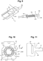
- FIG. 9 we can see a schematic representation of a cell which is a thin object suitable for characterization by the bench according to the invention. It comprises a positive electrode Ep, a negative electrode En, a separator S and the packaging EB surrounding the electrodes separated by the separator.
- the nominal thickness section is the part of the cell having the nominal thickness. It has a surface area equal to that of the element of the cell having the smallest surface area, generally this is the surface area of the positive electrode so as to guarantee proper electrochemical operation.
- the stimulus is electrical charging and/or discharging.
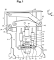
- the characterization bench comprises a frame 2 forming a base for the bench, a mobile assembly 4 mounted movable in translation in the vertical direction Z, and means 5 for applying a force in the vertical direction Z.
- the directions X and Y are directions orthogonal to the Z axis.
- the mobile assembly also includes a force sensor 18 to measure the force applied by the means 5.
- the means 5 for applying a force in the vertical direction Z are mounted on two uprights secured to the frame 2.
- the uprights 6 make it possible to ensure an acceptable orientation of the force applied in the desired direction, i.e. the Z direction, and make it possible to reduce the parasitic forces and moments on the mobile assembly and therefore on the cell to be tested.
- the frame and the uprights are made by assembling two flanges cut from a thick plate part.
- Feet 7 are provided to maintain the frame 2 and the uprights 6 in a vertical position.
- the bench includes a stress application zone 8 configured to receive the thin object, for example a battery cell C, and apply compression to it.
- the thin object for example a battery cell C
- the thin object will be referred to as “cell”.
- the stress application zone includes a lower compression set El and an upper compression set ES.
- the lower compression assembly El rests on the frame and is fixed along the vertical direction and in the XY plane.
- the lower compression assembly El comprises a compression face FC which is located in the center of the assembly and a measurement zone ZM surrounding the compression face FC.
- the displacement sensor(s) described below are in contact with the measurement area.
- the upper compression assembly ES is carried by the mobile assembly so as to be vertically in line with the lower compression assembly El and to be able to approach the lower compression assembly El.
- the upper compression assembly ES comprises a compression face FC which is located in the center of the assembly and a measurement zone ZM surrounding the compression face FC.
- the displacement sensor(s) described below are carried by the second measurement zone.
- the lower compression assembly El It comprises a first central part, called the first compression part which carries the first compression face FC1 and has a significant thickness.
- the first compression part 12 forms an anvil.
- the first compression part is made of hard material, for example a material having a Young's modulus greater than 160GPa, for example a steel avoiding crushing by pressure.
- the first measurement zone ZM1 is formed by a first frame 11 surrounding the first compression part 12.
- the first compression face FC1 projects from the upper face of the measurement zone ZM1.
- the area of the compression face FC1 is less than or equal to the area of the nominal thickness section of the cell.
- the section in compression has the two electrodes over its entire surface.
- the height of the projection is chosen so as not to compress the power tabs or any other element emerging laterally from the electrodes.
- a spacer 13 is placed between the frame 2 and the first compression part 12 making it possible to modify the position of the compression face FC1 along the axis Z.
- the contact between the frame 2 and the spacer 13 is a point or quasi-point support limiting the transmission of the deformation of the frame to the compression part.
- the first frame 11 includes a window 15 housing the compression part 12.
- the first frame 11 preferably has a thickness lower than the compression part.
- the lower compression assembly comprises, between the first measurement zone ZM1 and the first compression part 12, connection means ensuring great rigidity in the direction of movement Z and a certain flexibility in the plane XY in order to absorb the expansion of the compression part 12 in the XY plane and limit the risks of deformation of the measurement zone.
- the first compression part 12 has a generally square shape and the window of the first frame 11 also has a generally square shape identical to the shape of the first compression part 12.
- connection means ensure that the first compression part 12 and the first frame 11 have the same position along the direction Z
- the connection between the frame 11 and the compression part 12 is located at an altitude Z as close as possible from that of the surface in contact with the cell.
- the first compression part 12 comprises four arms 17 each extending from an outer edge of the first compression part 12 towards an inner edge of the first frame 11.
- two or three arms can be provided between the compression part and the frame.
- parts 11 and 12 can be machined in one piece and form a single part.
- the interior edges of the first frame 11 each carry a housing 19 receiving the free end 17.1 of an arm 17.
- the free end 17.1 of each arm 17 and each housing 19 have a through hole.
- the frame is fixed on the arms by means of screws, the arms being pierced with tapped holes, ensuring the rigid connection between the compression part 12 and the first frame 11.
- the exterior part of the compression zone 12 is connected to the frame 11 by a flexible zone capable of absorbing an expansion in X and Y of the compression zone without transmitting it to the measurement zone.
- the flexible connection between the compression part 12 and the frame is obtained by means of a light 23 formed in the first frame 11.
- the light 23 is through and extends orthogonally to the arm 17.
- Each light 23 is located between a housing 19 and the outer edge of the first frame 11.
- the lights 23 are of elongated shape and have advantageously a length greater than the width of a housing 19.
- the flexibility in the XY plane between the compression part 12 and the frame 11 makes it possible to guarantee the precision of displacement measurement.
- the compression part 12 undergoes a compressive stress in Z and due to the Poisson's ratio of the material of the compression part 12, it expands in the X and Y directions.
- the X-shaped expansion of the compression part reaches 600 nm.
- the deformable zones on the frame 11 absorb the expansion of the compression part, and prevent the frame from deforming into “chips” in a manner that is difficult to control. Such a deformation would induce a very significant measurement error, for example of several micrometers, in the measurement of the relative displacements in Z of the compression parts.
- a space 29 is provided between the outer edge of the compression part 12 and the frame 11 absorbing the expansion of the compression part 12 in these zones and avoiding contact with the frame.
- four spaces 29 are formed, a space being located between each vertex of the compression part and a vertex of the frame.
- the spaces are formed by L-shaped windows.
- the window 23 and the spaces 29 define staggered through recesses made in the measurement zone around the compression zone.
- the spaces 29 define two symmetrical recesses on either side of the arm 17.
- the spaces are empty.
- it can be filled in whole or in part with a sufficiently flexible material, such as an elastomer, which does not transmit the expansion of the compression part to the frame.
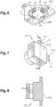
- the upper compression assembly ES has a shape and structure close to those of the lower pressure assembly El.
- the second compression part 12' comprises a second central part 12', called the second compression part, carrying the second compression face FC2 and having a significant thickness.
- the second compression part 12' forms an anvil.
- the second compression part 12' is also made of hard material, for example a material having a Young's modulus greater than 160GPa, for example a steel avoiding crushing by pressure.
- the upper compression assembly ES also comprises a second frame 11' surrounding the second compression part 12' and forming the second measurement zone.
- the second frame 11' includes a window 15' housing the second compression part 12'.
- the second frame 11' preferably has a thickness lower than the second compression part 12'.
- the upper compression assembly also includes connection means ensuring great rigidity in the direction of movement Z and a certain flexibility in the XY plane in order to absorb the expansion of the compression part in the XY plane and limit the risks of deformation of the measurement area.
- the second compression part 12' has the same shape as the first compression part 12 of the lower compression assembly El. It therefore has a generally square shape, and the window 15' of the second frame 11' has also a generally square shape identical to the shape of the second compression part 12'.
- the second compression part 12' and the second frame 11' are rigidly connected to each other at least along the Z direction so as to have the same position along the Z direction, and in the XY plane .
- the first compression part 12' comprises four arms 17' each extending from an outer edge of the second compression part 12' towards an inner edge of the second frame 11'.
- two or three arms can be provided between the compression part and the frame.
- the interior edges of the second frame 11' each carry a housing 19' receiving the free end 17.1' of an arm.
- the free end 17.1' of each arm 17' and each housing 19' have a tapped hole.
- the arms are secured to the housings, ensuring the rigid connection between the compression part 12' and the first frame 11' in the Z direction.
- the flexibility in the XY plane between the second compression part 12' and the second frame 11 is also obtained by means of through slots 23' extending orthogonally to the arms and located between the housings 19' and the holes 25.1 in the second frame 11' receiving the housings 25 of the displacement sensors.
- the slots 23' are elongated and advantageously have a length greater than the width of a housing 19'.
- the parts 11' and 12' can be machined in one piece and form a single part.
- a space is provided between the outer edge of the compression part 12' and the frame 11' absorbing the expansion of the compression part 12 in these areas and avoiding contact with the frame.
- the space is empty.
- it can be filled in whole or in part with a sufficiently flexible material, such as an elastomer, which does not transmit the expansion of the compression part to the frame.
- each window 23' and the spaces between the second compression part 12' and the frame form staggered through recesses.
- the second frame 11' also includes housings 25, three in the example shown, receiving the displacement sensors.
- the housings 25 are formed by tubes mounted in through holes 25.1 extending in the direction Z and the displacement sensors 16 are mounted in the tubes so that they are in contact with the first frame 11 and can measure the relative displacement of the first 11 and second 11' frames which correspond to the relative displacement of the first 12 and second 12 compression parts.
- displacement sensors with measurement reproducibility specifications of no more than 150 nm and a travel of 2 mm.
- the displacement sensor(s) 16 is or are one or more passive electrical linear displacement sensors or LVDT (Linear Variable Differential Transformer in English terminology). Alternatively, it may be one or more capacitive sensors. Several displacement sensors are advantageously used, which makes it possible to detect flatness defects during compression, i.e. for example an skewing of the mobile assembly.
- connection means between the frame 11, 11' and the compression part 12, 12' described above ensure stable, reproducible measurements.
- the means ensuring both great rigidity along Z and flexibility in the XY plane can be produced by three or four point contacts associated with a spring pinning the frame 11, 11' onto the compression part 12, 12' respectively.
- handling compression sets can be more complex.
- the second lower compression part 12' comprises a compression face FC2 projecting from the upper face of the second frame, in particular from the measurement zone ZM2 ( figures 7 and 8 ).
- the surface of the second compression face FC2 is equal to that of the first compression face FC1.
- the height of the projection is chosen so as not to compress the power tabs or any other element emerging laterally from the electrodes.
- one or the other of the compression faces FC1 and FC2 protrude relative to their respective frame and one or the other of the compression faces has a surface less than or equal to or equal to the surface of the nominal thickness section of the cell.
- the second compression part comprises a foot advantageously provided with two intersecting bores 27 extending in the plane XY, which allow distribution of the force exerted by the application means 5 on the compression face FC2 and to obtain even more uniform pressure and deformation on the FC2 compression face.
- the displacement sensors are part of the upper compression assembly ES and move with the second frame.
- the displacement sensors can be fixed on the first frame and sense the position of the second frame.
- one or two displacement sensors can or can be implemented.
- the part of the second frame not receiving a displacement sensor is of small width in the XY plane which gives this part the flexibility necessary to absorb the expansion of the part 12.
- the first and second frames comprise means for aligning one with respect to the other in the direction Z.
- the alignment means comprise centering rods 24 which cooperate with through holes 26 formed in the first frame and in the second frame. The installation of the rods in the holes 26 ensures the correct alignment of the lower and upper compression assemblies.
- the first and second compression faces have a certain flatness to ensure the homogeneous application of stresses within the cell, for example the faces of the anvils are ground, advantageously having a flatness difference of less than 1 ⁇ m.
- a lapping of the compression faces can be carried out, once the frames fixed on the compression parts, in order to guarantee a perfect correspondence of the compression faces facing each other with no play.
- the force application means 5 are carried by the uprights 6. They comprise an electric gear motor 34, a winding drum 35 in direct connection with the output shaft of the gear motor 34, a set of pulleys 38 carried by a first end of a first lever 40 which is articulated by a second end to one of the uprights 6 around a horizontal axis, a cable (not shown) wound on the two sets of pulleys 36, 38 forming a multiple hoist which amplifies the traction of the cable by a factor of 6, a second lever 42 articulated in rotation on the other upright 6 around a horizontal axis and connected to the first lever 40 by a cam 43.
- the force application means 5 are capable of applying a force of 10 kN on 10 cm 2 , ie 10 MPa.
- the force sensor 18 is arranged between the second compression part 12' and a compression rod 44 which bears against the lever 42 and transmits the force to the second compression part.
- a support 45 of the force sensor comprises a base against which the sensor 18 rests and a threaded tube whose passage opens into the base and makes it possible to receive the threaded rod of compression 44.
- the compression rod 44 and support 45 assembly is advantageously adjustable in length. In the retracted position, it can be installed in the housings provided in room 12'. Once in place, the rod is unscrewed in order to tighten the entire mobile assembly.
- the force is transmitted from the means 5 to the force application zone by two point or quasi-point contacts.
- the compression rod 44 is in point contact by its upper end with the lever 42.
- the upper end of the compression rod 44 has a conical shape which is received for example in a hole, for example of 1mm radius holding the upper end of the rod in position in the XY plane.
- the hole is drilled in the flat bottom of a circular housing with a diameter greater than the compression rod making it possible to block the latter in the event of sliding of the rod in the XY plane.
- the head of the screw 44 is spherical and is housed in a spherical bearing machined in the lever 42.
- the bearing can advantageously be made of low friction material, such as a polymer or self-adhesive bronze. lubricated for example).
- the force sensor comprises for example a spherical support head which is for example placed on the flat bottom of a circular housing machined in the upper part of the second compression part 12' in order to provide punctual support.
- the compression rod or the threaded tube is provided with calibrated stress gauges forming a force sensor and the two ends of the assembly carry either conical heads or spherical heads resting on a plane or on a spherical housing.
- Activation of the gear motor 34 raises or lowers the first lever which, via the cam, raises or lowers the second lever with a lower amplitude, between 10 and 20 times for example, modifying the force applied.
- the force application means 5 can make it possible to amplify the force by a factor of 100 between the traction force on the cable and the force applied to the anvils.
- the flexibility of the system as a whole, in particular the elasticity of the cable, the levers 40 and 42, the rods 44 and 45 and the uprights 6, allows a motor fitted with a reduction gear allowing 6000 steps/revolution to be able to regulate the force applied to within 1N when the bench is empty or the rigidity of the object tested is infinite.
- the gear motor can be controlled in real time depending on time and measured parameters, such as the state of charge of the cell, variations thickness measured by the displacement sensors. It is thus possible, for example, to keep the compression force constant in all circumstances, for example whatever the variation in thickness of the sample, or to vary the compression force with a law depending on the thickness of the sample. , or even vary the force over time to measure the “deformation as a function of pressure” characteristic of the sample.
- the means 5 have the advantage of storing low energy relative to the spring, the risks of ejection of the mobile assembly are therefore reduced.
- the centering rods 24 can be chosen thin since they only have a centering role.
- the compression rod 44 and support 45 assembly has a variable length, for this it can comprise two parts linked to each other by screwing, which allows its easy removal and frees up a large height between the means 5 and the mobile assembly, allowing access to the lower compression assembly El and to the displacement sensors.
- the force sensor is placed between the lever 42 and the compression rod.
- the point contact type connection is then made between the sensor and the lever and between the sensor and the compression rod. The system ensures almost punctual support of the compression rod on the lever in order to cancel out the swiveling forces.
- springs are provided to hold the levers in the high position allowing the compression rod and therefore the lower compression plate to be easily removed without the levers falling.
- the force sensor 18 is aligned with the Z axis along which the force is applied.
- the force sensor 18 measures the force applied to the cell. It should be noted that the weight of the mobile assembly (support plate, upper compression plate, displacement sensor(s) and possibly homogenization plate which will be described below) must be added to the force measured by the sensor. 18 to calculate the force applied to the sample.
- the force sensor 18 can be a sensor using an elastically deformable part and comprising deformation gauges, preferably sensors with four gauges organized in a “full bridge” and calibrated in temperature in order to guarantee a precise measurement and without drift over time, which therefore does not require periodic calibration.
- deformation gauges preferably sensors with four gauges organized in a “full bridge” and calibrated in temperature in order to guarantee a precise measurement and without drift over time, which therefore does not require periodic calibration.
- a D-Mesure ® force sensor model K450H-10kN, can be used.
- the second compression part 12' has a significant thickness and width, for example 30 mm by 30 mm, which ensures the flatness of the compression surface by homogenizing the stresses.
- a homogenization plate can be interposed between the upper compression assembly ES and the force sensor. It is preferably made of hard material, preferably having a Young's modulus greater than 160 GPa, for example of steel and has a thickness of at least 20 mm. The use of such a homogenization plate makes it possible to reduce the thickness of the second compression part while maintaining good homogeneity of deformation and pressure.
- the homogenization plate very advantageously comprises on its face in contact with the second compression part, a ring projecting from the surface forming an annular support against the second compression part.
- the bench is such that the points P1, P2 and P3 represented on the figure 1 are aligned with the Z axis, along which the compressive force is applied.
- P1 (not visible) is the center of gravity of the compression face FC2 of the upper compression assembly ES
- P2 is the point contact type connection point between the force sensor 18 and the rear face of the second part of compression 12'
- P3 is the upper longitudinal end of the compression rod opposite that of the side of the force sensor 18.
- the Z axis along which it is desired to apply the compression force to the cell passes through the points P1 and P2.
- the placement of the cell between the compression parts 12, 12' is such that it ensures that the section of nominal thickness is centered on the point P1.
- the positive electrode having a surface area smaller than that of the electrode negative
- the zone of application of the pressure is at most equal to the section of the object to be characterized having a substantially constant thickness, i.e. in the case of a cell it is the section of surface equal to that of the positive electrode.
- the characterization bench is particularly suitable for measuring the swelling/deflation of cells under load.
- the bench advantageously includes means for electrically connecting the cell to a generator/load depending on the measurement made.
- the characterization bench can be placed in a temperature-regulated enclosure, in which the bench would be protected from air flows and sources of thermal radiation. It is then possible to achieve a reproducibility of displacement measurements better than +/-50 nm with the bench according to the invention.
- the means for applying a force comprise a helical spring held in compression, the spring being coaxial with the axis Z.
- the means for applying the force make it possible to modify the intensity of the force applied.
- the spring 7 is supported by its longitudinal ends between two crosspieces perpendicular to the direction Z and fixed to the uprights and whose relative distance in the vertical direction is adjustable, making it possible to modify the compression of the spring and therefore to the effort applied to the cell.
- the crosspieces may each include a seat respectively housing the upper longitudinal end and the lower longitudinal end of the spring and fixing the alignment of its axis with the Z axis along which the force is to be applied.
- means can be provided for adjusting the alignment of the axis of the spring with the axis Z.
- the seat1 of the upper crosspiece can have several positions in a direction perpendicular to the axis Z to adjust the alignment of the spring to the Z axis.
- the means for applying the vertical force comprise a hydraulic or pneumatic cylinder.
- the means for applying the vertical force comprise a mechanical screw jack.
- both the upper compression assembly and the lower compression assembly comprise connection means ensuring flexibility in the XY plane between the compression part and the frame.
- only the upper compression assembly comprises such means and a lower compression assembly comprising a massive anvil exhibiting little or no expansion at the level of stresses considered.
- the implementation of the upper compression assembly ES as described in relation to the figures 6 to 8 has the advantage of offering a very light mobile crew.
- the cell is positioned for example on the first compression part 12 of the lower compression assembly El, so as to align the section of nominal thickness with the first compression face FC1.
- the corners of the electrode with a smaller surface area are identified, for example, by marking with a felt-tip pen the corners of the negative electrode of the cell with arrows F pointing towards each corner, starting from the outside.
- the lower compression assembly El comprises four L-shaped windows 29, the two branches of each L forming an interior angle oriented towards the compression part 12.
- the lower compression assembly is arranged above the cell, the compression zone facing the face of the cell carrying the arrows, and is positioned so as to align the end of each arrow F with an interior angle d an L-shaped window 29.
- An adhesive is advantageously used on the compression part 12 to fix the cell thereon.
- the cell can be positioned precisely and fixed on the compression part of the upper compression assembly and then be positioned on the mobile assembly facing the upper compression assembly.
- the mobile assembly is blocked in a high position to allow the installation of the lower compression assembly El.
- the lower compression assembly El is then positioned on the frame.
- the mobile assembly is released from its upper position and the second compression part 12' of the upper compression assembly ES compresses the cell.
- the rods 24 are removed after minimal force is applied to hold the moving parts in place.
- the applied force is measured by the force sensor 18 taking into account the weight of the mobile assembly.
- the displacement sensors measure the displacement between the lower compression assembly El and the upper compression assembly ES, more particularly between the first frame 11 and the second frame 11' which is the image of the inflation or deflation of the cell under a given constraint.
- the compression parts 12 and 12' expand in the X and Y direction under the effect of the pressure and the Poisson's ratio of the material which constitutes the compression parts 12 and 12'. Due to the flexibility in the X and Y direction of the contact between the frames 11 and the compression parts 12, the deformation of the compression parts has no or little effect on the measurement zones, even at the level of the connections by the arms 17, 17', the deformation that they could apply to the frames 11, 11' is absorbed by the lights 23, 23'. Thus a parasitic deformation of the measurement zones which would result from the compressive stress at the center of the compression sets due to the Poisson's ratio is avoided. The zones supporting the sensors and the zones where the displacement is measured do not undergo parasitic displacement in the Z direction. The precision of the displacement measurement is then increased.
- the characterization bench is particularly suited to the study of battery cells, in particular the negative electrodes of Lithium-ion cells comprising silicon.
- the bench makes it possible to apply uniform pressure on a surface of a single pair of electrodes on a surface of a sample of battery electrodes, for example a surface of 10cm 2 .
- a surface of a sample of battery electrodes for example a surface of 10cm 2 .
- the bench allows pressures of up to 10MPa to be applied, making it possible to study the entire range of pressures encountered in the cells up to stresses damaging to the cell, which also makes it possible to acquire useful data for studies of safety on the behavior of cells subjected to accidental stresses.
- the bench can make it possible to achieve a precision of +/-50nm in the direction of the thickness of the electrode which is the direction of application of the force, and to measure variations in electrode thickness to within 1%.
- common thickness variations being 5 to 10 ⁇ m, for graphite-silicon materials in common thicknesses.
- the motorized characterization bench of the figure 1 allows you to simulate the behavior of the electrode in a cell or pack packaging having arbitrary mechanical characteristics. In this case the applied force is controlled by the thickness measured via a pre-programmed function.
- the compression faces are configured to apply a compressive force to the section of nominal thickness of the cell, i.e. its section of greatest thickness, since this is the part of the cell that we wish to characterize . It will be understood that the part to be characterized of an object is not necessarily that of greatest thickness, it could be of smaller thickness.
- the surface of the compression face(s) is chosen less than or equal to the part of the object that we wish to characterize.
- This bench can for example be used to characterize the crushing under stress of porous materials in thin layers, for example used in proton exchange membrane fuel cells or PEMFC (Proton Exchange Membrane Fuel Cell in English terminology). -Saxon).
- the bench makes it possible to measure the mechanical characteristics of the different elements of the cell, in particular the Young's modulus. To do this, different levels of force are applied to the elements to be tested, for example to the complete cell. or on the separate elements of the cell, and we measure the displacement generated under the effect of this force.
- the displacement/pressure curve constitutes a law of behavior of the measured object.
- the measurement is dynamic: for example for the cell separator, impregnated with electrolyte, the movement is not instantaneous. It stabilizes after several tens of minutes to several hours after a change in applied force.
- the shape of the compression parts is adapted to the object that we wish to characterize. In the example described above we wanted to characterize a square-shaped battery cell.
- the compression parts are chosen square in shape. If the object characterized is of a polygonal shape other than square or disc-shaped, the compression parts are chosen to have a polygonal shape other than square or circular respectively.
Landscapes
- Engineering & Computer Science (AREA)
- Physics & Mathematics (AREA)
- General Physics & Mathematics (AREA)
- Manufacturing & Machinery (AREA)
- Chemical & Material Sciences (AREA)
- Chemical Kinetics & Catalysis (AREA)
- Electrochemistry (AREA)
- General Chemical & Material Sciences (AREA)
- Aviation & Aerospace Engineering (AREA)
- Investigating Strength Of Materials By Application Of Mechanical Stress (AREA)
- Battery Mounting, Suspending (AREA)
- Secondary Cells (AREA)
Claims (15)
- Bank zur mechanischen Charakterisierung eines dünnen Objekts durch Anwendung einer Druckkraft entlang einer gegebenen Druckachse (Z), beinhaltend:- ein Gestell (2),- eine untere Druckbaugruppe (EI), die auf dem Gestell (2) ruht, und eine erste Druckfläche (FC1) beinhaltet,- ein bewegliches Organ (4), das entlang der Druckachse (Z) relativ zum Gestell (2) beweglich ist, und eine obere Druckbaugruppe (ES) trägt, die eine zweite Druckfläche (FC2) gegenüber der ersten Druckfläche (FC1) beinhaltet,- Pfosten (6), die am Gestell (2) befestigt sind,- Mittel zur Anwendung (5) einer Kraft entlang der Achse des Drucks (Z) auf das Objekt, die ausgewählt sind, um zwischen der ersten und zweiten Druckfläche angeordnet zu sein, wobei die Kraft von bestimmter Intensität und orthogonal zur ersten und zweiten Druckfläche ist, wobei die Mittel zur Anwendung (5) am Pfosten (6) befestigt sind,- mindestens einen Kraftsensor (18), der zwischen dem beweglichen Organ (4) und den Mitteln zur Anwendung einer Kraft (5) eingesetzt ist,- mindestens einen Verschiebungssensor (16), der arrangiert ist, um die Verschiebung zwischen der ersten Druckfläche (FC1) und der zweiten Druckfläche (FC2) in der Richtung der Druckachse (Z) zu messen,wobei die obere Druckbaugruppe (ES) einen zweiten Druckbereich (12') beinhaltet, der die zweite Druckfläche (FC2) trägt, und einen zweiten Rahmen (11'), der den zweiten Druckbereich (12') umgibt, wobei der zweite Druckbereich (12') und der zweite Rahmen (11') mindestens in Richtung der Druckachse (Z) starr miteinander verbunden sind und eine Verbindung in den Richtungen (X, Y) aufweisen, die orthogonal zur Verschiebungsrichtung sind, und eine reduzierte Steifigkeit aufweisen, so dass eine Verformung des zweiten Druckbereichs (12') in der Ebene, die orthogonal zur Druckrichtung (Z) ist, den zweiten Rahmen (11') nicht oder nur geringfügig verformt, und wobei der mindestens eine Verschiebungssensor (16) die Verschiebung zwischen der oberen Druckbaugruppe (ES) und der unteren Druckbaugruppe (EI) misst.
- Bank zur Charakterisierung nach Anspruch 1, wobei die untere Druckbaugruppe (EI) einen ersten Druckbereich (12) beinhaltet, der die erste Druckfläche (FC1) trägt und einen ersten Rahmen (11), der den ersten Druckbereich (12) umgibt, wobei der erste Druckbereich (12) und der erste Rahmen (11) mindestens in Richtung der Druckachse (Z) starr miteinander verbunden sind, und eine Verbindung in den Richtungen (X, Y) aufweisen, die orthogonal zur Verschiebungsrichtung sind, und eine reduzierte Steifigkeit aufweisen, so dass eine Verformung des ersten Druckbereichs (12) in der Ebene, die orthogonal zur Druckrichtung (Z) ist, den ersten Rahmen (11) nicht oder nur geringfügig verformt.
- Bank zur Charakterisierung nach Anspruch 2, wobei der erste Druckbereich (12) an den ersten Rahmen (11) durch mindestens zwei erste Arme (17) angeschlossen ist, die sich vom ersten Druckbereich (12) erstrecken, wobei ein freies Ende (17.1) jedes ersten Arms (17) fest mit einer Kante des ersten Rahmens (11) verbunden ist, und wobei eine Lichtquelle (23) im ersten Rahmen (11), die die Dicke des ersten Rahmens (11) im Wesentlichen orthogonal zum Arm durchquert, gegenüber jedem freien Ende (17.1) eines Arms (17) angeordnet ist.
- Bank zur Charakterisierung nach einem der Ansprüche 1 bis 3, wobei der zweite Druckbereich (12') an den zweiten Rahmen (11') durch mindestens zwei zweite Arme (17') angeschlossen ist, die sich vom zweiten Druckbereich (12') erstrecken, wobei ein freies Ende (17.1') jedes zweiten Arms (17') fest mit einer Kante des zweiten Rahmens (11') verbunden ist, und wobei eine Lichtquelle (23') im zweiten Rahmen (11'), die die Dicke des zweiten Rahmens (11') im Wesentlichen orthogonal zum Arm durchquert, gegenüber jedem freien Ende (17.1') eines Arms (17) angeordnet ist.
- Bank zur Charakterisierung nach einem der Ansprüche 1 bis 4, wobei mindestens die eine der ersten (FC1) und zweiten (FC2) Druckflächen eine hervorstehende Druckzone beinhalten, dessen Oberfläche kleiner oder gleich eines Bereichs von Interesse des zu charakterisierenden Objekts ist, wobei optional die Druckzone eine Oberfläche hat, die der Oberfläche des Bereichs von Interesse des Objekts entspricht.
- Bank zur Charakterisierung nach Anspruch 3 und 4, wobei der mindestens eine Verschiebungssensor (16) vom ersten (11) oder zweiten (11') Rahmen getragen wird und mit dem zweiten (11') oder ersten (11) Rahmen in Kontakt steht, um die Verschiebung zwischen dem ersten Rahmen (11) und dem zweiten Rahmen (11') zu messen.
- Bank zur Charakterisierung nach einem der Ansprüche 1 bis 6, drei Verschiebungssensoren (16) beinhaltend, die um die Druckachse (Z) verteilt sind, und Mittel, die konfiguriert sind, um ihre Messungen zu vergleichen und einen Fehler in der Ebenheit zu erkennen.
- Bank zur Charakterisierung nach einem der Ansprüche 1 bis 7, wobei der zweite Druckbereich einen Fuß nach der zweiten Druckfläche (FC2) in der Richtung der Anwendung der Druckkraft beinhaltet, wobei der Fuß zwei sich schneidende Bohrungen beinhaltet, die in einer Ebene orthogonal zur Richtung (Z) der Anwendung der Kraft angeordnet sind.
- Bank zur Charakterisierung nach einem der Ansprüche 1 bis 8, wobei die Druckkraft von den Mitteln zur Anwendung einer Kraft (5) an die erste (FC1) und zweite (FC2) Druckfläche durch mindestens eine Verbindung des Punktkontakttyps übertragen wird, wobei optional der mindestens eine Kraftsensor (18) über eine Verbindung des Punktkontakttyps an die Mittel zur Anwendung einer Kraft angeschlossen ist.
- Bank zur Charakterisierung nach einem der Ansprüche 1 bis 9, wobei die Mittel zur Anwendung einer Kraft (5) Mittel zum Verändern der Intensität der angewendeten Kraft beinhalten.
- Bank zur Charakterisierung nach einem der Ansprüche 1 bis 10, wobei die Mittel zur Anwendung einer Kraft einen Getriebeschrittmotor beinhalten, mindestens eine erste Seilrolle in direktem Eingriff mit der Abtriebswelle des Getriebemotors, eine zweite Seilrolle, ein Seil zwischen der ersten und der zweiten Seilrolle, mindestens einen ersten Hebel, der die zweite Seilrolle trägt, und einen zweiten Hebel, der am ersten Hebel angelenkt ist, und wobei eine Druckstange zwischen dem zweiten Hebel und der zweiten Druckfläche vorgesehen ist, wobei optional der mindestens eine Kraftsensor zwischen dem zweiten Hebel und der Druckstange arrangiert ist.
- Bank zur Charakterisierung nach Anspruch 11, wobei die Kraftübertragung zwischen den Mitteln zur Anwendung einer Kraft und der zweiten Druckfläche über zwei Verbindungen vom Punktkontakttyp erfolgt, wobei optional die Druckstange in Punktkontakt mit dem zweiten Hebel und dem mindestens einen Kraftsensor steht.
- Verfahren zur Charakterisierung eines dünnen Objekts unter Verwendung einer Bank zur Charakterisierung nach einem der vorhergehenden Ansprüche, beinhaltend:- Positionieren des Objekts auf der ersten Druckfläche, um den Bereich von Interesse mit der Druckzone auszurichten,- Anwendung der zweiten Druckfläche auf das Objekt,- die Messung der Verschiebung zwischen den zwei Druckflächen in Abhängigkeit von einem angewendeten Druckaufwand.
- Verfahren zur Charakterisierung nach Anspruch 13, wobei ein Stimulus angewendet wird, um eine Veränderung des Volumens des Objekts während der Messung zu bewirken.
- Verfahren zur Charakterisierung nach Anspruch 13 oder 14, wobei das dünne Objekt eine elektrochemische Batteriezelle ist, deren Bereich von Interesse der Bereich ist, der den Stapel beinhaltet, der durch die positive Elektrode, den Separator, die negative Elektrode und eine Verpackung um den Stapel gebildet wird, wobei das Verfahren, während den Messungen, einen Schritt zur Anwendung eines elektrischen Lade- und/oder Entladungszyklus beinhaltet.
Applications Claiming Priority (2)
| Application Number | Priority Date | Filing Date | Title |
|---|---|---|---|
| FR1915166A FR3105416B1 (fr) | 2019-12-20 | 2019-12-20 | Banc de caracterisation mecanique d’objets minces a fiabilite augmentee |
| PCT/FR2020/052453 WO2021123609A1 (fr) | 2019-12-20 | 2020-12-15 | Banc de caracterisation mecanique d'objets minces a fiabilite augmentee |
Publications (2)
| Publication Number | Publication Date |
|---|---|
| EP4078710A1 EP4078710A1 (de) | 2022-10-26 |
| EP4078710B1 true EP4078710B1 (de) | 2023-12-13 |
Family
ID=70295290
Family Applications (1)
| Application Number | Title | Priority Date | Filing Date |
|---|---|---|---|
| EP20845583.2A Active EP4078710B1 (de) | 2019-12-20 | 2020-12-15 | Bank zur mechanischen charakterisierung von dünnen objekten mit erhöhter zuverlässigkeit |
Country Status (4)
| Country | Link |
|---|---|
| US (1) | US12135260B2 (de) |
| EP (1) | EP4078710B1 (de) |
| FR (1) | FR3105416B1 (de) |
| WO (1) | WO2021123609A1 (de) |
Families Citing this family (2)
| Publication number | Priority date | Publication date | Assignee | Title |
|---|---|---|---|---|
| GB2619557B (en) * | 2022-06-10 | 2025-07-16 | Virtual Vehicle Res Gmbh | Device for measuring thickness changes of battery cells |
| TWI860690B (zh) * | 2023-04-21 | 2024-11-01 | 國立中山大學 | 電芯噴發力量量測平台 |
Family Cites Families (10)
| Publication number | Priority date | Publication date | Assignee | Title |
|---|---|---|---|---|
| US6539809B1 (en) * | 1999-04-18 | 2003-04-01 | Testing Machines, Inc. | Test apparatus for measuring stresses and strains |
| KR101058388B1 (ko) * | 2007-02-08 | 2011-08-22 | 주식회사 엘지화학 | 이차전지 검사 장치 |
| DE102011100605A1 (de) * | 2011-05-05 | 2012-11-08 | Li-Tec Battery Gmbh | Messverfahren für eine elektrochemische Energiespeichereinrichtung und Messvorrichtung |
| US8541855B2 (en) | 2011-05-10 | 2013-09-24 | Magic Technologies, Inc. | Co/Ni multilayers with improved out-of-plane anisotropy for magnetic device applications |
| WO2016085271A1 (ko) * | 2014-11-26 | 2016-06-02 | 주식회사 엘지화학 | 이차전지 셀의 두께 측정장치 및 방법 |
| KR101783923B1 (ko) * | 2014-11-26 | 2017-10-10 | 주식회사 엘지화학 | 이차전지 셀의 두께 측정장치 및 방법 |
| KR102070684B1 (ko) * | 2017-01-24 | 2020-01-29 | 주식회사 엘지화학 | 이차 전지 평가 장치 |
| KR102095358B1 (ko) * | 2017-02-24 | 2020-03-31 | 주식회사 엘지화학 | 전지 재료의 두께 측정기 |
| FR3105397B1 (fr) * | 2019-12-20 | 2021-12-10 | Commissariat Energie Atomique | Banc de caracterisation mecanique d’objets minces |
| US20230296676A1 (en) * | 2022-03-15 | 2023-09-21 | Wildcat Discovery Technologies, Inc. | System for assessment of battery cell dimensional variation |
-
2019
- 2019-12-20 FR FR1915166A patent/FR3105416B1/fr active Active
-
2020
- 2020-12-15 EP EP20845583.2A patent/EP4078710B1/de active Active
- 2020-12-15 WO PCT/FR2020/052453 patent/WO2021123609A1/fr not_active Ceased
- 2020-12-15 US US17/787,289 patent/US12135260B2/en active Active
Also Published As
| Publication number | Publication date |
|---|---|
| FR3105416B1 (fr) | 2021-12-17 |
| FR3105416A1 (fr) | 2021-06-25 |
| US12135260B2 (en) | 2024-11-05 |
| WO2021123609A1 (fr) | 2021-06-24 |
| US20230021162A1 (en) | 2023-01-19 |
| EP4078710A1 (de) | 2022-10-26 |
Similar Documents
| Publication | Publication Date | Title |
|---|---|---|
| EP4078710B1 (de) | Bank zur mechanischen charakterisierung von dünnen objekten mit erhöhter zuverlässigkeit | |
| WO2021123602A1 (fr) | Banc de caracterisation mecanique d'objets minces | |
| EP2711696B1 (de) | Wärmeflusssensor mit Schwingelement und Gas-Sensor mit wenigstens einem solchen Wärmeflusssensor | |
| CA2898258C (fr) | Dispositif de laminage, procede de laminage, film d'electrolyte ainsi obtenu et ensemble de stockage d'energie forme a partir d'au moins un film ainsi lamine. | |
| FR2998044A1 (fr) | Systeme de guidage pour panneaux solaires | |
| EP1960307A1 (de) | Mikroelektromechanisches system mit einem verformbaren teil und einem belastungssensor | |
| FR3082902A1 (fr) | Roulement a billes, unite de mesure de couple de friction sous charge equipee d’un tel roulement, et banc d’essais pour dispositif tournant equipe d’une telle unite de mesure | |
| WO2014049062A1 (fr) | Capteur de pression a base de nanojauges couplees a un resonateur | |
| FR3078405A1 (fr) | Unite de mesure de couple de friction sous charge, et banc d’essais pour dispositif tournant equipe d’une telle unite de mesure | |
| WO2012101385A1 (fr) | Miroir deformable a capteurs capacitifs | |
| WO2003081170A2 (fr) | Dispositif de mesure extensometrique | |
| EP4016199A1 (de) | Vorrichtung und verfahren zum testen einer mechanischen eigenschaft einer uhrenwelle | |
| EP0968450A1 (de) | Mikrometrische positionierungsvorrichtung einer halterung eines optischen elements mit sechs freiheitsgraden | |
| FR3093175A1 (fr) | Systeme de mesure d’une deformation de surface en flexion d’un materiau | |
| KR20220040931A (ko) | 로드 셀을 포함하는 전지 셀 가압 지그, 및 이를 이용한 전지 셀 가압 방법과 스웰링 측정 방법 | |
| EP1055097A1 (de) | Lotüberwachungsverfahren für zylindrische objekte wie kernbrennstofftabletten | |
| WO2023031557A1 (fr) | Banc d'essai en cisaillement | |
| EP1062670B1 (de) | Verfahren zum zusammenstellen einer optischen einheit mit koaxialen schalen, insbesondere für ein röntgenteleskop | |
| EP4661154A1 (de) | Vorrichtung zur messung von abmessungsänderungen an elektrochemischen zellen von batterien | |
| FR2616901A1 (fr) | Extensometre multi-axial, en particulier extensometre tri-axial | |
| EP4391142A2 (de) | Vorrichtung und verfahren zur erkennung einer verformung einer verpackung einer batteriezelle | |
| FR3112608A1 (fr) | Banc d’essai et son procédé de mise en œuvre | |
| FR2735231A1 (fr) | Appareil de mesure de force a capteur optique permettant la limitation de defauts d'excentration, notamment pour un pese-personne, et procede de realisation d'un tel appareil | |
| WO2025088007A1 (fr) | Rhéomètre haute fréquence à double actionneurs | |
| FR2663116A1 (fr) | Appareil de mesure de parametres physiques de surface d'un solide. |
Legal Events
| Date | Code | Title | Description |
|---|---|---|---|
| STAA | Information on the status of an ep patent application or granted ep patent |
Free format text: STATUS: UNKNOWN |
|
| STAA | Information on the status of an ep patent application or granted ep patent |
Free format text: STATUS: THE INTERNATIONAL PUBLICATION HAS BEEN MADE |
|
| PUAI | Public reference made under article 153(3) epc to a published international application that has entered the european phase |
Free format text: ORIGINAL CODE: 0009012 |
|
| STAA | Information on the status of an ep patent application or granted ep patent |
Free format text: STATUS: REQUEST FOR EXAMINATION WAS MADE |
|
| 17P | Request for examination filed |
Effective date: 20220617 |
|
| AK | Designated contracting states |
Kind code of ref document: A1 Designated state(s): AL AT BE BG CH CY CZ DE DK EE ES FI FR GB GR HR HU IE IS IT LI LT LU LV MC MK MT NL NO PL PT RO RS SE SI SK SM TR |
|
| DAV | Request for validation of the european patent (deleted) | ||
| DAX | Request for extension of the european patent (deleted) | ||
| GRAP | Despatch of communication of intention to grant a patent |
Free format text: ORIGINAL CODE: EPIDOSNIGR1 |
|
| STAA | Information on the status of an ep patent application or granted ep patent |
Free format text: STATUS: GRANT OF PATENT IS INTENDED |
|
| INTG | Intention to grant announced |
Effective date: 20230731 |
|
| GRAS | Grant fee paid |
Free format text: ORIGINAL CODE: EPIDOSNIGR3 |
|
| GRAA | (expected) grant |
Free format text: ORIGINAL CODE: 0009210 |
|
| STAA | Information on the status of an ep patent application or granted ep patent |
Free format text: STATUS: THE PATENT HAS BEEN GRANTED |
|
| AK | Designated contracting states |
Kind code of ref document: B1 Designated state(s): AL AT BE BG CH CY CZ DE DK EE ES FI FR GB GR HR HU IE IS IT LI LT LU LV MC MK MT NL NO PL PT RO RS SE SI SK SM TR |
|
| REG | Reference to a national code |
Ref country code: GB Ref legal event code: FG4D Free format text: NOT ENGLISH |
|
| REG | Reference to a national code |
Ref country code: CH Ref legal event code: EP |
|
| REG | Reference to a national code |
Ref country code: DE Ref legal event code: R096 Ref document number: 602020022857 Country of ref document: DE |
|
| REG | Reference to a national code |
Ref country code: IE Ref legal event code: FG4D Free format text: LANGUAGE OF EP DOCUMENT: FRENCH |
|
| PG25 | Lapsed in a contracting state [announced via postgrant information from national office to epo] |
Ref country code: GR Free format text: LAPSE BECAUSE OF FAILURE TO SUBMIT A TRANSLATION OF THE DESCRIPTION OR TO PAY THE FEE WITHIN THE PRESCRIBED TIME-LIMIT Effective date: 20240314 |
|
| REG | Reference to a national code |
Ref country code: LT Ref legal event code: MG9D |
|
| PG25 | Lapsed in a contracting state [announced via postgrant information from national office to epo] |
Ref country code: LT Free format text: LAPSE BECAUSE OF FAILURE TO SUBMIT A TRANSLATION OF THE DESCRIPTION OR TO PAY THE FEE WITHIN THE PRESCRIBED TIME-LIMIT Effective date: 20231213 |
|
| REG | Reference to a national code |
Ref country code: NL Ref legal event code: MP Effective date: 20231213 |
|
| PG25 | Lapsed in a contracting state [announced via postgrant information from national office to epo] |
Ref country code: ES Free format text: LAPSE BECAUSE OF FAILURE TO SUBMIT A TRANSLATION OF THE DESCRIPTION OR TO PAY THE FEE WITHIN THE PRESCRIBED TIME-LIMIT Effective date: 20231213 |
|
| PG25 | Lapsed in a contracting state [announced via postgrant information from national office to epo] |
Ref country code: LT Free format text: LAPSE BECAUSE OF FAILURE TO SUBMIT A TRANSLATION OF THE DESCRIPTION OR TO PAY THE FEE WITHIN THE PRESCRIBED TIME-LIMIT Effective date: 20231213 Ref country code: GR Free format text: LAPSE BECAUSE OF FAILURE TO SUBMIT A TRANSLATION OF THE DESCRIPTION OR TO PAY THE FEE WITHIN THE PRESCRIBED TIME-LIMIT Effective date: 20240314 Ref country code: ES Free format text: LAPSE BECAUSE OF FAILURE TO SUBMIT A TRANSLATION OF THE DESCRIPTION OR TO PAY THE FEE WITHIN THE PRESCRIBED TIME-LIMIT Effective date: 20231213 Ref country code: BG Free format text: LAPSE BECAUSE OF FAILURE TO SUBMIT A TRANSLATION OF THE DESCRIPTION OR TO PAY THE FEE WITHIN THE PRESCRIBED TIME-LIMIT Effective date: 20240313 |
|
| REG | Reference to a national code |
Ref country code: AT Ref legal event code: MK05 Ref document number: 1641246 Country of ref document: AT Kind code of ref document: T Effective date: 20231213 |
|
| PG25 | Lapsed in a contracting state [announced via postgrant information from national office to epo] |
Ref country code: NL Free format text: LAPSE BECAUSE OF FAILURE TO SUBMIT A TRANSLATION OF THE DESCRIPTION OR TO PAY THE FEE WITHIN THE PRESCRIBED TIME-LIMIT Effective date: 20231213 |
|
| PG25 | Lapsed in a contracting state [announced via postgrant information from national office to epo] |
Ref country code: SE Free format text: LAPSE BECAUSE OF FAILURE TO SUBMIT A TRANSLATION OF THE DESCRIPTION OR TO PAY THE FEE WITHIN THE PRESCRIBED TIME-LIMIT Effective date: 20231213 Ref country code: RS Free format text: LAPSE BECAUSE OF FAILURE TO SUBMIT A TRANSLATION OF THE DESCRIPTION OR TO PAY THE FEE WITHIN THE PRESCRIBED TIME-LIMIT Effective date: 20231213 Ref country code: NO Free format text: LAPSE BECAUSE OF FAILURE TO SUBMIT A TRANSLATION OF THE DESCRIPTION OR TO PAY THE FEE WITHIN THE PRESCRIBED TIME-LIMIT Effective date: 20240313 Ref country code: NL Free format text: LAPSE BECAUSE OF FAILURE TO SUBMIT A TRANSLATION OF THE DESCRIPTION OR TO PAY THE FEE WITHIN THE PRESCRIBED TIME-LIMIT Effective date: 20231213 Ref country code: LV Free format text: LAPSE BECAUSE OF FAILURE TO SUBMIT A TRANSLATION OF THE DESCRIPTION OR TO PAY THE FEE WITHIN THE PRESCRIBED TIME-LIMIT Effective date: 20231213 Ref country code: HR Free format text: LAPSE BECAUSE OF FAILURE TO SUBMIT A TRANSLATION OF THE DESCRIPTION OR TO PAY THE FEE WITHIN THE PRESCRIBED TIME-LIMIT Effective date: 20231213 |
|
| PG25 | Lapsed in a contracting state [announced via postgrant information from national office to epo] |
Ref country code: IS Free format text: LAPSE BECAUSE OF FAILURE TO SUBMIT A TRANSLATION OF THE DESCRIPTION OR TO PAY THE FEE WITHIN THE PRESCRIBED TIME-LIMIT Effective date: 20240413 |
|
| PG25 | Lapsed in a contracting state [announced via postgrant information from national office to epo] |
Ref country code: CZ Free format text: LAPSE BECAUSE OF FAILURE TO SUBMIT A TRANSLATION OF THE DESCRIPTION OR TO PAY THE FEE WITHIN THE PRESCRIBED TIME-LIMIT Effective date: 20231213 Ref country code: AT Free format text: LAPSE BECAUSE OF FAILURE TO SUBMIT A TRANSLATION OF THE DESCRIPTION OR TO PAY THE FEE WITHIN THE PRESCRIBED TIME-LIMIT Effective date: 20231213 |
|
| PG25 | Lapsed in a contracting state [announced via postgrant information from national office to epo] |
Ref country code: SK Free format text: LAPSE BECAUSE OF FAILURE TO SUBMIT A TRANSLATION OF THE DESCRIPTION OR TO PAY THE FEE WITHIN THE PRESCRIBED TIME-LIMIT Effective date: 20231213 |
|
| PG25 | Lapsed in a contracting state [announced via postgrant information from national office to epo] |
Ref country code: SM Free format text: LAPSE BECAUSE OF FAILURE TO SUBMIT A TRANSLATION OF THE DESCRIPTION OR TO PAY THE FEE WITHIN THE PRESCRIBED TIME-LIMIT Effective date: 20231213 Ref country code: SK Free format text: LAPSE BECAUSE OF FAILURE TO SUBMIT A TRANSLATION OF THE DESCRIPTION OR TO PAY THE FEE WITHIN THE PRESCRIBED TIME-LIMIT Effective date: 20231213 Ref country code: RO Free format text: LAPSE BECAUSE OF FAILURE TO SUBMIT A TRANSLATION OF THE DESCRIPTION OR TO PAY THE FEE WITHIN THE PRESCRIBED TIME-LIMIT Effective date: 20231213 Ref country code: IT Free format text: LAPSE BECAUSE OF FAILURE TO SUBMIT A TRANSLATION OF THE DESCRIPTION OR TO PAY THE FEE WITHIN THE PRESCRIBED TIME-LIMIT Effective date: 20231213 Ref country code: IS Free format text: LAPSE BECAUSE OF FAILURE TO SUBMIT A TRANSLATION OF THE DESCRIPTION OR TO PAY THE FEE WITHIN THE PRESCRIBED TIME-LIMIT Effective date: 20240413 Ref country code: EE Free format text: LAPSE BECAUSE OF FAILURE TO SUBMIT A TRANSLATION OF THE DESCRIPTION OR TO PAY THE FEE WITHIN THE PRESCRIBED TIME-LIMIT Effective date: 20231213 Ref country code: CZ Free format text: LAPSE BECAUSE OF FAILURE TO SUBMIT A TRANSLATION OF THE DESCRIPTION OR TO PAY THE FEE WITHIN THE PRESCRIBED TIME-LIMIT Effective date: 20231213 Ref country code: AT Free format text: LAPSE BECAUSE OF FAILURE TO SUBMIT A TRANSLATION OF THE DESCRIPTION OR TO PAY THE FEE WITHIN THE PRESCRIBED TIME-LIMIT Effective date: 20231213 |
|
| REG | Reference to a national code |
Ref country code: CH Ref legal event code: PL |
|
| PG25 | Lapsed in a contracting state [announced via postgrant information from national office to epo] |
Ref country code: PL Free format text: LAPSE BECAUSE OF FAILURE TO SUBMIT A TRANSLATION OF THE DESCRIPTION OR TO PAY THE FEE WITHIN THE PRESCRIBED TIME-LIMIT Effective date: 20231213 Ref country code: PT Free format text: LAPSE BECAUSE OF FAILURE TO SUBMIT A TRANSLATION OF THE DESCRIPTION OR TO PAY THE FEE WITHIN THE PRESCRIBED TIME-LIMIT Effective date: 20240415 |
|
| PG25 | Lapsed in a contracting state [announced via postgrant information from national office to epo] |
Ref country code: LU Free format text: LAPSE BECAUSE OF NON-PAYMENT OF DUE FEES Effective date: 20231215 |
|
| REG | Reference to a national code |
Ref country code: BE Ref legal event code: MM Effective date: 20231231 |
|
| PG25 | Lapsed in a contracting state [announced via postgrant information from national office to epo] |
Ref country code: PT Free format text: LAPSE BECAUSE OF FAILURE TO SUBMIT A TRANSLATION OF THE DESCRIPTION OR TO PAY THE FEE WITHIN THE PRESCRIBED TIME-LIMIT Effective date: 20240415 Ref country code: PL Free format text: LAPSE BECAUSE OF FAILURE TO SUBMIT A TRANSLATION OF THE DESCRIPTION OR TO PAY THE FEE WITHIN THE PRESCRIBED TIME-LIMIT Effective date: 20231213 Ref country code: LU Free format text: LAPSE BECAUSE OF NON-PAYMENT OF DUE FEES Effective date: 20231215 |
|
| REG | Reference to a national code |
Ref country code: DE Ref legal event code: R097 Ref document number: 602020022857 Country of ref document: DE |
|
| PG25 | Lapsed in a contracting state [announced via postgrant information from national office to epo] |
Ref country code: MC Free format text: LAPSE BECAUSE OF FAILURE TO SUBMIT A TRANSLATION OF THE DESCRIPTION OR TO PAY THE FEE WITHIN THE PRESCRIBED TIME-LIMIT Effective date: 20231213 |
|
| REG | Reference to a national code |
Ref country code: IE Ref legal event code: MM4A |
|
| PG25 | Lapsed in a contracting state [announced via postgrant information from national office to epo] |
Ref country code: IE Free format text: LAPSE BECAUSE OF NON-PAYMENT OF DUE FEES Effective date: 20231215 |
|
| PG25 | Lapsed in a contracting state [announced via postgrant information from national office to epo] |
Ref country code: DK Free format text: LAPSE BECAUSE OF FAILURE TO SUBMIT A TRANSLATION OF THE DESCRIPTION OR TO PAY THE FEE WITHIN THE PRESCRIBED TIME-LIMIT Effective date: 20231213 |
|
| PG25 | Lapsed in a contracting state [announced via postgrant information from national office to epo] |
Ref country code: BE Free format text: LAPSE BECAUSE OF NON-PAYMENT OF DUE FEES Effective date: 20231231 |
|
| PLBE | No opposition filed within time limit |
Free format text: ORIGINAL CODE: 0009261 |
|
| STAA | Information on the status of an ep patent application or granted ep patent |
Free format text: STATUS: NO OPPOSITION FILED WITHIN TIME LIMIT |
|
| PG25 | Lapsed in a contracting state [announced via postgrant information from national office to epo] |
Ref country code: CH Free format text: LAPSE BECAUSE OF NON-PAYMENT OF DUE FEES Effective date: 20231231 |
|
| PG25 | Lapsed in a contracting state [announced via postgrant information from national office to epo] |
Ref country code: SI Free format text: LAPSE BECAUSE OF FAILURE TO SUBMIT A TRANSLATION OF THE DESCRIPTION OR TO PAY THE FEE WITHIN THE PRESCRIBED TIME-LIMIT Effective date: 20231213 |
|
| RAP4 | Party data changed (patent owner data changed or rights of a patent transferred) |
Owner name: COMMISSARIAT A L'ENERGIE ATOMIQUE ET AUX ENERGIESALTERNATIVES |
|
| PG25 | Lapsed in a contracting state [announced via postgrant information from national office to epo] |
Ref country code: SI Free format text: LAPSE BECAUSE OF FAILURE TO SUBMIT A TRANSLATION OF THE DESCRIPTION OR TO PAY THE FEE WITHIN THE PRESCRIBED TIME-LIMIT Effective date: 20231213 Ref country code: IE Free format text: LAPSE BECAUSE OF NON-PAYMENT OF DUE FEES Effective date: 20231215 Ref country code: DK Free format text: LAPSE BECAUSE OF FAILURE TO SUBMIT A TRANSLATION OF THE DESCRIPTION OR TO PAY THE FEE WITHIN THE PRESCRIBED TIME-LIMIT Effective date: 20231213 Ref country code: CH Free format text: LAPSE BECAUSE OF NON-PAYMENT OF DUE FEES Effective date: 20231231 Ref country code: BE Free format text: LAPSE BECAUSE OF NON-PAYMENT OF DUE FEES Effective date: 20231231 |
|
| 26N | No opposition filed |
Effective date: 20240916 |
|
| PG25 | Lapsed in a contracting state [announced via postgrant information from national office to epo] |
Ref country code: FI Free format text: LAPSE BECAUSE OF FAILURE TO SUBMIT A TRANSLATION OF THE DESCRIPTION OR TO PAY THE FEE WITHIN THE PRESCRIBED TIME-LIMIT Effective date: 20231213 |
|
| PG25 | Lapsed in a contracting state [announced via postgrant information from national office to epo] |
Ref country code: CY Free format text: LAPSE BECAUSE OF FAILURE TO SUBMIT A TRANSLATION OF THE DESCRIPTION OR TO PAY THE FEE WITHIN THE PRESCRIBED TIME-LIMIT; INVALID AB INITIO Effective date: 20201215 |
|
| PG25 | Lapsed in a contracting state [announced via postgrant information from national office to epo] |
Ref country code: HU Free format text: LAPSE BECAUSE OF FAILURE TO SUBMIT A TRANSLATION OF THE DESCRIPTION OR TO PAY THE FEE WITHIN THE PRESCRIBED TIME-LIMIT; INVALID AB INITIO Effective date: 20201215 |
|
| GBPC | Gb: european patent ceased through non-payment of renewal fee |
Effective date: 20241215 |
|
| PG25 | Lapsed in a contracting state [announced via postgrant information from national office to epo] |
Ref country code: GB Free format text: LAPSE BECAUSE OF NON-PAYMENT OF DUE FEES Effective date: 20241215 |
|
| PG25 | Lapsed in a contracting state [announced via postgrant information from national office to epo] |
Ref country code: TR Free format text: LAPSE BECAUSE OF FAILURE TO SUBMIT A TRANSLATION OF THE DESCRIPTION OR TO PAY THE FEE WITHIN THE PRESCRIBED TIME-LIMIT Effective date: 20231213 |
|
| PGFP | Annual fee paid to national office [announced via postgrant information from national office to epo] |
Ref country code: FR Payment date: 20251222 Year of fee payment: 6 |
|
| PGFP | Annual fee paid to national office [announced via postgrant information from national office to epo] |
Ref country code: DE Payment date: 20251222 Year of fee payment: 6 |