EP4078704B1 - Cooling of a fuel cell - Google Patents
Cooling of a fuel cell Download PDFInfo
- Publication number
- EP4078704B1 EP4078704B1 EP21708153.8A EP21708153A EP4078704B1 EP 4078704 B1 EP4078704 B1 EP 4078704B1 EP 21708153 A EP21708153 A EP 21708153A EP 4078704 B1 EP4078704 B1 EP 4078704B1
- Authority
- EP
- European Patent Office
- Prior art keywords
- flow
- plate
- plate element
- elevations
- bipolar plate
- Prior art date
- Legal status (The legal status is an assumption and is not a legal conclusion. Google has not performed a legal analysis and makes no representation as to the accuracy of the status listed.)
- Active
Links
- 239000000446 fuel Substances 0.000 title description 8
- 238000001816 cooling Methods 0.000 title description 6
- 239000002826 coolant Substances 0.000 claims description 12
- 230000001419 dependent effect Effects 0.000 claims description 4
- 238000000926 separation method Methods 0.000 claims 1
- 239000000498 cooling water Substances 0.000 description 26
- 239000007789 gas Substances 0.000 description 6
- 239000012528 membrane Substances 0.000 description 6
- 238000009826 distribution Methods 0.000 description 5
- 238000005520 cutting process Methods 0.000 description 4
- 239000003054 catalyst Substances 0.000 description 3
- 239000003792 electrolyte Substances 0.000 description 3
- XLYOFNOQVPJJNP-UHFFFAOYSA-N water Substances O XLYOFNOQVPJJNP-UHFFFAOYSA-N 0.000 description 3
- QVGXLLKOCUKJST-UHFFFAOYSA-N atomic oxygen Chemical compound [O] QVGXLLKOCUKJST-UHFFFAOYSA-N 0.000 description 2
- 238000006073 displacement reaction Methods 0.000 description 2
- 239000000463 material Substances 0.000 description 2
- 239000001301 oxygen Substances 0.000 description 2
- 229910052760 oxygen Inorganic materials 0.000 description 2
- 239000000126 substance Substances 0.000 description 2
- UFHFLCQGNIYNRP-UHFFFAOYSA-N Hydrogen Chemical compound [H][H] UFHFLCQGNIYNRP-UHFFFAOYSA-N 0.000 description 1
- 238000010521 absorption reaction Methods 0.000 description 1
- 230000015572 biosynthetic process Effects 0.000 description 1
- 238000006243 chemical reaction Methods 0.000 description 1
- 239000004020 conductor Substances 0.000 description 1
- 238000009792 diffusion process Methods 0.000 description 1
- 238000005868 electrolysis reaction Methods 0.000 description 1
- 238000004049 embossing Methods 0.000 description 1
- 239000012530 fluid Substances 0.000 description 1
- 239000001257 hydrogen Substances 0.000 description 1
- 229910052739 hydrogen Inorganic materials 0.000 description 1
- 238000004519 manufacturing process Methods 0.000 description 1
- 238000000034 method Methods 0.000 description 1
- 238000005457 optimization Methods 0.000 description 1
- 230000000737 periodic effect Effects 0.000 description 1
- 239000005518 polymer electrolyte Substances 0.000 description 1
- 238000001179 sorption measurement Methods 0.000 description 1
- 239000002918 waste heat Substances 0.000 description 1
Images


Classifications
-
- H—ELECTRICITY
- H01—ELECTRIC ELEMENTS
- H01M—PROCESSES OR MEANS, e.g. BATTERIES, FOR THE DIRECT CONVERSION OF CHEMICAL ENERGY INTO ELECTRICAL ENERGY
- H01M8/00—Fuel cells; Manufacture thereof
- H01M8/02—Details
- H01M8/0202—Collectors; Separators, e.g. bipolar separators; Interconnectors
- H01M8/0258—Collectors; Separators, e.g. bipolar separators; Interconnectors characterised by the configuration of channels, e.g. by the flow field of the reactant or coolant
-
- H—ELECTRICITY
- H01—ELECTRIC ELEMENTS
- H01M—PROCESSES OR MEANS, e.g. BATTERIES, FOR THE DIRECT CONVERSION OF CHEMICAL ENERGY INTO ELECTRICAL ENERGY
- H01M8/00—Fuel cells; Manufacture thereof
- H01M8/02—Details
- H01M8/0202—Collectors; Separators, e.g. bipolar separators; Interconnectors
- H01M8/0267—Collectors; Separators, e.g. bipolar separators; Interconnectors having heating or cooling means, e.g. heaters or coolant flow channels
-
- H—ELECTRICITY
- H01—ELECTRIC ELEMENTS
- H01M—PROCESSES OR MEANS, e.g. BATTERIES, FOR THE DIRECT CONVERSION OF CHEMICAL ENERGY INTO ELECTRICAL ENERGY
- H01M8/00—Fuel cells; Manufacture thereof
- H01M8/02—Details
- H01M8/0297—Arrangements for joining electrodes, reservoir layers, heat exchange units or bipolar separators to each other
-
- H—ELECTRICITY
- H01—ELECTRIC ELEMENTS
- H01M—PROCESSES OR MEANS, e.g. BATTERIES, FOR THE DIRECT CONVERSION OF CHEMICAL ENERGY INTO ELECTRICAL ENERGY
- H01M8/00—Fuel cells; Manufacture thereof
- H01M8/04—Auxiliary arrangements, e.g. for control of pressure or for circulation of fluids
- H01M8/04007—Auxiliary arrangements, e.g. for control of pressure or for circulation of fluids related to heat exchange
- H01M8/04029—Heat exchange using liquids
-
- H—ELECTRICITY
- H01—ELECTRIC ELEMENTS
- H01M—PROCESSES OR MEANS, e.g. BATTERIES, FOR THE DIRECT CONVERSION OF CHEMICAL ENERGY INTO ELECTRICAL ENERGY
- H01M8/00—Fuel cells; Manufacture thereof
- H01M8/10—Fuel cells with solid electrolytes
- H01M2008/1095—Fuel cells with polymeric electrolytes
-
- H—ELECTRICITY
- H01—ELECTRIC ELEMENTS
- H01M—PROCESSES OR MEANS, e.g. BATTERIES, FOR THE DIRECT CONVERSION OF CHEMICAL ENERGY INTO ELECTRICAL ENERGY
- H01M8/00—Fuel cells; Manufacture thereof
- H01M8/02—Details
- H01M8/0202—Collectors; Separators, e.g. bipolar separators; Interconnectors
- H01M8/0258—Collectors; Separators, e.g. bipolar separators; Interconnectors characterised by the configuration of channels, e.g. by the flow field of the reactant or coolant
- H01M8/026—Collectors; Separators, e.g. bipolar separators; Interconnectors characterised by the configuration of channels, e.g. by the flow field of the reactant or coolant characterised by grooves, e.g. their pitch or depth
-
- Y—GENERAL TAGGING OF NEW TECHNOLOGICAL DEVELOPMENTS; GENERAL TAGGING OF CROSS-SECTIONAL TECHNOLOGIES SPANNING OVER SEVERAL SECTIONS OF THE IPC; TECHNICAL SUBJECTS COVERED BY FORMER USPC CROSS-REFERENCE ART COLLECTIONS [XRACs] AND DIGESTS
- Y02—TECHNOLOGIES OR APPLICATIONS FOR MITIGATION OR ADAPTATION AGAINST CLIMATE CHANGE
- Y02E—REDUCTION OF GREENHOUSE GAS [GHG] EMISSIONS, RELATED TO ENERGY GENERATION, TRANSMISSION OR DISTRIBUTION
- Y02E60/00—Enabling technologies; Technologies with a potential or indirect contribution to GHG emissions mitigation
- Y02E60/30—Hydrogen technology
- Y02E60/50—Fuel cells
Definitions
- the invention relates to a bipolar plate for cooling an electrochemical cell, and to an electrochemical cell, in particular a fuel cell, with such a bipolar plate.
- Electrochemical cells are well known. In a galvanic electrochemical cell, chemical energy is converted into electrical energy, in reversal of electrolysis.
- a known device for such a galvanic cell is the fuel cell, in which the chemical energy carrier is not stored in the cell, but is continuously made available from outside, which means that continuous operation is in principle possible.
- a well-known type of fuel cell is the low-temperature fuel cell based on polymer electrolyte membrane (PEM) technology, whose main areas of application are primarily in the mobile sector without using waste heat, for example in submarines.
- PEM polymer electrolyte membrane
- the essential element of a PEM single cell is a membrane electrode unit. This consists of two electrodes (an anode and a cathode) and an electrolyte membrane located between the two electrodes. Between the electrodes and the electrolyte membrane there is a catalyst layer in which the important physical and electrochemical processes, such as adsorption of hydrogen and oxygen on the catalyst, release and absorption of electrons and the formation of water on the cathode side by combination of protons diffused through the membrane and ( reduced) oxygen.
- the important physical and electrochemical processes such as adsorption of hydrogen and oxygen on the catalyst, release and absorption of electrons and the formation of water on the cathode side by combination of protons diffused through the membrane and ( reduced) oxygen.
- the electrodes are located on the side facing away from the electrolyte membrane or catalyst layer Side via a gas diffusion layer in contact with a so-called bipolar plate.
- This component has the task of separating the individual fuel cells (on the media side), ensuring current flow in the cell stack and removing the reaction heat.
- the bipolar plates are made of an electrically conductive material, which must have a low contact resistance to the electrodes.
- these bipolar plates consist of two plate elements, which are often provided with a milled gas channel structure, and cooling water flows through them during operation.
- bipolar plate An example of a bipolar plate can be found in the DE 10 2014 206 336 A1 .
- the bipolar plate disclosed there comprises two plates arranged together, each of which has a periodic structure with recesses in cross section, with recesses in the recesses of both plates being arranged facing away from one another to form a coolant flow area.
- the recesses are formed exclusively in a distributor structure of the bipolar plate that is arranged in the main flow direction before and/or after a flow field and partially overlap, so that a coolant flow area that allows longitudinal and transverse flow is provided.
- bipolar plate is from the US 2007/0015019 A1 and from the WO 2004/107486 A1 known.
- the separator or bipolar plate comprises two profiled plate elements that touch each other on contact surfaces, between which a fluid or flow space for the coolant is formed.
- the plate elements have several embossments arranged on the surface of the plate elements in the manner of round elevations facing away from one another with recesses facing one another.
- the embossings of both plate elements are offset relative to one another, so that the centers of the studs are one Plate element lies above a triangle center point of the other plate element, so that flow paths for the cooling water between the plates are opened, in which the water can flow from the nub of the lower plate element into the nub of the upper plate element.
- the object of the invention is to provide a bipolar plate for an electrochemical cell which enables improved cooling and which is at the same time as simple and inexpensive to produce as possible.
- a further object of the invention is to provide an electrochemical cell with such a bipolar plate.
- the invention is based on the knowledge that in the areas of temperature peaks the cooling water flow is lower than in better cooled areas and that this non-uniformity is caused by the flow resistance being isotropic evenly over the surface. This means that the edge and corner areas in particular receive less flow than the central area of the cooling field.
- the invention solves the problem directed at a bipolar plate by providing that in such a bipolar plate for an electrochemical cell, comprising a flow space arranged between a first plate element and a second plate element with a flow inlet and a flow outlet for a coolant flowing through the flow space, wherein each plate element has a contact level for contacting the other plate element and between the flow inlet and the flow outlet a plurality of elevations protruding from the contact plane and facing away from the other plate element, which have openings towards the contact plane, and wherein first flow channels are formed through the openings of the elevations in that the elevations of both plate elements are offset from one another , wherein each elevation at least partially overlaps at least one elevation of the other plate element, a direction-dependent flow resistance is set in the first flow channels of the bipolar plate by arranging the elevations on the plate elements in the corners of regular triangles and the plate elements are arranged offset from one another, so that in a projection onto the contact plane, an elevation of the first plate element is arranged off-center
- the cooling water can be e.g. B. preferably direct in the width, i.e. transversely to the direct line between flow inlet and flow outlet, in particular into the corners of the bipolar plate, and only then direct into the length of the cell.
- the streamline pattern is also expanded and the cooling water can be directed into the corner areas better than in the case of a homogeneous flow resistance distribution.
- the exact setting of the flow field and thus the temperature field can be influenced by the amount of displacement.
- elevations have frusto-conical profiles with regard to the production of the plate elements but also with regard to the flow behavior of the cooling medium in the first flow channels.
- the elevations on the plate elements are arranged in the corners of regular triangles and the plate elements are arranged offset from one another, so that in a projection onto the contact plane, an elevation of the first plate element is arranged off-center within a triangle of elevations of the second plate element.
- the streamline pattern is also expanded and the cooling water can be directed into the corner areas better than in the case of a homogeneous flow resistance distribution.
- the exact setting of the flow field and thus the temperature field can be influenced by the amount of displacement.
- a main axis of a plate element which is defined by two adjacent elevations of a plate element, is oriented perpendicular to the connecting line, with one elevation of the first plate element being displaced from a centered position relative to the next three elevations of the second plate element parallel to the connecting line is so that its distance from the next elevation of the second plate element in a direction parallel to the connecting line is greater than from the other two next elevations of the second plate element.
- the cooling medium flow is preferably set perpendicular to the direct connecting line between the flow inlet and flow outlet.
- At least two elevations of a plate element are combined to form a second flow channel.
- the passage areas between the two plate elements become larger and the flow resistance becomes smaller.
- the second flow channels are arranged at least in edge regions of the bipolar plate without a flow inlet or flow outlet. It is particularly advantageous if the second flow channels form an annular channel running around the edges of the bipolar plate, i.e. in the edge regions.
- a separating web is formed between two adjacent second flow channels of a plate element, the distance of which from the contact plane is different from zero. If necessary, a height of the separator can be zero, i.e. there is no longer a separator 16 between two adjacent second flow channels. By appropriately choosing the web height, the flow resistance and thus the volume flow can be adjusted to the desired extent.
- an orientation of a second flow channel of the first plate element is different from the orientation of a second flow channel of the second plate element.
- the task directed at an electrochemical cell is solved by an electrochemical cell comprising at least one bipolar plate according to the invention.
- the offset of the elevations only influences the cooling water space; the gas space of the cells, which is located outside the flow space for the cooling water, is not influenced.
- a bipolar plate 1 for a fuel cell is shown in a schematic top view.
- a flow space 4 for coolant K for example cooling water, is formed within the bipolar plate 1. Cooling water is introduced into the flow space 4 through a flow inlet 5 and led out through a flow outlet 6 arranged on an opposite side. The flow inlet 5 and the flow outlet 6 lie on a diagonal line, not shown here.
- the flow space 4 is delimited on its two flat sides by two plate elements 2, 3 of which in Figure 1 only a first plate element 2 is visible.
- the plate elements 2, 3 are metallic.
- the surfaces of the plate elements 2, 3 also have a profiling, which is in Figure 1 is not shown.
- the structure and arrangement of the plate elements 2, 3 according to the prior art is in the Figures 2 , 3 and 4 shown.
- a large number of knob-shaped elevations 8 are embossed into the plate elements 2, 3.
- the elevations 8 of the first plate element 2 are drawn with a continuous line, while the elevations 8 of the second plate element 3 are marked with a dashed line.
- FIG 2 A main flow direction 17 is also shown, which is essentially represented by the connecting line 11 between the flow inlet 5 and the flow outlet 6.
- FIG 3 shows a somewhat more detailed top view of two plate elements 2, 3 positioned one above the other of a bipolar plate 1 according to the prior art.
- the basic hydraulic elements of the cooling water space of the bipolar plate 1 are shown.
- a possible path of the cooling water flow in the bipolar plate 1 is shown as an example with a cutting line 12.
- the side view of the section along section line 12 is in Figure 4 shown and best describes how the cooling water path results.
- the elevations 8 of one of the plate elements 2, 3 face away from the other plate element 2, 3.
- the surveys 8 according to FIG 2 , FIG 3 and FIG 4 all have a circular cross section and are the same size and symmetrically arranged.
- Each of the plate elements 2, 3 has a contact plane 7 with which it rests on the other plate element 2, 3 and from which the elevations 8 protrude outwards. The contact between the two plate elements 2, 3 takes place in the contact level 7.
- the elevations 8 or knobs embossed in the material of the plate elements 2, 3 have an opening 9 towards the contact plane 7.
- the elevations 8 are offset from one another.
- Such an arrangement results in contact areas 18 (see Figure 3 ), where the plate elements 2, 3 touch and therefore no cooling water can flow.
- areas 19 also form in which the elevations 8 partially overlap.
- cooling water can flow from one side of the contact plane 7 to the other, so that a large number of discrete first flow channels 10 for the cooling water K run through the elevations 8 in the flow space 4.
- Figure 3 shows a part of a first flow channel 10, the course of which also follows the cutting line 12.
- a first flow channel 10 is indicated by the curved arrows.
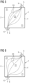
- Figure 5 shows the streamlines 20 of the cooling water in the bipolar plate 1 according to the prior art in a highly simplified schematic representation. Corner areas 21 receive a comparatively small amount of flow, while the central area 22 receives a comparatively strong amount of flow. This results in an uneven temperature distribution in the bipolar plate 1. Because of the low cooling water flow in the corner areas 21, higher temperatures arise there during operation than in the central area 22.
- Figure 6 shows the streamlines 20 of the cooling water in the bipolar plate 1 according to the invention.
- the corner areas 21 have a greater flow of cooling water through them, while the central area 22 has a correspondingly weaker flow. This can result in a homogeneous temperature distribution right down to the corner areas.
- FIGs 7 and 8 show, so to speak, a hydraulic basic element of the flow space 4 of a bipolar plate 1.
- Figure 7 shows the prior art, in which the center 14 of an elevation 8 of the first plate element 2 lies above a triangle center 15 of the second plate element 3 and in which there is no flow resistance for a cooling medium depends on the direction, which means that the cooling medium seeks the shortest path from the flow inlet 5 to the flow outlet 6 and this essentially extends along the connecting line 11 (see Figure 2 ).
- the corner areas 21 are flowed through less by the cooling medium than the middle area 22 (see Figure 5 ).
- This flow behavior changes when the plate elements 2, 3 are displaced relative to one another in such a way that the center 14 of an elevation 8 of the first plate element 2 is no longer above a triangle center 15 of the second plate element 3, but is shifted approximately in the direction of the flow inlet 5, which results in passage areas of different sizes for different directions in the flow space 4.
- Figure 8 is a main axis 24 of a plate element 2, 3, which is defined by two adjacent elevations 8 of a plate element 2, 3, oriented perpendicular to the connecting line 11, with an elevation 8 of the first plate element 2 from a centered position relative to the next three elevations 8 of the second plate element 3 is shifted parallel to the connecting line 11, so that its distance to the next elevation 8 of the second plate element 3 is greater in a direction parallel to the connecting line 11 than to the other two next elevations 8 of the second plate element 3.
- FIGS 9 and 10 show an exemplary embodiment of an edge region 23 of the plate elements 2, 3 that has been modified compared to the prior art
- Figure 9 schematically a horizontal section through a part of the first plate element 2, ie a section parallel to the plane of the first plate element 2.
- Figure 10 shows a corresponding section for the second plate element 3.
- Figure 9 also shows a vertical section through the first plate element 2 in the edge region 23.
- the section runs transversely to elevations 8, which are combined in the edge region 23 to form second flow channels 13.
- the second flow channels 13 are separated by a separating web 16.
- a height of the Separating web 16, i.e. the difference between the height of the elevations 8 and the distance of the separating web 16 from the contact plane 7, can be freely selected and thus also the flow resistance in the edge region 23.
- h With h becomes in Figure 9 denotes the distance of the separating web 16 from the contact level 7.
- the height of the elevations 8 is marked H.
- a comparatively small h means a comparatively large flow resistance in the edge region 23, at least between the second flow channels 13, a comparatively large h, ie the web is almost eliminated, therefore means a comparatively small resistance between the second channels 13 in the edge region 23.
- h corresponds the height H of the elevations 8 above the contact level 7.
- annular channel 25 running around the edge regions 23 can be formed.
- a ring channel 25 is in the Figure 11 indicated.
- the representation in the Figure 11 is very schematic and different from the Figure 6 just by this feature.
- the ring channel 25 does not necessarily have to, as in the Figure 11 shown, have a constant width along the entire flow path. Deviations are possible; it may be desirable for the flow resistance to be particularly low, particularly in the corners.
Landscapes
- Life Sciences & Earth Sciences (AREA)
- Engineering & Computer Science (AREA)
- Manufacturing & Machinery (AREA)
- Sustainable Development (AREA)
- Sustainable Energy (AREA)
- Chemical & Material Sciences (AREA)
- Chemical Kinetics & Catalysis (AREA)
- Electrochemistry (AREA)
- General Chemical & Material Sciences (AREA)
- Fuel Cell (AREA)
Description
Die Erfindung betrifft eine Bipolarplatte für die Kühlung einer elektrochemischen Zelle, sowie eine elektrochemische Zelle, insbesondere eine Brennstoffzelle, mit einer solchen Bipolarplatte.The invention relates to a bipolar plate for cooling an electrochemical cell, and to an electrochemical cell, in particular a fuel cell, with such a bipolar plate.
Elektrochemische Zellen sind allgemein bekannt. In einer galvanischen elektrochemischen Zelle wird, in Umkehrung einer Elektrolyse, chemische in elektrische Energie umgewandelt. Eine bekannte Vorrichtung einer solchen galvanischen Zelle ist die Brennstoffzelle, bei der der chemische Energieträger nicht in der Zelle gespeichert, sondern von außen kontinuierlich zur Verfügung gestellt wird, wodurch ein kontinuierlicher Betrieb prinzipiell möglich ist.Electrochemical cells are well known. In a galvanic electrochemical cell, chemical energy is converted into electrical energy, in reversal of electrolysis. A known device for such a galvanic cell is the fuel cell, in which the chemical energy carrier is not stored in the cell, but is continuously made available from outside, which means that continuous operation is in principle possible.
Eine bekannter Brennstoffzellentyp ist die Niedrigtemperatur-Brennstoffzelle auf Basis der Polymer-Elektrolyt-Membran-(PEM)-Technologie, deren Hauptanwendungsgebiete vor allem im mobilen Bereich ohne Abwärmenutzung sind, beispielsweise in U-Booten.A well-known type of fuel cell is the low-temperature fuel cell based on polymer electrolyte membrane (PEM) technology, whose main areas of application are primarily in the mobile sector without using waste heat, for example in submarines.
Wesentliches Element einer PEM-Einzelzelle ist eine Membranelektrodeneinheit. Diese besteht aus zwei Elektroden (einer Anode und einer Kathode) und einer sich zwischen den beiden Elektroden befindlichen Elektrolytmembran. Zwischen den Elektroden und der Elektrolytmembran befindet sich eine Katalysatorschicht, in der die wichtigen physikalischen und elektrochemischen Vorgänge, wie Adsorption von Wasserstoff und Sauerstoff am Katalysator, Abgabe und Aufnahme von Elektronen und die Bildung von Wasser kathodenseitig durch Kombination von durch die Membran diffundierten Protonen und (reduziertem) Sauerstoff erfolgen.The essential element of a PEM single cell is a membrane electrode unit. This consists of two electrodes (an anode and a cathode) and an electrolyte membrane located between the two electrodes. Between the electrodes and the electrolyte membrane there is a catalyst layer in which the important physical and electrochemical processes, such as adsorption of hydrogen and oxygen on the catalyst, release and absorption of electrons and the formation of water on the cathode side by combination of protons diffused through the membrane and ( reduced) oxygen.
In einem Brennstoffzellenstapel befinden sich die Elektroden an der der Elektrolytmembran bzw. Katalysatorschicht abgewandten Seite über eine Gasdiffusionsschicht in Kontakt mit jeweils einer sogenannten Bipolarplatte. Dieses Bauteil hat die Aufgabe, die einzelnen Brennstoffzellen (medienseitig) zu trennen, für Stromfluss im Zellstapel zu sorgen und die Reaktionswärme zu entfernen. Um einen effektiven Stromfluss zu gewährleisten, bestehen die Bipolarplatten aus einem elektrisch-leitenden Material, welches einen niedrigen Übergangswiderstand zu den Elektroden aufweisen muss.In a fuel cell stack, the electrodes are located on the side facing away from the electrolyte membrane or catalyst layer Side via a gas diffusion layer in contact with a so-called bipolar plate. This component has the task of separating the individual fuel cells (on the media side), ensuring current flow in the cell stack and removing the reaction heat. In order to ensure an effective current flow, the bipolar plates are made of an electrically conductive material, which must have a low contact resistance to the electrodes.
Typischerweise bestehen diese Bipolarplatten aus zwei Plattenelementen, die mit einer oft eingefrästen Gaskanalstruktur versehen sind, und werden im Betrieb von Kühlwasser durchströmt.Typically, these bipolar plates consist of two plate elements, which are often provided with a milled gas channel structure, and cooling water flows through them during operation.
Ein Beispiel für eine Bipolarplatte findet sich in der
Weitere Beispiele für eine Bipolarplatte sind aus der
Alle Erhebungen/Noppen oder alle Erhebungen/Noppen eines bestimmten Bereichs sind dabei gleich groß. Die Durchlassbereiche sind an allen Positionen gleich groß. Trotzdem ist das Temperaturfeld inhomogen und weist lokale Spitzen auf.All elevations/nubs or all elevations/nubs in a certain area are the same size. The passbands are the same size at all positions. Nevertheless, the temperature field is inhomogeneous and has local peaks.
Bereiche mit hohen Temperaturen beeinträchtigen dort die Haltbarkeit der Materialien, insbesondere, wenn die Temperaturen deutlich über dem mittleren Temperaturverlauf liegen.Areas with high temperatures affect the durability of the materials, especially if the temperatures are significantly above the average temperature range.
Aufgabe der Erfindung ist es, eine Bipolarplatte für eine elektrochemische Zelle bereitzustellen, die eine verbesserte Kühlung ermöglicht und die zugleich möglichst einfach und kostengünstig herzustellen ist. Eine weitere Aufgabe der Erfindung ist es, eine elektrochemische Zelle mit einer solchen Bipolarplatte bereitzustellen.The object of the invention is to provide a bipolar plate for an electrochemical cell which enables improved cooling and which is at the same time as simple and inexpensive to produce as possible. A further object of the invention is to provide an electrochemical cell with such a bipolar plate.
Die Erfindung geht von der Erkenntnis aus, dass in den Bereichen der Temperaturspitzen der Kühlwasserstrom geringer als in besser gekühlten Bereichen ist und dass diese Ungleichmä-ßigkeit dadurch verursacht wird, dass der Strömungswiderstand gleichmäßig über der Fläche isotrop ist. Dies führt dazu, dass besonders die Rand- und Eckbereiche weniger durchströmt werden als der Mittenbereich des Kühlfeldes.The invention is based on the knowledge that in the areas of temperature peaks the cooling water flow is lower than in better cooled areas and that this non-uniformity is caused by the flow resistance being isotropic evenly over the surface. This means that the edge and corner areas in particular receive less flow than the central area of the cooling field.
Die Erfindung löst die auf eine Bipolarplatte gerichtete Aufgabe, indem sie vorsieht, dass bei einer derartigen Bipolarplatte für eine elektrochemische Zelle, umfassend einen zwischen einem ersten Plattenelement und einem zweiten Plattenelement angeordneten Strömungsraum mit einem Strömungseinlass sowie einem Strömungsauslass für ein den Strömungsraum durchströmendes Kühlmittel, wobei jedes Plattenelement eine Kontaktebene zum Kontaktieren des jeweils anderen Plattenelements sowie zwischen dem Strömungseinlass und dem Strömungsauslass eine Vielzahl von aus der Kontaktebene herausragenden und dem jeweils anderen Plattenelement abgewandten Erhebungen aufweist, die zur Kontaktebene hin Öffnungen aufweisen, und wobei erste Strömungskanäle durch die Öffnungen der Erhebungen gebildet sind, indem die Erhebungen beider Plattenelemente zueinander versetzt sind, wobei jede Erhebung mindestens eine Erhebung des jeweils anderen Plattenelements zumindest teilweise überlappt, ein richtungsabhängiger Strömungswiderstand in den ersten Strömungskanälen der Bipolarplatte eingestellt ist, indem die Erhebungen auf den Plattenelementen in den Ecken regelmäßiger Dreiecke angeordnet sind und die Plattenelemente gegeneinander versetzt angeordnet sind, sodass in einer Projektion auf die Kontaktebene eine Erhebung des ersten Plattenelements innerhalb eines Dreiecks aus Erhebungen des zweiten Plattenelements außermittig angeordnet ist. Dadurch entstehen Durchlassbereiche, die nicht mehr alle gleich sind, sondern in bestimmten Bereichen größer, in anderen kleiner werden. Dadurch wird der Strömungswiderstand inhomogen bzw. richtungsabhängig. Es gibt Bereiche (Linien), in denen er kleiner ist und solche, in denen er größer ist als bei der zentrierten Anordnung. Durch diese Inhomogenität lässt sich das Kühlwasser z. B. bevorzugt in die Breite, also quer zur direkten Linie zwischen Strömungseinlass und Strömungsauslass, lenken, insbesondere in die Ecken der Bipolarplatte, und dann erst in die Länge der Zelle leiten. Das Stromlinienbild wird damit ebenfalls in die Breite gezogen und das Kühlwasser kann besser als im Fall einer homogenen Strömungswiderstandverteilung in die Eckbereiche geleitet werden. Die genaue Einstellung des Strömungsfeldes und damit des Temperaturfeldes kann durch das Maß der Verschiebung beeinflusst werden.The invention solves the problem directed at a bipolar plate by providing that in such a bipolar plate for an electrochemical cell, comprising a flow space arranged between a first plate element and a second plate element with a flow inlet and a flow outlet for a coolant flowing through the flow space, wherein each plate element has a contact level for contacting the other plate element and between the flow inlet and the flow outlet a plurality of elevations protruding from the contact plane and facing away from the other plate element, which have openings towards the contact plane, and wherein first flow channels are formed through the openings of the elevations in that the elevations of both plate elements are offset from one another , wherein each elevation at least partially overlaps at least one elevation of the other plate element, a direction-dependent flow resistance is set in the first flow channels of the bipolar plate by arranging the elevations on the plate elements in the corners of regular triangles and the plate elements are arranged offset from one another, so that in a projection onto the contact plane, an elevation of the first plate element is arranged off-center within a triangle of elevations of the second plate element. This creates pass areas that are no longer all the same, but become larger in certain areas and smaller in others. This makes the flow resistance inhomogeneous or direction-dependent. There are areas (lines) where it is smaller and those where it is larger than with the centered arrangement. Due to this inhomogeneity, the cooling water can be e.g. B. preferably direct in the width, i.e. transversely to the direct line between flow inlet and flow outlet, in particular into the corners of the bipolar plate, and only then direct into the length of the cell. The streamline pattern is also expanded and the cooling water can be directed into the corner areas better than in the case of a homogeneous flow resistance distribution. The exact setting of the flow field and thus the temperature field can be influenced by the amount of displacement.
Dabei ist es vorteilhaft, wenn der Strömungswiderstand in Richtung einer Verbindungslinie zwischen Strömungseinlass und Strömungsauslass größer ist als senkrecht dazu, sodass insbesondere die Randbereiche ohne Strömungseinlass oder Strömungsauslass von dieser Inhomogenität profitieren.It is advantageous if the flow resistance in the direction of a connecting line between the flow inlet and flow outlet is greater than perpendicular to it, so that in particular the edge areas without a flow inlet or flow outlet benefit from this inhomogeneity.
Es ist weiterhin vorteilhaft, wenn die Erhebungen im Hinblick auf die Herstellung der Plattenelemente aber auch im Hinblick auf ein Strömungsverhalten des Kühlmediums in den ersten Strömungskanälen kegelstumpfförmige Profile aufweisen.It is furthermore advantageous if the elevations have frusto-conical profiles with regard to the production of the plate elements but also with regard to the flow behavior of the cooling medium in the first flow channels.
In einer vorteilhaften Ausführungsform sind die Erhebungen auf den Plattenelementen in den Ecken regelmäßiger Dreiecke angeordnet und die Plattenelemente sind gegeneinander versetzt angeordnet, sodass in einer Projektion auf die Kontaktebene eine Erhebung des ersten Plattenelements innerhalb eines Dreiecks aus Erhebungen des zweiten Plattenelements außermittig angeordnet ist. Dadurch entstehen Durchlassbereiche, die nicht mehr alle gleich sind, sondern in bestimmten Bereichen größer, in anderen kleiner werden. Dadurch wird der Strömungswiderstand inhomogen bzw. richtungsabhängig. Es gibt Bereiche (Linien), in denen er kleiner ist und solche, in denen er größer ist als bei der zentrierten Anordnung. Durch diese Inhomogenität lässt sich das Kühlwasser z. B. bevorzugt in die Breite, also quer zur direkten Linie zwischen Strömungseinlass und Strömungsauslass, lenken, insbesondere in die Ecken der Bipolarplatte, und dann erst in die Länge der Zelle leiten. Das Stromlinienbild wird damit ebenfalls in die Breite gezogen und das Kühlwasser kann besser als im Fall einer homogenen Strömungswiderstandverteilung in die Eckbereiche geleitet werden. Die genaue Einstellung des Strömungsfeldes und damit des Temperaturfeldes kann durch das Maß der Verschiebung beeinflusst werden.In an advantageous embodiment, the elevations on the plate elements are arranged in the corners of regular triangles and the plate elements are arranged offset from one another, so that in a projection onto the contact plane, an elevation of the first plate element is arranged off-center within a triangle of elevations of the second plate element. This creates pass areas that are no longer all the same, but become larger in certain areas and smaller in others. This makes the flow resistance inhomogeneous or direction-dependent. There are areas (lines) where it is smaller and those where it is larger than with the centered arrangement. Due to this inhomogeneity, the cooling water can be e.g. B. preferably direct in the width, i.e. transversely to the direct line between flow inlet and flow outlet, in particular into the corners of the bipolar plate, and only then direct into the length of the cell. The streamline pattern is also expanded and the cooling water can be directed into the corner areas better than in the case of a homogeneous flow resistance distribution. The exact setting of the flow field and thus the temperature field can be influenced by the amount of displacement.
Es ist insbesondere vorteilhaft, wenn eine Hauptachse eines Plattenelements, die durch zwei benachbarte Erhebungen eines Plattenelements definiert ist, senkrecht zur Verbindungslinie orientiert ist, wobei eine Erhebung des ersten Plattenelements aus einer zentrierten Position relativ zu den nächsten drei Erhebungen des zweiten Plattenelements parallel zur Verbindungslinie verschoben ist, sodass ihr Abstand zur nächsten Erhebung des zweiten Plattenelements in einer Richtung parallel zur Verbindungslinie größer ist, als zu den beiden anderen nächsten Erhebungen des zweiten Plattenelements. In einer solchen Konfiguration wird der Kühlmediumfluss senkrecht zur direkten Verbindungslinie zwischen Strömungseinlass und Strömungsauslass bevorzugt eingestellt.It is particularly advantageous if a main axis of a plate element, which is defined by two adjacent elevations of a plate element, is oriented perpendicular to the connecting line, with one elevation of the first plate element being displaced from a centered position relative to the next three elevations of the second plate element parallel to the connecting line is so that its distance from the next elevation of the second plate element in a direction parallel to the connecting line is greater than from the other two next elevations of the second plate element. In such a configuration, the cooling medium flow is preferably set perpendicular to the direct connecting line between the flow inlet and flow outlet.
In einer vorteilhaften Ausführungsform der Erfindung sind mindestens zwei Erhebungen eines Plattenelements zu einem zweiten Strömungskanal zusammengefasst. Die Durchlassbereiche zwischen den beiden Plattenelementen werden dadurch größer und somit der Strömungswiderstand kleiner.In an advantageous embodiment of the invention, at least two elevations of a plate element are combined to form a second flow channel. The passage areas between the two plate elements become larger and the flow resistance becomes smaller.
Es kann zweckmäßig sein, wenn die zweiten Strömungskanäle zumindest in Randbereichen der Bipolarplatte ohne Strömungseinlass oder Strömungsauslass angeordnet sind. Ganz besonders vorteilhaft ist es, wenn die zweiten Strömungskanäle einen entlang der Ränder der Bipolarplatte, d.h. in den Randbereichen, umlaufenden Ringkanal bilden.It can be useful if the second flow channels are arranged at least in edge regions of the bipolar plate without a flow inlet or flow outlet. It is particularly advantageous if the second flow channels form an annular channel running around the edges of the bipolar plate, i.e. in the edge regions.
Um den Strömungswiderstand in bestimmten Bereichen weiter zu verringern kann es vorteilhaft sein, wenn zwischen zwei benachbarten zweiten Strömungskanälen eines Plattenelements ein Trennsteg gebildet ist, dessen Abstand zur Kontaktebene von Null verschieden ist. Eine Höhe des Trennstegs kann, wenn nötig, Null sein, d.h. es gibt keinen Trennsteg 16 mehr zwischen zwei benachbarten zweiten Strömungskanälen. Durch geeignete Wahl der Steghöhe kann der Strömungswiderstand und damit der Volumenstrom im gewünschten Maß eingestellt werden.In order to further reduce the flow resistance in certain areas, it can be advantageous if a separating web is formed between two adjacent second flow channels of a plate element, the distance of which from the contact plane is different from zero. If necessary, a height of the separator can be zero, i.e. there is no longer a
In einer vorteilhaften Ausführungsform der Erfindung ist eine Orientierung eines zweiten Strömungskanals des ersten Plattenelements von der Orientierung eines zweiten Strömungskanals des zweiten Plattenelements verschieden. Somit kann zwischen den zweiten Strömungskanälen eines Plattenelements ein verbesserter Austausch des Kühlmediums erfolgen.In an advantageous embodiment of the invention, an orientation of a second flow channel of the first plate element is different from the orientation of a second flow channel of the second plate element. An improved exchange of the cooling medium can thus take place between the second flow channels of a plate element.
Die auf eine elektrochemische Zelle gerichtete Aufgabe wird gelöst durch eine elektrochemische Zelle umfassend mindestens eine Bipolarplatte nach der Erfindung.The task directed at an electrochemical cell is solved by an electrochemical cell comprising at least one bipolar plate according to the invention.
Mit dem Versatz der Erhebungen, dem Ringkanal oder auch einer Kombination aus beidem ist die Möglichkeit geschaffen, das Strömungsfeld so zu beeinflussen, dass das Temperaturfeld gleichmäßig wird und Temperaturspitzen vermieden werden. Dieses Prinzip lässt sich auf beliebige äußere Geometrien von Kühlkarten anwenden (rechteckige, quadratische, liegende oder stehende Anordnung).By offsetting the elevations, the annular channel or a combination of both, it is possible to influence the flow field in such a way that the temperature field becomes uniform and temperature peaks are avoided. This principle can be applied to any external geometry of cooling cards (rectangular, square, lying or standing arrangement).
Durch den Versatz der Erhebungen wird lediglich der Kühlwasserraum beeinflusst, der Gasraum der Zellen, der sich außerhalb des Strömungsraums für das Kühlwasser befindet, wird nicht beeinflusst.The offset of the elevations only influences the cooling water space; the gas space of the cells, which is located outside the flow space for the cooling water, is not influenced.
Werden zweite Strömungskanäle bzw. ein Ringkanal verwendet, wird der Randbereich bzw. werden die Randbereiche der Gasräume zwar verändert, die Höhe des Steges zwischen den Kanälen lässt aber eine ausreichende Optimierung zwischen Gas- und Wasserverteilung sowie der Ver- und Entsorgung der Gasseiten zu.If second flow channels or an annular channel are used, the edge area or areas of the gas spaces are changed, but the height of the web between the channels allows sufficient optimization between gas and water distribution as well as the supply and disposal of the gas sides.
Die Erfindung wird beispielhaft anhand der Zeichnungen näher erläutert. Es zeigen schematisch und nicht maßstäblich:
- Figur 1
- eine stark vereinfachte Draufsicht auf eine Bipolarplatte,
Figur 2- eine Draufsicht auf zwei übereinander positionierte Plattenelemente einer Bipolarplatte nach dem Stand der Technik mit homogenem Strömungswiderstand,
Figur 3- eine etwas detailliertere Draufsicht auf zwei übereinander positionierte Plattenelemente einer Bipolarplatte nach dem Stand der Technik mit einer Schnittlinie,
Figur 4- in einer Seitenansicht einen Schnitt entlang der Schnittlinie gemäß
Figur 3 , Figur 5- Stromlinien des Kühlwassers nach dem Stand der Technik,
Figur 6- Stromlinien des Kühlwassers nach der Erfindung,
Figur 7- ein hydraulisches Grundelement des Kühlwasserraums nach dem Stand der Technik,
Figur 8- ein hydraulisches Grundelement des Kühlwasserraums nach der Erfindung,
Figur 9- ein erstes Plattenelement nach der Erfindung in Draufsicht und Seitenansicht,
Figur 10- eine Draufsicht auf das zweite Plattenelement und
Figur 11- eine Bipolarplatte und die Anordnung eines Ringkanals.
- Figure 1
- a greatly simplified top view of a bipolar plate,
- Figure 2
- a top view of two plate elements of a bipolar plate positioned one above the other according to the prior art with homogeneous flow resistance,
- Figure 3
- a somewhat more detailed top view of two plate elements of a bipolar plate positioned one above the other according to the prior art with a cutting line,
- Figure 4
- in a side view a section along the cutting line
Figure 3 , - Figure 5
- Streamlines of the cooling water according to the state of the art,
- Figure 6
- Streamlines of the cooling water according to the invention,
- Figure 7
- a hydraulic basic element of the cooling water chamber according to the state of the art,
- Figure 8
- a hydraulic basic element of the cooling water chamber according to the invention,
- Figure 9
- a first plate element according to the invention in top view and side view,
- Figure 10
- a top view of the second plate element and
- Figure 11
- a bipolar plate and the arrangement of an annular channel.
Gleiche Bezugszeichen haben in verschiedene Figuren die gleiche Bedeutung.The same reference numbers have the same meaning in different figures.
In
Der Strömungsraum 4 ist auf seinen beiden Flachseiten begrenzt durch zwei Plattenelemente 2, 3 von denen in
Der Aufbau und die Anordnung der Plattenelemente 2, 3 gemäß dem Stand der Technik ist in den
In
Wie aus
Die im Material der Plattenelemente 2, 3 eingeprägten Erhebungen 8 oder Noppen weisen zur Kontaktebene 7 hin eine Öffnung 9 auf. Im zusammengebauten Zustand der Bipolarplatte 1 sind die Erhebungen 8 zueinander versetzt. Bei einer solchen Anordnung ergeben sich Kontaktbereiche 18 (siehe
Die
Dieses Strömungsverhalten ändert sich, wenn die Plattenelemente 2, 3 so gegeneinander verschoben werden, dass der Mittelpunkt 14 einer Erhebung 8 des ersten Plattenelements 2 nicht mehr über einem Dreieckmittelpunkt 15 des zweiten Plattenelements 3 liegt, sondern ungefähr in Richtung des Strömungseinlasses 5 verschoben ist, wodurch sich unterschiedlich große Durchlassbereiche für unterschiedliche Richtungen im Strömungsraum 4 ergeben.This flow behavior changes when the
Im konkreten Ausführungsbeispiel der
Hydraulisch heißt das für das Kühlnetzwerk, dass der Strömungswiderstand in einer Richtung ungefähr senkrecht zur Verbindungslinie 11 zwischen Strömungseinlass 5 und Strömungsauslass 6, wesentlich niedriger ist als in der dazu senkrechten Richtung, d.h. ungefähr entlang der Verbindungslinie. Dies führt zu einer Verstärkung des Kühlwasserflusses in die Eckbereiche 21 des Strömungsraums 4 hinein.Hydraulically, this means for the cooling network that the flow resistance in a direction approximately perpendicular to the connecting
Die
Mit h wird in
Mit den zweiten Strömungskanälen 13 und der entsprechenden Wahl der Höhe der Trennstege 16 lässt sich somit ein in den Randbereichen 23 umlaufender Ringkanal 25 bilden. Ein solcher Ringkanal 25 ist in der
Claims (11)
- Bipolar plate (1) for an electrochemical cell, comprising a flow space (4) which is disposed between a first plate element (2) and a second plate element (3) and has a flow inlet (5) and a flow outlet (6) for a coolant (K) that flows through the flow space (4), wherein each plate element (2, 3) has a contact plane (7) for contact with the respective other plate element (2, 3) and, between the flow inlet (5) and the flow outlet (6), a multitude of elevations (8) which project out of the contact plane (7) and face away from the respective other plate element (2, 3) and which have openings (9) towards the contact plane (7), and wherein first flow channels (10) are formed by the openings (9) of the elevations (8) in that the elevations (8) of the two plate elements (2, 3) are offset with respect to one another, wherein each elevation (8) at least partly overlaps with at least one elevation (8) of the respective other plate element (2, 3), characterized in that a direction-dependent flow resistance is established in the first flow channels (10) of the bipolar plate (1) in that the elevations (8) on the plate elements (2, 3) are disposed in the vertices of regular triangles, and the plate elements (2, 3) are arranged offset with respect to one another such that, in a projection onto the contact plane (7), an elevation (8) of the first plate element (2) is in an off-center arrangement within a triangle of elevations (8) of the second plate element (3).
- Bipolar plate (1) according to Claim 1, wherein the flow resistance in the direction of a connecting line (11) between flow inlet (5) and flow outlet (6) is greater than at right angles thereto.
- Bipolar plate (1) according to either of Claims 1 and 2, wherein the elevations (8) have frustoconical profiles.
- Bipolar plate (1) according to any of the preceding claims, wherein a main axis (24) of a plate element (2, 3), said axis being defined by two adjacent elevations (8) on a plate element (2, 3), is oriented at right angles to the connecting line (11), wherein one elevation (8) on the first plate element (2) has been moved parallel to the connecting line (11) from a centered position relative to the closest three elevations (8) on the second plate element (3) such that the separation thereof from the closest elevation (8) on the second plate element (3) is greater in a direction parallel to the connecting line (11) than from the two other closest elevations (8) on the second plate element (3).
- Bipolar plate (1) according to any of the preceding claims, wherein at least two elevations (8) on a plate element (2, 3) are combined to form a second flow channel (13).
- Bipolar plate (1) according to Claim 5, wherein the second flow channels (13) are disposed at least in edge regions (23) of the bipolar plate (1) without a flow inlet (5) or flow outlet (6) .
- Bipolar plate (1) according to Claim 6, wherein the second flow channels (13) form a circumferential ring channel (25) in the edge regions (23).
- Bipolar plate (1) according to any of Claims 5 to 7, wherein a separating land (16) formed between two adjacent second flow channels (13) on a plate element (2, 3) has a non-zero distance from the contact plane (7).
- Bipolar plate (1) according to Claim 8, wherein a height of the separating land (16) is zero.
- Bipolar plate (1) according to any of Claims 5 to 9, wherein an orientation of a second flow channel (13) on the first plate element (2) is different than the orientation of a second flow channel (13) on the second plate element (3).
- Electrochemical cell comprising at least one bipolar plate (1) according to any of the preceding claims.
Applications Claiming Priority (2)
| Application Number | Priority Date | Filing Date | Title |
|---|---|---|---|
| DE102020205871.7A DE102020205871A1 (en) | 2020-05-11 | 2020-05-11 | Fuel cell cooling |
| PCT/EP2021/053978 WO2021228445A1 (en) | 2020-05-11 | 2021-02-18 | Fuel cell cooling |
Publications (2)
| Publication Number | Publication Date |
|---|---|
| EP4078704A1 EP4078704A1 (en) | 2022-10-26 |
| EP4078704B1 true EP4078704B1 (en) | 2023-11-08 |
Family
ID=74758754
Family Applications (1)
| Application Number | Title | Priority Date | Filing Date |
|---|---|---|---|
| EP21708153.8A Active EP4078704B1 (en) | 2020-05-11 | 2021-02-18 | Cooling of a fuel cell |
Country Status (7)
| Country | Link |
|---|---|
| US (1) | US20230124648A1 (en) |
| EP (1) | EP4078704B1 (en) |
| KR (1) | KR20230007500A (en) |
| DE (1) | DE102020205871A1 (en) |
| ES (1) | ES2972093T3 (en) |
| IL (1) | IL298012A (en) |
| WO (1) | WO2021228445A1 (en) |
Family Cites Families (5)
| Publication number | Priority date | Publication date | Assignee | Title |
|---|---|---|---|---|
| DE10323882A1 (en) | 2003-05-26 | 2004-12-23 | Siemens Ag | Fuel cell and heating device of a fuel cell |
| US7419739B2 (en) * | 2004-08-25 | 2008-09-02 | General Motors Corporation | Flexible bipolar plate |
| EP1689013B1 (en) | 2005-02-03 | 2011-07-20 | Siemens Aktiengesellschaft | Fuel cell |
| DE102014206336A1 (en) * | 2014-04-02 | 2015-10-08 | Volkswagen Ag | Bipolar plate, fuel cell and a motor vehicle |
| FR3049392B1 (en) * | 2016-03-24 | 2018-04-20 | Commissariat A L'energie Atomique Et Aux Energies Alternatives | BIPOLAR PLATE OF ELECTROCHEMICAL CELL WITH IMPROVED MECHANICAL STRENGTH |
-
2020
- 2020-05-11 DE DE102020205871.7A patent/DE102020205871A1/en not_active Withdrawn
-
2021
- 2021-02-18 EP EP21708153.8A patent/EP4078704B1/en active Active
- 2021-02-18 WO PCT/EP2021/053978 patent/WO2021228445A1/en active Search and Examination
- 2021-02-18 IL IL298012A patent/IL298012A/en unknown
- 2021-02-18 KR KR1020227042937A patent/KR20230007500A/en active Search and Examination
- 2021-02-18 US US17/910,816 patent/US20230124648A1/en active Pending
- 2021-02-18 ES ES21708153T patent/ES2972093T3/en active Active
Also Published As
| Publication number | Publication date |
|---|---|
| KR20230007500A (en) | 2023-01-12 |
| EP4078704A1 (en) | 2022-10-26 |
| WO2021228445A1 (en) | 2021-11-18 |
| DE102020205871A1 (en) | 2021-11-11 |
| IL298012A (en) | 2023-01-01 |
| US20230124648A1 (en) | 2023-04-20 |
| ES2972093T3 (en) | 2024-06-11 |
Similar Documents
| Publication | Publication Date | Title |
|---|---|---|
| DE69908811T2 (en) | BIPOLAR PLATE DESIGN FROM METAL SHEETS FOR POLYMER ELECTROLYTMEMBRANE FUEL CELLS | |
| DE112008002991B4 (en) | Fuel cell and gas parabola for fuel cell | |
| DE112008002984B4 (en) | Separator for fuel cell and fuel cell | |
| WO2015150536A1 (en) | Bipolar plate and fuel cell comprising a bipolar plate of this type | |
| EP2898115B1 (en) | Electrolysis block and cell frame, electrode assembly and construction kit therefor | |
| EP4399350A2 (en) | Frame for pem electrolysis cells and pem electrolysis cell stack for generating high-pressure hydrogen by means of differential pressure electrolysis | |
| DE102017122905A1 (en) | Tunnel cross section design for more uniform contact pressure distribution on a metal bead seal at the intersection between the bead and the tunnel | |
| DE102005042498A1 (en) | Nubbed channel structure for a bipolar plate to improve water management, especially on the cathode side of a fuel cell | |
| DE102006056468A1 (en) | Bipolar plate for fuel cell stack, has shaped parts provided with lining grooves that lie opposite to each other, where lining grooves exhibit floor spaces that are arranged together under formation of gap that serve as flow channel | |
| EP4399351A2 (en) | Frame for electrochemical cells and stack-type devices | |
| WO2019185350A1 (en) | Gas distributor structure for a fuel cell | |
| DE10226388A1 (en) | Separator for fuel cells | |
| EP4078704B1 (en) | Cooling of a fuel cell | |
| DE102008033209A1 (en) | Fuel cell arrangement i.e. polymer-electrolyte-membrane fuel cell arrangement, for vehicle, has rods arranged relative to each other, such that electrode-arrangement arranged between bipolar plates is corrugated in mounted condition | |
| DE102022112931A1 (en) | Bipolar plate and method for operating a fuel cell system | |
| WO2022253384A1 (en) | Bipolar plate and method for operating a fuel cell system | |
| WO2022111924A1 (en) | Bipolar plate for an electrochemical cell, arrangement of electrochemical cells, and method for operating an arrangement of electrochemical cells | |
| EP4047696A1 (en) | Soc-stack interconnector and soc-stack assembly | |
| DE10331406A1 (en) | Device with means for guiding fluids and method for operating such a device | |
| DE112004002652B4 (en) | Flow field for a fuel cell with high pressure gradient flow paths and method of making a separator plate | |
| DE102022129159B3 (en) | Bipolar plate, cell stack and method for producing a bipolar plate | |
| DE102022116193B3 (en) | Bipolar plate and method of making a bipolar plate | |
| DE102021214824A1 (en) | Media distributor structure, bipolar plate and electrochemical cell | |
| DE102020213218A1 (en) | Fuel cell stack and electrochemical reactor | |
| DE102022124987A1 (en) | WATER ELECTROLYSIS SEPARATOR AND ELECTROCHEMICAL DEVICE |
Legal Events
| Date | Code | Title | Description |
|---|---|---|---|
| STAA | Information on the status of an ep patent application or granted ep patent |
Free format text: STATUS: UNKNOWN |
|
| STAA | Information on the status of an ep patent application or granted ep patent |
Free format text: STATUS: THE INTERNATIONAL PUBLICATION HAS BEEN MADE |
|
| PUAI | Public reference made under article 153(3) epc to a published international application that has entered the european phase |
Free format text: ORIGINAL CODE: 0009012 |
|
| STAA | Information on the status of an ep patent application or granted ep patent |
Free format text: STATUS: REQUEST FOR EXAMINATION WAS MADE |
|
| 17P | Request for examination filed |
Effective date: 20220721 |
|
| AK | Designated contracting states |
Kind code of ref document: A1 Designated state(s): AL AT BE BG CH CY CZ DE DK EE ES FI FR GB GR HR HU IE IS IT LI LT LU LV MC MK MT NL NO PL PT RO RS SE SI SK SM TR |
|
| GRAP | Despatch of communication of intention to grant a patent |
Free format text: ORIGINAL CODE: EPIDOSNIGR1 |
|
| STAA | Information on the status of an ep patent application or granted ep patent |
Free format text: STATUS: GRANT OF PATENT IS INTENDED |
|
| INTG | Intention to grant announced |
Effective date: 20230615 |
|
| DAV | Request for validation of the european patent (deleted) | ||
| DAX | Request for extension of the european patent (deleted) | ||
| GRAS | Grant fee paid |
Free format text: ORIGINAL CODE: EPIDOSNIGR3 |
|
| GRAA | (expected) grant |
Free format text: ORIGINAL CODE: 0009210 |
|
| STAA | Information on the status of an ep patent application or granted ep patent |
Free format text: STATUS: THE PATENT HAS BEEN GRANTED |
|
| AK | Designated contracting states |
Kind code of ref document: B1 Designated state(s): AL AT BE BG CH CY CZ DE DK EE ES FI FR GB GR HR HU IE IS IT LI LT LU LV MC MK MT NL NO PL PT RO RS SE SI SK SM TR |
|
| REG | Reference to a national code |
Ref country code: GB Ref legal event code: FG4D Free format text: NOT ENGLISH |
|
| REG | Reference to a national code |
Ref country code: CH Ref legal event code: EP |
|
| REG | Reference to a national code |
Ref country code: DE Ref legal event code: R096 Ref document number: 502021001922 Country of ref document: DE |
|
| REG | Reference to a national code |
Ref country code: IE Ref legal event code: FG4D Free format text: LANGUAGE OF EP DOCUMENT: GERMAN |
|
| REG | Reference to a national code |
Ref country code: SE Ref legal event code: TRGR |
|
| REG | Reference to a national code |
Ref country code: NO Ref legal event code: T2 Effective date: 20231108 Ref country code: LT Ref legal event code: MG9D |
|
| REG | Reference to a national code |
Ref country code: NL Ref legal event code: MP Effective date: 20231108 |
|
| PG25 | Lapsed in a contracting state [announced via postgrant information from national office to epo] |
Ref country code: GR Free format text: LAPSE BECAUSE OF FAILURE TO SUBMIT A TRANSLATION OF THE DESCRIPTION OR TO PAY THE FEE WITHIN THE PRESCRIBED TIME-LIMIT Effective date: 20240209 |
|
| PG25 | Lapsed in a contracting state [announced via postgrant information from national office to epo] |
Ref country code: IS Free format text: LAPSE BECAUSE OF FAILURE TO SUBMIT A TRANSLATION OF THE DESCRIPTION OR TO PAY THE FEE WITHIN THE PRESCRIBED TIME-LIMIT Effective date: 20240308 |
|
| PG25 | Lapsed in a contracting state [announced via postgrant information from national office to epo] |
Ref country code: LT Free format text: LAPSE BECAUSE OF FAILURE TO SUBMIT A TRANSLATION OF THE DESCRIPTION OR TO PAY THE FEE WITHIN THE PRESCRIBED TIME-LIMIT Effective date: 20231108 |
|
| PG25 | Lapsed in a contracting state [announced via postgrant information from national office to epo] |
Ref country code: NL Free format text: LAPSE BECAUSE OF FAILURE TO SUBMIT A TRANSLATION OF THE DESCRIPTION OR TO PAY THE FEE WITHIN THE PRESCRIBED TIME-LIMIT Effective date: 20231108 |
|
| PGFP | Annual fee paid to national office [announced via postgrant information from national office to epo] |
Ref country code: ES Payment date: 20240308 Year of fee payment: 4 |
|
| PG25 | Lapsed in a contracting state [announced via postgrant information from national office to epo] |
Ref country code: NL Free format text: LAPSE BECAUSE OF FAILURE TO SUBMIT A TRANSLATION OF THE DESCRIPTION OR TO PAY THE FEE WITHIN THE PRESCRIBED TIME-LIMIT Effective date: 20231108 Ref country code: LT Free format text: LAPSE BECAUSE OF FAILURE TO SUBMIT A TRANSLATION OF THE DESCRIPTION OR TO PAY THE FEE WITHIN THE PRESCRIBED TIME-LIMIT Effective date: 20231108 Ref country code: IS Free format text: LAPSE BECAUSE OF FAILURE TO SUBMIT A TRANSLATION OF THE DESCRIPTION OR TO PAY THE FEE WITHIN THE PRESCRIBED TIME-LIMIT Effective date: 20240308 Ref country code: GR Free format text: LAPSE BECAUSE OF FAILURE TO SUBMIT A TRANSLATION OF THE DESCRIPTION OR TO PAY THE FEE WITHIN THE PRESCRIBED TIME-LIMIT Effective date: 20240209 Ref country code: BG Free format text: LAPSE BECAUSE OF FAILURE TO SUBMIT A TRANSLATION OF THE DESCRIPTION OR TO PAY THE FEE WITHIN THE PRESCRIBED TIME-LIMIT Effective date: 20240208 Ref country code: PT Free format text: LAPSE BECAUSE OF FAILURE TO SUBMIT A TRANSLATION OF THE DESCRIPTION OR TO PAY THE FEE WITHIN THE PRESCRIBED TIME-LIMIT Effective date: 20240308 |
|
| PGFP | Annual fee paid to national office [announced via postgrant information from national office to epo] |
Ref country code: DE Payment date: 20240228 Year of fee payment: 4 |
|
| PG25 | Lapsed in a contracting state [announced via postgrant information from national office to epo] |
Ref country code: RS Free format text: LAPSE BECAUSE OF FAILURE TO SUBMIT A TRANSLATION OF THE DESCRIPTION OR TO PAY THE FEE WITHIN THE PRESCRIBED TIME-LIMIT Effective date: 20231108 Ref country code: PL Free format text: LAPSE BECAUSE OF FAILURE TO SUBMIT A TRANSLATION OF THE DESCRIPTION OR TO PAY THE FEE WITHIN THE PRESCRIBED TIME-LIMIT Effective date: 20231108 Ref country code: LV Free format text: LAPSE BECAUSE OF FAILURE TO SUBMIT A TRANSLATION OF THE DESCRIPTION OR TO PAY THE FEE WITHIN THE PRESCRIBED TIME-LIMIT Effective date: 20231108 Ref country code: HR Free format text: LAPSE BECAUSE OF FAILURE TO SUBMIT A TRANSLATION OF THE DESCRIPTION OR TO PAY THE FEE WITHIN THE PRESCRIBED TIME-LIMIT Effective date: 20231108 |
|
| PGFP | Annual fee paid to national office [announced via postgrant information from national office to epo] |
Ref country code: SE Payment date: 20240226 Year of fee payment: 4 Ref country code: NO Payment date: 20240220 Year of fee payment: 4 Ref country code: IT Payment date: 20240229 Year of fee payment: 4 Ref country code: FR Payment date: 20240226 Year of fee payment: 4 |
|
| REG | Reference to a national code |
Ref country code: ES Ref legal event code: FG2A Ref document number: 2972093 Country of ref document: ES Kind code of ref document: T3 Effective date: 20240611 |
|
| PG25 | Lapsed in a contracting state [announced via postgrant information from national office to epo] |
Ref country code: DK Free format text: LAPSE BECAUSE OF FAILURE TO SUBMIT A TRANSLATION OF THE DESCRIPTION OR TO PAY THE FEE WITHIN THE PRESCRIBED TIME-LIMIT Effective date: 20231108 |
|
| PG25 | Lapsed in a contracting state [announced via postgrant information from national office to epo] |
Ref country code: CZ Free format text: LAPSE BECAUSE OF FAILURE TO SUBMIT A TRANSLATION OF THE DESCRIPTION OR TO PAY THE FEE WITHIN THE PRESCRIBED TIME-LIMIT Effective date: 20231108 |
|
| PG25 | Lapsed in a contracting state [announced via postgrant information from national office to epo] |
Ref country code: SK Free format text: LAPSE BECAUSE OF FAILURE TO SUBMIT A TRANSLATION OF THE DESCRIPTION OR TO PAY THE FEE WITHIN THE PRESCRIBED TIME-LIMIT Effective date: 20231108 |
|
| PG25 | Lapsed in a contracting state [announced via postgrant information from national office to epo] |
Ref country code: SM Free format text: LAPSE BECAUSE OF FAILURE TO SUBMIT A TRANSLATION OF THE DESCRIPTION OR TO PAY THE FEE WITHIN THE PRESCRIBED TIME-LIMIT Effective date: 20231108 Ref country code: SK Free format text: LAPSE BECAUSE OF FAILURE TO SUBMIT A TRANSLATION OF THE DESCRIPTION OR TO PAY THE FEE WITHIN THE PRESCRIBED TIME-LIMIT Effective date: 20231108 Ref country code: RO Free format text: LAPSE BECAUSE OF FAILURE TO SUBMIT A TRANSLATION OF THE DESCRIPTION OR TO PAY THE FEE WITHIN THE PRESCRIBED TIME-LIMIT Effective date: 20231108 Ref country code: EE Free format text: LAPSE BECAUSE OF FAILURE TO SUBMIT A TRANSLATION OF THE DESCRIPTION OR TO PAY THE FEE WITHIN THE PRESCRIBED TIME-LIMIT Effective date: 20231108 Ref country code: DK Free format text: LAPSE BECAUSE OF FAILURE TO SUBMIT A TRANSLATION OF THE DESCRIPTION OR TO PAY THE FEE WITHIN THE PRESCRIBED TIME-LIMIT Effective date: 20231108 Ref country code: CZ Free format text: LAPSE BECAUSE OF FAILURE TO SUBMIT A TRANSLATION OF THE DESCRIPTION OR TO PAY THE FEE WITHIN THE PRESCRIBED TIME-LIMIT Effective date: 20231108 |
|
| PLBE | No opposition filed within time limit |
Free format text: ORIGINAL CODE: 0009261 |
|
| STAA | Information on the status of an ep patent application or granted ep patent |
Free format text: STATUS: NO OPPOSITION FILED WITHIN TIME LIMIT |