EP4078664B1 - Kernmodul für maschinen einer halbleiterherstellungsanlage - Google Patents
Kernmodul für maschinen einer halbleiterherstellungsanlage Download PDFInfo
- Publication number
- EP4078664B1 EP4078664B1 EP20821304.1A EP20821304A EP4078664B1 EP 4078664 B1 EP4078664 B1 EP 4078664B1 EP 20821304 A EP20821304 A EP 20821304A EP 4078664 B1 EP4078664 B1 EP 4078664B1
- Authority
- EP
- European Patent Office
- Prior art keywords
- module
- handler
- core module
- functionality
- pod
- Prior art date
- Legal status (The legal status is an assumption and is not a legal conclusion. Google has not performed a legal analysis and makes no representation as to the accuracy of the status listed.)
- Active
Links
Images


Classifications
-
- H—ELECTRICITY
- H10—SEMICONDUCTOR DEVICES; ELECTRIC SOLID-STATE DEVICES NOT OTHERWISE PROVIDED FOR
- H10P—GENERIC PROCESSES OR APPARATUS FOR THE MANUFACTURE OR TREATMENT OF DEVICES COVERED BY CLASS H10
- H10P72/00—Handling or holding of wafers, substrates or devices during manufacture or treatment thereof
- H10P72/04—Apparatus for manufacture or treatment
- H10P72/0451—Apparatus for manufacturing or treating in a plurality of work-stations
- H10P72/0464—Apparatus for manufacturing or treating in a plurality of work-stations characterised by the construction of the transfer chamber
-
- H—ELECTRICITY
- H10—SEMICONDUCTOR DEVICES; ELECTRIC SOLID-STATE DEVICES NOT OTHERWISE PROVIDED FOR
- H10P—GENERIC PROCESSES OR APPARATUS FOR THE MANUFACTURE OR TREATMENT OF DEVICES COVERED BY CLASS H10
- H10P72/00—Handling or holding of wafers, substrates or devices during manufacture or treatment thereof
- H10P72/04—Apparatus for manufacture or treatment
- H10P72/0402—Apparatus for fluid treatment
- H10P72/0406—Apparatus for fluid treatment for cleaning followed by drying, rinsing, stripping, blasting or the like
- H10P72/0408—Apparatus for fluid treatment for cleaning followed by drying, rinsing, stripping, blasting or the like for drying
-
- H—ELECTRICITY
- H10—SEMICONDUCTOR DEVICES; ELECTRIC SOLID-STATE DEVICES NOT OTHERWISE PROVIDED FOR
- H10P—GENERIC PROCESSES OR APPARATUS FOR THE MANUFACTURE OR TREATMENT OF DEVICES COVERED BY CLASS H10
- H10P70/00—Cleaning of wafers, substrates or parts of devices
- H10P70/10—Cleaning before device manufacture, i.e. Begin-Of-Line process
- H10P70/15—Cleaning before device manufacture, i.e. Begin-Of-Line process by wet cleaning only
-
- H—ELECTRICITY
- H10—SEMICONDUCTOR DEVICES; ELECTRIC SOLID-STATE DEVICES NOT OTHERWISE PROVIDED FOR
- H10P—GENERIC PROCESSES OR APPARATUS FOR THE MANUFACTURE OR TREATMENT OF DEVICES COVERED BY CLASS H10
- H10P72/00—Handling or holding of wafers, substrates or devices during manufacture or treatment thereof
- H10P72/04—Apparatus for manufacture or treatment
- H10P72/0402—Apparatus for fluid treatment
-
- H—ELECTRICITY
- H10—SEMICONDUCTOR DEVICES; ELECTRIC SOLID-STATE DEVICES NOT OTHERWISE PROVIDED FOR
- H10P—GENERIC PROCESSES OR APPARATUS FOR THE MANUFACTURE OR TREATMENT OF DEVICES COVERED BY CLASS H10
- H10P72/00—Handling or holding of wafers, substrates or devices during manufacture or treatment thereof
- H10P72/30—Handling or holding of wafers, substrates or devices during manufacture or treatment thereof for conveying, e.g. between different workstations
- H10P72/33—Handling or holding of wafers, substrates or devices during manufacture or treatment thereof for conveying, e.g. between different workstations into and out of processing chamber
- H10P72/3302—Mechanical parts of transfer devices
-
- H—ELECTRICITY
- H10—SEMICONDUCTOR DEVICES; ELECTRIC SOLID-STATE DEVICES NOT OTHERWISE PROVIDED FOR
- H10P—GENERIC PROCESSES OR APPARATUS FOR THE MANUFACTURE OR TREATMENT OF DEVICES COVERED BY CLASS H10
- H10P72/00—Handling or holding of wafers, substrates or devices during manufacture or treatment thereof
- H10P72/30—Handling or holding of wafers, substrates or devices during manufacture or treatment thereof for conveying, e.g. between different workstations
- H10P72/33—Handling or holding of wafers, substrates or devices during manufacture or treatment thereof for conveying, e.g. between different workstations into and out of processing chamber
- H10P72/3304—Handling or holding of wafers, substrates or devices during manufacture or treatment thereof for conveying, e.g. between different workstations into and out of processing chamber characterised by movements or sequence of movements of transfer devices
Definitions
- the present invention relates to machinery and operating methods for semiconductor production facilities.
- the length of the transport line is limited and every machine and device is required to fit into a predefined allotted amount of space along the transport line.
- the machines and devices are therefore designed to take up as little space as possible adjacent to the transport line.
- they can have larger dimensions in a direction perpendicularly pointing away from the transport line, horizontally as well as vertically.
- US 2002/0094257 discloses a workpiece sorter comprising a core module.
- the invention provides a novel possibility of providing additional functionality to an existing production facility.
- the invention can also be used for new facilities with respective benefits as described below.
- a core module for semiconductor production facility machinery comprising a handler, a supply unit and a control unit.
- the supply unit provides media such as purging gases, hydraulic and/or pneumatic driving fluids and/or cleaning fluids and electric energy to the handler and the control unit controls the handler.
- the core module also comprises a housing comprising a plurality of interface frames. Each interface frame is attachable to and detachable from at least one other of the plurality of interface frames, so that the housing can be enlarged by adding additional interface frames or decreased in size by detaching one or more of them. This provides for flexibility to adjust to varying space requirements depending on the various functionalities to be provided.
- Each of the interface frames is configured to hold or accommodate a blind panel or a functionality module.
- the supply unit is connectable to each or at least one of the plurality of interface frames and the control unit is configured to control each or at least one functionality module, accommodated with or held by one of the plurality of interface frames.
- the core module so as to provide a desired functionality or a plurality of functionalities.
- An attached functionality module can, thus, be connected to the supply and control units via the respective interface frame.
- the core module provides a hardware platform for a modular machine which can be tailored to the specific requirements of the semiconductor production facility by combining respective functionality modules.
- the housing is configured to seal an internal volume of the core module, in which at least the handler is located, from the atmosphere surrounding the core module in a substantially gas tight manner.
- this sealing functionality of the housing may prevent any, certain or all constituents, especially particulate constituents, of the surrounding atmosphere from entering the internal volume in an amount exceeding e.g. 1 mole per year, 1 mole per day or 1 mole per hour.
- the quality of the sealing functionality of the housing is independent of whether a functionality module or a blind panel is attached to a respective interface frame. It is, however, to be understood that the quality of the sealing functionality might be dependent on the number of interface frames present in the housing, since every joint between two interface frames increases the potential for leaks.
- each interface frame corresponds to an integral or whole-numbered multiple of a predefined basic frame size. This provides the advantage, that an essentially arbitrary number of interface frames can be attached to one another without providing additional compensatory elements, while for example maintaining a rectangular overall layout of the housing.
- the housing has an overall rectangular layout, in order to fit into an allotted location in the semiconductor production facility.
- interface frames are identical in size and shape, thereby further facilitating the combinability of a desired number of interface frames in one housing.
- This also facilitates combining different functionalities in one device, since the arrangement of different functionality modules with respect to one another can be chosen arbitrarily.
- the handler comprises a terminal manipulator and a robotic element.
- the robotic element may, for example, be a six-axes robotic arm, a four-axes robotic arm, a SCARA (short for Selective Compliance Assembly Robot Arm or Selective Compliance Articulated Robot Arm) or a wafer engine (a robot configuration marketed by Brooks Automation) type robot.
- the terminal manipulator is preferably attached or attachable to and/or detachable from the robotic element and configured to mechanically interact with an object to be handled.
- the core module comprises a uniaxial track supporting the handler.
- the handler is preferably moveable along the track and this movement is controlled by the control unit.
- This provides the advantage that small (and therefore less capital intensive) handlers can be utilized for handling objects even when many functionality modules are provided with the core module. This also minimizes the spatial footprint of the handler and, therefore, the whole core module.
- the core module advantageously further comprises means for providing a laminar flow of a purging gas, particularly an inert gas such as nitrogen.
- a purging gas particularly an inert gas such as nitrogen.
- This laminar flow of the purging gas preferably flows vertically downwards through substantially the entire volume of the core module, in order to assist particle sedimentation and prevent cross contamination from one handled object to another object handled at a later time within the same core module.
- This means for providing the laminar flow may, for example, be provided in a ceiling of the core module, comprise a gas diffusor and/or may be connected to the supply unit and/or the control unit of the core module.
- the object to be handled comprises a reticle (a photomask for photolithographic semiconductor manufacturing processes), a reticle container such as an EIP (EUV Inner Pod) or an EOP (EUV outer Pod), an EIP component, an EOP component, an EIP clamp, an RSP 200, an RSP 150 (transport or shipping containers for reticles), a wafer, a wafer container or a combination of at least two thereof.
- a reticle a photomask for photolithographic semiconductor manufacturing processes
- a reticle container such as an EIP (EUV Inner Pod) or an EOP (EUV outer Pod)
- EIP component EUV Inner Pod
- EOP component EUV outer Pod
- EIP clamp transport or shipping containers for reticles
- RSP 200 transport or shipping containers for reticles
- RSP 150 transport or shipping containers for reticles
- an apparatus comprising such a core module and at least one functionality module is provided.
- the functionality of the at least one functionality module includes one or more of opening, closing, packaging, storing, cleaning, inspecting, registering, assembling and purging the object, applying media to the object and writing and/or reading information from the object.
- a method of operating such an apparatus comprising the steps of identifying the at least one functionality module, identifying the object, determining a starting position of the handler, controlling the handler to handle the object and controlling the at least one functionality module to perform its function.
- the step of controlling the handler comprises controlling the handler to move towards the object, mechanically interact with the object and transfer the object to the at least one functionality module.
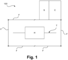
- a core module 100 is illustrated in a schematic plan view.
- the core module 100 comprises a handler H, a supply unit S, a control unit C and several interface frames or frame elements F.
- the interface frames F form the main part of the core module's 100 housing and are arranged in such a manner that the inner volume of the core module 100, in which the handler H is located, has a rectangular layout.
- a track T is provided within the housing of the core module 100 and positioned to be aligned in parallel with a longitudinal axis of the core module's 100 housing.
- the handler H is provided on the track T and is moveable in the direction of the longitudinal axis along the track T.
- the handler H may comprise, for example, a robotic element, e.g. a six-axes robotic arm, and a terminal manipulator, for example a gripper, or a plurality of grippers.
- the supply unit S is connected with the handler H and provides media such as purging gas(es) or pneumatic and/or hydraulic driving fluids and/or electric power to the handler H.
- the robotic arm may be powered electrically or pneumatically, and depending on the source of motion energy employed by the handler H, the supply unit S provides resources accordingly.
- the control unit C is in communicating connection with the handler H and controls the handler H.
- the control unit C can be provided in the form of a microcontroller or computer. It may send electronic signals to the robotic arm via dedicated wiring or through a wireless connection to control the movement of handler H.
- an apparatus 200 comprising the above described core module 100 and four functionality modules M1 to M4 is schematically depicted.
- Each of the functionality modules M1 to M4 may provide a different functionality.
- functionality module M1 may be a load port for transferring an object from outside the apparatus 200 into the apparatus 200. This transfer is controlled by the control unit C of the core module 100.
- the handler H may then be controlled to move towards the load port M1 along the track T and take over the object from the load port M1.
- the handler H may further be controlled by the control unit C to transfer the object to the functionality module M2, which may be, for example, an inspection module for inspecting the object, e.g. optically.
- the functionality module M2 may be, for example, an inspection module for inspecting the object, e.g. optically.
- the object is then inspected by the inspection module M2.
- a camera and illumination system may be provided with the inspection module M2. Images of the object obtained during this inspection may be compared to images of a reference object of the same type in order to detect deviations.
- the reference images may be stored in the inspection module M2 or in the control unit C or may also be provided from outside the apparatus 200.
- the inspected object may be transferred by the handler H to a third functionality module M3, which, in this embodiment, is a cleaning module.
- the object is cleaned, for example, in order to remove particulate contaminants which led to the deviation detected by the inspection module M2.
- the inspection module M2 might have mapped the locations on the object in which deviations between the inspected and reference objects occurred so that the cleaning module M3 can be controlled by the control unit C to decontaminate those locations, particularly.
- the handler H may transfer the object back to the inspection module M2, where the result of the cleaning procedure can be assessed in the same manner as described above.
- the handler H may transfer the object to the fourth functionality module M4 which may be a storage module. This may also be the case for objects which the inspection module M2 deems clean after a decontamination treatment by the cleaning module M3.
- a sufficiently clean object may, thus, be stored in the storage module M4 without undergoing any cleaning procedure, while objects requiring decontamination treatment are not transferred to the storage module M4 until sufficient cleanness is achieved.
- This provides several advantages such as time saving, when e.g. not all the objects are cleaned before storing; decrease of wear, since every cleaning may cause mechanical or chemical stress to the object; and decrease of cross-contamination, as only substantially clean objects are stored in the storage module M4.
- Particularly advantageous embodiments enable the apparatus 200 to treat several objects simultaneously. For example, when a first object is being cleaned in the cleaning module M3, a second object may be retrieved from the storage module M4.
- the handler H will typically not be needed for cleaning the first object, so it is idle during the cleaning procedure and can therefore be used to transport the second object from the storage module M4 to the load port M1.
- Another possibility for such simultaneous handling may be that a first object is cleaned in the cleaning module M3 while a second object is inspected by the inspection module M2. If the second object is deemed to be sufficiently clean, it can be moved to the storage module M4 by the handler H, before the first object is transferred back to the inspection module M3 for assessment of the cleaning result.
- the second object is also deemed to require cleaning treatment
- the first object may be removed from the cleaning module M3 after the cleaning procedure has finished. it cannot be transferred to the inspection module M2 directly, because that is still occupied by the second object. Therefore, the first object may be moved to a parking position, e.g. the load port M1, by the handler H.
- the handler H then transports the second object from the inspection module M2 to the cleaning module M3 and subsequently the first object from the parking position (in this example the load port M1) to the inspection module M2.
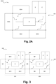
- FIG. 2A A second embodiment of an apparatus 200A according to the invention is described with reference to Fig. 2A .
- the apparatus 200A is provided with different functionality modules in comparison to the first embodiment.
- a receiving module M4A for receiving reticle shipping boxes is provided.
- a box handling module M2A is configured to open and close reticle transport boxes and a pod assembling module M3A is provided to assemble reticle double pods from their respective basic components as described in further detail below.
- a load port M1A is provided to transfer such double pods to and from outside the apparatus 200A, for example to and from a transport line which is in communication with an external terminal of the load port M1A.
- a reticle in the context of this disclosure may be understood as a photomask for a photolithographic process utilized for structuring semiconducting substrates such as silicon wafers to produce integrated circuits in the substrate material. Since these reticles are structured on a length scale of only several nanometers, they are costly to produce and of delicate stability. Therefore, special shipping boxes are used to transfer them safely from one factory to another and special containers, called pods, are used to transport them within the production facility itself. The shipping boxes usually differ from the pods used within the production facility. In the case of the photolithographic process using extreme ultraviolet (EUV) light for irradiating the substrate to be structured, the pods utilized are usually double pods consisting of an inner pod (EIP) and an outer pod (EOP).
- EUV extreme ultraviolet
- the reticle is accommodated within the EIP and the EIP is entirely surrounded by the EOP.
- Both the EIP and the EOP comprise two components, one upper and one lower component, each.
- the reticle and the EIP components are immobilized relative to one another through the interaction of the EOP with the EIP in order to prevent abrasion and thereby particle contamination of the reticle.
- the apparatus 200A of this second embodiment can be used.
- a reticle contained within a shipping box may be received at an outer terminal by the receiving module M4A.
- the receiving module M4A transfers the shipping box into the inner volume of the apparatus 200A, e.g. through an airlock in which the shipping box may be purged with a purging fluid or gas such as nitrogen.
- the handler H transfers the shipping box from the receiving module M4A to the box handling module M2A, where the box is opened. Since the shipping box has a substantially different shape and material in comparison to the reticle contained within it, a different terminal manipulator of the handler H might be necessary for the handling of the reticle than for the handling of the shipping box.
- the handler H may therefore be equipped with several different terminal manipulators, each of which is adapted to handling a different type of object.
- the handler may be equipped with three different terminal manipulators: a first one for handling shipping boxes, a second one for handling bare reticles and a third one for handling double pods.
- the handler H may, thus, using the second terminal manipulator, move the bare reticle previously contained within the reticle shipping box from the box handling module M2A to the pod assembling module M3A.
- the pod assembling module M3A then assembles a double pod around the reticle.
- the two lower components of the EOP and the EIP respectively may be provided with the pod assembling module M3A before the handler H delivers the bare reticle.
- the reticle is then placed into the lower component of the EIP and the upper components of the EIP and the EOP are attached to the respective lower components by the pod assembling module M3A.
- the double pod assembled in this way may then be moved by the handler H using its third terminal manipulator to the load port M1A, which transfers the double pod, e.g. through an airlock, to an outer terminal of the load port M1A.
- the double pod may then be collected from the outer terminal of the load port M1A by the above mentioned transport line, which in this embodiment does not form part of the apparatus 200A.
- the different terminal manipulators are not permanently attached to the robotic arm of the handler H, but are, for example, provided in a manipulator stocker, which may be an additional module mounted to one of the interface frames F of the core module 100.
- the handler after delivering the shipping box to the box handling module M2A, moves its terminal manipulator to the manipulator stocker, where the first manipulator is detached from the robotic arm of the handler H and stored within the manipulator stocking module.
- the second terminal manipulator is then attached to the robotic arm of the handler H by the manipulator stocking module in order to enable the handler H to handle bare reticles.
- the handler H subsequently transfers the bare reticle from the box handling module M2A to the pod assembling module M3A and returns to the manipulator stocking module to exchange the second terminal manipulator for the third one. With the then equipped third terminal manipulator, the handler H collects the double pod assembled by the pod assembling module M3A and transfers it to the load port M1A.
- This alternative embodiment using exchangeable terminal manipulators provides the advantage that less weight needs to be supported by the robotic arm of the handler H, which can therefore be designed smaller with the usual benefits of reduced cost and higher operating precision.
- the same apparatus 200A of the second embodiment can also be used in the opposite direction to receive a reticle from within the production facility, retrieve it from the double pod in which it is contained and box it in a shipping box to transfer it to a different factory, for example.
- the apparatus 300 of this embodiment is a cleaning apparatus 300 for cleaning double pods and comprises an outer pod or EOP cleaner 310 and an inner pod or EIP cleaner 320, each of which comprise one core module 100 as described above.
- the two core modules 100 are connected to one another through one of the functionality modules M5, which is attached to one interface frame 100 of each of the two core modules 100.
- One functionality module M1 of the EOP cleaner 310 is a load port which may be essentially the same as in the second embodiment and is configured to receive double pods as described above.
- a double pod received at the load port M1 is empty (does not contain a reticle).
- the handler H of the core module 100 of the EOP cleaner 310 at which the load port M1 is provided transfers the double pod from the load port M1 to the functionality module M5, which is a separation module with similar functionality as the pod assembling module M3 of the second embodiment.
- the double pod is disassembled or opened, so that upper and lower EOP components are separable from upper and lower EIP components.
- the handler H of the EOP cleaner 310 moves the EOP components to an upper EOP component cleaning module M12 and a lower EOP component cleaning module M13, respectively, where the EOP components are cleaned by the respective module M12, M13.
- An EOP inspection module M14 may be additionally provided to assess the result of the EOP cleaning procedure.
- the upper and lower EIP components are consecutively moved to respective upper M7 and lower M8 EIP component cleaning modules which form part of the EIP cleaner 320 by the EIP cleaner's 320 handler H.
- the upper EIP component cleaning module M7 then cleans the upper EIP component and the lower EIP component cleaner cleans the lower EIP component.
- An EIP inspection module M6 may be provided with similar functionality as described above referring to the EOP inspection module M14.
- the reassembled double pod comprising an EIP contained within an EOP is returned to the load port M1 attached to the EOP cleaner 310, where the double pod is transferred to an outside terminal of the load port M1, for example through an airlock.
- the handler H of the EIP cleaner 320 may be configured to support substantially less weight than the handler H of the EOP cleaner 310, since it only needs to handle single components of the EIP, whereas the handler H of the EOP cleaner 310 in this third embodiment must be configured to carry the weight of an entire double pod.
- One important advantage of the described configuration of the double pod cleaning apparatus 300 is that the EIP components, which usually are substantially cleaner than the EOP, are handled by a dedicated handler H of the EIP cleaner 320. Thereby, cross contamination from the outer surface of the EOP to the EIP is effectively prevented.
- An alternative for this apparatus 300 according to the third embodiment may be provided with an additional reticle storing module, where reticles contained within the double pod prior to cleaning may be stored during the pod cleaning procedure.
- This reticle storing module is advantageously provided with the EIP cleaner 320, as the internal environment of the EIP cleaner 320 is substantially less contaminated, especially with particles, than the internal environment of the EOP cleaner 310.
- double pods containing a reticle may also be cleaned. It is also possible to further integrate a reticle cleaner into the cleaning apparatus 300, which is advantageous because freshly cleaned reticles would then be returned to also freshly cleaned double pods, thus further improving the overall cleanness of the respective components.
- double pod cleaning apparatus 400 comprises an EOP cleaner 410 and an EIP cleaner 420, each comprising a core module 100 with a handler H.
- the handlers H of the EOP 410 and EIP 420 cleaners are optionally moveable on a track T.
- a track T may not be necessary in cases where the handler H is configured to reach all the relevant areas of the respective cleaner 410, 420 without lateral movement.
- handlers H may advantageously be configured for rotational movement about a stationary vertical axis. This is particularly advantageous as lateral movements of robotic devices are generally slow in comparison to rotational movements.
- the double pod cleaner 400 further comprises an assembler 430 with a further core module 100 and handler H supported on a linear track T.
- the assembler 430 is provided with a receiving load port M40, an assembly station M44 and an exit load port M47.
- an arriving double pod is received at the receiving load port M40, which comprises an airlock.
- the double pod is passed through the airlock of receiving load port M40 and moved to the assembly station M44 by the handler H.
- the assembly station M44 the functionality of which essentially corresponds to that of the separation module M5 described above, the double pod is opened and EOP components are transferred to the EOP cleaner 410, while the EIP is transferred to the EIP cleaner 420.
- the upper EOP component is transferred to the EOP cleaner 410.
- the EIP is transferred to the EIP cleaner 420, preferably as a whole, so that the inside of the EIP is not exposed to the relatively contaminated atmosphere of the assembler 430.
- the lower component of the EOP is transferred to the EOP cleaner 410.
- the transfer of the EOP components and the EIP to the respective cleaners 410, 420 can, for example, be performed via respective transfer modules M43 or by a hand-over procedure in which the handler H of the assembler 430 transports the respective object to be transferred to the respective interface frame F, at which the assembler is connected to the respective cleaner 410, 420.
- the handler H of the respective cleaner collects the respective object from the handler H of the assembler 430.
- the latter is particularly favorable in terms of space requirement, but necessitates careful synchronization of the involved handlers H, whereas the former is more flexible regarding the timing of operation of the handlers H.
- Each cleaner 410, 420 comprises an entry buffer M45 for temporarily storing uncleaned EOP or EIP components, respectively.
- the entry buffers M45 may also function as transfer modules M43.
- the handler H of the assembler 430 may deliver the respective object to be cleaned directly to the respective entry buffer M45.
- Each cleaner 410, 420 is provided with at least one cleaning module M41 and at least one drying module M42.
- the drying modules M42 are positioned above the cleaning modules M41, thereby reducing the overall lateral spatial footprint of the apparatus 400.
- the cleaning module M41 may, for example, comprise means for mechanical particle removal and/or for providing a fluid jet.
- the fluid may be provided, for example, in the form of a liquid such as deionized water or an organic solvent and/or in the form of a gas like nitrogen, carbon dioxide or purified air (e.g. so-called "extreme clean dry air” (XCDA)).
- Mechanical cleaning means may e.g. comprise brushes, wipers or a so-called "sticky finger".
- the drying module M42 may be operated under vacuum or reduced pressure, for example, at an absolute pressure in the range of 1 kPa to 90 kPa, particularly between 10 kPa and 50 kPa, e.g. at about 25 kPa.
- the drying module M42 may further comprise heating means such as an infrared light source or a convection heater configured to heat an internal atmosphere of the drying module M42 and/or the cleaned object to a temperature in the range of 30 °C to 120 °C, especially between 50 °C and 90 °C, e.g. approximately 65 °C.
- the temperature and/or pressure in the drying module M42 are controlled, e.g. in a closed feedback loop.
- a dryness parameter is also monitored in order to determine when an object is sufficiently dry for removal from the drying module M42.
- Each of the cleaners 410, 420 further comprises at least one exit buffer M46 for temporarily storing clean EOP or EIP components, respectively.
- the entry buffer M45 is used as the transfer module M43, it is advantageous to position the exit buffer M46 above or below the entry buffer M45, as indicated in Fig. 4 .
- the transfer module M43 may comprise an entry buffer M45 and an exit buffer M46.
- Operation of the two cleaners 410, 420 can be provided in an essentially identical manner.
- the handler H moves an uncleaned object, i.e. an EOP or EIP component from the entry buffer M45 to one of the at least one cleaning module M41.
- the respective object is then cleaned in the cleaning module M41 and afterwards transferred to the drying module M42 using the handler H.
- the handler H collects the clean and dry component from the cleaning module M42 and transfers it to an exit buffer M46 where the object is stored until all of the components necessary for reassembling the double pod are clean and dried.
- the handler H of the assembler 430 collects the lower component of the EOP from the exit buffer M46 of the EOP cleaner 410 and transfers it to the assembly station M44.
- the handler H then collects the EIP from the exit buffer M46 of the EIP cleaner 420 and places it onto the lower component of the EOP in the assembly station M44.
- the handler collects the upper component of the EOP from the exit buffer M46 of the EOP cleaner 410 and closes the double pod placing the upper component onto the lower component and attaching the two components of the EOP to one another.
- the assembled clean double pod is then transferred to the exit load port M47 through which it leaves the cleaning apparatus 400, preferably through another airlock provided with the exit load port M47.
- the handler H of the assembler should be configured to be capable of lifting at least 2.5 kg of weight.
- the handlers H of the respective cleaners 410, 420 may be capable of lifting only a fraction of that, since they are only required to simultaneously lift only one component of an EOP or EIP, respectively. It is therefore typically not required for the handler H of the EIP cleaner 420 to be capable of lifting more than about 0.6 kg, while the handler H of the EOP cleaner should be capable of lifting around 0.75 kg of weight.
- both handlers H of the cleaners 410, 420 need to perform much more complex movements than the handler H of the assembler 430. Therefore, it may be necessary for the handlers H of the cleaners 410, 420 to be provided with six axes or degrees of freedom, each, while the handler H of the assembler can be provided in the form of a three-axes-robot.
- the EIP may be pre-assembled in the exit buffer M46 after drying of its components, so that the handler H of the assembler 430 can collect the EIP as a whole so as to prevent contamination of the EIP's inner volume. This can be accomplished relatively easily since assembling an EIP from its components typically involves no locking or fixing and comprises only placing the upper component onto the lower component.
- the handlers H may be provided with several interchangeable terminal manipulators, each of which is adapted to a specific task the respective handler H needs to carry out.
- the interface frames F are not necessarily all provided on the same horizontal level, but could also be provided in several levels stacked one above the other so as to use more vertical space.
- the handler H or the track T supporting the handler H may be supported on an elevating element in order to reach the respective functionality modules on the upper levels.
Landscapes
- Container, Conveyance, Adherence, Positioning, Of Wafer (AREA)
- Engineering & Computer Science (AREA)
- Robotics (AREA)
- Crystals, And After-Treatments Of Crystals (AREA)
- Moulds For Moulding Plastics Or The Like (AREA)
- Die Bonding (AREA)
Claims (14)
- Kernmodul (100) für Halbleiterproduktionsanlagen, wobei das Kernmodul (100) Folgendes umfassteine Versorgungseinheit (S),eine Steuereinheit (C),eine von der Steuereinheit (C) gesteuerte Handhabungseinrichtung (H), undeine Vielzahl von rechteckigen Schnittstellenrahmen (F), wobei jeder Schnittstellenrahmen (F)an mindestens einem weiteren der Vielzahl von Schnittstellenrahmen (F) anbringbar und von diesem abnehmbar ist, unddazu konfiguriert ist, eine Blindplatte oder ein Funktionsmodul (M...) aufzunehmen oder zu halten,wobei die Versorgungseinheit (S) mit jedem oder mindestens einem der Vielzahl von Schnittstellenrahmen (F) verbindbar ist, um Medien und elektrische Energie für ein jeweiliges Funktionsmodul (M...) bereitzustellen, unddie Steuereinheit (C) so konfiguriert ist, dass sie jedes oder mindestens eines der Funktionsmodule (M...) steuert, die in einem der mehreren Schnittstellenrahmen (F) untergebracht sind oder von diesen gehalten werden.
- Kernmodul (100) nach Anspruch 1, wobei ein Innenvolumen des Kernmoduls (100), in dem sich zumindest die Handhabungseinrichtung (H) befindet, gegen die das Kernmodul (100) umgebende Atmosphäre abgedichtet ist.
- Kernmodul (100) nach Anspruch 1 oder 2, wobei die laterale Größe jedes Schnittstellenrahmens (F) einem ganzzahligen Vielfachen einer vordefinierten Grundrahmengröße entspricht.
- Kernmodul (100) nach einem der vorhergehenden Ansprüche, wobei mehrere oder alle der Vielzahl von Schnittstellenrahmen (F) in Größe und Form identisch sind.
- Kernmodul (100) nach einem der vorhergehenden Ansprüche, wobei die Handhabungseinrichtung (H) einen Endmanipulator und ein Roboterelement umfasst, das aus der Gruppe eines sechsachsigen Roboterarms, eines vierachsigen Roboterarms, eines SCARA und einer Wafermaschine ausgewählt ist, wobei der Endmanipulator an dem Roboterelement angebracht und/oder von diesem abgenommen werden kann und so konfiguriert ist, dass er mechanisch mit einem zu handhabenden Objekt interagiert.
- Kernmodul (100) nach Anspruch 5, wobei das zu handhabende Objekt eines oder mehrere von einem Retikel, einem Retikelbehälter, einem Halbleiterchip, einem Wafer und/oder einem Waferbehälter oder Komponenten davon umfasst.
- Kernmodul (100) nach einem der vorhergehenden Ansprüche, das ferner eine einachsige Schiene (T) umfasst, die so konfiguriert ist, dass sie die Handhabungseinrichtung (H) trägt, wobei die Handhabungseinrichtung (H) entlang der Schiene (T) beweglich ist, und die Steuereinheit (C) so konfiguriert ist, dass sie die Bewegung der Handhabungseinrichtung (H) entlang der Schiene (T) steuert.
- Kernmodul (100) nach einem der vorhergehenden Ansprüche, wobei die mehreren Schnittstellenrahmen (F) so angeordnet sind, dass ein Gehäuse des Kernmoduls (100) gebildet wird, das einen allgemein rechteckigen Grundriss aufweist.
- Kernmodul (100) nach einem der vorhergehenden Ansprüche, ferner umfassend eine Spüleinrichtung, die so konfiguriert ist, dass sie einen laminaren Gasstrom durch das Innenvolumen des Kernmoduls (100) bereitstellt, wobei die Spüleinrichtung vorzugsweise mit der Versorgungseinheit (S) und/oder der Steuereinheit (C) verbunden ist.
- Vorrichtung (200, 200A, 300, 400) zur Handhabung eines Objekts, umfassend mindestens ein Kernmodul (100) nach einem der vorhergehenden Ansprüche und mindestens ein Funktionsmodul (M...).
- Vorrichtung (200, 200A, 300, 400) nach Anspruch 10, wobei das mindestens eine Funktionsmodul (M...) so konfiguriert ist, dass es eine Behandlung des Objekts bereitstellt, wobei die Behandlung eines oder mehrere der folgenden Elemente umfasst: Öffnen, Schließen, Verpacken, Lagern, Reinigen, Prüfen, Registrieren, Montieren, Reinigen, Aufbringen von Medien und Schreiben und/oder Lesen von Informationen.
- Vorrichtung (200, 200A, 300, 400) nach Anspruch 10 oder 11, wobei das mindestens eine Funktionsmodul (M...) mindestens ein Reinigungsmodul umfasst, das so konfiguriert ist, dass es Komponenten eines Doppelkapsel-Retikelbehälters reinigt, insbesondere mit einem Innenkapsel-Reinigungsmodul, das so konfiguriert ist, dass es Komponenten einer Innenkapsel der Doppelkapsel reinigt, und/oder einem Außenkapsel-Reinigungsmodul, das so konfiguriert ist, dass es Komponenten einer Außenkapsel der Doppelkapsel reinigt.
- Vorrichtung nach Anspruch 12, umfassend ein erstes und ein zweites Kernmodul (100), wobei das Außenkapsel-Reinigungsmodul an Schnittstellenrahmen des ersten Kernmoduls und das Innenkapsel-Reinigungsmodul an Schnittstellenrahmen des zweiten Kernmoduls angeordnet ist, wobei ein Ladezugang an einem Schnittstellenrahmen des ersten Kernmoduls angeordnet ist.
- Verfahren zum Betreiben einer Vorrichtung (200, 300) nach einem der Ansprüche 10 bis 13, das die folgenden Schritte umfasstBereitstellen und Identifizieren eines zu handhabenden Objekts,Identifizieren mindestens eines Funktionsmoduls (M...) zur Behandlung des Objekts,Bestimmen der Ausgangsposition der Handhabungseinrichtung (H),Steuern der Handhabungseinrichtung (H), um das Objekt zu behandeln, und Steuern des mindestens einen Funktionsmoduls (M...), zum Durchführen der Behandlung,wobei der Schritt des Steuerns der Handhabungseinrichtung (H) das Steuern der Handhabungseinrichtung (H) umfasst, dazu,sich auf das Objekt zuzubewegen,mechanisch mit dem Objekt zu interagieren, unddas Objekt an das mindestens eine Funktionsmodul (M...) zu übertragen.
Applications Claiming Priority (2)
| Application Number | Priority Date | Filing Date | Title |
|---|---|---|---|
| EP19217739 | 2019-12-18 | ||
| PCT/EP2020/086301 WO2021122654A1 (en) | 2019-12-18 | 2020-12-15 | Core module for semiconductor production facility machinery |
Publications (3)
| Publication Number | Publication Date |
|---|---|
| EP4078664A1 EP4078664A1 (de) | 2022-10-26 |
| EP4078664B1 true EP4078664B1 (de) | 2024-01-31 |
| EP4078664C0 EP4078664C0 (de) | 2024-01-31 |
Family
ID=68965732
Family Applications (1)
| Application Number | Title | Priority Date | Filing Date |
|---|---|---|---|
| EP20821304.1A Active EP4078664B1 (de) | 2019-12-18 | 2020-12-15 | Kernmodul für maschinen einer halbleiterherstellungsanlage |
Country Status (7)
| Country | Link |
|---|---|
| US (1) | US12288697B2 (de) |
| EP (1) | EP4078664B1 (de) |
| JP (1) | JP2023507098A (de) |
| KR (1) | KR20220131906A (de) |
| CN (1) | CN115280477A (de) |
| TW (1) | TWI896579B (de) |
| WO (1) | WO2021122654A1 (de) |
Family Cites Families (14)
| Publication number | Priority date | Publication date | Assignee | Title |
|---|---|---|---|---|
| US6848876B2 (en) | 2001-01-12 | 2005-02-01 | Asyst Technologies, Inc. | Workpiece sorter operating with modular bare workpiece stockers and/or closed container stockers |
| US20050183824A1 (en) * | 2004-02-25 | 2005-08-25 | Advanced Display Process Engineering Co., Ltd. | Apparatus for manufacturing flat-panel display |
| US20060201074A1 (en) | 2004-06-02 | 2006-09-14 | Shinichi Kurita | Electronic device manufacturing chamber and methods of forming the same |
| TWI269990B (en) | 2005-02-04 | 2007-01-01 | Univ Nat Cheng Kung | Quality prognostics system and method for manufacturing processes with generic embedded devices |
| US8419341B2 (en) | 2006-09-19 | 2013-04-16 | Brooks Automation, Inc. | Linear vacuum robot with Z motion and articulated arm |
| JP5097627B2 (ja) * | 2008-06-27 | 2012-12-12 | 株式会社日立ハイテクノロジーズ | 真空処理装置 |
| TWI458612B (zh) * | 2009-11-10 | 2014-11-01 | 因特瓦克公司 | 可作z軸運動並具多關節手臂之線性真空機械手 |
| KR101330990B1 (ko) * | 2011-03-03 | 2013-11-20 | 에이치아이티 주식회사 | 반도체 제조 설비 |
| US9646858B2 (en) | 2011-06-23 | 2017-05-09 | Brooks Automation, Inc. | Semiconductor cleaner systems and methods |
| WO2018075262A1 (en) | 2016-10-18 | 2018-04-26 | Mattson Technology, Inc. | Systems and methods for workpiece processing |
| KR101985763B1 (ko) * | 2016-11-24 | 2019-09-03 | 세메스 주식회사 | 기판 처리 장치 |
| GB201701166D0 (en) * | 2017-01-24 | 2017-03-08 | Picofluidics Ltd | An apparatus for electrochemically processing semiconductor substrates |
| CN108933097B (zh) * | 2017-05-23 | 2023-06-23 | 东京毅力科创株式会社 | 真空输送组件和基片处理装置 |
| JP6972852B2 (ja) * | 2017-05-23 | 2021-11-24 | 東京エレクトロン株式会社 | 真空搬送モジュール及び基板処理装置 |
-
2020
- 2020-12-15 US US17/756,938 patent/US12288697B2/en active Active
- 2020-12-15 CN CN202080087859.4A patent/CN115280477A/zh active Pending
- 2020-12-15 KR KR1020227024113A patent/KR20220131906A/ko not_active Ceased
- 2020-12-15 EP EP20821304.1A patent/EP4078664B1/de active Active
- 2020-12-15 WO PCT/EP2020/086301 patent/WO2021122654A1/en not_active Ceased
- 2020-12-15 JP JP2022535881A patent/JP2023507098A/ja active Pending
- 2020-12-18 TW TW109145040A patent/TWI896579B/zh active
Also Published As
| Publication number | Publication date |
|---|---|
| TW202129448A (zh) | 2021-08-01 |
| JP2023507098A (ja) | 2023-02-21 |
| US12288697B2 (en) | 2025-04-29 |
| CN115280477A (zh) | 2022-11-01 |
| EP4078664C0 (de) | 2024-01-31 |
| EP4078664A1 (de) | 2022-10-26 |
| WO2021122654A1 (en) | 2021-06-24 |
| TWI896579B (zh) | 2025-09-11 |
| KR20220131906A (ko) | 2022-09-29 |
| US20230017221A1 (en) | 2023-01-19 |
Similar Documents
| Publication | Publication Date | Title |
|---|---|---|
| KR101951911B1 (ko) | 반도체 스토커 시스템들 및 방법들 | |
| KR910006968B1 (ko) | 웨이퍼 형상 캐리어 지그를 사용한 생산시스템 | |
| US20080251473A1 (en) | Apparatus for storing contamination-sensitive flat articles, in particular for storing semiconductor wafers | |
| JP5193220B2 (ja) | ワークピースストッカ用の取外し可能なコンパートメント | |
| US20140294546A1 (en) | Removable compartments for workpiece stocker | |
| TW201601875A (zh) | 基板處理裝置 | |
| EP4078664B1 (de) | Kernmodul für maschinen einer halbleiterherstellungsanlage | |
| US20240100714A1 (en) | Method and apparatus for processing a substrate in cleaning modules | |
| TWI819815B (zh) | 加工裝置以及加工品的製造方法 | |
| KR20190140336A (ko) | 실링 부재 교체형 게이트 밸브 시스템과, 실링 플레이트 및 실링 플레이트용 매거진 |
Legal Events
| Date | Code | Title | Description |
|---|---|---|---|
| STAA | Information on the status of an ep patent application or granted ep patent |
Free format text: STATUS: UNKNOWN |
|
| STAA | Information on the status of an ep patent application or granted ep patent |
Free format text: STATUS: THE INTERNATIONAL PUBLICATION HAS BEEN MADE |
|
| PUAI | Public reference made under article 153(3) epc to a published international application that has entered the european phase |
Free format text: ORIGINAL CODE: 0009012 |
|
| STAA | Information on the status of an ep patent application or granted ep patent |
Free format text: STATUS: REQUEST FOR EXAMINATION WAS MADE |
|
| 17P | Request for examination filed |
Effective date: 20220525 |
|
| AK | Designated contracting states |
Kind code of ref document: A1 Designated state(s): AL AT BE BG CH CY CZ DE DK EE ES FI FR GB GR HR HU IE IS IT LI LT LU LV MC MK MT NL NO PL PT RO RS SE SI SK SM TR |
|
| DAV | Request for validation of the european patent (deleted) | ||
| DAX | Request for extension of the european patent (deleted) | ||
| GRAP | Despatch of communication of intention to grant a patent |
Free format text: ORIGINAL CODE: EPIDOSNIGR1 |
|
| STAA | Information on the status of an ep patent application or granted ep patent |
Free format text: STATUS: GRANT OF PATENT IS INTENDED |
|
| INTG | Intention to grant announced |
Effective date: 20230712 |
|
| GRAS | Grant fee paid |
Free format text: ORIGINAL CODE: EPIDOSNIGR3 |
|
| GRAA | (expected) grant |
Free format text: ORIGINAL CODE: 0009210 |
|
| STAA | Information on the status of an ep patent application or granted ep patent |
Free format text: STATUS: THE PATENT HAS BEEN GRANTED |
|
| AK | Designated contracting states |
Kind code of ref document: B1 Designated state(s): AL AT BE BG CH CY CZ DE DK EE ES FI FR GB GR HR HU IE IS IT LI LT LU LV MC MK MT NL NO PL PT RO RS SE SI SK SM TR |
|
| REG | Reference to a national code |
Ref country code: GB Ref legal event code: FG4D Ref country code: CH Ref legal event code: EP |
|
| REG | Reference to a national code |
Ref country code: DE Ref legal event code: R096 Ref document number: 602020025073 Country of ref document: DE |
|
| REG | Reference to a national code |
Ref country code: IE Ref legal event code: FG4D |
|
| U01 | Request for unitary effect filed |
Effective date: 20240216 |
|
| U07 | Unitary effect registered |
Designated state(s): AT BE BG DE DK EE FI FR IT LT LU LV MT NL PT SE SI Effective date: 20240227 |
|
| PG25 | Lapsed in a contracting state [announced via postgrant information from national office to epo] |
Ref country code: IS Free format text: LAPSE BECAUSE OF FAILURE TO SUBMIT A TRANSLATION OF THE DESCRIPTION OR TO PAY THE FEE WITHIN THE PRESCRIBED TIME-LIMIT Effective date: 20240531 |
|
| PG25 | Lapsed in a contracting state [announced via postgrant information from national office to epo] |
Ref country code: GR Free format text: LAPSE BECAUSE OF FAILURE TO SUBMIT A TRANSLATION OF THE DESCRIPTION OR TO PAY THE FEE WITHIN THE PRESCRIBED TIME-LIMIT Effective date: 20240501 |
|
| PG25 | Lapsed in a contracting state [announced via postgrant information from national office to epo] |
Ref country code: HR Free format text: LAPSE BECAUSE OF FAILURE TO SUBMIT A TRANSLATION OF THE DESCRIPTION OR TO PAY THE FEE WITHIN THE PRESCRIBED TIME-LIMIT Effective date: 20240131 Ref country code: RS Free format text: LAPSE BECAUSE OF FAILURE TO SUBMIT A TRANSLATION OF THE DESCRIPTION OR TO PAY THE FEE WITHIN THE PRESCRIBED TIME-LIMIT Effective date: 20240430 |
|
| PG25 | Lapsed in a contracting state [announced via postgrant information from national office to epo] |
Ref country code: ES Free format text: LAPSE BECAUSE OF FAILURE TO SUBMIT A TRANSLATION OF THE DESCRIPTION OR TO PAY THE FEE WITHIN THE PRESCRIBED TIME-LIMIT Effective date: 20240131 |
|
| PG25 | Lapsed in a contracting state [announced via postgrant information from national office to epo] |
Ref country code: RS Free format text: LAPSE BECAUSE OF FAILURE TO SUBMIT A TRANSLATION OF THE DESCRIPTION OR TO PAY THE FEE WITHIN THE PRESCRIBED TIME-LIMIT Effective date: 20240430 Ref country code: NO Free format text: LAPSE BECAUSE OF FAILURE TO SUBMIT A TRANSLATION OF THE DESCRIPTION OR TO PAY THE FEE WITHIN THE PRESCRIBED TIME-LIMIT Effective date: 20240430 Ref country code: IS Free format text: LAPSE BECAUSE OF FAILURE TO SUBMIT A TRANSLATION OF THE DESCRIPTION OR TO PAY THE FEE WITHIN THE PRESCRIBED TIME-LIMIT Effective date: 20240531 Ref country code: HR Free format text: LAPSE BECAUSE OF FAILURE TO SUBMIT A TRANSLATION OF THE DESCRIPTION OR TO PAY THE FEE WITHIN THE PRESCRIBED TIME-LIMIT Effective date: 20240131 Ref country code: GR Free format text: LAPSE BECAUSE OF FAILURE TO SUBMIT A TRANSLATION OF THE DESCRIPTION OR TO PAY THE FEE WITHIN THE PRESCRIBED TIME-LIMIT Effective date: 20240501 Ref country code: ES Free format text: LAPSE BECAUSE OF FAILURE TO SUBMIT A TRANSLATION OF THE DESCRIPTION OR TO PAY THE FEE WITHIN THE PRESCRIBED TIME-LIMIT Effective date: 20240131 |
|
| PG25 | Lapsed in a contracting state [announced via postgrant information from national office to epo] |
Ref country code: PL Free format text: LAPSE BECAUSE OF FAILURE TO SUBMIT A TRANSLATION OF THE DESCRIPTION OR TO PAY THE FEE WITHIN THE PRESCRIBED TIME-LIMIT Effective date: 20240131 |
|
| PG25 | Lapsed in a contracting state [announced via postgrant information from national office to epo] |
Ref country code: PL Free format text: LAPSE BECAUSE OF FAILURE TO SUBMIT A TRANSLATION OF THE DESCRIPTION OR TO PAY THE FEE WITHIN THE PRESCRIBED TIME-LIMIT Effective date: 20240131 |
|
| PG25 | Lapsed in a contracting state [announced via postgrant information from national office to epo] |
Ref country code: SM Free format text: LAPSE BECAUSE OF FAILURE TO SUBMIT A TRANSLATION OF THE DESCRIPTION OR TO PAY THE FEE WITHIN THE PRESCRIBED TIME-LIMIT Effective date: 20240131 |
|
| PG25 | Lapsed in a contracting state [announced via postgrant information from national office to epo] |
Ref country code: CZ Free format text: LAPSE BECAUSE OF FAILURE TO SUBMIT A TRANSLATION OF THE DESCRIPTION OR TO PAY THE FEE WITHIN THE PRESCRIBED TIME-LIMIT Effective date: 20240131 |
|
| PG25 | Lapsed in a contracting state [announced via postgrant information from national office to epo] |
Ref country code: SK Free format text: LAPSE BECAUSE OF FAILURE TO SUBMIT A TRANSLATION OF THE DESCRIPTION OR TO PAY THE FEE WITHIN THE PRESCRIBED TIME-LIMIT Effective date: 20240131 |
|
| PG25 | Lapsed in a contracting state [announced via postgrant information from national office to epo] |
Ref country code: SM Free format text: LAPSE BECAUSE OF FAILURE TO SUBMIT A TRANSLATION OF THE DESCRIPTION OR TO PAY THE FEE WITHIN THE PRESCRIBED TIME-LIMIT Effective date: 20240131 Ref country code: SK Free format text: LAPSE BECAUSE OF FAILURE TO SUBMIT A TRANSLATION OF THE DESCRIPTION OR TO PAY THE FEE WITHIN THE PRESCRIBED TIME-LIMIT Effective date: 20240131 Ref country code: RO Free format text: LAPSE BECAUSE OF FAILURE TO SUBMIT A TRANSLATION OF THE DESCRIPTION OR TO PAY THE FEE WITHIN THE PRESCRIBED TIME-LIMIT Effective date: 20240131 Ref country code: CZ Free format text: LAPSE BECAUSE OF FAILURE TO SUBMIT A TRANSLATION OF THE DESCRIPTION OR TO PAY THE FEE WITHIN THE PRESCRIBED TIME-LIMIT Effective date: 20240131 |
|
| REG | Reference to a national code |
Ref country code: DE Ref legal event code: R097 Ref document number: 602020025073 Country of ref document: DE |
|
| PLBE | No opposition filed within time limit |
Free format text: ORIGINAL CODE: 0009261 |
|
| STAA | Information on the status of an ep patent application or granted ep patent |
Free format text: STATUS: NO OPPOSITION FILED WITHIN TIME LIMIT |
|
| 26N | No opposition filed |
Effective date: 20241101 |
|
| U20 | Renewal fee for the european patent with unitary effect paid |
Year of fee payment: 5 Effective date: 20241227 |
|
| PG25 | Lapsed in a contracting state [announced via postgrant information from national office to epo] |
Ref country code: MC Free format text: LAPSE BECAUSE OF FAILURE TO SUBMIT A TRANSLATION OF THE DESCRIPTION OR TO PAY THE FEE WITHIN THE PRESCRIBED TIME-LIMIT Effective date: 20240131 |
|
| REG | Reference to a national code |
Ref country code: CH Ref legal event code: PL |
|
| GBPC | Gb: european patent ceased through non-payment of renewal fee |
Effective date: 20241215 |
|
| PG25 | Lapsed in a contracting state [announced via postgrant information from national office to epo] |
Ref country code: GB Free format text: LAPSE BECAUSE OF NON-PAYMENT OF DUE FEES Effective date: 20241215 |
|
| PG25 | Lapsed in a contracting state [announced via postgrant information from national office to epo] |
Ref country code: CH Free format text: LAPSE BECAUSE OF NON-PAYMENT OF DUE FEES Effective date: 20241231 |
|
| PG25 | Lapsed in a contracting state [announced via postgrant information from national office to epo] |
Ref country code: IE Free format text: LAPSE BECAUSE OF NON-PAYMENT OF DUE FEES Effective date: 20241215 |
|
| U20 | Renewal fee for the european patent with unitary effect paid |
Year of fee payment: 6 Effective date: 20251119 |