EP4078520B1 - Steuerung der sensoraktivierung und -deaktivierung zur energieeffizienten lokalisierung - Google Patents
Steuerung der sensoraktivierung und -deaktivierung zur energieeffizienten lokalisierung Download PDFInfo
- Publication number
- EP4078520B1 EP4078520B1 EP19831666.3A EP19831666A EP4078520B1 EP 4078520 B1 EP4078520 B1 EP 4078520B1 EP 19831666 A EP19831666 A EP 19831666A EP 4078520 B1 EP4078520 B1 EP 4078520B1
- Authority
- EP
- European Patent Office
- Prior art keywords
- sensors
- sensor
- localization
- confidence score
- features
- Prior art date
- Legal status (The legal status is an assumption and is not a legal conclusion. Google has not performed a legal analysis and makes no representation as to the accuracy of the status listed.)
- Active
Links
Images



Classifications
-
- H—ELECTRICITY
- H04—ELECTRIC COMMUNICATION TECHNIQUE
- H04N—PICTORIAL COMMUNICATION, e.g. TELEVISION
- H04N23/00—Cameras or camera modules comprising electronic image sensors; Control thereof
- H04N23/60—Control of cameras or camera modules
- H04N23/65—Control of camera operation in relation to power supply
- H04N23/651—Control of camera operation in relation to power supply for reducing power consumption by affecting camera operations, e.g. sleep mode, hibernation mode or power off of selective parts of the camera
-
- G—PHYSICS
- G06—COMPUTING OR CALCULATING; COUNTING
- G06T—IMAGE DATA PROCESSING OR GENERATION, IN GENERAL
- G06T7/00—Image analysis
- G06T7/70—Determining position or orientation of objects or cameras
- G06T7/73—Determining position or orientation of objects or cameras using feature-based methods
-
- G—PHYSICS
- G01—MEASURING; TESTING
- G01S—RADIO DIRECTION-FINDING; RADIO NAVIGATION; DETERMINING DISTANCE OR VELOCITY BY USE OF RADIO WAVES; LOCATING OR PRESENCE-DETECTING BY USE OF THE REFLECTION OR RERADIATION OF RADIO WAVES; ANALOGOUS ARRANGEMENTS USING OTHER WAVES
- G01S17/00—Systems using the reflection or reradiation of electromagnetic waves other than radio waves, e.g. lidar systems
- G01S17/88—Lidar systems specially adapted for specific applications
- G01S17/93—Lidar systems specially adapted for specific applications for anti-collision purposes
- G01S17/931—Lidar systems specially adapted for specific applications for anti-collision purposes of land vehicles
-
- G—PHYSICS
- G06—COMPUTING OR CALCULATING; COUNTING
- G06F—ELECTRIC DIGITAL DATA PROCESSING
- G06F1/00—Details not covered by groups G06F3/00 - G06F13/00 and G06F21/00
- G06F1/16—Constructional details or arrangements
- G06F1/1613—Constructional details or arrangements for portable computers
- G06F1/1626—Constructional details or arrangements for portable computers with a single-body enclosure integrating a flat display, e.g. Personal Digital Assistants [PDAs]
-
- G—PHYSICS
- G06—COMPUTING OR CALCULATING; COUNTING
- G06F—ELECTRIC DIGITAL DATA PROCESSING
- G06F1/00—Details not covered by groups G06F3/00 - G06F13/00 and G06F21/00
- G06F1/16—Constructional details or arrangements
- G06F1/1613—Constructional details or arrangements for portable computers
- G06F1/1633—Constructional details or arrangements of portable computers not specific to the type of enclosures covered by groups G06F1/1615 - G06F1/1626
- G06F1/1684—Constructional details or arrangements related to integrated I/O peripherals not covered by groups G06F1/1635 - G06F1/1675
-
- G—PHYSICS
- G06—COMPUTING OR CALCULATING; COUNTING
- G06F—ELECTRIC DIGITAL DATA PROCESSING
- G06F1/00—Details not covered by groups G06F3/00 - G06F13/00 and G06F21/00
- G06F1/16—Constructional details or arrangements
- G06F1/1613—Constructional details or arrangements for portable computers
- G06F1/1633—Constructional details or arrangements of portable computers not specific to the type of enclosures covered by groups G06F1/1615 - G06F1/1626
- G06F1/1684—Constructional details or arrangements related to integrated I/O peripherals not covered by groups G06F1/1635 - G06F1/1675
- G06F1/1694—Constructional details or arrangements related to integrated I/O peripherals not covered by groups G06F1/1635 - G06F1/1675 the I/O peripheral being a single or a set of motion sensors for pointer control or gesture input obtained by sensing movements of the portable computer
-
- G—PHYSICS
- G06—COMPUTING OR CALCULATING; COUNTING
- G06F—ELECTRIC DIGITAL DATA PROCESSING
- G06F1/00—Details not covered by groups G06F3/00 - G06F13/00 and G06F21/00
- G06F1/26—Power supply means, e.g. regulation thereof
- G06F1/32—Means for saving power
- G06F1/3203—Power management, i.e. event-based initiation of a power-saving mode
- G06F1/3206—Monitoring of events, devices or parameters that trigger a change in power modality
- G06F1/3215—Monitoring of peripheral devices
-
- G—PHYSICS
- G06—COMPUTING OR CALCULATING; COUNTING
- G06F—ELECTRIC DIGITAL DATA PROCESSING
- G06F1/00—Details not covered by groups G06F3/00 - G06F13/00 and G06F21/00
- G06F1/26—Power supply means, e.g. regulation thereof
- G06F1/32—Means for saving power
- G06F1/3203—Power management, i.e. event-based initiation of a power-saving mode
- G06F1/3234—Power saving characterised by the action undertaken
- G06F1/3287—Power saving characterised by the action undertaken by switching off individual functional units in the computer system
-
- G—PHYSICS
- G06—COMPUTING OR CALCULATING; COUNTING
- G06T—IMAGE DATA PROCESSING OR GENERATION, IN GENERAL
- G06T7/00—Image analysis
- G06T7/70—Determining position or orientation of objects or cameras
- G06T7/73—Determining position or orientation of objects or cameras using feature-based methods
- G06T7/74—Determining position or orientation of objects or cameras using feature-based methods involving reference images or patches
-
- H—ELECTRICITY
- H04—ELECTRIC COMMUNICATION TECHNIQUE
- H04N—PICTORIAL COMMUNICATION, e.g. TELEVISION
- H04N23/00—Cameras or camera modules comprising electronic image sensors; Control thereof
- H04N23/60—Control of cameras or camera modules
- H04N23/617—Upgrading or updating of programs or applications for camera control
-
- H—ELECTRICITY
- H04—ELECTRIC COMMUNICATION TECHNIQUE
- H04N—PICTORIAL COMMUNICATION, e.g. TELEVISION
- H04N23/00—Cameras or camera modules comprising electronic image sensors; Control thereof
- H04N23/60—Control of cameras or camera modules
- H04N23/65—Control of camera operation in relation to power supply
-
- H—ELECTRICITY
- H04—ELECTRIC COMMUNICATION TECHNIQUE
- H04N—PICTORIAL COMMUNICATION, e.g. TELEVISION
- H04N23/00—Cameras or camera modules comprising electronic image sensors; Control thereof
- H04N23/60—Control of cameras or camera modules
- H04N23/66—Remote control of cameras or camera parts, e.g. by remote control devices
- H04N23/661—Transmitting camera control signals through networks, e.g. control via the Internet
-
- G—PHYSICS
- G06—COMPUTING OR CALCULATING; COUNTING
- G06T—IMAGE DATA PROCESSING OR GENERATION, IN GENERAL
- G06T2207/00—Indexing scheme for image analysis or image enhancement
- G06T2207/10—Image acquisition modality
- G06T2207/10016—Video; Image sequence
-
- Y—GENERAL TAGGING OF NEW TECHNOLOGICAL DEVELOPMENTS; GENERAL TAGGING OF CROSS-SECTIONAL TECHNOLOGIES SPANNING OVER SEVERAL SECTIONS OF THE IPC; TECHNICAL SUBJECTS COVERED BY FORMER USPC CROSS-REFERENCE ART COLLECTIONS [XRACs] AND DIGESTS
- Y02—TECHNOLOGIES OR APPLICATIONS FOR MITIGATION OR ADAPTATION AGAINST CLIMATE CHANGE
- Y02D—CLIMATE CHANGE MITIGATION TECHNOLOGIES IN INFORMATION AND COMMUNICATION TECHNOLOGIES [ICT], I.E. INFORMATION AND COMMUNICATION TECHNOLOGIES AIMING AT THE REDUCTION OF THEIR OWN ENERGY USE
- Y02D10/00—Energy efficient computing, e.g. low power processors, power management or thermal management
Definitions
- the present disclosure relates to controlling multi-sensor operation during localization of a device.
- Localization and mapping algorithms such as Simultaneous Localization and Mapping (SLAM) algorithms
- SLAM Simultaneous Localization and Mapping
- Some localization and mapping algorithms utilize data from cameras and sometimes other types of sensors to increase robustness but can still fail to produce consistent maps in some environments. In visually degraded environments, e.g. dark room or tunnel, it is harder to extract useful information from a camera due to features being determined or recognized with a lower probability or not at all.
- Patent WO 2019/221582 A1 discloses a method to reduce power consumption in a SLAM based augmented reality system using a plurality of dynamic vision sensors. A process for activation/ deactivation is based on a confidence value of each camera attributed in dependence of the tracked features quality and number.
- Patent US 2014/011517 A1 discloses a method for energy-efficient location determination of a mobile computing device containing multiple sensors (camera, accelerometers, GPS).
- Patent US 2018/115711 A1 discloses a method to estimate a self-position reliably with lower power consumption, where the self-position is estimation is performed using a plurality of cameras.
- a method according to claim 1 is disclosed herein.
- the method selectively deactivates individual ones of the sensors within the subset of sensors based on a determination of whether their respective utilization of hardware resources satisfies a defined rule. In some other further embodiments, the method regulates the sampling rate and/or resolution of the sensors among the subset that are active, based on speed of the device.
- a device according to claim 4 is also disclosed herein.
- the device further includes a transceiver.
- the operations performed by the processor can further include communicating through the transceiver with a proximately located device.
- the confidence score for one of the sensors is determined based on obtaining a listing of sensors that are presently active for use by the proximately located device.
- a potential advantage that may be provided by these and other embodiments is that the deactivation and activation of sensors used for localization is controlled based on the individual confidence scores of the sensors, and can result in reduction in power consumption of the system and enable more optimized use of resources while continuing to satisfy ongoing localization performance requirements.
- Various embodiments herein are directed to controlling activation and deactivation of individual sensors considering power dissipation during data acquisition as well as the power consumed while processing the acquired data (CPU/GPU, memory, etc.) while performing localization or while performing combined localization and mapping (e.g., SLAM).
- power dissipation during data acquisition as well as the power consumed while processing the acquired data (CPU/GPU, memory, etc.) while performing localization or while performing combined localization and mapping (e.g., SLAM).
- SLAM combined localization and mapping
- Any state-of-the-art device performing SLAM (e.g., augmented reality/virtual reality headsets, smartphones, semi-autonomous vehicles, robots, etc.) operates with all of its transported sensors activated.
- the environment in which the device operates can be static, the lighting conditions and other parameters experienced by the sensors can cause SLAM algorithms to generate inconsistent maps. Therefore, it is important to not only equip the device with various different types of sensors and/or differently configured sensors, but also to utilize the sensors in a more optimal manner.
- Various embodiments herein are directed to dynamically adapting which sensors are activated and deactivated during localization operations and/or during combined localization and mapping operations based on confidence scores that are determined for the sensors at certain regions.
- Some further embodiments are directed to an efficient scheduling algorithm that determines a more optimal subset of sensors that are presently used for localization operations for a device within an environment, and which may be further used for mapping operations within the environment.
- an efficient scheduling algorithm that determines a more optimal subset of sensors that are presently used for localization operations for a device within an environment, and which may be further used for mapping operations within the environment.
- the scheduling algorithm responds to the effect of changes in the characteristics of the environment on the various sensors when determining which sensors are to be activated or deactivated.
- the scheduling algorithm can operate to provide reduced power consumption and thus extend localization or combined localization and mapping (e.g., SLAM) operational time, and can improve other system resource utilization (e.g., processor utilization, memory utilization, network utilization, etc.).
- the scheduling algorithm can also operate to identify which sensors are most important for use in a specific environment and, thereby, enable more effective selection of which sensors will be transported by a device in that environment.
- One embodiment of the scheduling algorithm is configured to assume the characteristics of the environment remain static over time. For instance, the algorithm may be configured to assume that lighting conditions most affect the confidence score of an RGB camera.
- a device carrying a RGB camera sensor is to perform SLAM in a basement environment having fixed lighting and with no sunlight interference.
- the algorithm can be configured to identify that the RGB camera is providing to be a good sensor because it tracks adequate features, which the algorithm can then determine is an indication that any device carrying an RGB camera of the same type and make should perform well within that environment.
- S corresponds to cardinality of set S.
- the state x i of each sensor s i can be either 0 (deactivated) or 1 (activated).
- a deactivated state of a sensor can correspond to setting its respective sampling rate to a lower rate or zero, and the activated state of the sensor can correspond to setting its sampling rate to an increased rate or default value based on the current dynamics of the device.
- a deactivated state of a sensor can correspond to setting its respective resolution to a lower resolution or zero, and the activated state of the sensor can correspond to setting its resolution to an increased resolution or default value (sufficient to support localization) based on the current dynamics of the device.
- the power e i consumed by each sensor s i is estimated considering both the power dissipation of the sensor during data acquisition, as well as the power consumed while processing the acquired data in the SLAM thread.
- Various embodiments herein select the most suitable combination of sensors based on their current performance at a certain region (performed online responsive to presently sensed condition), or upon their performance at a previous session stored in the SLAM map (performed offline).
- the system deactivates all non-selected sensors to reduce the total power consumption and other system resource utilization (e.g., processor utilization, memory utilization, network utilization, etc.).
- the localization and mapping algorithm which can run on a separate thread, utilizes only the activated sensors at any time.
- FIG. 1 illustrates a top view of a geographic map showing movement of a device between different regions and associated sensor activation/deactivation operations in accordance with some embodiments of the present disclosure.
- Figure 6 illustrates a flowchart of operations by a device performing localization using a set of sensors that are transported with the device in accordance with some embodiments of the present disclosure.
- operations by a device performing localization using a set of sensors that are transported with the device include determining 600 a confidence score ( ⁇ _i) for each of the sensors (Si) among the set of sensors.
- the operations defined 602 a subset of the sensors among the set of sensors that are to remain active based on their respective confidence scores satisfying a defined threshold, e.g., being equal to or above a defined threshold value.
- the subset of sensors is preferably a non-empty set to ensure at least one sensor remains active.
- the operations then deactivate 604 the sensors within the set of sensors having confidence scores that do not satisfy the defined threshold, e.g., being less than the defined threshold value.
- the deactivation operations include controlling power consumption by deactivated ones of the sensors.
- the operation to compare the confidence scores of the sensors to a defined threshold can mean that the confidence scores for each of the sensors is compared to the same threshold value or can mean that different sensors may be associated with different threshold values such the confidence scores for each sensor would be compared to the associated threshold value for that sensor.
- the term "defined threshold" can mean a single value or a set of values that are associated with a set of sensors.
- a geographic region A is illustrated where sensor A satisfies a performance rule
- another geographic region B is illustrated where sensor B satisfies the performance rule
- an overlap region A-B is illustrated where both sensors A and B satisfy the performance rule.
- a device transported sensors A and B is within region A, where only sensor A satisfies the performance rule, and outside region A-B sensor A actively feeds data to the localization algorithm or combined localization and mapping algorithm, e.g., SLAM algorithm, and sensor B is deactivated.
- the localization algorithm or combined localization and mapping algorithm e.g., SLAM algorithm
- sensor B When the device moves along path segment 1 from region A to region A-B, where sensors A and B both satisfy the performance rule, sensor B may be activated and sensor A may be deactivated depending upon the relative power consumption, localization performance, combined localization and mapping performance (e.g., SLAM performance), resource utilization, etc., of sensors A and B.
- sensor B As the device transporting moves along path segment 2 to region B and outside region A-B, sensor B actively feeds data to the localization algorithm or combined localization and mapping algorithm, e.g., SLAM algorithm, and sensor A is deactivated.
- Figure 2 illustrates a top view of a geographic map showing movement of a vehicle transporting a device 200 and a set of sensors 201 and 203 through an example environment.
- the device and sensors may be transported in other manners, such as by a human, robot, aircraft (e.g., drone), ship, etc.
- the device 200 can be, but is not limited to, a component of any of a smartphone, wearable computer, augmented reality headset, virtual reality headset, mixed reality headset, semi-autonomous or autonomous vehicle, drone, aircraft, robot, etc. Although only two sensors are illustrated is to be understood that the computing device may be used with any plural number of sensors that are configured to feed data to a SLAM algorithm.
- Example types of sensors include, but are not limited to, RGB camera, infrared camera, inertial measurement unit (IMU), radar sensor, light detection and ranging (LiDAR) sensor, acoustic ranging sensor, proximity sensor, GPS, and RF transceiver (e.g., 5G-radio).
- IMU inertial measurement unit
- LiDAR light detection and ranging
- acoustic ranging sensor proximity sensor
- GPS GPS
- RF transceiver e.g., 5G-radio
- the below methods for calculating the confidence scores of sensors and activating and deactivating sensors may be exemplified by the vehicle transporting the computing device 200, a first sensor 201 and a second sensor 203 along the path 209 (e.g., road) through an environment.
- the vehicle transports along the path 209 it performs various operations discussed in embodiments of the present disclosure.
- the first sensor 201 is determined by the computing device 200 to satisfy a defined rule which causes activation or keeping the first sensor 201 activated while the vehicle remains in the first region 205.
- the vehicle travels into a second region 207 where the computing device 200 determines that the first sensor 201 delivers a confidence score that does not satisfy a defined threshold, e.g., less than a defined threshold.
- a defined threshold e.g., less than a defined threshold.
- Two alternative operational embodiments can be triggered by the computing device 200.
- the unsatisfactory confidence score of the first sensor 201 causes all of the onboard sensors that were previously deactivated (in this case only the second sensor 203) to be reactivated and analyzed to determine which of the reactivated sensors yields confidence scores that satisfy the defined threshold.
- the operations refer to an available localization and mapping, e.g., SLAM map, data structure that identifies one or more sensors that were activated and provided satisfactory confidence scores in the past in the second region 207, and the operations responsively activate the one or more sensors.
- the operations can deactivate the first sensor 201 to reduce power consumption and conserve other system resources, e.g., processing, memory, communications, etc.
- the operations for controlling activation and deactivation of sensors used by a device for localization and/or combined localization and mapping are performed responsive to confidence scores which are determined for the sensors.
- the confidence score is a metric that indicates trustworthiness in the accuracy of data that can be provided by a sensor or a set of sensors at a location or in an environment having certain characteristics and/or features that are sensed by one or more of the sensors.
- the confidence score of a sensor is highly correlated to the performance of the localization algorithm or combined localization and mapping (e.g., SLAM algorithm) using data from the sensor. Operations that can be used to determine the confidence score of a sensor for use in localization processing or combined localization and mapping processing, e.g., SLAM processing, are explained below.
- the example equation is described in the context of detection of visual features and a sensor data stream, the disclosed operations for determining the confidence score can be used with any type of feature with a specified descriptor that is identifiable in sensor data.
- the confidence score for one of the sensors can be determined 600 based on a ratio of a number of inlier features to a total number of inlier and outlier features detected by the sensor.
- Each of the inlier features has characteristics that are consistent with a defined model, and each of the outlier features has characteristics that are inconsistent with the defined model.
- the sensor or data includes "inliers", i.e., data whose distribution can be operationally determined using a defined set of model parameters, but may also be subject to noise, and "outliers" which are data that do not fit the model.
- the outliers can occur, for example, from extreme values of the noise or from erroneous sensor measurements or incorrect hypotheses operations interpreting the sensor data.
- the operations for controlling activation and deactivation of a sensor retrieve the number of inliers and outliers for a number of consecutive frames of data from the sensor.
- the number of inliers and outliers may be determined by a feature tracking module (FTM) operating for each sensor, which can be an essential component of the localization algorithm or combined localization and mapping algorithm and therefore should not increase the computational overhead.
- FTM feature tracking module
- An FTM for a sensor, such as a camera can detect and track keypoints. The positions of features within the sensor data are keypoints within images from a camera sensor.
- Descriptors of keypoints may include, but are not limited to, Binary Robust Invariant Scalable Keypoints (BRISK), Fast Retina KeyPoints (FREAK), Speeded Up Robust Features (SURF), Scale-invariant Feature Transform (SIFT), Oriented FAST and Rotated BRIEF (ORB), Features from Accelerated Segment Test (FAST), Binary Robust Independent Elementary Features (BRIEF).
- BRISK Binary Robust Invariant Scalable Keypoints
- FREAK Fast Retina KeyPoints
- SURF Speeded Up Robust Features
- SIFT Scale-invariant Feature Transform
- ORB Scale-invariant Feature Transform
- FAST Binary Robust Independent Elementary Features
- Different descriptors can be used for different types of sensors (e.g.: depth kernel descriptors can be used for depth sensors).
- random sample consensus (RANSAC) is commonly used for geometric verification and outlier detection.
- the set of inliers and outliers of the tracked features can be calculated based on operations described in a publication Buczko, Martin & Willert, Volker, "How to Distinguish Inliers from Outliers in Visual Odometry for High-speed Automotive Applications” (2016) 10.1109/IVS.2016.7535429 .
- a 2D feature tracked in an image captured by a visual sensor can be operationally considered to be an outlier when the respective image registration fails to find the spatial transformation required for that feature to be matched in a sequence of images.
- An example of 2D feature tracking is illustrated in Figure 5.
- Figure 5 illustrates operations of a feature tracking algorithm for a SLAM system configured according to some embodiments of the present disclosure.
- a feature located at I(x,y) in sensor frame (t) is determined to subsequently move to location I(x+dx, y+dy) in sensor frame (t+dt).
- a 3D feature/segment detected in a point cloud created by a range sensor is operationally considered to be an outlier when the respective point cloud registration fails to find a spatial transformation required for that feature/segment to be matched in a sequence of point clouds.
- Inliers can be distinguished from outliers by operation of the RANSAC algorithm.
- An example algorithm that separates inliers and outliers among a set of matches between two images mapped by an affine transform is described in the publication Beckouche, Simon, et al. "Robust Outliers Detection in Image Point Matching.” 2011 IEEE International Conference on Computer Vision Workshops, 2011, pp. 180-187 .
- the confidence score is determined based on how oscillatory the position of the tracked features is between consecutive frames of sensor data. In one embodiment, the confidence score for one of the sensors is determined 600 based on an amount of oscillation that is determined to occur between positions of features within sensor data obtained in consecutive sampling frames. The amount of oscillation that is determined to occur in the position of a certain feature is tracked in consecutive frames of a sensor.
- the global 3D position of the feature should remain constant. If the mapping of the 2D position of the feature from consecutive frames onto the 3D space yields back 3D positions that fluctuate more than some threshold, that means the performance of the sensor is poor.
- the confidence score for one of the sensors is determined 600 based on a signal-to-noise ratio (SNR) of the sensor compared to a defined threshold.
- SNR signal-to-noise ratio
- the sampling rate of the sensor may be relatively slow compared to the dynamics of the device, so localization processing could fail to produce accurate results or combined localization and mapping processing operation could fail to produce consistent maps.
- the confidence score for one of the sensors is determined 600 based on determining localization of the sensor relative to a map defined by a data structure identifying local features that have been previously sensed by one or more sensors, and determining the confidence score for the one of the sensors based on whether the sensor presently senses the local features identified by the data structure defining the map.
- An existing map may be exploited to evaluate the set of sensors currently being used. For instance, if the device has managed to localize within an available map, but certain features in its surrounding are not observed as expected from the map, then this may be an indication that the set of sensors currently being used is, for various reasons (e.g., different lighting conditions, reflective surfaces, moving objects in the room, etc.), not suitable for the current environment.
- the confidence score for one of the sensors is determined 600 based on determining localization of the sensor relative to a map defined by a data structure identifying positions of local features, and determining the confidence score for the one of the sensors based on comparison of where the sensor identifies the positions of the local features to where the data structure identifies the positions of the local features.
- Landmarks with known geometry, dimensions, and position in the room may be used as partial ground truth which enables the operations to determine localization error as an estimate of error in the device's pose. The operations can use the localization error to determine confidence in the data from the sensor.
- the confidence score for one of the sensors is determined 600 based on localization of the sensor to locations within a map defined by a data structure which identifies performance of sensors at the locations. Performance for the sensor is retrieved from the data structure based on the localization to the locations within the map. The confidence score is then determined based on the retrieved performance.
- the data structure of the map may be stored in a networked data repository that is accessed by the operations.
- the operations to deactivate 604 a sensor may include one of triggering the sensor to transition to a lower power state and triggering power off of the sensor.
- the operations to deactivate 604 a sensor include setting a data sampling rate of the sensor to one of a reduced sampling rate and zero.
- a set of sensors, Sc are defined to remain active, where Sc ⁇ S B , based on their utilization of hardware resources and their overall confidence score.
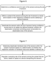
- the device selectively deactivates 700 individual ones of the sensors within the subset of sensors based on a determination of whether their respective utilization of hardware resources satisfies a defined rule.
- Example hardware resources can include, but are not limited to, any one or more of power consumption, processor utilization, memory utilization, and network communication utilization.
- the total number of combinations of activated sensors is 2
- Each combination ⁇ results in a utilization of hardware resources E ⁇ , and an overall confidence score ⁇ ⁇ ⁇ (0,1] can be defined so that homogeneity is penalized.
- the subset of the sensors is defined 602 to penalize inclusion of sensors that have more than a threshold level of similarity in operation. This penalty may depend on how disjunct parts of the environment two or more homogeneous sensors observe. The variety of different sensors enrich the representation of the surroundings using complementary information, and the precision of the measurements is improved by using redundant information. This step is completed in three sequential sub-steps:
- the overall confidence is the weighted average of the individual confidence scores where each weight w i depends on the frequency of occurrence of sensor s i in the combination ⁇ so that homogeneity is penalized.
- x i denotes the state of the sensor s i (0: idle, 1: active) in combination ⁇
- N denotes the total number of sensors on-board
- p is the penalizing factor (0 ⁇ p ⁇ 1)
- M i ⁇ Z + is the frequency of occurrence of sensor s i in combination ⁇ .
- a potential advantage is that these operations bias the set of active sensors to be more diversified in their operational characteristics, which can make the localization processing or combined localization and mapping processing have more robust performance as the device and sensors travel through environments having widely differing characteristics, e.g., ambient light brightness variations, light/RF surface reflectivity, recognizable surface feature density, feature ranges, sensed ambient noises, ambient interference, etc.
- the overall confidence ⁇ ⁇ score can be estimated based upon a machine learning (ML) algorithm where different combinations of sensors are used to evaluate the performance of the localization algorithm or combined localization and mapping algorithm, e.g., SLAM algorithm. After collecting significant amount of data from several sensors for different regions within a given environment, the overall confidence score of each combination for specific regions can be evaluated with greater accuracy. These operations can function to generate a performance profile for each sensor correlated with different geographic regions.
- ML machine learning
- the operations for the device select the most suitable set of sensors Sc based upon the set of sensors which are currently being used by its nearest neighbor device (collaborative localization or collaborative combined localization and mapping). This saves resources and time, as the operations do not need to evaluate the device's own sensors' performance in an online fashion, since it trusts its nearest neighbor device's decisions assuming the neighbor device's sensors have the same or sufficiently similar operational characteristics, e.g. same sensor type and manufacturer, as those being transported by the device.
- the operations select the most suitable set of sensors Sc based upon the overall confidence score ⁇ ⁇ stored from previous sessions for different regions.
- the map generated from the combined localization and mapping algorithm e.g., SLAM algorithm, is split into grids, and in each grid the overall confidence score ⁇ ⁇ for each combination ⁇ is stored. This way, in future sessions of the same or a different operations of a device, if the performance of the currently activated sensors degrades, the operations will directly activate the most suitable set of sensors by retrieving their overall confidence score ⁇ ⁇ from the grid the device is moving towards, and will accordingly deactivate the poorly performing sensors. This will save power since there is no need to activate the entire set of the on-board sensors for online evaluation.
- the operations may regulate 702 a sampling rate of the sensors among the subset that are active, based on speed of the device transporting the sensors. In other words, if the confidence score of sensor Si is above a predefined threshold, and if the dynamics of the device carrying the sensor payload are slow, then its respective sampling rate is decreased in a way that the confidence score remains beyond a certain value.
- fast/slow dynamics is application-dependent.
- the operations can be performed at higher sensor sampling rates so that enough information is captured by the sensors to characterize the environment.
- the sampling rate of the sensors can accordingly be decreased, resulting in lower power consumption and lower data bandwidth.
- the localization algorithm or combined localization and mapping algorithm is implemented in a distributed manner where the front-end operations are performed by sensors and computing resources on the device and the back-end operations runs either on the edge, or on the cloud, or on a more powerful (in terms of CPU, memory, etc.) neighboring device, reduction of the data bandwidth results in decreased communication cost.
- the relative dynamics of the device and its environment are faster than what the device's sensors can capture while sampling at their maximum rates, the localization algorithm could be risk of producing insufficient accuracy output or the combined localization and mapping algorithm could be at risk of failing to produce consistent maps.
- the device's dynamics control the rate with which the decision process of sensor activation/deactivation takes place.
- the operations to deactivate 604 a sensor may include setting a data sampling rate of the sensor to one of a reduced sampling rate and zero.
- Figure 3 illustrates a SLAM system 350 that includes a pair of devices, sensors, and a SLAM support node which operate in accordance with some embodiments of the present disclosure.
- the system of Figure 3 is described in the context of activating and deactivating sensors during SLAM processing, the embodiments that are described are not limited to use with SLAM but instead can more generally be used to activate and deactivate sensors during localization operations or during combined localization and mapping operations which may or may not be based on SLAM
- a first device 300 can include or be operationally connected to a first set of sensors 301, 303, and 305 that can be transported with the first device 300.
- a second device 310 which is proximately located to the first device 300, can include or be operationally connected to a second set of sensors 311, 313, 315 that can be transported with the second device 310.
- the first device 300 and the second device 310 can be, but are not limited to, a component of any of a smartphone, wearable computer, augmented reality headset, virtual reality headset, mixed reality headset, semi-autonomous or autonomous vehicle, aircraft, robot, ship, etc.
- the first device 300 and the second device 310 and their connected sensors are transportable in any manner, such as by a person, vehicle, drone, aircraft, ship, robot, etc.
- Example types of sensors include, but are not limited to, RGB camera, infrared camera, inertial measurement unit (IMU), radar sensor, light detection and ranging (LiDAR) sensor, acoustic ranging sensor, proximity sensor, GPS, and RF transceiver (e.g., 5G-radio).
- IMU inertial measurement unit
- LiDAR light detection and ranging
- acoustic ranging sensor proximity sensor
- GPS GPS
- RF transceiver e.g., 5G-radio
- the first device 300 includes a SLAM processor 309, a memory 304, and a wireless transceiver 307 that can communicate with the second device 310 and/or SLAM support node 327 via a radio access node (RAN) 321 or 323.
- the processor 309 is operationally connected to the first set of sensors 301, 303, 305.
- the memory 304 stores program code that is executed by the processor 309 to perform operations, and may store a map repository 302.
- the operations performed by the SLAM processor can include: determining a confidence score for each of the sensors among the set of sensors; defining a subset of the sensors among the set of sensors 301, 303, 305 that are to remain active based on their respective confidence scores satisfying a defined threshold; and deactivating the sensors within the set of sensors 301, 303, 305 having confidence scores that do not satisfy the defined threshold.
- the deactivation can include controlling power consumption by deactivated ones of the sensors.
- the operation to compare the confidence scores of the sensors to a defined threshold can mean that the confidence scores for each of the sensors is compared to the same threshold value or can mean that different sensors are associated with different threshold values such the confidence scores for each sensor would be compared to the associated threshold value for that sensor.
- the term "defined threshold” can mean a single value or a set of values that are associated with a set of sensors.
- Some further embodiments are directed to various operations for determining one or more threshold values against which the sensor confidence scores are compared.
- each subregion of the environment, within which the device 300 is moving can be associated in a map with a confidence score of each sensor (first set of sensors 301, 303, 305) transported with the device 300.
- Each subregion of the environment may also be associated with a performance metric of the localization algorithm processing data from a coupled sensor.
- the data stream from each sensor can be fed into N localization and mapping algorithms running in parallel.
- Each localization algorithm outputs an estimate of the pose (e.g., position and orientation) of the device.
- One performance metric of the localization algorithm could be the absolute error between the output estimate and a trusted pose of the device.
- the trusted pose can be obtained via any one of more of the following three methods:
- the operations can determine the relationship between the absolute error and the confidence score for each sensor.
- the threshold that is used for a particular one of the sensors can be determined based on the determined relationship between the absolute error and the confidence score for the sensor, in order to provide a desired localization performance when performing operations to selectively switch between sensors.
- the defined threshold includes a set of threshold values, each of the threshold values in the set is associated with a different one of the sensors in the set, and the threshold value for one of the sensors in the set is determined based on comparison of a trusted present pose of the device to a pose that is output from localization performance using data from the sensor.
- the operations define a subset of the sensors among the set of sensors that are to remain active.
- the subset of sensors is preferrably a non-empty set.
- the device will not deactivate all sensors which would otherwise make it impossible to continue to perform localization of the device.
- the threshold values are too low and can be changed based on the present environment. Assuming the operations has initially set a desired level of performance (e.g. absolute error below some threshold), the thresholds should be retuned (decreased) to the point at which the performance metric is not violated.
- the sensor with the highest confidence score will be used as reference (trusted).
- different levels of performance can be associated with different thresholds for each sensor.
- the information can be stored in the geographic map.
- the operations can be adapted to the maximum achievable performance and tune the respective thresholds responsive thereto. In the worst-case scenario that the performance metric needs to go below some critical value (e.g.
- an indicative message can be stored in the geographic map, so that if any of the current sensors will visit (different device) or revisit (same device) the current subregion in the future, then the operations can determine that the localization algorithm should be expected to fail.
- the second device 310 can be configured similarly to the first device 300.
- the second device 310 transports a set of sensors 311, 313, 315 and includes a SLAM processor 319, a wireless transceiver 317, and a memory 314 storing program code that is executed by the processor (319) to perform operations.
- the processor is operationally connected to the set of sensors 311, 313, 315.
- the first device 300 and/or the second device 310 can be configured to contain all program code and related circuitry needed to perform operations to control sensor activation and deactivation and perform localization operations and may further perform mapping operations, such as SLAM algorithm processing. At least some of the localization and/or mapping operations, may be performed by a networked node, such as the illustrated SLAM support node 317.
- the devices 300 and 310 can be configured to communicate with the SLAM support node 317 via one or more of the RANs 321 and 323 and the networks 325.
- the SLAM support node 327 includes a processor 332 that can be configured to perform some or all of the operations for activating and deactivating sensors according to one or more of the embodiments disclosed herein.
- the SLAM support node 327 may store the MAP repository 331 that can be used to determine which sensors to activate or deactivate, and to determine when to activate or deactivate sensors.
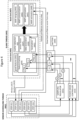
- Figure 4 illustrates functional elements of a SLAM system that performs sensor scheduling operations in accordance with some embodiments of the present disclosure.
- the SLAM system includes a sensor-scheduling-thread functional block 401, a slam-thread functional block 403, a set of sensors S 1 ,S 2 , S n , a battery 409, and a sensor control block having a sampling regulator 421 and a power mode controller 422.
- the sensor-sensor-scheduling-thread functional block 401 is configured to perform operational steps that include: activating (STEP 411) a set of sensors S A ; determining (STEP 412) number of inliers and outliers for each sensor s i among a set of sensors; determining (STEP 413) a confidence score ⁇ i to each sensor s i ; defining (STEP 414) a subset of the sensors S B among the set of sensors S A to remain active based on their confidence score ( S B ⁇ S A ); defining (STEP 415) set of sensors Sc to remain active based on their utilization of hardware resources and their overall confidence score ( S C ⁇ S B ); and regulating (STEP 416) the sampling rate of sensors based on the device's dynamics, e.g., translational speed, rotational speed, etc., and/or the environment's dynamics, e.g., sunrise/sunset timeframe, high contrast shadow occurrence density, etc.
- the device's dynamics e.g
- the slam-thread functional block 403 is configured to perform SLAM operations.
- the slam-thread functional block 403 includes front-end operations 405 and back-end operations 407.
- Front-end operations 405 may include good features determination functions 431, feature tracking functions 433, outlier detection functions 435, sensor fusion functions 437, data association functions 439, and localization functions 441.
- the back-end operations 407 may include map merging functions 443, map summarization functions 445, map optimization functions 447, and map estimation functions 449.
- the sensor control functional block activates and deactivates the set of sensors S 1 ,S 2 , and S n through operations performed by a sampling regulator 421 that controls sensors' sampling rate and/or through operations performed by a power mode controller 422 that controls power consumption by the sensors.
- the terms “comprise”, “comprising”, “comprises”, “include”, “including”, “includes”, “have”, “has”, “having”, or variants thereof are open-ended, and include one or more stated features, integers, elements, steps, components or functions but does not preclude the presence or addition of one or more other features, integers, elements, steps, components, functions or groups thereof.
- the common abbreviation “e.g.”, which derives from the Latin phrase “exempli gratia” may be used to introduce or specify a general example or examples of a previously mentioned item, and is not intended to be limiting of such item.
- the common abbreviation “i.e.”, which derives from the Latin phrase “id est,” may be used to specify a particular item from a more general recitation.
- Example embodiments are described herein with reference to block diagrams and/or flowchart illustrations of computer-implemented methods, apparatus (systems and/or devices) and/or computer program products. It is understood that a block of the block diagrams and/or flowchart illustrations, and combinations of blocks in the block diagrams and/or flowchart illustrations, can be implemented by computer program instructions that are performed by one or more computer circuits.
- These computer program instructions may be provided to a processor circuit of a general purpose computer circuit, special purpose computer circuit, and/or other programmable data processing circuit to produce a machine, such that the instructions, which execute via the processor of the computer and/or other programmable data processing apparatus, transform and control transistors, values stored in memory locations, and other hardware components within such circuitry to implement the functions/acts specified in the block diagrams and/or flowchart block or blocks, and thereby create means (functionality) and/or structure for implementing the functions/acts specified in the block diagrams and/or flowchart block(s).
Landscapes
- Engineering & Computer Science (AREA)
- Theoretical Computer Science (AREA)
- Physics & Mathematics (AREA)
- Computer Hardware Design (AREA)
- General Physics & Mathematics (AREA)
- General Engineering & Computer Science (AREA)
- Human Computer Interaction (AREA)
- Signal Processing (AREA)
- Multimedia (AREA)
- Computer Vision & Pattern Recognition (AREA)
- Computing Systems (AREA)
- Software Systems (AREA)
- Computer Networks & Wireless Communication (AREA)
- Electromagnetism (AREA)
- Radar, Positioning & Navigation (AREA)
- Remote Sensing (AREA)
- Control Of Position, Course, Altitude, Or Attitude Of Moving Bodies (AREA)
- Navigation (AREA)
- Studio Devices (AREA)
- Image Analysis (AREA)
- Position Fixing By Use Of Radio Waves (AREA)
- Measurement Of Velocity Or Position Using Acoustic Or Ultrasonic Waves (AREA)
- Mobile Radio Communication Systems (AREA)
Claims (21)
- Verfahren, bei dem eine mobile Vorrichtung eine Lokalisierung der mobilen Vorrichtung unter Verwendung einer Gruppe von Sensoren durchführt, die mit der mobilen Vorrichtung transportiert werden,
wobei das Verfahren Folgendes umfasst:Bestimmen (600) eines Vertrauenswerts (λi) für jeden der Sensoren (Si) in der Gruppe von Sensoren;Definieren (602) einer Untergruppe der Sensoren in der Gruppe von Sensoren, die aktiv zu bleiben haben, basierend auf ihren jeweiligen Vertrauenswerten, die einen definierten Schwellenwert erfüllen; undDeaktivieren (604) der Sensoren innerhalb der Gruppe von Sensoren, die nicht zu der Untergruppe gehören, wobei die Deaktivierung Steuern des Stromverbrauchs durch deaktivierte Sensoren umfasst,dadurch gekennzeichnet, dass das Definieren (602) der Untergruppe der Sensoren in der Gruppe von Sensoren (301, 303, 305), die aktiv zu bleiben haben, ferner auf einer Kombination ihrer jeweiligen Vertrauenswerte und einem Ähnlichkeitsgrad bei den Betriebseigenschaften der Sensoren basiert. - Verfahren nach Anspruch 1, wobei die Untergruppe der Sensoren derart definiert ist (602), dass ein Einschließen von Sensoren, deren Ähnlichkeitsgrad im Betrieb einen Schwellenwert überschreitet, bestraft wird.
- Verfahren nach einem der Ansprüche 1 oder 2, wobei der definierte Schwellenwert eine Gruppe von Schwellenwerten umfasst, jeder der Schwellenwerte in der Gruppe mit einem anderen der Sensoren in der Gruppe verknüpft ist, wobei der Schwellenwert für einen der Sensoren in der Gruppe basierend auf einem Vergleich einer vertrauenswürdigen aktuellen Lage der Vorrichtung mit einer Lage, die von einer Lokalisierungsleistung unter Verwendung von Daten von dem Sensor ausgegeben wird, bestimmt wird.
- Mobile Vorrichtung (300), die dazu konfiguriert ist, eine Lokalisierung der mobilen Vorrichtung unter Verwendung einer Gruppe von Sensoren (301, 303, 305), die mit der mobilen Vorrichtung transportierbar sind, durchzuführen, wobei die mobile Vorrichtung (300) Folgendes umfasst:einen Prozessor (309), der mit dem Satz von Sensoren (301, 303, 305) wirkverbunden ist;einen Speicher (306), der Programmcode speichert, der durch den Prozessor (309) ausgeführt wird, um Vorgänge für Folgendes durchzuführen:Bestimmen eines Vertrauenswerts (λi) für jeden der Sensoren (Si) in der Gruppe von Sensoren;Definieren einer Untergruppe der Sensoren in der Gruppe von Sensoren (301, 303, 305), die aktiv zu bleiben haben, basierend auf ihren jeweiligen Vertrauenswerten, die einen definierten Schwellenwert erfüllen; undDeaktivieren der Sensoren innerhalb der Gruppe von Sensoren (301, 303, 305), die nicht zu der Untergruppe gehören,wobei die Deaktivierung Steuern des Stromverbrauchs durch deaktivierte Sensoren umfasst,
dadurch gekennzeichnet, dass das Definieren der Untergruppe der Sensoren in der Gruppe von Sensoren (301, 303, 305), die aktiv zu bleiben haben, ferner auf einer Kombination ihrer jeweiligen Vertrauenswerte und einem Ähnlichkeitsgrad bei den Betriebseigenschaften der Sensoren basiert. - Vorrichtung (300) nach Anspruch 4, wobei der Prozessor durch den Programmcode ferner dazu konfiguriert ist, einzelne der Sensoren innerhalb der Untergruppe von Sensoren (301, 303, 305), basierend auf einer Bestimmung, ob ihre jeweilige Nutzung von Hardware-Ressourcen eine definierte Regel erfüllt, selektiv zu deaktivieren.
- Vorrichtung (300) nach Anspruch 5, wobei die Hardware-Ressourcen mindestens eines aus Stromverbrauch, Prozessorauslastung, Speicherauslastung und Netzwerkkommunikationsauslastung umfassen.
- Vorrichtung (300) nach einem der Ansprüche 4 bis 6, wobei der Prozessor durch den Programmcode ferner dazu konfiguriert ist, eine Abtastrate der Sensoren in der Untergruppe, die aktiv sind, basierend auf der Geschwindigkeit der Vorrichtung (300) zu regulieren.
- Vorrichtung (300) nach einem der Ansprüche 4 bis 7, wobei der Vertrauenswert für einen der Sensoren basierend auf einem Verhältnis einer Anzahl von Inlier-Merkmalen zu einer Gesamtanzahl von Inlier- und Outlier-Merkmalen, das durch den Sensor erkannt wird, bestimmt wird.
- Vorrichtung (300) nach Anspruch 8, wobei jedes der Inlier-Merkmale Eigenschaften aufweist, die mit einem definierten Modell konsistent sind, und jedes der Outlier-Merkmale Eigenschaften aufweist, die mit dem definierten Modell nicht konsistent sind.
- Vorrichtung (300) nach einem der Ansprüche 4 bis 9, wobei der Vertrauenswert für einen der Sensoren basierend auf einem Schwingungsausmaß bestimmt wird, dessen Auftreten zwischen Positionen von Merkmalen innerhalb von Sensordaten, die in aufeinanderfolgenden Abtastbildern erhalten werden, bestimmt wird.
- Vorrichtung (300) nach Anspruch 10, wobei die Positionen von Merkmalen innerhalb der Sensordaten Schlüsselpunkte innerhalb von Bildern von einem Kamerasensor sind.
- Vorrichtung (300) nach einem der Ansprüche 4 bis 11, wobei der Vertrauenswert für einen der Sensoren basierend auf einem Signal-Rausch-Verhältnis (SNR) des Sensors im Vergleich zu einem definierten Schwellenwert bestimmt wird.
- Vorrichtung (300) nach einem der Ansprüche 4 bis 12, wobei der Vertrauenswert für einen der Sensoren basierend auf Bestimmen einer Lokalisierung des Sensors relativ zu einer Karte einer Umgebung, die durch eine Datenstruktur, die Merkmale enthält, die zuvor durch einen oder mehrere Sensoren erfasst wurden, definiert ist, und Bestimmen des Vertrauenswerts für den einen der Sensoren basierend darauf, ob der Sensor derzeit die Merkmale erfasst, die in der Datenstruktur, welche die Karte definiert, enthalten sind, bestimmt wird (600).
- Vorrichtung (300) nach einem der Ansprüche 4 bis 13, wobei der Vertrauenswert für einen der Sensoren basierend auf Bestimmen einer Lokalisierung des Sensors relativ zu einer Karte einer Umgebung, die durch eine Datenstruktur, die Positionen von Merkmalen enthält, definiert wird, und Bestimmen des Vertrauenswerts für den einen der Sensoren basierend auf einem Vergleich der Stellen, wo der Sensor die Lagen der Merkmale erkennt, mit den Stellen, wo die Datenstruktur die Lagen der Merkmale erkennt, bestimmt wird.
- Vorrichtung (300) nach einem der Ansprüche 4 bis 14, wobei der Vertrauenswert für einen der Sensoren basierend auf einer Lokalisierung des Sensors an Orten innerhalb einer Karte einer Umgebung, die durch eine Datenstruktur, die eine Leistung von Sensoren an den Orten identifiziert, definiert wird, Abrufen aus der Datenstruktur einer Leistung für den Sensor basierend auf der Lokalisierung an den Orten und Bestimmen des Vertrauenswerts basierend auf der abgerufenen Leistung bestimmt wird.
- Vorrichtung (300) nach einem der Ansprüche 13 bis 15, wobei der Vertrauenswert für den einen der Sensoren basierend auf Zugreifen auf die Datenstruktur der Karte, die in einem Netzwerk-Daten-Repository gespeichert ist, bestimmt wird.
- Vorrichtung (300) nach einem der Ansprüche 4 bis 16, wobei die Deaktivierung eines Sensors eines von Auslösen eines Übergangs des Sensors in einen niedrigeren Leistungszustand und Auslösen einer Abschaltung des Sensors umfasst.
- Vorrichtung (300) nach einem der Ansprüche 4 bis 17, wobei die Deaktivierung eines Sensors Einstellen einer Datenabtastrate des Sensors auf eines aus einer reduzierten Abtastrate und Null umfasst.
- Vorrichtung (300) nach einem der Ansprüche 4 bis 18, wobei die Untergruppe der Sensoren derart definiert ist, dass ein Einschließen von Sensoren, deren Ähnlichkeitsgrad im Betrieb einen Schwellenwert überschreitet, bestraft wird.
- Vorrichtung (300) nach einem der Ansprüche 4 bis 19, ferner umfassend:einen Transceiver (307),wobei der Prozessor durch den Programmcode ferner zu Folgendem konfiguriert ist:Kommunizieren, über den Transceiver, mit einer in der Nähe angeordneten Vorrichtung (310),wobei der Vertrauenswert für einen der Sensoren basierend auf Erhalten, von der in der Nähe angeordneten Vorrichtung, einer Auflistung von Sensoren, die gegenwärtig zur Verwendung durch die in der Nähe angeordnete Vorrichtung aktiv sind, bestimmt wird.
- Vorrichtung (300) nach einem der Ansprüche 4 bis 20, wobei der definierte Schwellenwert einen Satz von Schwellenwerten umfasst, wobei jeder der Schwellenwerte in dem Satz mit einem anderen der Sensoren in dem Satz verknüpft ist, wobei der Prozessor durch den Programmcode ferner dazu konfiguriert ist, den Schwellenwert für einen der Sensoren in der Gruppe basierend auf einem Vergleich einer vertrauenswürdigen aktuellen Lage der Vorrichtung mit einer Lage, die von einer Lokalisierungsleistung unter Verwendung von Daten von dem Sensor ausgegeben wird, bestimmt wird.
Applications Claiming Priority (1)
| Application Number | Priority Date | Filing Date | Title |
|---|---|---|---|
| PCT/EP2019/085723 WO2021121564A1 (en) | 2019-12-17 | 2019-12-17 | Controlling sensor activation and deactivation for energy efficient localization |
Publications (2)
| Publication Number | Publication Date |
|---|---|
| EP4078520A1 EP4078520A1 (de) | 2022-10-26 |
| EP4078520B1 true EP4078520B1 (de) | 2025-02-19 |
Family
ID=69104393
Family Applications (1)
| Application Number | Title | Priority Date | Filing Date |
|---|---|---|---|
| EP19831666.3A Active EP4078520B1 (de) | 2019-12-17 | 2019-12-17 | Steuerung der sensoraktivierung und -deaktivierung zur energieeffizienten lokalisierung |
Country Status (6)
| Country | Link |
|---|---|
| US (1) | US20230033951A1 (de) |
| EP (1) | EP4078520B1 (de) |
| JP (1) | JP7474849B2 (de) |
| CN (1) | CN114830178A (de) |
| WO (1) | WO2021121564A1 (de) |
| ZA (1) | ZA202207482B (de) |
Families Citing this family (8)
| Publication number | Priority date | Publication date | Assignee | Title |
|---|---|---|---|---|
| EP4100916B1 (de) * | 2020-02-07 | 2025-04-09 | Telefonaktiebolaget Lm Ericsson (Publ) | Aktivierung einer monokularen kamera zur lokalisierung auf basis von daten aus einem tiefensensor |
| US12256293B2 (en) * | 2020-03-30 | 2025-03-18 | EMC IP Holding Company LLC | Increasing device data confidence and operation via temporal and spatial analytics |
| US20220144304A1 (en) * | 2020-11-09 | 2022-05-12 | Nvidia Corporation | Safety decomposition for path determination in autonomous systems |
| US20230161403A1 (en) * | 2021-11-22 | 2023-05-25 | Htc Corporation | Method for managing tracking sensors, tracking device, and computer readable storage medium |
| WO2023204740A1 (en) * | 2022-04-19 | 2023-10-26 | Telefonaktiebolaget Lm Ericsson (Publ) | Selective localization and mapping of a partially known environment |
| US20230383497A1 (en) * | 2022-05-26 | 2023-11-30 | Deere & Company | Work machine with an adaptive control system and method for grade control |
| JP7831407B2 (ja) * | 2023-06-07 | 2026-03-17 | トヨタ自動車株式会社 | 自動運転システム |
| CN120380924A (zh) * | 2024-01-26 | 2025-07-29 | 南京泉峰科技有限公司 | 自移动割草机和自移动割草机的建边方法 |
Family Cites Families (12)
| Publication number | Priority date | Publication date | Assignee | Title |
|---|---|---|---|---|
| US8754789B2 (en) * | 2009-11-24 | 2014-06-17 | Mitel Networks Corporation | Power management system and method for mobile applications using location based services |
| US8472973B2 (en) * | 2010-04-23 | 2013-06-25 | Microsoft Corporation | Adaptive energy-efficient location determination |
| US9389690B2 (en) * | 2012-03-01 | 2016-07-12 | Qualcomm Incorporated | Gesture detection based on information from multiple types of sensors |
| US20140351560A1 (en) * | 2013-05-24 | 2014-11-27 | Motorola Mobility Llc | Low Power Management of Multiple Sensor Integrated Chip Architecture |
| US20140240469A1 (en) * | 2013-02-28 | 2014-08-28 | Motorola Mobility Llc | Electronic Device with Multiview Image Capture and Depth Sensing |
| KR102303952B1 (ko) * | 2015-01-05 | 2021-09-24 | 나이키 이노베이트 씨.브이. | 다수의 디바이스들로부터의 데이터를 이용한 에너지 소비량 계산 |
| JP2016197083A (ja) * | 2015-04-06 | 2016-11-24 | ソニー株式会社 | 制御装置および方法、並びにプログラム |
| US10890600B2 (en) * | 2016-05-18 | 2021-01-12 | Google Llc | Real-time visual-inertial motion tracking fault detection |
| US10423212B2 (en) * | 2017-06-02 | 2019-09-24 | Apple Inc. | Techniques for adjusting computing device sleep states using onboard sensors and learned user behaviors |
| US11202006B2 (en) * | 2018-05-18 | 2021-12-14 | Samsung Electronics Co., Ltd. | CMOS-assisted inside-out dynamic vision sensor tracking for low power mobile platforms |
| CN109556615B (zh) * | 2018-10-10 | 2022-10-04 | 吉林大学 | 基于自动驾驶的多传感器融合认知的驾驶地图生成方法 |
| US11281217B2 (en) * | 2019-06-25 | 2022-03-22 | Ford Global Technologies, Llc | Enhanced vehicle operation |
-
2019
- 2019-12-17 JP JP2022531042A patent/JP7474849B2/ja active Active
- 2019-12-17 EP EP19831666.3A patent/EP4078520B1/de active Active
- 2019-12-17 CN CN201980103077.2A patent/CN114830178A/zh active Pending
- 2019-12-17 US US17/786,097 patent/US20230033951A1/en active Pending
- 2019-12-17 WO PCT/EP2019/085723 patent/WO2021121564A1/en not_active Ceased
-
2022
- 2022-07-06 ZA ZA2022/07482A patent/ZA202207482B/en unknown
Also Published As
| Publication number | Publication date |
|---|---|
| US20230033951A1 (en) | 2023-02-02 |
| CN114830178A (zh) | 2022-07-29 |
| JP2023505962A (ja) | 2023-02-14 |
| WO2021121564A1 (en) | 2021-06-24 |
| ZA202207482B (en) | 2025-12-17 |
| EP4078520A1 (de) | 2022-10-26 |
| JP7474849B2 (ja) | 2024-04-25 |
Similar Documents
| Publication | Publication Date | Title |
|---|---|---|
| EP4078520B1 (de) | Steuerung der sensoraktivierung und -deaktivierung zur energieeffizienten lokalisierung | |
| Wang et al. | Development of UAV-based target tracking and recognition systems | |
| Hausler et al. | Multi-process fusion: Visual place recognition using multiple image processing methods | |
| US10671068B1 (en) | Shared sensor data across sensor processing pipelines | |
| JP2022536030A (ja) | ビデオ分析アプリケーションにおける相関フィルタを使用した複数物体追跡 | |
| US11741720B2 (en) | System and method for tracking objects using using expanded bounding box factors | |
| US10948986B2 (en) | System for performing eye detection and/or tracking | |
| KR20210066119A (ko) | 무인 항공기 영상 내 실시간 객체 검출 방법 및 장치 | |
| Ait Abdelali et al. | An adaptive object tracking using Kalman filter and probability product kernel | |
| CN118154639A (zh) | 用于自主系统及应用的对象跟踪管理 | |
| Rostum et al. | A review of using visual odometery methods in autonomous UAV Navigation in GPS-Denied Environment | |
| US10521964B1 (en) | Switching among disparate simultaneous localization and mapping (SLAM) methods in virtual, augmented, and mixed reality (xR) applications | |
| Le et al. | Human detection and tracking for autonomous human-following quadcopter | |
| US12607464B2 (en) | Localization using sensors that are transportable with a device | |
| US10074187B2 (en) | Image recognition system and semiconductor integrated circuit | |
| CN109325962B (zh) | 信息处理方法、装置、设备以及计算机可读存储介质 | |
| Chi et al. | Dynamic small target detection and tracking based on hierarchical network and adaptive input image stream | |
| Li et al. | Low-cost environment-adaptive SLAM for bed-chair robots in complex indoor scenarios | |
| Wu et al. | Research on Binocular Vision Pose Tracking and Detection Algorithm Based on Deep Learning | |
| WO2025065724A1 (en) | Decoupled queries for end-to-end 3d tracking using tranformer neural networks | |
| US20240169183A1 (en) | Method for performing a perception task of an electronic device or a vehicle using a plurality of neural networks | |
| WO2024119469A1 (en) | Apparatus and methods for clustering and matching feature descriptors | |
| Coelho et al. | Bioinspired SLAM Approach for Unmanned Surface Vehicle | |
| Zhong et al. | FWFR-SLAM: A Robust Monocular SLAM System for Flapping-Wing Flying Robots | |
| Agaoglu et al. | Fast maritime horizon line tracking with on-off region-of-interest control |
Legal Events
| Date | Code | Title | Description |
|---|---|---|---|
| STAA | Information on the status of an ep patent application or granted ep patent |
Free format text: STATUS: UNKNOWN |
|
| STAA | Information on the status of an ep patent application or granted ep patent |
Free format text: STATUS: THE INTERNATIONAL PUBLICATION HAS BEEN MADE |
|
| PUAI | Public reference made under article 153(3) epc to a published international application that has entered the european phase |
Free format text: ORIGINAL CODE: 0009012 |
|
| STAA | Information on the status of an ep patent application or granted ep patent |
Free format text: STATUS: REQUEST FOR EXAMINATION WAS MADE |
|
| 17P | Request for examination filed |
Effective date: 20220622 |
|
| AK | Designated contracting states |
Kind code of ref document: A1 Designated state(s): AL AT BE BG CH CY CZ DE DK EE ES FI FR GB GR HR HU IE IS IT LI LT LU LV MC MK MT NL NO PL PT RO RS SE SI SK SM TR |
|
| DAV | Request for validation of the european patent (deleted) | ||
| DAX | Request for extension of the european patent (deleted) | ||
| GRAP | Despatch of communication of intention to grant a patent |
Free format text: ORIGINAL CODE: EPIDOSNIGR1 |
|
| STAA | Information on the status of an ep patent application or granted ep patent |
Free format text: STATUS: GRANT OF PATENT IS INTENDED |
|
| RIC1 | Information provided on ipc code assigned before grant |
Ipc: H04N 23/65 20230101ALI20241125BHEP Ipc: H04N 23/617 20230101ALI20241125BHEP Ipc: G06F 1/3287 20190101ALI20241125BHEP Ipc: G06F 1/16 20060101ALI20241125BHEP Ipc: G01S 17/931 20200101ALI20241125BHEP Ipc: G06F 1/3234 20190101ALI20241125BHEP Ipc: G06F 1/3215 20190101ALI20241125BHEP Ipc: G06T 7/73 20170101AFI20241125BHEP |
|
| INTG | Intention to grant announced |
Effective date: 20241210 |
|
| GRAS | Grant fee paid |
Free format text: ORIGINAL CODE: EPIDOSNIGR3 |
|
| GRAA | (expected) grant |
Free format text: ORIGINAL CODE: 0009210 |
|
| STAA | Information on the status of an ep patent application or granted ep patent |
Free format text: STATUS: THE PATENT HAS BEEN GRANTED |
|
| AK | Designated contracting states |
Kind code of ref document: B1 Designated state(s): AL AT BE BG CH CY CZ DE DK EE ES FI FR GB GR HR HU IE IS IT LI LT LU LV MC MK MT NL NO PL PT RO RS SE SI SK SM TR |
|
| REG | Reference to a national code |
Ref country code: GB Ref legal event code: FG4D |
|
| REG | Reference to a national code |
Ref country code: CH Ref legal event code: EP |
|
| REG | Reference to a national code |
Ref country code: DE Ref legal event code: R096 Ref document number: 602019066260 Country of ref document: DE |
|
| REG | Reference to a national code |
Ref country code: IE Ref legal event code: FG4D |
|
| REG | Reference to a national code |
Ref country code: NL Ref legal event code: MP Effective date: 20250219 |
|
| PG25 | Lapsed in a contracting state [announced via postgrant information from national office to epo] |
Ref country code: RS Free format text: LAPSE BECAUSE OF FAILURE TO SUBMIT A TRANSLATION OF THE DESCRIPTION OR TO PAY THE FEE WITHIN THE PRESCRIBED TIME-LIMIT Effective date: 20250519 |
|
| PG25 | Lapsed in a contracting state [announced via postgrant information from national office to epo] |
Ref country code: FI Free format text: LAPSE BECAUSE OF FAILURE TO SUBMIT A TRANSLATION OF THE DESCRIPTION OR TO PAY THE FEE WITHIN THE PRESCRIBED TIME-LIMIT Effective date: 20250219 |
|
| PG25 | Lapsed in a contracting state [announced via postgrant information from national office to epo] |
Ref country code: PL Free format text: LAPSE BECAUSE OF FAILURE TO SUBMIT A TRANSLATION OF THE DESCRIPTION OR TO PAY THE FEE WITHIN THE PRESCRIBED TIME-LIMIT Effective date: 20250219 |
|
| PG25 | Lapsed in a contracting state [announced via postgrant information from national office to epo] |
Ref country code: ES Free format text: LAPSE BECAUSE OF FAILURE TO SUBMIT A TRANSLATION OF THE DESCRIPTION OR TO PAY THE FEE WITHIN THE PRESCRIBED TIME-LIMIT Effective date: 20250219 |
|
| REG | Reference to a national code |
Ref country code: LT Ref legal event code: MG9D |
|
| PG25 | Lapsed in a contracting state [announced via postgrant information from national office to epo] |
Ref country code: NO Free format text: LAPSE BECAUSE OF FAILURE TO SUBMIT A TRANSLATION OF THE DESCRIPTION OR TO PAY THE FEE WITHIN THE PRESCRIBED TIME-LIMIT Effective date: 20250519 Ref country code: IS Free format text: LAPSE BECAUSE OF FAILURE TO SUBMIT A TRANSLATION OF THE DESCRIPTION OR TO PAY THE FEE WITHIN THE PRESCRIBED TIME-LIMIT Effective date: 20250619 |
|
| PG25 | Lapsed in a contracting state [announced via postgrant information from national office to epo] |
Ref country code: NL Free format text: LAPSE BECAUSE OF FAILURE TO SUBMIT A TRANSLATION OF THE DESCRIPTION OR TO PAY THE FEE WITHIN THE PRESCRIBED TIME-LIMIT Effective date: 20250219 |
|
| PG25 | Lapsed in a contracting state [announced via postgrant information from national office to epo] |
Ref country code: HR Free format text: LAPSE BECAUSE OF FAILURE TO SUBMIT A TRANSLATION OF THE DESCRIPTION OR TO PAY THE FEE WITHIN THE PRESCRIBED TIME-LIMIT Effective date: 20250219 |
|
| PG25 | Lapsed in a contracting state [announced via postgrant information from national office to epo] |
Ref country code: LV Free format text: LAPSE BECAUSE OF FAILURE TO SUBMIT A TRANSLATION OF THE DESCRIPTION OR TO PAY THE FEE WITHIN THE PRESCRIBED TIME-LIMIT Effective date: 20250219 Ref country code: PT Free format text: LAPSE BECAUSE OF FAILURE TO SUBMIT A TRANSLATION OF THE DESCRIPTION OR TO PAY THE FEE WITHIN THE PRESCRIBED TIME-LIMIT Effective date: 20250620 |
|
| PG25 | Lapsed in a contracting state [announced via postgrant information from national office to epo] |
Ref country code: GR Free format text: LAPSE BECAUSE OF FAILURE TO SUBMIT A TRANSLATION OF THE DESCRIPTION OR TO PAY THE FEE WITHIN THE PRESCRIBED TIME-LIMIT Effective date: 20250520 Ref country code: BG Free format text: LAPSE BECAUSE OF FAILURE TO SUBMIT A TRANSLATION OF THE DESCRIPTION OR TO PAY THE FEE WITHIN THE PRESCRIBED TIME-LIMIT Effective date: 20250219 |
|
| REG | Reference to a national code |
Ref country code: AT Ref legal event code: MK05 Ref document number: 1769056 Country of ref document: AT Kind code of ref document: T Effective date: 20250219 |
|
| PG25 | Lapsed in a contracting state [announced via postgrant information from national office to epo] |
Ref country code: SE Free format text: LAPSE BECAUSE OF FAILURE TO SUBMIT A TRANSLATION OF THE DESCRIPTION OR TO PAY THE FEE WITHIN THE PRESCRIBED TIME-LIMIT Effective date: 20250219 |
|
| PG25 | Lapsed in a contracting state [announced via postgrant information from national office to epo] |
Ref country code: SM Free format text: LAPSE BECAUSE OF FAILURE TO SUBMIT A TRANSLATION OF THE DESCRIPTION OR TO PAY THE FEE WITHIN THE PRESCRIBED TIME-LIMIT Effective date: 20250219 |
|
| PG25 | Lapsed in a contracting state [announced via postgrant information from national office to epo] |
Ref country code: DK Free format text: LAPSE BECAUSE OF FAILURE TO SUBMIT A TRANSLATION OF THE DESCRIPTION OR TO PAY THE FEE WITHIN THE PRESCRIBED TIME-LIMIT Effective date: 20250219 |
|
| PG25 | Lapsed in a contracting state [announced via postgrant information from national office to epo] |
Ref country code: IT Free format text: LAPSE BECAUSE OF FAILURE TO SUBMIT A TRANSLATION OF THE DESCRIPTION OR TO PAY THE FEE WITHIN THE PRESCRIBED TIME-LIMIT Effective date: 20250219 |
|
| PG25 | Lapsed in a contracting state [announced via postgrant information from national office to epo] |
Ref country code: AT Free format text: LAPSE BECAUSE OF FAILURE TO SUBMIT A TRANSLATION OF THE DESCRIPTION OR TO PAY THE FEE WITHIN THE PRESCRIBED TIME-LIMIT Effective date: 20250219 |
|
| PG25 | Lapsed in a contracting state [announced via postgrant information from national office to epo] |
Ref country code: CZ Free format text: LAPSE BECAUSE OF FAILURE TO SUBMIT A TRANSLATION OF THE DESCRIPTION OR TO PAY THE FEE WITHIN THE PRESCRIBED TIME-LIMIT Effective date: 20250219 Ref country code: EE Free format text: LAPSE BECAUSE OF FAILURE TO SUBMIT A TRANSLATION OF THE DESCRIPTION OR TO PAY THE FEE WITHIN THE PRESCRIBED TIME-LIMIT Effective date: 20250219 |
|
| PG25 | Lapsed in a contracting state [announced via postgrant information from national office to epo] |
Ref country code: RO Free format text: LAPSE BECAUSE OF FAILURE TO SUBMIT A TRANSLATION OF THE DESCRIPTION OR TO PAY THE FEE WITHIN THE PRESCRIBED TIME-LIMIT Effective date: 20250219 |
|
| PG25 | Lapsed in a contracting state [announced via postgrant information from national office to epo] |
Ref country code: SK Free format text: LAPSE BECAUSE OF FAILURE TO SUBMIT A TRANSLATION OF THE DESCRIPTION OR TO PAY THE FEE WITHIN THE PRESCRIBED TIME-LIMIT Effective date: 20250219 |
|
| REG | Reference to a national code |
Ref country code: DE Ref legal event code: R097 Ref document number: 602019066260 Country of ref document: DE |
|
| PLBE | No opposition filed within time limit |
Free format text: ORIGINAL CODE: 0009261 |
|
| STAA | Information on the status of an ep patent application or granted ep patent |
Free format text: STATUS: NO OPPOSITION FILED WITHIN TIME LIMIT |
|
| PGFP | Annual fee paid to national office [announced via postgrant information from national office to epo] |
Ref country code: GB Payment date: 20251229 Year of fee payment: 7 |
|
| 26N | No opposition filed |
Effective date: 20251120 |
|
| PGFP | Annual fee paid to national office [announced via postgrant information from national office to epo] |
Ref country code: DE Payment date: 20251229 Year of fee payment: 7 |