EP4077904B1 - Kit for replacing a jet filter arranged in an engine fuel pump - Google Patents
Kit for replacing a jet filter arranged in an engine fuel pump Download PDFInfo
- Publication number
- EP4077904B1 EP4077904B1 EP20838386.9A EP20838386A EP4077904B1 EP 4077904 B1 EP4077904 B1 EP 4077904B1 EP 20838386 A EP20838386 A EP 20838386A EP 4077904 B1 EP4077904 B1 EP 4077904B1
- Authority
- EP
- European Patent Office
- Prior art keywords
- cavity
- jet filter
- fuel pump
- centering guide
- extractor
- Prior art date
- Legal status (The legal status is an assumption and is not a legal conclusion. Google has not performed a legal analysis and makes no representation as to the accuracy of the status listed.)
- Active
Links
Images


Classifications
-
- F—MECHANICAL ENGINEERING; LIGHTING; HEATING; WEAPONS; BLASTING
- F02—COMBUSTION ENGINES; HOT-GAS OR COMBUSTION-PRODUCT ENGINE PLANTS
- F02M—SUPPLYING COMBUSTION ENGINES IN GENERAL WITH COMBUSTIBLE MIXTURES OR CONSTITUENTS THEREOF
- F02M37/00—Apparatus or systems for feeding liquid fuel from storage containers to carburettors or fuel-injection apparatus; Arrangements for purifying liquid fuel specially adapted for, or arranged on, internal-combustion engines
- F02M37/22—Arrangements for purifying liquid fuel specially adapted for, or arranged on, internal-combustion engines, e.g. arrangements in the feeding system
- F02M37/32—Arrangements for purifying liquid fuel specially adapted for, or arranged on, internal-combustion engines, e.g. arrangements in the feeding system characterised by filters or filter arrangements
- F02M37/42—Installation or removal of filters
-
- B—PERFORMING OPERATIONS; TRANSPORTING
- B25—HAND TOOLS; PORTABLE POWER-DRIVEN TOOLS; MANIPULATORS
- B25B—TOOLS OR BENCH DEVICES NOT OTHERWISE PROVIDED FOR, FOR FASTENING, CONNECTING, DISENGAGING, OR HOLDING
- B25B27/00—Hand tools, specially adapted for fitting together or separating parts or objects whether or not involving some deformation, not otherwise provided for
- B25B27/0035—Hand tools, specially adapted for fitting together or separating parts or objects whether or not involving some deformation, not otherwise provided for for motor-vehicles
- B25B27/0042—Tools for removing or replacing filters or for draining oil; Tools for setting or loosening closure means for radiators, batteries, or the like
-
- F—MECHANICAL ENGINEERING; LIGHTING; HEATING; WEAPONS; BLASTING
- F02—COMBUSTION ENGINES; HOT-GAS OR COMBUSTION-PRODUCT ENGINE PLANTS
- F02M—SUPPLYING COMBUSTION ENGINES IN GENERAL WITH COMBUSTIBLE MIXTURES OR CONSTITUENTS THEREOF
- F02M37/00—Apparatus or systems for feeding liquid fuel from storage containers to carburettors or fuel-injection apparatus; Arrangements for purifying liquid fuel specially adapted for, or arranged on, internal-combustion engines
- F02M37/02—Feeding by means of suction apparatus, e.g. by air flow through carburettors
- F02M37/025—Feeding by means of a liquid fuel-driven jet pump
-
- F—MECHANICAL ENGINEERING; LIGHTING; HEATING; WEAPONS; BLASTING
- F02—COMBUSTION ENGINES; HOT-GAS OR COMBUSTION-PRODUCT ENGINE PLANTS
- F02M—SUPPLYING COMBUSTION ENGINES IN GENERAL WITH COMBUSTIBLE MIXTURES OR CONSTITUENTS THEREOF
- F02M37/00—Apparatus or systems for feeding liquid fuel from storage containers to carburettors or fuel-injection apparatus; Arrangements for purifying liquid fuel specially adapted for, or arranged on, internal-combustion engines
- F02M37/22—Arrangements for purifying liquid fuel specially adapted for, or arranged on, internal-combustion engines, e.g. arrangements in the feeding system
- F02M37/32—Arrangements for purifying liquid fuel specially adapted for, or arranged on, internal-combustion engines, e.g. arrangements in the feeding system characterised by filters or filter arrangements
- F02M37/44—Filters structurally associated with pumps
-
- F—MECHANICAL ENGINEERING; LIGHTING; HEATING; WEAPONS; BLASTING
- F02—COMBUSTION ENGINES; HOT-GAS OR COMBUSTION-PRODUCT ENGINE PLANTS
- F02M—SUPPLYING COMBUSTION ENGINES IN GENERAL WITH COMBUSTIBLE MIXTURES OR CONSTITUENTS THEREOF
- F02M65/00—Testing fuel-injection apparatus, e.g. testing injection timing ; Cleaning of fuel-injection apparatus
- F02M65/007—Cleaning
Definitions
- the present invention relates to a kit for replacing a JET filter arranged in an engine fuel pump, as well as to a method for extracting and a method for fitting the JET filter in an engine fuel pump.
- a fuel pump actuator is provided in order to regulate the quantity of fuel flowing from the fuel pump to fuel injectors.
- Fuel flowing through the fuel pump actuator brings impurities coming from different elements of the motor vehicle engine that are crossed by the fuel before arriving at the fuel pump actuator. These elements are for example the fuel tank, the fuel heater or other parts of the fuel pump. Impurities can also appear because of a low quality fuel.
- JET filter a filter, called JET filter, is provided in the fuel pump in a position close to the actuator. Thus, impurities are accumulated in the JET filter.
- the JET filter is placed in a position that is hardly accessible by using conventional tools. So, its removal from the fuel pump is difficult. In addition, by using conventional tools, a risk of introducing metallic particles inside the injection system exits.
- kits for replacing a JET filter arranged in an engine fuel pump the JET filter being placed on a lateral wall of a fuel pump cavity.
- the kit comprising an extractor for extracting said JET filter, a pushing rod for fitting a JET filter in the engine fuel pump, and a centering guide shaped to cooperate with the extractor and the pushing rod.
- the centering guide is configured to be partially positioned in the cavity of the fuel pump.
- the centering guide comprises a main body including a cavity, wherein the cavity is shaped such that the JET filter can be extracted from the engine fuel pump by the extractor or can be pushed to the engine fuel pump by the pushing rod.
- the JET filter is reached by the extractor when the extractor and the centering guide cooperate. Hence, the JET filter can be removed from the fuel pump.
- the extractor comprising a handle and a bar, wherein a first end of said bar comprises a threaded surface to engage the JET filter.
- the bar is shaped to cooperate with the centering guide, the extractor being provided with a nut surrounding a portion of said bar.
- the pushing rod comprising a handle and a bar, wherein a first end of said bar is shaped to push the JET filter to a final position in the engine fuel pump.
- the bar is shaped to cooperate with the centering guide.
- the main body comprises a cylindrically shaped portion.
- the main body comprises a trapezoidal prism shaped portion.
- the trapezoidal prism shaped portion comprises an entry orifice of the cavity of the main body, and the cylindrically shaped portion comprises an exit orifice of said cavity.
- the entry orifice is arranged on a face of the trapezoidal prism shaped portion, the face being substantially perpendicular to a longitudinal axis of the cavity.
- the longitudinal axis of the cavity is tilted in relation to a longitudinal axis of the cylindrically shaped portion.
- the invention further extends to a method for extracting the JET filter arranged in the engine fuel pump by means of the present kit, the method comprising the steps of:
- the invention yet further extends to a method for fitting the JET filter in the engine fuel pump by means of the present kit, the method comprising the steps of:
- an engine fuel pump 1 comprises a cavity 2, and a JET filter 3 placed on a lateral wall of the cavity 2.
- the cavity 2 has advantageously a substantially cylindrical shape extending along an axial direction A.
- the axial direction A corresponds to longitudinal axis of the cavity (2).
- the cavity 2 is in particular shaped to install therein a fuel pump actuator.
- the fuel pump actuator is further screwed to a first hole 4 and to a second hole 5 arranged on a face 6 of the engine fuel pump 1, the face 6 being substantially perpendicular to the axial direction A of the cavity 2.
- the first hole 4 and the second hole 5 are positioned next to the cavity 2, on diagonally opposite positions between them.
- the JET filter 3 advantageously has a substantially cylindrical shape.
- a base of the JET filter 3 comprises a grid allowing retaining impurities.
- a lateral wall of the JET filter 3 comprises a threaded surface.
- the present invention relates to a JET filter extractor 10 and a centering guide 32 shaped to allow the extraction of the JET filter 3 from the fuel pump 1 when the extractor 10 and the centering guide 32 are used in combination.
- the present invention further relates to a JET filter pushing rod 20 shaped to allow the fitting of the JET filter 3 in the fuel pump 1 when used in combination with the centering guide 32.
- FIG. 2 shows a JET filter extraction assembly used in order to apply a method for extracting the JET filter 3 from the fuel pump 1.
- the JET filter extraction assembly includes the extractor 10 and the centering guide 32.
- the centering guide 32 is partially positioned in the cavity 2 of the fuel pump 1, while the extractor 10 goes through the centering guide 32.
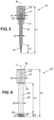
- FIG. 3 shows a JET filter insertion assembly used in order to apply a method for fitting the JET filter 3 in the fuel pump 1.
- the JET filter insertion assembly includes the pushing rod 20 and the centering guide 32. As in the JET filter extraction assembly, the centering guide 32 is partially positioned in the cavity 2 of the fuel pump 1, while the pushing rod 20 goes through the centering guide 32.
- the extractor 10 is shaped to engage the JET filter 3, so that the JET filter 3 can be extracted from the fuel pump 1.
- the extractor 10 comprises a handle 11, a bar 12 and a nut 13.
- the handle 11 and the bar 12 extend along an axial direction B of the extractor 10.
- a length L1 of the extractor 10 is preferably comprised between 80 mm and 90 mm, preferably between 83 mm and 87 mm.
- the handle 11 comprises a rough portion 14 placed between two substantially smooth portions 15.
- the handle 11 is made of a metallic material, preferably of unalloyed steel.
- the handle 11 is made of a C35 unalloyed steel.
- the handle 11 has a cylindrical shape.
- a diameter d1 of the handle 11 is comprised in a range between 14 mm and 16 mm, preferably between 14.8 mm and 15.2 mm.
- the bar 12 comprises a first end 16, a second end 17 and a central part 18, the central part 18 being positioned between the first and the second ends 16, 17.
- the first end 16 comprises a threaded surface.
- a surface of the second end 17 and a surface of the central part 18 are substantially smooth.
- the second end 17 and the central part 18 have a substantially circular section, a diameter d3 of the central part 18 being larger than a diameter d2 of the second end 17.
- the diameter d3 is comprised in a range from 5 mm to 6 mm, preferably from 5.3 to 5.8 mm.
- the bar 12 is made of a metallic material, preferably of unalloyed steel.
- the bar 12 is made of C45 unalloyed steel.
- the handle 11 and the bar 12 are firmly attached between them.
- the second end 17 of the bar 12 is inserted inside a cavity 19 of the handle 11, the cavity 19 extending along the axial direction B of the extractor 10.
- a screw connection is established between the handle 11 and the second end 17 of the bar 12.
- the connection between the handle 11 and the second end 17 of the bar 12 is established by adhesive means.
- the adhesive means are, for example, a layer of glue between the surface of the second end 17 and a surface of the cavity 19.
- the attachment can also be established by using both the screw connection and the adhesive means.
- the cavity 19 has a circular section having a diameter substantially equal to the diameter d2 of the second end 17.
- the nut 13 is coupled to the central part 18 of the bar 12.
- the nut surrounds a portion of the central part 18, said portion being close to the handle 11.
- the nut 13 comprises an external surface and an internal surface.
- the external surface is substantially hexagonal, while the internal surface is substantially circular.
- the internal surface of the nut 13 is in contact with the surface of the central part 18, a diameter of the internal surface of the nut 13 being substantially equal to a diameter of the central part 18.
- the nut 13 is a M5 type nut.
- a length L2 of the first end 16 of the bar is comprised in a range between 14 mm and 17 mm, preferably between 15 mm and 16 mm.
- the threaded surface of the first end 16 of the bar 12 is shaped to cooperate with the JET filter.
- said threaded surface is adapted to cooperate with the threaded surface of the lateral wall of the JET filter.
- the JET filter can be hooked in the bar 12 by screwing the bar 14 around the B-axis.
- FIG. 6 shows the JET filter pushing rod 20.
- the pushing rod 20 is used to push the JET filter 3 inside the cavity of the centering guide 32, so that the JET filter 3 can be fitted in the fuel pump 1.
- the pushing rod 20 comprises a handle 21 and a bar 22 extending along an axial direction C of the pushing rod 20.
- the handle 21 and the bar 22 constitute a single piece having a length L3 comprised in a range from 55 mm to 65 mm, preferably from 58 mm to 62 mm.
- the pushing rod 20 is made of a metallic material, preferably of unalloyed steel.
- the handle 21 and the bar 22 are made of a C35 unalloyed steel.
- the handle 21 comprises a rough portion 23 placed between two substantially smooth portions 24.
- the handle 21 has a cylindrical shape.
- a diameter d4 of the handle 21 is comprised in a range between 9 mm and 11 mm, preferably between 9.8 mm and 10.2 mm.
- the bar 22 comprises a first end 25 and a main part 26, the main part 26 being positioned between the first end 25 and the handle 21.
- a length L4 of the main part 26 is comprised between 40 mm and 45 mm, preferably between 42 mm and 43 mm.
- a length L5 of the first end 25 is comprised between 4 mm and 5 mm, preferably between 4.3 mm and 4.8 mm.
- the first end 25 comprises a first portion 27 and a second portion 28.
- the first portion 27 extends between the main part 25 and the second portion 28, over a length L6 comprised in a range from 2.5 mm to 3.5 mm, preferably from 2.8 mm to 3.2 mm.
- a length L7 of the second portion 28 is comprised in a range from 1 mm to 2 mm, preferably from 1.3 mm to 1.8 mm.
- a surface of the first end 25 and a surface of the main part 26 are substantially smooth.
- the first end 25 and the main part 26 have a substantially circular section.
- a diameter d5 of the main part is in particular comprised between 5 mm and 5.5 mm, preferably between 5.3 mm and 5.4 mm.
- a diameter d6 of the first portion 27 is larger than a diameter d7 of the second portion 28.
- the diameter d5 of the first portion 27 is comprised in a range from 3.7 mm to 4.3 mm, preferably from 3.9 mm to 4.1 mm.
- the diameter d7 of the second portion 28 is in particular comprised in a range from 3.4 mm to 3.8 mm, preferably between 3.5 mm to 3.7 mm.
- An extremity of the first end 25 comprises a hollow 29 adapted to accommodate the JET filter.
- the hollow 29 extends along a fraction of the first portion 27 and along the integrality of the second portion 28.
- the hollow 29 includes a first part 30 and a second part 31.
- the first part 30 has a substantially conical shape
- the second part 31 has a substantially cylindrical shape.
- a length L8 of the second part 31 is comprised in a range from 1 mm to 1.5 mm, preferably from 1.2 mm to 1.3 mm.
- a diameter d7 of the second part 31 is comprised in a range from 2.4 mm to 3 mm, preferably between 2.6 mm to 2.8 mm.
- Figure 8 shows the centering guide 32.
- the centering guide 32 is shaped to guide the access of the extractor 10 to the JET filter 3 installed in the fuel pump 1, as well as to guide the extraction of the JET filter 3 from the fuel pump 1 by means of the extractor 10.
- the centering guide 32 is further shaped to guide the installation of the JET filter in the fuel pump 1 by means of the pushing rod 20.
- the centering guide 32 is made of a metallic material, preferably of unalloyed steel.
- the centering guide 32 is made of C35 unalloyed steel.
- the centering guide comprises a main body 33 including a substantially cylindrically shaped portion 34 juxtaposed to a substantially trapezoidal prism shaped portion 35.
- the cylindrically shaped portion 34 is shaped to be inserted in the cavity 2 of the fuel pump 1 when the actuator is not installed therein.
- the cylindrically shaped portion 34 extends along an axial direction D over a length L9 comprised in a range from 16 mm to 17 mm, preferably from 16.3 mm to 16.8 mm.
- a diameter d8 of the cylindrically shaped portion 34 is comprised in a range from 21.5 mm to 22.5 mm, preferably from 21.7 mm to 22.3 mm.
- the trapezoidal prism shaped portion 35 comprises a front face 36 opposite to a rear face 37.
- the front face 36 and the rear face 37 are substantially perpendicular to the axial direction D.
- the rear face 37 contacts the face 6 of the fuel pump.
- the trapezoidal prism shaped portion 35 further comprises an upper face 38 and a lower face 39.
- the upper face 38 is substantially parallel to the axial direction D, while the lower face 39 is inclined in relation to the axial direction D.
- the lower face 39 forms an angle with the axial direction D comprised in a range from 30° to 35°, preferably from 31° to 32°.
- the trapezoidal prism shaped portion 35 comprises a hole 40 extending from the front face 36 to the rear face 37 of the trapezoidal prism shaped portion 35.
- a length L10 of the hole 40 corresponds to a distance between the front face 36 and the rear face 37.
- the length L10 of the hole 40 is comprised between 14 mm and 16 mm, preferably between 14.5 mm and 15.5 mm.
- the hole 40 allows the centering guide 32 to be screwed to the fuel pump 1.
- the hole 40 is positioned in the trapezoidal prism shaped portion 35 such that when the cylindrically shaped portion 34 is inserted in the cavity 2, the hole 40 lies in front of the first hole 4 arranged in the fuel pump 1.
- a screw can be arranged between the hole 40 and the first hole 4 in order to fix the centering guide 32 to the fuel pump 1.
- the main body 33 further comprises a cavity 41 extending along the cylindrically shaped portion 34 and the trapezoidal prism shaped portion 35.
- the cavity 41 extends along an axial direction E, the axial direction being perpendicular to the lower face 39.
- the axial direction E corresponds to a longitudinal axis of the cavity.
- the cavity 41 has a circular section.
- the cavity 41 comprises a first portion 42 and a second portion 43, a diameter d9 of the first portion 42 being larger than a diameter d10 of the second portion 43.
- the diameter d9 of the first portion 42 is comprised in a range from 5.7 mm to 5.9 mm, preferably from 5.75 mm to 5.85 mm.
- the diameter d10 of the second portion 43 is comprised in a range from 5.5 mm to 5.7 mm, preferably between 5.55 mm and 5.65 mm.
- the cavity 41 is shaped such that the bar 12 of the extractor 10 or the bar 22 of the pushing rod 20 can slide inside said cavity 41.
- the diameters d9 and d10 are necessarily larger than the diameter d3 of the bar 12 and larger than the diameter d5 of the bar 22.
- the diameter d 10 of the second portion 43 is slightly larger than the diameter d3, so that the central part 18 of the bar 12 remains in contact with a lateral wall of the second portion 43 when the extractor 10 is inserted in the cavity 41.
- an entry orifice 44 is arranged on the lower face 39 of the trapezoidal prism shaped portion 35.
- the entry orifice 44 connects with the cavity 41.
- a diameter of the entry orifice 44 is equal to the diameter d9 of the first portion 42 of the cavity 41.
- an exit orifice 45 is arranged on the upper face 38 of the trapezoidal prism shaped portion 35.
- the exit orifice 45 connects with the cavity 41.
- a diameter of the exit orifice 45 is equal to the diameter d10 of the second portion 43 of the cavity 41.
- the cavity 41 is further shaped such that when the nut 13 surrounding the bar 12 contacts the lower face 39 of the centering guide 32, the first end 16 of the bar 12 projects from the cavity 41 through the exit orifice 45.
- the cavity 41 is shaped such that when the handle 21 of the pushing rod 20 contacts the lower face 39 of the centering guide 32, the first end 25 of the bar 22 projects from the cavity 41 through the exit orifice 45.
- the cavity 41 extends along the axial direction E over a length L11 comprised between 30 mm and 40 mm, preferably between 33 mm and 38 mm.
- a length L12 of the first portion 42 of the cavity is comprised in a range from 4 mm to 6 mm, preferably from 4.5 mm to 5.5 mm.
- a kit for replacing the JET filter 3 comprises at least one of the extractor 10, the pushing rod 20 or the centering guide 32.
- the method for extracting the JET filter 3 comprises a first step of positioning the centering guide 32 in the engine fuel pump 1.
- the centering guide 32 is positioned in the fuel pump 1 by inserting the cylindrically shaped portion 34 inside the cavity 2 such that the rear face 37 of the trapezoidal prism shaped portion 35 contacts the face 6 of the fuel pump 1, and the hole 40 of the centering guide 32 lies in front the hole 4 of the fuel pump 1.
- the centering guide 32 can be screwed to the fuel pump 1.
- the extractor 10 is inserted in the cavity 41 of the centering guide 32.
- the bar 12 of the extractor 10 is in particular inserted in the cavity 41 through the entry orifice 44.
- a first force in a direction substantially parallel to the axial direction E of the cavity is applied on the extractor 10 such that the bar 12 slides along the cavity 41 until the first end 16 of the bar 12 contacts the JET filter 3.
- the first end 16 of the bar 12 is screwed to the JET filter 3.
- the threaded surface of the first end 16 is screwed to the threaded surface of the JET filter 3.
- the extractor 10 screwed to the JET filter 3 is extracted from the cavity 41 of the centering guide 32.
- the JET filter 3 is also extracted.
- the extraction is possible by applying a second force in a direction substantially parallel to the axial direction E of the cavity.
- the second force is applied in a substantially opposite direction than the first force. Since the diameter d10 of the second portion 43 of the cavity 41 is slightly larger than the diameter d3 of the bar 12, the extraction of the extractor 10 from the cavity 41 may require the use of an adjustable wrench applied on the nut 13.
- the centering 32 In order to fit the JET filter 3 in the fuel pump 1, the centering 32 must be firstly positioned in the fuel pump 1. As for the method for extracting the JET filter 3, the positioning of the centering guide 32 in the fuel pump 1 is carried out by inserting the cylindrically shaped portion 34 inside the cavity 2 such that the rear face 37 of the trapezoidal prism shaped portion 35 contacts the face 6 of the fuel pump 1, and such that the hole 40 of the centering guide 32 lies in front the hole 4 of the fuel pump 1. Thus, the centering guide 32 can be screwed to the fuel pump 1.
- the JET filter 3 slides inside the cavity 41 of the centering guide 32 by means of the pushing rod 20.
- the sliding of the JET filter 3 inside the cavity 41 is carried out by pushing the JET filter 32 with the first end 25 of the bar 22 of the pushing rod 20.
- the pushing rod 20 is pushed along the cavity by applying a first force in a direction substantially parallel to the axial direction E of the cavity 41. Said first force is transmitted to the JET filter 3 because of the contact between the pushing rod 20 and the JET filter 3, so that the JET filter 3 slides inside the cavity 41.
- the JET filter 3 and the pushing rod 20 are in particular inserted inside the cavity 41 through the entry orifice 44. Before inserting the JET filter 3 in the cavity 41, an end of the JET filter 3 is positioned on the hollow 29 of the pushing rod 20. Then, the pushing rod 20 with the JET filter 3 placed on the hollow 29 are inserted in the cavity 41. Alternatively, the JET filter 3 is inserted directly in the cavity 41 before inserting the pushing rod 20 in the cavity 41.
- the JET filter 3 is installed in the fuel pump 1 by hitting the handle 21 of the pushing rod 20 in the direction substantially parallel to the axial direction E of the cavity 41 until the handle 21 of the pushing rod 20 contacts the lower face 39 of the centering guide 32. In this configuration, the JET filter 3 is in a final position. In the final position the JET filter 3 is correctly installed in the fuel pump 1.
- the pushing rod 20 is extracted from the cavity 41 of the centering guide 32.
- the extraction is possible by applying a second force in a direction substantially parallel to the axial direction E of the cavity 41.
- the second force is applied in a substantially opposite direction in relation to the first force.
- the invention is not limited to the illustrated embodiments.
- the method for extracting the JET filter 3 and the method for fitting the JET filter 3 can be carried out successively, so that the centering guide 32 is already positioned in the fuel pump 1 before the start of the method for fitting the JET filter 3 in the fuel pump.
- the first step of of positioning the centering guide 32 in the fuel pump 1 in the method for fitting the JET filter 3 can be omitted.
- centering guide 32 is not limited to the described shape, other shapes of the centering guide 32 being possible.
- the dimensions of the extractor 10, the pushing rod 20 and the centering guide 32 may change in order to adapt them to a diversity of fuel pumps.
Landscapes
- Engineering & Computer Science (AREA)
- Mechanical Engineering (AREA)
- Chemical & Material Sciences (AREA)
- Combustion & Propulsion (AREA)
- General Engineering & Computer Science (AREA)
- Filtration Of Liquid (AREA)
Description
- The present invention relates to a kit for replacing a JET filter arranged in an engine fuel pump, as well as to a method for extracting and a method for fitting the JET filter in an engine fuel pump.
- It is known that in a fuel pump for a motor vehicle engine, a fuel pump actuator is provided in order to regulate the quantity of fuel flowing from the fuel pump to fuel injectors.
- Fuel flowing through the fuel pump actuator brings impurities coming from different elements of the motor vehicle engine that are crossed by the fuel before arriving at the fuel pump actuator. These elements are for example the fuel tank, the fuel heater or other parts of the fuel pump. Impurities can also appear because of a low quality fuel.
- These impurities are released from the actuator when fuel is conveyed from the actuator to the injection system of the motor vehicle engine. In order to prevent the impurities from entering the injection system, a filter, called JET filter, is provided in the fuel pump in a position close to the actuator. Thus, impurities are accumulated in the JET filter.
- The accumulation of these impurities impacts the functioning of the JET filter, which must be replaced by a new one when the quantity of accumulated impurities is important.
- Nevertheless, in some fuel pump configurations, the JET filter is placed in a position that is hardly accessible by using conventional tools. So, its removal from the fuel pump is difficult. In addition, by using conventional tools, a risk of introducing metallic particles inside the injection system exits.
- Accordingly, it is an object of the present invention to resolve the above-mentioned problem in providing a kit for replacing a JET filter arranged in an engine fuel pump, the JET filter being placed on a lateral wall of a fuel pump cavity. the kit comprising an extractor for extracting said JET filter, a pushing rod for fitting a JET filter in the engine fuel pump, and a centering guide shaped to cooperate with the extractor and the pushing rod.
- The centering guide is configured to be partially positioned in the cavity of the fuel pump. The centering guide comprises a main body including a cavity, wherein the cavity is shaped such that the JET filter can be extracted from the engine fuel pump by the extractor or can be pushed to the engine fuel pump by the pushing rod.
- Thanks to the claimed kit, the JET filter is reached by the extractor when the extractor and the centering guide cooperate. Hence, the JET filter can be removed from the fuel pump.
- In embodiments, the extractor comprising a handle and a bar, wherein a first end of said bar comprises a threaded surface to engage the JET filter.
- In an embodiment of the extractor, the bar is shaped to cooperate with the centering guide, the extractor being provided with a nut surrounding a portion of said bar.
- In embodiments, the pushing rod comprising a handle and a bar, wherein a first end of said bar is shaped to push the JET filter to a final position in the engine fuel pump.
- In an embodiment of the pushing rod the bar is shaped to cooperate with the centering guide.
- In an embodiment of the centering guide, the main body comprises a cylindrically shaped portion.
- In an embodiment of the centering guide, the main body comprises a trapezoidal prism shaped portion.
- In an embodiment of the centering guide, the trapezoidal prism shaped portion comprises an entry orifice of the cavity of the main body, and the cylindrically shaped portion comprises an exit orifice of said cavity.
- In an embodiment of the centering guide, the entry orifice is arranged on a face of the trapezoidal prism shaped portion, the face being substantially perpendicular to a longitudinal axis of the cavity.
- In an embodiment of the centering guide, the longitudinal axis of the cavity is tilted in relation to a longitudinal axis of the cylindrically shaped portion.
- The invention further extends to a method for extracting the JET filter arranged in the engine fuel pump by means of the present kit, the method comprising the steps of:
- a) positioning the centering guide in the engine fuel pump;
- b) inserting the extractor in the cavity of the centering guide;
- c) making a hole on the JET filter by hitting the handle of the extractor in a direction substantially parallel to the longitudinal axis of the cavity;
- d) screwing the first end of the bar of the extractor to the JET filter; and
- e) extracting the extractor screwed to the JET filter from the cavity of the centering guide.
- The invention yet further extends to a method for fitting the JET filter in the engine fuel pump by means of the present kit, the method comprising the steps of:
- a) positioning the centering guide in the engine fuel pump;
- b) sliding the JET filter inside the cavity of the centering guide by means of the pushing rod;
- c) installing the JET filter in the fuel pump by hitting the handle of the pushing rod in the direction substantially parallel to the longitudinal axis of the cavity; and
- d) extracting the pushing rod from the cavity of the centering guide.
- The present invention is now described by way of example with reference to the accompanying drawings in which:
-
Figure 1 shows a detail of an engine fuel pump. -
Figure 2 shows a schematic longitudinal section of an assembly comprising a JET filter extractor and the JET filter centering guide as per the present invention. -
Figure 3 shows a schematic longitudinal section of an assembly comprising a JET filter pushing rod as per the present invention and the JET filter centering guide offigure 2 . -
Figure 4 shows a schematic frontal view of the JET filter extractor offigure 2 . -
Figure 5 shows a schematic longitudinal section of the JET filter extractor offigure 2 . -
Figure 6 shows a schematic frontal view of the JET filter pushing rod offigure 3 . -
Figure 7 shows a detail of the JET filter pushing rod offigure 4 . -
Figure 8 shows a schematic longitudinal section of the JET filter centering guide offigures 2 and3 . -
Figure 9 shows a schematic transversal view of the JET filter centering guide offigures 2 and3 from a first angle. -
Figure 10 shows a schematic transversal view of the JET filter centering guide offigures 2 and3 from a second angle substantially opposite to the first angle. - As shown in
figure 1 , an engine fuel pump 1 comprises acavity 2, and aJET filter 3 placed on a lateral wall of thecavity 2. Thecavity 2 has advantageously a substantially cylindrical shape extending along an axial direction A. The axial direction A corresponds to longitudinal axis of the cavity (2). - The
cavity 2 is in particular shaped to install therein a fuel pump actuator. The fuel pump actuator is further screwed to afirst hole 4 and to asecond hole 5 arranged on aface 6 of the engine fuel pump 1, theface 6 being substantially perpendicular to the axial direction A of thecavity 2. Thefirst hole 4 and thesecond hole 5 are positioned next to thecavity 2, on diagonally opposite positions between them. - The JET
filter 3 advantageously has a substantially cylindrical shape. A base of theJET filter 3 comprises a grid allowing retaining impurities. A lateral wall of theJET filter 3 comprises a threaded surface. - The present invention relates to a
JET filter extractor 10 and acentering guide 32 shaped to allow the extraction of theJET filter 3 from the fuel pump 1 when theextractor 10 and thecentering guide 32 are used in combination. The present invention further relates to a JETfilter pushing rod 20 shaped to allow the fitting of theJET filter 3 in the fuel pump 1 when used in combination with thecentering guide 32. -
Figure 2 shows a JET filter extraction assembly used in order to apply a method for extracting theJET filter 3 from the fuel pump 1. The JET filter extraction assembly includes theextractor 10 and the centeringguide 32. The centeringguide 32 is partially positioned in thecavity 2 of the fuel pump 1, while theextractor 10 goes through the centeringguide 32. -
Figure 3 shows a JET filter insertion assembly used in order to apply a method for fitting theJET filter 3 in the fuel pump 1. The JET filter insertion assembly includes the pushingrod 20 and the centeringguide 32. As in the JET filter extraction assembly, the centeringguide 32 is partially positioned in thecavity 2 of the fuel pump 1, while the pushingrod 20 goes through the centeringguide 32. - The method for extracting the
JET filter 3 and the method for fitting theJET filter 3 will be later described. - Now, the
extractor 10 will be described. Theextractor 10 is shaped to engage theJET filter 3, so that theJET filter 3 can be extracted from the fuel pump 1. Theextractor 10 comprises ahandle 11, a bar 12 and anut 13. Thehandle 11 and the bar 12 extend along an axial direction B of theextractor 10. A length L1 of theextractor 10 is preferably comprised between 80 mm and 90 mm, preferably between 83 mm and 87 mm. - As shown in
figure 1 , thehandle 11 comprises arough portion 14 placed between two substantiallysmooth portions 15. Thehandle 11 is made of a metallic material, preferably of unalloyed steel. In particular, thehandle 11 is made of a C35 unalloyed steel. Advantageously thehandle 11 has a cylindrical shape. A diameter d1 of thehandle 11 is comprised in a range between 14 mm and 16 mm, preferably between 14.8 mm and 15.2 mm. - The bar 12 comprises a
first end 16, asecond end 17 and acentral part 18, thecentral part 18 being positioned between the first and the second ends 16, 17. Thefirst end 16 comprises a threaded surface. On the contrary, a surface of thesecond end 17 and a surface of thecentral part 18 are substantially smooth. - Advantageously, the
second end 17 and thecentral part 18 have a substantially circular section, a diameter d3 of thecentral part 18 being larger than a diameter d2 of thesecond end 17. The diameter d3 is comprised in a range from 5 mm to 6 mm, preferably from 5.3 to 5.8 mm. - The bar 12 is made of a metallic material, preferably of unalloyed steel. In particular, the bar 12 is made of C45 unalloyed steel.
- The
handle 11 and the bar 12 are firmly attached between them. In particular, as shown infigure 5 , thesecond end 17 of the bar 12 is inserted inside acavity 19 of thehandle 11, thecavity 19 extending along the axial direction B of theextractor 10. - Advantageously, a screw connection is established between the
handle 11 and thesecond end 17 of the bar 12. Alternatively, the connection between thehandle 11 and thesecond end 17 of the bar 12 is established by adhesive means. The adhesive means are, for example, a layer of glue between the surface of thesecond end 17 and a surface of thecavity 19. The attachment can also be established by using both the screw connection and the adhesive means. - Preferably, the
cavity 19 has a circular section having a diameter substantially equal to the diameter d2 of thesecond end 17. - The
nut 13 is coupled to thecentral part 18 of the bar 12. In particular, the nut surrounds a portion of thecentral part 18, said portion being close to thehandle 11. Preferably, thenut 13 comprises an external surface and an internal surface. The external surface is substantially hexagonal, while the internal surface is substantially circular. - The internal surface of the
nut 13 is in contact with the surface of thecentral part 18, a diameter of the internal surface of thenut 13 being substantially equal to a diameter of thecentral part 18. Preferably, thenut 13 is a M5 type nut. - A length L2 of the
first end 16 of the bar is comprised in a range between 14 mm and 17 mm, preferably between 15 mm and 16 mm. - The threaded surface of the
first end 16 of the bar 12 is shaped to cooperate with the JET filter. In particular, said threaded surface is adapted to cooperate with the threaded surface of the lateral wall of the JET filter. Hence, the JET filter can be hooked in the bar 12 by screwing thebar 14 around the B-axis. -
Figure 6 shows the JETfilter pushing rod 20. The pushingrod 20 is used to push theJET filter 3 inside the cavity of the centeringguide 32, so that theJET filter 3 can be fitted in the fuel pump 1. The pushingrod 20 comprises ahandle 21 and abar 22 extending along an axial direction C of the pushingrod 20. Preferably, thehandle 21 and thebar 22 constitute a single piece having a length L3 comprised in a range from 55 mm to 65 mm, preferably from 58 mm to 62 mm. - The pushing
rod 20 is made of a metallic material, preferably of unalloyed steel. In particular, thehandle 21 and thebar 22 are made of a C35 unalloyed steel. - The
handle 21 comprises arough portion 23 placed between two substantiallysmooth portions 24. Advantageously thehandle 21 has a cylindrical shape. A diameter d4 of thehandle 21 is comprised in a range between 9 mm and 11 mm, preferably between 9.8 mm and 10.2 mm. - The
bar 22 comprises afirst end 25 and amain part 26, themain part 26 being positioned between thefirst end 25 and thehandle 21. In particular, a length L4 of themain part 26 is comprised between 40 mm and 45 mm, preferably between 42 mm and 43 mm. A length L5 of thefirst end 25 is comprised between 4 mm and 5 mm, preferably between 4.3 mm and 4.8 mm. - As detailed in
figure 4 , thefirst end 25 comprises afirst portion 27 and asecond portion 28. Thefirst portion 27 extends between themain part 25 and thesecond portion 28, over a length L6 comprised in a range from 2.5 mm to 3.5 mm, preferably from 2.8 mm to 3.2 mm. A length L7 of thesecond portion 28 is comprised in a range from 1 mm to 2 mm, preferably from 1.3 mm to 1.8 mm. - A surface of the
first end 25 and a surface of themain part 26 are substantially smooth. - Advantageously, the
first end 25 and themain part 26 have a substantially circular section. A diameter d5 of the main part is in particular comprised between 5 mm and 5.5 mm, preferably between 5.3 mm and 5.4 mm. - A diameter d6 of the
first portion 27 is larger than a diameter d7 of thesecond portion 28. In particular, the diameter d5 of thefirst portion 27 is comprised in a range from 3.7 mm to 4.3 mm, preferably from 3.9 mm to 4.1 mm. The diameter d7 of thesecond portion 28 is in particular comprised in a range from 3.4 mm to 3.8 mm, preferably between 3.5 mm to 3.7 mm. - An extremity of the
first end 25 comprises a hollow 29 adapted to accommodate the JET filter. The hollow 29 extends along a fraction of thefirst portion 27 and along the integrality of thesecond portion 28. The hollow 29 includes afirst part 30 and asecond part 31. Advantageously, thefirst part 30 has a substantially conical shape, while thesecond part 31 has a substantially cylindrical shape. A length L8 of thesecond part 31 is comprised in a range from 1 mm to 1.5 mm, preferably from 1.2 mm to 1.3 mm. A diameter d7 of thesecond part 31 is comprised in a range from 2.4 mm to 3 mm, preferably between 2.6 mm to 2.8 mm. -
Figure 8 shows the centeringguide 32. The centeringguide 32 is shaped to guide the access of theextractor 10 to theJET filter 3 installed in the fuel pump 1, as well as to guide the extraction of theJET filter 3 from the fuel pump 1 by means of theextractor 10. The centeringguide 32 is further shaped to guide the installation of the JET filter in the fuel pump 1 by means of the pushingrod 20. - The centering
guide 32 is made of a metallic material, preferably of unalloyed steel. In particular, the centeringguide 32 is made of C35 unalloyed steel. - The centering guide comprises a
main body 33 including a substantially cylindrically shapedportion 34 juxtaposed to a substantially trapezoidal prism shapedportion 35. - The cylindrically shaped
portion 34 is shaped to be inserted in thecavity 2 of the fuel pump 1 when the actuator is not installed therein. In particular, the cylindrically shapedportion 34 extends along an axial direction D over a length L9 comprised in a range from 16 mm to 17 mm, preferably from 16.3 mm to 16.8 mm. A diameter d8 of the cylindrically shapedportion 34 is comprised in a range from 21.5 mm to 22.5 mm, preferably from 21.7 mm to 22.3 mm. - The trapezoidal prism shaped
portion 35 comprises afront face 36 opposite to arear face 37. Thefront face 36 and therear face 37 are substantially perpendicular to the axial direction D. In particular, when the cylindrically shapedportion 34 is completely inserted in thecavity 2, therear face 37 contacts theface 6 of the fuel pump. - The trapezoidal prism shaped
portion 35 further comprises anupper face 38 and alower face 39. Theupper face 38 is substantially parallel to the axial direction D, while thelower face 39 is inclined in relation to the axial direction D. In particular, thelower face 39 forms an angle with the axial direction D comprised in a range from 30° to 35°, preferably from 31° to 32°. - The trapezoidal prism shaped
portion 35 comprises ahole 40 extending from thefront face 36 to therear face 37 of the trapezoidal prism shapedportion 35. A length L10 of thehole 40 corresponds to a distance between thefront face 36 and therear face 37. In particular, the length L10 of thehole 40 is comprised between 14 mm and 16 mm, preferably between 14.5 mm and 15.5 mm. - The
hole 40 allows the centeringguide 32 to be screwed to the fuel pump 1. In particular, thehole 40 is positioned in the trapezoidal prism shapedportion 35 such that when the cylindrically shapedportion 34 is inserted in thecavity 2, thehole 40 lies in front of thefirst hole 4 arranged in the fuel pump 1. Thus, a screw can be arranged between thehole 40 and thefirst hole 4 in order to fix the centeringguide 32 to the fuel pump 1. - The
main body 33 further comprises acavity 41 extending along the cylindrically shapedportion 34 and the trapezoidal prism shapedportion 35. In particular, thecavity 41 extends along an axial direction E, the axial direction being perpendicular to thelower face 39. The axial direction E corresponds to a longitudinal axis of the cavity. Advantageously thecavity 41 has a circular section. - The
cavity 41 comprises afirst portion 42 and asecond portion 43, a diameter d9 of thefirst portion 42 being larger than a diameter d10 of thesecond portion 43. In particular, the diameter d9 of thefirst portion 42 is comprised in a range from 5.7 mm to 5.9 mm, preferably from 5.75 mm to 5.85 mm. The diameter d10 of thesecond portion 43 is comprised in a range from 5.5 mm to 5.7 mm, preferably between 5.55 mm and 5.65 mm. - The
cavity 41 is shaped such that the bar 12 of theextractor 10 or thebar 22 of the pushingrod 20 can slide inside saidcavity 41. Thus, the diameters d9 and d10 are necessarily larger than the diameter d3 of the bar 12 and larger than the diameter d5 of thebar 22. In particular, thediameter d 10 of thesecond portion 43 is slightly larger than the diameter d3, so that thecentral part 18 of the bar 12 remains in contact with a lateral wall of thesecond portion 43 when theextractor 10 is inserted in thecavity 41. - As shown in
figure 7 , anentry orifice 44 is arranged on thelower face 39 of the trapezoidal prism shapedportion 35. Theentry orifice 44 connects with thecavity 41. Advantageously, a diameter of theentry orifice 44 is equal to the diameter d9 of thefirst portion 42 of thecavity 41. - As shown in
figure 8 anexit orifice 45 is arranged on theupper face 38 of the trapezoidal prism shapedportion 35. Theexit orifice 45 connects with thecavity 41. Advantageously, a diameter of theexit orifice 45 is equal to the diameter d10 of thesecond portion 43 of thecavity 41. - The
cavity 41 is further shaped such that when thenut 13 surrounding the bar 12 contacts thelower face 39 of the centeringguide 32, thefirst end 16 of the bar 12 projects from thecavity 41 through theexit orifice 45. Likewise, thecavity 41 is shaped such that when thehandle 21 of the pushingrod 20 contacts thelower face 39 of the centeringguide 32, thefirst end 25 of thebar 22 projects from thecavity 41 through theexit orifice 45. Thus, thecavity 41 extends along the axial direction E over a length L11 comprised between 30 mm and 40 mm, preferably between 33 mm and 38 mm. Advantageously, a length L12 of thefirst portion 42 of the cavity is comprised in a range from 4 mm to 6 mm, preferably from 4.5 mm to 5.5 mm. - A kit for replacing the
JET filter 3 comprises at least one of theextractor 10, the pushingrod 20 or the centeringguide 32. - Now, the method of extracting the JET filter from the fuel pump 1 by means of the extraction assembly of
figure 2 is going to be described. - In particular, the method for extracting the
JET filter 3 comprises a first step of positioning the centeringguide 32 in the engine fuel pump 1. The centeringguide 32 is positioned in the fuel pump 1 by inserting the cylindrically shapedportion 34 inside thecavity 2 such that therear face 37 of the trapezoidal prism shapedportion 35 contacts theface 6 of the fuel pump 1, and thehole 40 of the centeringguide 32 lies in front thehole 4 of the fuel pump 1. Thus, the centeringguide 32 can be screwed to the fuel pump 1. - Secondly, the
extractor 10 is inserted in thecavity 41 of the centeringguide 32. The bar 12 of theextractor 10 is in particular inserted in thecavity 41 through theentry orifice 44. Then, a first force in a direction substantially parallel to the axial direction E of the cavity is applied on theextractor 10 such that the bar 12 slides along thecavity 41 until thefirst end 16 of the bar 12 contacts theJET filter 3. - When the
first end 16 of the bar 12 is in contact with the JET filter, a hole on theJET filter 3 must be made on theJET filter 3. In order to make said hole on theJET filter 3, thehandle 11 of theextractor 10 is hit in the direction substantially parallel to the axial direction E of thecavity 41 until thenut 13 of theextractor 10 contacts thelower face 39 of the centeringguide 32. - Once the hole is done on the
JET filter 3, thefirst end 16 of the bar 12 is screwed to theJET filter 3. In particular, the threaded surface of thefirst end 16 is screwed to the threaded surface of theJET filter 3. - Finally, the
extractor 10 screwed to theJET filter 3 is extracted from thecavity 41 of the centeringguide 32. Thus, theJET filter 3 is also extracted. The extraction is possible by applying a second force in a direction substantially parallel to the axial direction E of the cavity. In particular, the second force is applied in a substantially opposite direction than the first force. Since the diameter d10 of thesecond portion 43 of thecavity 41 is slightly larger than the diameter d3 of the bar 12, the extraction of theextractor 10 from thecavity 41 may require the use of an adjustable wrench applied on thenut 13. - Now, the method for fitting the
JET filter 3 in the fuel pump 1 by means of the insertion assembly shown infigure 3 . - In order to fit the
JET filter 3 in the fuel pump 1, the centering 32 must be firstly positioned in the fuel pump 1. As for the method for extracting theJET filter 3, the positioning of the centeringguide 32 in the fuel pump 1 is carried out by inserting the cylindrically shapedportion 34 inside thecavity 2 such that therear face 37 of the trapezoidal prism shapedportion 35 contacts theface 6 of the fuel pump 1, and such that thehole 40 of the centeringguide 32 lies in front thehole 4 of the fuel pump 1. Thus, the centeringguide 32 can be screwed to the fuel pump 1. - Secondly, the
JET filter 3 slides inside thecavity 41 of the centeringguide 32 by means of the pushingrod 20. In particular, the sliding of theJET filter 3 inside thecavity 41 is carried out by pushing theJET filter 32 with thefirst end 25 of thebar 22 of the pushingrod 20. The pushingrod 20 is pushed along the cavity by applying a first force in a direction substantially parallel to the axial direction E of thecavity 41. Said first force is transmitted to theJET filter 3 because of the contact between the pushingrod 20 and theJET filter 3, so that theJET filter 3 slides inside thecavity 41. - The
JET filter 3 and the pushingrod 20 are in particular inserted inside thecavity 41 through theentry orifice 44. Before inserting theJET filter 3 in thecavity 41, an end of theJET filter 3 is positioned on the hollow 29 of the pushingrod 20. Then, the pushingrod 20 with theJET filter 3 placed on the hollow 29 are inserted in thecavity 41. Alternatively, theJET filter 3 is inserted directly in thecavity 41 before inserting the pushingrod 20 in thecavity 41. - Then, the
JET filter 3 is installed in the fuel pump 1 by hitting thehandle 21 of the pushingrod 20 in the direction substantially parallel to the axial direction E of thecavity 41 until thehandle 21 of the pushingrod 20 contacts thelower face 39 of the centeringguide 32. In this configuration, theJET filter 3 is in a final position. In the final position theJET filter 3 is correctly installed in the fuel pump 1. - Finally, the pushing
rod 20 is extracted from thecavity 41 of the centeringguide 32. The extraction is possible by applying a second force in a direction substantially parallel to the axial direction E of thecavity 41. In particular, the second force is applied in a substantially opposite direction in relation to the first force. - Please note that the invention is not limited to the illustrated embodiments. In particular, the method for extracting the
JET filter 3 and the method for fitting theJET filter 3 can be carried out successively, so that the centeringguide 32 is already positioned in the fuel pump 1 before the start of the method for fitting theJET filter 3 in the fuel pump. Thus, the first step of of positioning the centeringguide 32 in the fuel pump 1 in the method for fitting theJET filter 3 can be omitted. - Additionally, the centering
guide 32 is not limited to the described shape, other shapes of the centeringguide 32 being possible. - Moreover, the dimensions of the
extractor 10, the pushingrod 20 and the centeringguide 32 may change in order to adapt them to a diversity of fuel pumps. -
- A
- axial direction of the cavity
- B
- axial direction of the JET filter extractor
- C
- axial direction of the JET filter pushing rod
- D
- axial direction of the cylindrically shaped portion
- E
- axial direction of the cavity of the centering guide
- L1
- length of the extractor
- L2
- length of the first end of the extractor's bar
- L3
- length of the pushing rod
- L4
- length of the main part of the pushing rod
- L5
- length of the first end of the pushing rod
- L6
- length of the first portion of the first end of the pushing rod
- L7
- length of the second portion of the first end of the pushing rod
- L8
- length of the second part of the hollow
- L9
- length of the cylindrically shaped portion
-
L 10 - length of the hole
- L11
- length of the cavity of the centering guide
- L12
- length of the first portion of the cavity of the centering guide
- d1
- diameter of the handle of the extractor
- d2
- diameter of the second end of the bar of the extractor
- d3
- diameter of the central part of the bar of the extractor
- d4
- diameter of the handle of the pushing rod
- d5
- diameter of the main part of the bar of the pushing rod
- d6
- diameter of the first portion of the first end of the pushing rod's bar
- d7
- diameter of the second portion of the first end of the pushing rod's bar
- d8
- diameter of the cylindrically shaped portion
- d9
- diameter of the first portion of the cavity of the centering guide
- d10
- diameter of the second portion of the cavity of the centering guide
- 1
- engine fuel pump
- 2
- cavity
- 3
- JET filter
- 4
- first hole
- 5
- second hole
- 6
- face of the engine fuel pump
- 10
- JET filter extractor
- 11
- handle of the JET filter extractor
- 12
- bar of the JET filter extractor
- 13
- nut of the JET filter extractor
- 14
- rough portion of the JET filter extractor's handle
- 15
- smooth portion of the JET filter extractor's handle
- 16
- first end of the JET filter extractor's bar
- 17
- second end of the JET filter extractor's bar
- 18
- central part of the JET filter extractor's bar
- 19
- cavity of the JET filter extractor's handle
- 20
- JET filter pushing rod
- 21
- handle of the JET filter pushing rod
- 22
- bar of the JET filter pushing rod
- 23
- rough portion of the JET filter pushing rod's handle
- 24
- smooth portion of the JET filter pushing rod's handle
- 25
- first end of the JET filter pushing rod's bar
- 26
- main part of the JET filter pushing rod
- 27
- first portion of the first end of the JET filter pushing rod
- 28
- second portion of the first end of the JET filter pushing rod
- 29
- hollow
- 30
- first part of the hollow
- 31
- second part of the hollow
- 32
- centering guide
- 33
- main body of the centering guide
- 34
- cylindrically shaped portion of the main body
- 35
- trapezoidal prism shaped portion of the main body
- 36
- front face of the trapezoidal prism shaped portion
- 37
- rear face of the trapezoidal prism shaped portion
- 38
- upper face of the trapezoidal prism shaped portion
- 39
- lower face of the trapezoidal prism shaped portion
- 40
- hole
- 41
- cavity of the centering guide
- 42
- first portion of the cavity of the centering guide
- 43
- second portion of the cavity of the centering guide
- 44
- entry orifice
- 45
- exit orifice
Claims (12)
- A kit for replacing a JET filter (3) arranged in an engine fuel pump (1), the JET filter (3) being placed on a lateral wall of a fuel pump cavity (2), the kit comprising an extractor (10) for extracting said JET filter (3), a pushing rod (20) for fitting a JET filter (3) in the engine fuel pump (1), and a centering guide (32) shaped to cooperate with the extractor (10) and with the pushing rod (20); wherein said centering guide (32) is configured to be partially positioned in the cavity (2) of the fuel pump (1), and
said centering guide (32) comprises a main body (33) including a cavity (41), wherein the cavity is shaped such that the JET filter (3) can be extracted from the engine fuel pump (1) by the extractor (10) or can be pushed to the engine fuel pump (1) by the pushing rod (20). - The kit of claim 1, wherein the extractor (10) comprising a handle (11) and a bar (12),
wherein a first end (16) of said bar (12) comprises a threaded surface to engage the JET filter (3). - The kit of claim 2, wherein the bar (12) is shaped to cooperate with the centering guide (32), the extractor (10) being provided with a nut (13) surrounding a portion of said bar (12).
- The kit of any one of the preceding claims, wherein the pushing rod (20) comprises a handle (21) and a bar (22),
wherein a first end (25) of said bar (22) is shaped to push the JET filter (3) to a final position in the engine fuel pump (1). - The kit of claim 4, wherein the bar (22) is shaped to cooperate with the centering guide (32).
- The kit as per any one of the preceding claims, wherein the main body (33) comprises a cylindrically shaped portion (34).
- The kit as per any one of the preceding claims, wherein the main body (33) comprises a trapezoidal prism shaped portion (35).
- The kit as per claims 6 and 7, wherein the trapezoidal prism shaped portion (35) comprises an entry orifice (44) of the cavity (41) of the main body (33), and the cylindrically shaped portion (34) comprises an exit orifice (45) of said cavity (41).
- The kit as per claim 8, wherein the entry orifice (44) is arranged on a face (39) of the trapezoidal prism shaped portion (35), the face (39) being perpendicular to a longitudinal axis (E) of the cavity (41).
- The kit as per claim 9, wherein the longitudinal axis (E) of the cavity (41) is tilted in relation to a longitudinal axis of the cylindrically shaped portion (34).
- A method for extracting a JET filter (3) arranged in an engine fuel pump (1) by means of the kit as per any one of the preceding claims, the method comprising the steps of:a) positioning the centering guide (32) in the engine fuel pump (1);b) inserting the extractor (10) in the cavity (41) of the centering guide (32);c) making a hole on the JET filter (3) by hitting the handle (11) of the extractor (10) in a direction substantially parallel to the longitudinal axis (E) of the cavity (41);d) screwing the first end (16) of the bar (12) of the extractor (10) to the JET filter (3); ande) extracting the extractor (10) screwed to the JET filter (3) from the cavity (41) of the centering guide (32).
- A method for fitting a JET filter (3) in an engine fuel pump (1) by means of the kit as per any one of claims 1 to 10, the method comprising the steps of:a) positioning the centering guide (32) in the engine fuel pump (1);b) sliding the JET filter (3) inside the cavity (41) of the centering guide (32) by means of the pushing rod (20);c) installing the JET filter (3) in the fuel pump (1) by hitting the handle (21) of the pushing rod (20) in a direction substantially parallel to the longitudinal axis (E) of the cavity (41); andd) extracting the pushing rod (20) from the cavity (41) of the centering guide (32).
Applications Claiming Priority (2)
| Application Number | Priority Date | Filing Date | Title |
|---|---|---|---|
| GB1918482.9A GB2593427B (en) | 2019-12-16 | 2019-12-16 | Kit for replacing a jet filter arranged in an engine fuel pump |
| PCT/EP2020/086302 WO2021122655A1 (en) | 2019-12-16 | 2020-12-15 | Kit for replacing a jet filter arranged in an engine fuel pump |
Publications (2)
| Publication Number | Publication Date |
|---|---|
| EP4077904A1 EP4077904A1 (en) | 2022-10-26 |
| EP4077904B1 true EP4077904B1 (en) | 2024-12-04 |
Family
ID=69186873
Family Applications (1)
| Application Number | Title | Priority Date | Filing Date |
|---|---|---|---|
| EP20838386.9A Active EP4077904B1 (en) | 2019-12-16 | 2020-12-15 | Kit for replacing a jet filter arranged in an engine fuel pump |
Country Status (3)
| Country | Link |
|---|---|
| EP (1) | EP4077904B1 (en) |
| GB (1) | GB2593427B (en) |
| WO (1) | WO2021122655A1 (en) |
Family Cites Families (6)
| Publication number | Priority date | Publication date | Assignee | Title |
|---|---|---|---|---|
| US7107878B1 (en) * | 2003-08-26 | 2006-09-19 | Stanley Jerantowski | Tool with integral fluid reservoir for handling oil and fuel filters |
| DE112013000309B3 (en) * | 2013-12-25 | 2016-02-25 | Komatsu Ltd. | Filterentferner |
| DE102015207565B4 (en) * | 2015-04-24 | 2020-06-18 | Robert Bosch Gmbh | Filter element, liquid filter and arrangement |
| CN206268069U (en) * | 2016-12-16 | 2017-06-20 | 浙江汇润电气有限公司 | A kind of transfer pump for fuel and its filter screen attaching/detaching apparatus |
| DE102017205242B4 (en) * | 2017-03-28 | 2022-02-17 | Robert Bosch Gmbh | Removal tool for a filter insert of a liquid filter |
| CN208966552U (en) * | 2018-07-23 | 2019-06-11 | 中国石油天然气股份有限公司 | Plunger pump refueling device |
-
2019
- 2019-12-16 GB GB1918482.9A patent/GB2593427B/en active Active
-
2020
- 2020-12-15 WO PCT/EP2020/086302 patent/WO2021122655A1/en not_active Ceased
- 2020-12-15 EP EP20838386.9A patent/EP4077904B1/en active Active
Non-Patent Citations (1)
| Title |
|---|
| ERIKC DIESEL: "Common rail injector filter dismantling tool,Denso fix Injector Filter install repair tool common ra", 7 October 2018 (2018-10-07), pages 1 - 4, XP054981404, Retrieved from the Internet <URL:https://www.youtube.com/watch?v=-da0KndX0LY> [retrieved on 20210215] * |
Also Published As
| Publication number | Publication date |
|---|---|
| GB201918482D0 (en) | 2020-01-29 |
| GB2593427A (en) | 2021-09-29 |
| GB2593427B (en) | 2022-04-27 |
| EP4077904A1 (en) | 2022-10-26 |
| WO2021122655A1 (en) | 2021-06-24 |
Similar Documents
| Publication | Publication Date | Title |
|---|---|---|
| US4561159A (en) | Adapter for removing diesel engine fuel injectors | |
| US7987572B2 (en) | Spark plug ground electrode shield remover | |
| EP4077904B1 (en) | Kit for replacing a jet filter arranged in an engine fuel pump | |
| EP2019765B1 (en) | Device and method for fastening a wiper motor to a wiper linkage | |
| US20130042473A1 (en) | Injector nozzle sleeve replacer and method | |
| DE19629855C1 (en) | Device for fastening an injector holder | |
| EP3269511B1 (en) | Device for gripping diesel engine injectors | |
| US10488131B2 (en) | Gas block alignment fixture | |
| CN110057237B (en) | Method for assembling hammer component of pistol | |
| DE102009059932B4 (en) | Fastening device for fastening a switch module to a steering column of a motor vehicle | |
| US11819863B2 (en) | Paint sprayer saddle seal insertion tool and method | |
| DE202012008592U1 (en) | guiding device | |
| DE102006032006B4 (en) | Fastening means for a roof rail of a motor vehicle, roof rails, and method for assembling a roof rail on a motor vehicle using the fastening means according to the invention | |
| DE102019135848B4 (en) | Device for releasing a wishbone pin from a steering knuckle of a motor vehicle | |
| CN214686332U (en) | Be applied to narrow space and split round pin ware | |
| DE102018121850A1 (en) | Plug protection device and sensor arrangement with such a plug protection device | |
| GB2595275A (en) | Kit for replacing filter and a jet installed into a GDI fuel injector or into a GDI fuel pump | |
| EP2361729B1 (en) | Method to remove a nose part of an injection nozzle from a cylinder head | |
| DE102004032064B4 (en) | Käfigmutter | |
| DE102011102363A1 (en) | Device for extracting an injection nozzle | |
| CN112828825A (en) | Pin splitter applied to narrow space and use method thereof | |
| DE102020119677A1 (en) | Fastening adapter for fastening a rear bicycle rack to a motor vehicle and method for mounting a fastening adapter | |
| CN219768102U (en) | Sleeve barrel | |
| CN222418770U (en) | Metal wood guard fastening structure | |
| US11045862B2 (en) | Staking tool and method of using the same |
Legal Events
| Date | Code | Title | Description |
|---|---|---|---|
| STAA | Information on the status of an ep patent application or granted ep patent |
Free format text: STATUS: UNKNOWN |
|
| STAA | Information on the status of an ep patent application or granted ep patent |
Free format text: STATUS: THE INTERNATIONAL PUBLICATION HAS BEEN MADE |
|
| PUAI | Public reference made under article 153(3) epc to a published international application that has entered the european phase |
Free format text: ORIGINAL CODE: 0009012 |
|
| STAA | Information on the status of an ep patent application or granted ep patent |
Free format text: STATUS: REQUEST FOR EXAMINATION WAS MADE |
|
| 17P | Request for examination filed |
Effective date: 20220708 |
|
| AK | Designated contracting states |
Kind code of ref document: A1 Designated state(s): AL AT BE BG CH CY CZ DE DK EE ES FI FR GB GR HR HU IE IS IT LI LT LU LV MC MK MT NL NO PL PT RO RS SE SI SK SM TR |
|
| DAV | Request for validation of the european patent (deleted) | ||
| DAX | Request for extension of the european patent (deleted) | ||
| P01 | Opt-out of the competence of the unified patent court (upc) registered |
Effective date: 20230327 |
|
| GRAP | Despatch of communication of intention to grant a patent |
Free format text: ORIGINAL CODE: EPIDOSNIGR1 |
|
| STAA | Information on the status of an ep patent application or granted ep patent |
Free format text: STATUS: GRANT OF PATENT IS INTENDED |
|
| RAP1 | Party data changed (applicant data changed or rights of an application transferred) |
Owner name: PHINIA DELPHI LUXEMBOURG SARL |
|
| INTG | Intention to grant announced |
Effective date: 20240806 |
|
| GRAS | Grant fee paid |
Free format text: ORIGINAL CODE: EPIDOSNIGR3 |
|
| GRAA | (expected) grant |
Free format text: ORIGINAL CODE: 0009210 |
|
| STAA | Information on the status of an ep patent application or granted ep patent |
Free format text: STATUS: THE PATENT HAS BEEN GRANTED |
|
| AK | Designated contracting states |
Kind code of ref document: B1 Designated state(s): AL AT BE BG CH CY CZ DE DK EE ES FI FR GB GR HR HU IE IS IT LI LT LU LV MC MK MT NL NO PL PT RO RS SE SI SK SM TR |
|
| REG | Reference to a national code |
Ref country code: CH Ref legal event code: EP |
|
| REG | Reference to a national code |
Ref country code: DE Ref legal event code: R096 Ref document number: 602020042673 Country of ref document: DE |
|
| REG | Reference to a national code |
Ref country code: IE Ref legal event code: FG4D |
|
| REG | Reference to a national code |
Ref country code: LT Ref legal event code: MG9D |
|
| REG | Reference to a national code |
Ref country code: NL Ref legal event code: MP Effective date: 20241204 |
|
| PG25 | Lapsed in a contracting state [announced via postgrant information from national office to epo] |
Ref country code: HR Free format text: LAPSE BECAUSE OF FAILURE TO SUBMIT A TRANSLATION OF THE DESCRIPTION OR TO PAY THE FEE WITHIN THE PRESCRIBED TIME-LIMIT Effective date: 20241204 |
|
| PG25 | Lapsed in a contracting state [announced via postgrant information from national office to epo] |
Ref country code: FI Free format text: LAPSE BECAUSE OF FAILURE TO SUBMIT A TRANSLATION OF THE DESCRIPTION OR TO PAY THE FEE WITHIN THE PRESCRIBED TIME-LIMIT Effective date: 20241204 |
|
| PG25 | Lapsed in a contracting state [announced via postgrant information from national office to epo] |
Ref country code: BG Free format text: LAPSE BECAUSE OF FAILURE TO SUBMIT A TRANSLATION OF THE DESCRIPTION OR TO PAY THE FEE WITHIN THE PRESCRIBED TIME-LIMIT Effective date: 20241204 |
|
| PG25 | Lapsed in a contracting state [announced via postgrant information from national office to epo] |
Ref country code: ES Free format text: LAPSE BECAUSE OF FAILURE TO SUBMIT A TRANSLATION OF THE DESCRIPTION OR TO PAY THE FEE WITHIN THE PRESCRIBED TIME-LIMIT Effective date: 20241204 |
|
| PG25 | Lapsed in a contracting state [announced via postgrant information from national office to epo] |
Ref country code: NO Free format text: LAPSE BECAUSE OF FAILURE TO SUBMIT A TRANSLATION OF THE DESCRIPTION OR TO PAY THE FEE WITHIN THE PRESCRIBED TIME-LIMIT Effective date: 20250304 |
|
| PG25 | Lapsed in a contracting state [announced via postgrant information from national office to epo] |
Ref country code: LV Free format text: LAPSE BECAUSE OF FAILURE TO SUBMIT A TRANSLATION OF THE DESCRIPTION OR TO PAY THE FEE WITHIN THE PRESCRIBED TIME-LIMIT Effective date: 20241204 Ref country code: GR Free format text: LAPSE BECAUSE OF FAILURE TO SUBMIT A TRANSLATION OF THE DESCRIPTION OR TO PAY THE FEE WITHIN THE PRESCRIBED TIME-LIMIT Effective date: 20250305 |
|
| PG25 | Lapsed in a contracting state [announced via postgrant information from national office to epo] |
Ref country code: RS Free format text: LAPSE BECAUSE OF FAILURE TO SUBMIT A TRANSLATION OF THE DESCRIPTION OR TO PAY THE FEE WITHIN THE PRESCRIBED TIME-LIMIT Effective date: 20250304 |
|
| PG25 | Lapsed in a contracting state [announced via postgrant information from national office to epo] |
Ref country code: NL Free format text: LAPSE BECAUSE OF FAILURE TO SUBMIT A TRANSLATION OF THE DESCRIPTION OR TO PAY THE FEE WITHIN THE PRESCRIBED TIME-LIMIT Effective date: 20241204 |
|
| REG | Reference to a national code |
Ref country code: AT Ref legal event code: MK05 Ref document number: 1748399 Country of ref document: AT Kind code of ref document: T Effective date: 20241204 |
|
| PG25 | Lapsed in a contracting state [announced via postgrant information from national office to epo] |
Ref country code: SM Free format text: LAPSE BECAUSE OF FAILURE TO SUBMIT A TRANSLATION OF THE DESCRIPTION OR TO PAY THE FEE WITHIN THE PRESCRIBED TIME-LIMIT Effective date: 20241204 |
|
| PG25 | Lapsed in a contracting state [announced via postgrant information from national office to epo] |
Ref country code: PL Free format text: LAPSE BECAUSE OF FAILURE TO SUBMIT A TRANSLATION OF THE DESCRIPTION OR TO PAY THE FEE WITHIN THE PRESCRIBED TIME-LIMIT Effective date: 20241204 |
|
| PG25 | Lapsed in a contracting state [announced via postgrant information from national office to epo] |
Ref country code: IS Free format text: LAPSE BECAUSE OF FAILURE TO SUBMIT A TRANSLATION OF THE DESCRIPTION OR TO PAY THE FEE WITHIN THE PRESCRIBED TIME-LIMIT Effective date: 20250404 |
|
| PG25 | Lapsed in a contracting state [announced via postgrant information from national office to epo] |
Ref country code: PT Free format text: LAPSE BECAUSE OF FAILURE TO SUBMIT A TRANSLATION OF THE DESCRIPTION OR TO PAY THE FEE WITHIN THE PRESCRIBED TIME-LIMIT Effective date: 20250404 |
|
| PG25 | Lapsed in a contracting state [announced via postgrant information from national office to epo] |
Ref country code: EE Free format text: LAPSE BECAUSE OF FAILURE TO SUBMIT A TRANSLATION OF THE DESCRIPTION OR TO PAY THE FEE WITHIN THE PRESCRIBED TIME-LIMIT Effective date: 20241204 |
|
| PG25 | Lapsed in a contracting state [announced via postgrant information from national office to epo] |
Ref country code: AT Free format text: LAPSE BECAUSE OF FAILURE TO SUBMIT A TRANSLATION OF THE DESCRIPTION OR TO PAY THE FEE WITHIN THE PRESCRIBED TIME-LIMIT Effective date: 20241204 Ref country code: RO Free format text: LAPSE BECAUSE OF FAILURE TO SUBMIT A TRANSLATION OF THE DESCRIPTION OR TO PAY THE FEE WITHIN THE PRESCRIBED TIME-LIMIT Effective date: 20241204 |
|
| PG25 | Lapsed in a contracting state [announced via postgrant information from national office to epo] |
Ref country code: SK Free format text: LAPSE BECAUSE OF FAILURE TO SUBMIT A TRANSLATION OF THE DESCRIPTION OR TO PAY THE FEE WITHIN THE PRESCRIBED TIME-LIMIT Effective date: 20241204 |
|
| PG25 | Lapsed in a contracting state [announced via postgrant information from national office to epo] |
Ref country code: CZ Free format text: LAPSE BECAUSE OF FAILURE TO SUBMIT A TRANSLATION OF THE DESCRIPTION OR TO PAY THE FEE WITHIN THE PRESCRIBED TIME-LIMIT Effective date: 20241204 |
|
| PG25 | Lapsed in a contracting state [announced via postgrant information from national office to epo] |
Ref country code: IT Free format text: LAPSE BECAUSE OF FAILURE TO SUBMIT A TRANSLATION OF THE DESCRIPTION OR TO PAY THE FEE WITHIN THE PRESCRIBED TIME-LIMIT Effective date: 20241204 |
|
| REG | Reference to a national code |
Ref country code: CH Ref legal event code: PL |
|
| PG25 | Lapsed in a contracting state [announced via postgrant information from national office to epo] |
Ref country code: LU Free format text: LAPSE BECAUSE OF NON-PAYMENT OF DUE FEES Effective date: 20241215 |
|
| REG | Reference to a national code |
Ref country code: DE Ref legal event code: R097 Ref document number: 602020042673 Country of ref document: DE |
|
| PG25 | Lapsed in a contracting state [announced via postgrant information from national office to epo] |
Ref country code: SE Free format text: LAPSE BECAUSE OF FAILURE TO SUBMIT A TRANSLATION OF THE DESCRIPTION OR TO PAY THE FEE WITHIN THE PRESCRIBED TIME-LIMIT Effective date: 20241204 |
|
| PG25 | Lapsed in a contracting state [announced via postgrant information from national office to epo] |
Ref country code: MC Free format text: LAPSE BECAUSE OF FAILURE TO SUBMIT A TRANSLATION OF THE DESCRIPTION OR TO PAY THE FEE WITHIN THE PRESCRIBED TIME-LIMIT Effective date: 20241204 |
|
| REG | Reference to a national code |
Ref country code: BE Ref legal event code: MM Effective date: 20241231 |
|
| PG25 | Lapsed in a contracting state [announced via postgrant information from national office to epo] |
Ref country code: DK Free format text: LAPSE BECAUSE OF FAILURE TO SUBMIT A TRANSLATION OF THE DESCRIPTION OR TO PAY THE FEE WITHIN THE PRESCRIBED TIME-LIMIT Effective date: 20241204 |
|
| PLBE | No opposition filed within time limit |
Free format text: ORIGINAL CODE: 0009261 |
|
| STAA | Information on the status of an ep patent application or granted ep patent |
Free format text: STATUS: NO OPPOSITION FILED WITHIN TIME LIMIT |
|
| PG25 | Lapsed in a contracting state [announced via postgrant information from national office to epo] |
Ref country code: BE Free format text: LAPSE BECAUSE OF NON-PAYMENT OF DUE FEES Effective date: 20241231 |
|
| PG25 | Lapsed in a contracting state [announced via postgrant information from national office to epo] |
Ref country code: CH Free format text: LAPSE BECAUSE OF NON-PAYMENT OF DUE FEES Effective date: 20241231 |
|
| PG25 | Lapsed in a contracting state [announced via postgrant information from national office to epo] |
Ref country code: IE Free format text: LAPSE BECAUSE OF NON-PAYMENT OF DUE FEES Effective date: 20241215 |
|
| 26N | No opposition filed |
Effective date: 20250905 |
|
| PGFP | Annual fee paid to national office [announced via postgrant information from national office to epo] |
Ref country code: DE Payment date: 20251118 Year of fee payment: 6 |
|
| PGFP | Annual fee paid to national office [announced via postgrant information from national office to epo] |
Ref country code: GB Payment date: 20251113 Year of fee payment: 6 |
|
| PGFP | Annual fee paid to national office [announced via postgrant information from national office to epo] |
Ref country code: FR Payment date: 20251111 Year of fee payment: 6 |