EP4077898B1 - Energy conversion system - Google Patents
Energy conversion system Download PDFInfo
- Publication number
- EP4077898B1 EP4077898B1 EP20799724.8A EP20799724A EP4077898B1 EP 4077898 B1 EP4077898 B1 EP 4077898B1 EP 20799724 A EP20799724 A EP 20799724A EP 4077898 B1 EP4077898 B1 EP 4077898B1
- Authority
- EP
- European Patent Office
- Prior art keywords
- unit
- sofc
- energy conversion
- conversion system
- oxidant
- Prior art date
- Legal status (The legal status is an assumption and is not a legal conclusion. Google has not performed a legal analysis and makes no representation as to the accuracy of the status listed.)
- Active
Links
Images


Classifications
-
- H—ELECTRICITY
- H01—ELECTRIC ELEMENTS
- H01M—PROCESSES OR MEANS, e.g. BATTERIES, FOR THE DIRECT CONVERSION OF CHEMICAL ENERGY INTO ELECTRICAL ENERGY
- H01M8/00—Fuel cells; Manufacture thereof
- H01M8/06—Combination of fuel cells with means for production of reactants or for treatment of residues
- H01M8/0606—Combination of fuel cells with means for production of reactants or for treatment of residues with means for production of gaseous reactants
- H01M8/0612—Combination of fuel cells with means for production of reactants or for treatment of residues with means for production of gaseous reactants from carbon-containing material
- H01M8/0618—Reforming processes, e.g. autothermal, partial oxidation or steam reforming
-
- F—MECHANICAL ENGINEERING; LIGHTING; HEATING; WEAPONS; BLASTING
- F02—COMBUSTION ENGINES; HOT-GAS OR COMBUSTION-PRODUCT ENGINE PLANTS
- F02C—GAS-TURBINE PLANTS; AIR INTAKES FOR JET-PROPULSION PLANTS; CONTROLLING FUEL SUPPLY IN AIR-BREATHING JET-PROPULSION PLANTS
- F02C1/00—Gas-turbine plants characterised by the use of hot gases or unheated pressurised gases, as the working fluid
- F02C1/04—Gas-turbine plants characterised by the use of hot gases or unheated pressurised gases, as the working fluid the working fluid being heated indirectly
- F02C1/08—Semi-closed cycles
-
- F—MECHANICAL ENGINEERING; LIGHTING; HEATING; WEAPONS; BLASTING
- F02—COMBUSTION ENGINES; HOT-GAS OR COMBUSTION-PRODUCT ENGINE PLANTS
- F02C—GAS-TURBINE PLANTS; AIR INTAKES FOR JET-PROPULSION PLANTS; CONTROLLING FUEL SUPPLY IN AIR-BREATHING JET-PROPULSION PLANTS
- F02C3/00—Gas-turbine plants characterised by the use of combustion products as the working fluid
- F02C3/34—Gas-turbine plants characterised by the use of combustion products as the working fluid with recycling of part of the working fluid, i.e. semi-closed cycles with combustion products in the closed part of the cycle
-
- H—ELECTRICITY
- H01—ELECTRIC ELEMENTS
- H01M—PROCESSES OR MEANS, e.g. BATTERIES, FOR THE DIRECT CONVERSION OF CHEMICAL ENERGY INTO ELECTRICAL ENERGY
- H01M8/00—Fuel cells; Manufacture thereof
- H01M8/04—Auxiliary arrangements, e.g. for control of pressure or for circulation of fluids
- H01M8/04007—Auxiliary arrangements, e.g. for control of pressure or for circulation of fluids related to heat exchange
- H01M8/04014—Heat exchange using gaseous fluids; Heat exchange by combustion of reactants
- H01M8/04022—Heating by combustion
-
- H—ELECTRICITY
- H01—ELECTRIC ELEMENTS
- H01M—PROCESSES OR MEANS, e.g. BATTERIES, FOR THE DIRECT CONVERSION OF CHEMICAL ENERGY INTO ELECTRICAL ENERGY
- H01M8/00—Fuel cells; Manufacture thereof
- H01M8/04—Auxiliary arrangements, e.g. for control of pressure or for circulation of fluids
- H01M8/04007—Auxiliary arrangements, e.g. for control of pressure or for circulation of fluids related to heat exchange
- H01M8/04067—Heat exchange or temperature measuring elements, thermal insulation, e.g. heat pipes, heat pumps, fins
-
- H—ELECTRICITY
- H01—ELECTRIC ELEMENTS
- H01M—PROCESSES OR MEANS, e.g. BATTERIES, FOR THE DIRECT CONVERSION OF CHEMICAL ENERGY INTO ELECTRICAL ENERGY
- H01M8/00—Fuel cells; Manufacture thereof
- H01M8/04—Auxiliary arrangements, e.g. for control of pressure or for circulation of fluids
- H01M8/04082—Arrangements for control of reactant parameters, e.g. pressure or concentration
- H01M8/04089—Arrangements for control of reactant parameters, e.g. pressure or concentration of gaseous reactants
- H01M8/04097—Arrangements for control of reactant parameters, e.g. pressure or concentration of gaseous reactants with recycling of the reactants
-
- H—ELECTRICITY
- H01—ELECTRIC ELEMENTS
- H01M—PROCESSES OR MEANS, e.g. BATTERIES, FOR THE DIRECT CONVERSION OF CHEMICAL ENERGY INTO ELECTRICAL ENERGY
- H01M8/00—Fuel cells; Manufacture thereof
- H01M8/04—Auxiliary arrangements, e.g. for control of pressure or for circulation of fluids
- H01M8/04082—Arrangements for control of reactant parameters, e.g. pressure or concentration
- H01M8/04201—Reactant storage and supply, e.g. means for feeding, pipes
-
- H—ELECTRICITY
- H01—ELECTRIC ELEMENTS
- H01M—PROCESSES OR MEANS, e.g. BATTERIES, FOR THE DIRECT CONVERSION OF CHEMICAL ENERGY INTO ELECTRICAL ENERGY
- H01M8/00—Fuel cells; Manufacture thereof
- H01M8/06—Combination of fuel cells with means for production of reactants or for treatment of residues
- H01M8/0662—Treatment of gaseous reactants or gaseous residues, e.g. cleaning
- H01M8/0668—Removal of carbon monoxide or carbon dioxide
-
- H—ELECTRICITY
- H01—ELECTRIC ELEMENTS
- H01M—PROCESSES OR MEANS, e.g. BATTERIES, FOR THE DIRECT CONVERSION OF CHEMICAL ENERGY INTO ELECTRICAL ENERGY
- H01M8/00—Fuel cells; Manufacture thereof
- H01M8/10—Fuel cells with solid electrolytes
- H01M8/12—Fuel cells with solid electrolytes operating at high temperature, e.g. with stabilised ZrO2 electrolyte
-
- F—MECHANICAL ENGINEERING; LIGHTING; HEATING; WEAPONS; BLASTING
- F05—INDEXING SCHEMES RELATING TO ENGINES OR PUMPS IN VARIOUS SUBCLASSES OF CLASSES F01-F04
- F05D—INDEXING SCHEME FOR ASPECTS RELATING TO NON-POSITIVE-DISPLACEMENT MACHINES OR ENGINES, GAS-TURBINES OR JET-PROPULSION PLANTS
- F05D2260/00—Function
- F05D2260/60—Fluid transfer
- F05D2260/61—Removal of CO2
-
- H—ELECTRICITY
- H01—ELECTRIC ELEMENTS
- H01M—PROCESSES OR MEANS, e.g. BATTERIES, FOR THE DIRECT CONVERSION OF CHEMICAL ENERGY INTO ELECTRICAL ENERGY
- H01M8/00—Fuel cells; Manufacture thereof
- H01M8/10—Fuel cells with solid electrolytes
- H01M8/12—Fuel cells with solid electrolytes operating at high temperature, e.g. with stabilised ZrO2 electrolyte
- H01M2008/1293—Fuel cells with solid oxide electrolytes
-
- H—ELECTRICITY
- H01—ELECTRIC ELEMENTS
- H01M—PROCESSES OR MEANS, e.g. BATTERIES, FOR THE DIRECT CONVERSION OF CHEMICAL ENERGY INTO ELECTRICAL ENERGY
- H01M2250/00—Fuel cells for particular applications; Specific features of fuel cell system
- H01M2250/40—Combination of fuel cells with other energy production systems
- H01M2250/407—Combination of fuel cells with mechanical energy generators
-
- Y—GENERAL TAGGING OF NEW TECHNOLOGICAL DEVELOPMENTS; GENERAL TAGGING OF CROSS-SECTIONAL TECHNOLOGIES SPANNING OVER SEVERAL SECTIONS OF THE IPC; TECHNICAL SUBJECTS COVERED BY FORMER USPC CROSS-REFERENCE ART COLLECTIONS [XRACs] AND DIGESTS
- Y02—TECHNOLOGIES OR APPLICATIONS FOR MITIGATION OR ADAPTATION AGAINST CLIMATE CHANGE
- Y02E—REDUCTION OF GREENHOUSE GAS [GHG] EMISSIONS, RELATED TO ENERGY GENERATION, TRANSMISSION OR DISTRIBUTION
- Y02E60/00—Enabling technologies; Technologies with a potential or indirect contribution to GHG emissions mitigation
- Y02E60/30—Hydrogen technology
- Y02E60/50—Fuel cells
Definitions
- the present invention refers to an energy conversion system, which converts gaseous fuels into electricity.
- the Allam cycle is an oxy-combustion cycle in which a combination of pure oxygen and methane, natural gas or syngas is burnt at high pressure using a large flow rate of recycled CO 2 as temperature moderator.
- the combustor working pressure is "supercritical" and a regenerator is used to preheat the recycled stream.
- the Allam cycle is reported to be able to achieve a 55 - 60 % net electric efficiency with 100 % CO 2 capture.
- the cycle operates with a turbine inlet temperature of 1100 - 1300 °C (1373-1573 K) (requiring blade cooling and directionally-solidified superalloys) and a regenerator inlet temperature of 650 - 750 °C (923-1023K) (requiring special alloys, like Ni-based alloy materials such as Inconel 617).
- gaseous fuels for example, but not limited to, natural gas, syngas, biogas, biomethane, light hydrocarbons, hydrogen
- liquid fuels for example, but not limited to, light hydrocarbons, alcohol, methanol, DME
- the idea underlying the invention consists of providing a system, which integrates a Solid Oxide Fuel Cell (SOFC) unit working in pressurized conditions up to high pressures (5 - 500 bar) with a semi-closed oxy-combustion cycle, which uses the heat and the unconverted fuel and oxidant streams discharged by the fuel cell.
- SOFC Solid Oxide Fuel Cell
- the oxy-combustion cycle is a semi-closed Brayton cycle featuring CO 2 as the main working fluid. If the SOFC unit working pressure is above the critical one, the Brayton cycle becomes a supercritical CO 2 cycle. Although with lower efficiency, the system can also work with maximum cycle pressures below the CO 2 critical one (73.8 bar). Thus, the CO 2 stream is the working fluid of both the thermodynamic cycle and the SOFC unit.
- Another peculiarity of the system is the use of the unconverted O 2 discharged by the SOFC unit within the combustor of the semi-closed Brayton cycle.
- the system is referred to as " Solid Oxide Semi-closed CO 2 cycle - SOSCO2 ".
- An advantage of the present system is that the power plant has zero emissions of pollutants and greenhouse gases, if the separated CO 2 stream is captured and stored.
- the claimed system can achieve net electric efficiencies (LHV basis) higher than conventional technologies (75 % compared to 55 - 62 % of natural gas combined cycles and 55 - 60 % of the Allam cycle) thanks to the optimized integration with the SOFC unit.
- the present system has a superior operational flexibility (i.e., more independent operative variables) compared to conventional gas turbine cycles, as it likely allows achieving higher part-load efficiency and lower minimum turndown ratio.
- Such operational flexibility is a very important feature for todays and future power plants due to the increasing penetration of intermittent renewables in the electric grid.
- the present system provides a higher net electric efficiency (75 % vs. 55 - 60 %) which cannot be achieved by the Allam cycle and similar oxy-turbine cycles even using the most advanced gas turbine materials, such as advanced single crystal super alloys.
- the operating conditions of the turbine are considerably less severe and suitable for uncooled turbines.
- the turbine has an inlet temperature of 1100 - 1250 °C (1373-1523K).
- the claimed system can achieve close-to-optimal efficiency with turbine inlet temperatures of 800 - 900 °C (1073-1173K), temperatures suitable for uncooled expander units and less expensive materials (more conventional super-alloys, avoiding the necessity of directionally solidified and single crystal blades), and slightly higher efficiency (with up to 1 % increase) with turbine inlet temperatures of 1000 - 1100 °C (1273-1373K) with limited cooling.
- Very high efficiencies, above 70 % can be achieved even using an uncooled expander featuring an inlet temperature below 900 °C (1173K).
- the optimal turbine outlet temperature is in the range 400 - 600 °C (673-873K), which are also here compatible with less costly materials (e.g., medium-high grade steel, ferritic stainless steels or conventional austenitic stainless steels).
- the turbine discharges at temperatures in the range 650 - 750 °C (923-1023K), making it necessary to use very expensive nickel-based alloys (e.g., Inconel 617).
- the combustor operates with lower thermal duty (the majority of fuel chemical energy is converted into the fuel cell) and lower maximum temperatures, corresponding to the turbine inlet conditions, with respect to the Allam cycle.
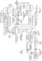
- FIGS 1-3 show embodiments of an energy conversion system and parts thereof according to the invention.
- the energy conversion system according to the invention comprises:
- the energy conversion system comprises a high-pressure Solid Oxide Fuel Cell (SOFC) A with a semi-closed oxy-combustion Brayton cycle using CO 2 as moderator of the combustion temperature.
- SOFC Solid Oxide Fuel Cell
- the maximum cycle pressure and the SOFC unit A operating pressure are preferably above the critical pressure of CO 2 (i.e., > 73.9 bar).
- the semi-closed Brayton cycle is a supercritical CO 2 cycle with advantages in terms of efficiency.
- the energy conversion system can use either a gaseous or a liquid fuel 1.
- the fuel shall be pressurized, optionally preheated, then is fed to the anode of the SOFC unit A while the oxidant mixture containing CO 2 and O 2 4, preheated in a regenerative heat exchanger D , is fed to the SOFC cathode side.
- the SOFC unit A can be designed to run either with or without internal reforming (e.g., adopting specific catalysts, such as Ni-based materials typically used for commercially available SOFCs ), depending on the type of fuel to be used; in the case of natural gas feeding, methane is converted into hydrogen within the cell according to the reactions of steam reforming and water gas shift:
- the reforming reaction which is highly endothermic, occurs exploiting available heat from the cell losses (thus converting heat into chemical energy, with an advantage for the system electric efficiency) and is driven by the consumption of hydrogen allowed by the electrochemical reactions (Eq. 1,2).
- Steam required for hydrocarbons reforming can be supplied directly stream 3 and/or through recycling a fraction of the stream exiting the anode 40.
- an ejector (O) or a fan X capable of withstanding high gas temperatures can provide the pressure head required to sustain the stream recycle.
- the compressed fuel entering the power plant can therefore be mixed with part of the stream recycled from the anode outlet 40 and/or with steam 3 (which can be generated in the heat exchanger D ). Then, the stream entering the anode side can be preheated within the SOFC unit A to the final operating temperature (e.g., 700 - 850 °C) using the thermal power made available by the electrochemical process, through either a dedicated heat exchanger P (e.g., cooling the product streams) or internally in the fuel cell stack.
- a dedicated heat exchanger P e.g., cooling the product streams
- the SOFC unit can be fed directly with methane without needing a preliminary mixing with steam or recycled anode exhaust.
- the unconverted fuel and oxygen leaving the SOFC unit A are sent to the combustor unit B of the semi-closed cycle.
- the combustor unit B of the semi-closed cycle.
- the combustion products 10 are mainly CO 2 and H 2 O, and may contain also some amounts of O 2 , Ar, N 2 and other chemical species.
- the product gases are expanded in an expander C to a lower pressure, indicatively in the range 1 - 50 bar.
- a lower pressure indicatively in the range 1 - 50 bar.
- such value depends on the other pressures and temperatures of the cycle, and it may not be limited to such range.
- the turbine inlet temperature can be higher or lower, requiring to adopt a cooled or uncooled expander C.
- the cooling flows 11 can be taken from the stream of recycled CO 2 and can be preheated in the regenerator D.
- the product gases 10 leaving the turbine are cooled in the regenerator D and then in a cooler E to a temperature approaching that of the heat sink (e.g., lake, river, sea, air, cold streams of other plants).
- Most of the H 2 O of the product gases condenses, and it is separated with a gas-liquid separator F , such as a flash drum.
- the outlet gas stream leaving the separator 16 is rich in CO 2 .
- a fraction can be recycled 18 to be used as temperature moderator and/or to be mixed with the oxygen stream 21 and/or used as turbine cooling flow 11 while the remaining part 17 can be separated and either vented into the atmosphere or sent to the CO 2 purification and utilization/storage system.
- compressing the recycle CO 2 -rich stream above the critical pressure if water condenses, it is possible to use a liquid-liquid separation process to remove further water.
- CO 2 purification unit a conventional plant capable of producing nearly pure liquid CO 2 .
- regenerator D It is also possible to recover heat in the regenerator D from the main compressor of the Air Separation Unit (ASU) and/or the intercoolers of the compressors H,K,L and/or from nearby heat sources. This can result in a further improvement of the efficiency of the proposed energy conversion system.
- ASU Air Separation Unit
- Table 1 indicative ranges of operating pressures and temperatures for the key streams.
- Type of parameter Operating range Working pressure of the SOFC (A) and combustor (B) units 5 - 500 bar Expander (C) outlet pressure 1 - 50 bar
- a second oxidation stage after the expansion (reheating configuration), adding a second SOFC unit AF and/or a second combustor unit AG optionally feeding additional fuel 61 and oxidant 62.
- the working fluid can be further expanded in a second expander AH before entering the regenerator AI (see Figure 3 ).
- This scheme can further increase the power output of the plant and lead to a lower specific investment cost (total plant cost / net electric power), specially for designs featuring one SOFC, two combustors and two expanders.
- This second embodiment could also feature a wider operational range thanks to the possibility of adjusting the fuel flow rate fed to the different SOFCs and/or combustors.
- Fuel is a natural gas with composition reported in Table 2: Table 2 - Composition of the fuel considered in the simulation example Type of molecule Composition, molar basis CH 4 89.00 % C 2 H 6 7.00 % C 3 H 8 1.00 % i-C 4 H 10 0.05 % n-C 4 H 10 0.05 % i-C 5 H 12 0.005 % n-C 5 H 12 0.005 % CO 2 2.00 % N 2 0.89 % - The oxygen is provided at 120 bar and 15 °C (288K), thus compressor H pressurizes stream 19 to 120 bar.
- - Stream 2 is liquid water at 15 °C (288K), 1.013 bar.
- the proposed system still can be designed and operated in a large variety of conditions due to the possibility of varying (i) the SOFC A unit and combustor B operative pressure, (ii) the expander C outlet pressure, (iii) the fraction of the unconverted fuel 40 recycled back to the anode inlet, (iv) the mass flow rate of the temperature moderator 9 of the combustor, (v) the regenerator outlet temperature of the oxidant 26 , temperature moderator 9 and steam 3 , (vi) the regenerator outlet temperature of the expander cooling flows 11 , and (vii) the fraction of the recycled 20 stream mixed with the oxygen to produce the oxidant flow.
- the above listed independent variables have been optimized using a systematic process optimization approach.
- the objective function to be maximized is the net electric efficiency (net electric power output of the integrated system divided the chemical power of the inlet fuel, LHV basis).
- the optimization constraints considered in this example are summarized in Table 3: Table 3 - Technical constraints considered in the optimization example.
- Parameter Value Concentration of oxygen at the SOFC cathode outlet (35) % mol (minimum) 10 % mol Concentration of water at the SOFC anode outlet (34) (maximum) 60 % mol
- Temperature difference within the regenerator (D) (minimum) 5 °C Temperature difference at the hot end of the regenerator (D) (min- imum) 20 °C Expander (C) allowed metal temperature (maximum) 860 °C C/O at the SOFC (A) anode inlet 2.5 -
- the oxidant, the temperature moderator and the steam for the SOFC unit exit the regenerator at the same temperature. Moreover, it is assumed that the oxidant provides 3 % excess of oxygen compared to the stoichiometric condition.
- the optimization problem has been tackled using an optimization algorithm specifically developed for process and energy system optimization purposes.
- the SOFC produces 72.7 % of the plant gross power output while the turbine accounts for the remaining 27.3 %.
- the intercooled compression and the ASU are the two major penalties, consuming 5.5 % and 12.0 % of the gross power output respectively.
- the resulting net electric efficiency is 76.2 % without CO 2 capture (i.e., venting the excess CO 2 not recycled), and 75.4 % with CO 2 capture.
- the resulting performance indexes are outstanding compared to state-of-the-art as well as advanced energy systems (with and without CO 2 capture) which feature efficiencies in the range 60 - 63 % for the systems without capture, and 40 - 46 % for the systems with capture.
Landscapes
- Engineering & Computer Science (AREA)
- Chemical & Material Sciences (AREA)
- Sustainable Development (AREA)
- Life Sciences & Earth Sciences (AREA)
- Chemical Kinetics & Catalysis (AREA)
- Sustainable Energy (AREA)
- Manufacturing & Machinery (AREA)
- Electrochemistry (AREA)
- General Chemical & Material Sciences (AREA)
- Combustion & Propulsion (AREA)
- Mechanical Engineering (AREA)
- General Engineering & Computer Science (AREA)
- Fuel Cell (AREA)
Priority Applications (1)
| Application Number | Priority Date | Filing Date | Title |
|---|---|---|---|
| HRP20241009TT HRP20241009T1 (hr) | 2019-12-16 | 2020-11-05 | Sustav pretvorbe energije |
Applications Claiming Priority (2)
| Application Number | Priority Date | Filing Date | Title |
|---|---|---|---|
| IT102019000024162A IT201900024162A1 (it) | 2019-12-16 | 2019-12-16 | Sistema di conversione di energia |
| PCT/EP2020/081054 WO2021121762A1 (en) | 2019-12-16 | 2020-11-05 | Energy conversion system |
Publications (2)
| Publication Number | Publication Date |
|---|---|
| EP4077898A1 EP4077898A1 (en) | 2022-10-26 |
| EP4077898B1 true EP4077898B1 (en) | 2024-06-19 |
Family
ID=69904110
Family Applications (1)
| Application Number | Title | Priority Date | Filing Date |
|---|---|---|---|
| EP20799724.8A Active EP4077898B1 (en) | 2019-12-16 | 2020-11-05 | Energy conversion system |
Country Status (9)
| Country | Link |
|---|---|
| US (1) | US20230030209A1 (pl) |
| EP (1) | EP4077898B1 (pl) |
| DK (1) | DK4077898T3 (pl) |
| ES (1) | ES2986608T3 (pl) |
| HR (1) | HRP20241009T1 (pl) |
| HU (1) | HUE067025T2 (pl) |
| IT (1) | IT201900024162A1 (pl) |
| PL (1) | PL4077898T3 (pl) |
| WO (1) | WO2021121762A1 (pl) |
Families Citing this family (2)
| Publication number | Priority date | Publication date | Assignee | Title |
|---|---|---|---|---|
| WO2020101929A1 (en) * | 2018-11-14 | 2020-05-22 | Precision Combustion, Inc. | Integrated power generation system |
| CN116706123A (zh) | 2023-07-24 | 2023-09-05 | 江苏科技大学 | 基于阴极与阳极再循环的sofc/gt/sco2混合动力系统 |
Family Cites Families (12)
| Publication number | Priority date | Publication date | Assignee | Title |
|---|---|---|---|---|
| DE50115748D1 (de) * | 2000-10-13 | 2011-02-03 | Alstom Technology Ltd | Verfahren zum Betrieb einer Kraftwerksanlage |
| US6868677B2 (en) * | 2001-05-24 | 2005-03-22 | Clean Energy Systems, Inc. | Combined fuel cell and fuel combustion power generation systems |
| US7067208B2 (en) * | 2002-02-20 | 2006-06-27 | Ion America Corporation | Load matched power generation system including a solid oxide fuel cell and a heat pump and an optional turbine |
| US7118818B2 (en) * | 2002-10-01 | 2006-10-10 | Rolls-Royce Plc | Solid oxide fuel cell system |
| US7306871B2 (en) | 2004-03-04 | 2007-12-11 | Delphi Technologies, Inc. | Hybrid power generating system combining a fuel cell and a gas turbine |
| US7709118B2 (en) | 2004-11-18 | 2010-05-04 | Siemens Energy, Inc. | Recuperated atmospheric SOFC/gas turbine hybrid cycle |
| CA2595880A1 (en) * | 2005-01-25 | 2006-08-03 | Nuvera Fuel Cells, Inc. | Fuel cell power plants |
| US7743861B2 (en) * | 2006-01-06 | 2010-06-29 | Delphi Technologies, Inc. | Hybrid solid oxide fuel cell and gas turbine electric generating system using liquid oxygen |
| US7862938B2 (en) * | 2007-02-05 | 2011-01-04 | Fuelcell Energy, Inc. | Integrated fuel cell and heat engine hybrid system for high efficiency power generation |
| WO2011001311A2 (en) | 2009-07-03 | 2011-01-06 | Ecole Polytechnique Federale De Lausanne (Epfl) | Hybrid cycle sofc - inverted gas turbine with co2 separation |
| GB2494667A (en) * | 2011-09-15 | 2013-03-20 | Rolls Royce Fuel Cell Systems Ltd | A solid oxide fuel cell system |
| JP6125224B2 (ja) * | 2012-12-25 | 2017-05-10 | 三菱日立パワーシステムズ株式会社 | 発電システム及び発電システムの運転方法 |
-
2019
- 2019-12-16 IT IT102019000024162A patent/IT201900024162A1/it unknown
-
2020
- 2020-11-05 WO PCT/EP2020/081054 patent/WO2021121762A1/en not_active Ceased
- 2020-11-05 ES ES20799724T patent/ES2986608T3/es active Active
- 2020-11-05 HU HUE20799724A patent/HUE067025T2/hu unknown
- 2020-11-05 DK DK20799724.8T patent/DK4077898T3/da active
- 2020-11-05 EP EP20799724.8A patent/EP4077898B1/en active Active
- 2020-11-05 HR HRP20241009TT patent/HRP20241009T1/hr unknown
- 2020-11-05 US US17/785,426 patent/US20230030209A1/en active Pending
- 2020-11-05 PL PL20799724.8T patent/PL4077898T3/pl unknown
Also Published As
| Publication number | Publication date |
|---|---|
| WO2021121762A1 (en) | 2021-06-24 |
| IT201900024162A1 (it) | 2021-06-16 |
| HRP20241009T1 (hr) | 2024-11-08 |
| DK4077898T3 (da) | 2024-07-01 |
| US20230030209A1 (en) | 2023-02-02 |
| ES2986608T3 (es) | 2024-11-12 |
| HUE067025T2 (hu) | 2024-09-28 |
| EP4077898A1 (en) | 2022-10-26 |
| PL4077898T3 (pl) | 2024-10-07 |
Similar Documents
| Publication | Publication Date | Title |
|---|---|---|
| Kvamsdal et al. | A quantitative comparison of gas turbine cycles with CO2 capture | |
| Kuchonthara et al. | Combinations of solid oxide fuel cell and several enhanced gas turbine cycles | |
| AU2001292544B2 (en) | Joint-cycle high-efficiency fuel cell system with power generating turbine | |
| Tola et al. | Low CO2 emissions chemically recuperated gas turbines fed by renewable methanol | |
| CA3022534C (en) | Methanation of anode exhaust gas to enhance carbon dioxide capture. | |
| EP2449229B1 (en) | Hybrid cycle sofc - inverted gas turbine with co2 separation | |
| EP1197639A2 (en) | Power palnt and method for operating the power plant | |
| KR101731051B1 (ko) | 고효율 초임계 이산화탄소 발전 시스템 및 그 방법 | |
| US9273607B2 (en) | Generating power using an ion transport membrane | |
| US20090229239A1 (en) | Integrated Pressurized Steam Hydrocarbon Reformer and Combined Cycle Process | |
| WO2003021702A1 (en) | A power generation apparatus | |
| EP4077898B1 (en) | Energy conversion system | |
| JP4632532B2 (ja) | 水素製造方法およびシステム | |
| Lozza et al. | Natural Gas Decarbonization to Reduce CO2 Emission From Combined Cycles: Part B—Steam-Methane Reforming | |
| US8850825B2 (en) | Generating power using an ion transport membrane | |
| US8733109B2 (en) | Combined fuel and air staged power generation system | |
| JP2000054852A (ja) | ガスタ―ビン複合サイクル発電システム | |
| US20250256957A1 (en) | Low-emission power generation system and method | |
| US11732651B2 (en) | Supercritical CO2 power cycle with dry reforming of methane | |
| US11492930B2 (en) | Power generation system with carbon capture | |
| Martinelli et al. | Simulation and Analysis of the Semi-Closed Solid Oxide CO2 Cycle (SOSCO2) for High Efficiency Ultra Low Carbon Power Generation | |
| Cammarata et al. | Simulation of the HiPowAR Gas-Steam Power Generation System Using Ammonia as Fuel | |
| Manente et al. | Methanol-fired Allam cycle: combining oxy-fuel power cycles with synthetic e-fuels | |
| Gambini et al. | Advanced Mixed Cycles based on Steam-Methane Reforming and Air Blown Combustion | |
| Kapoor et al. | Innovative Cycles for Industrial Combined Heat and Power Generation With Carbon Capture and Storage |
Legal Events
| Date | Code | Title | Description |
|---|---|---|---|
| REG | Reference to a national code |
Ref country code: HR Ref legal event code: TUEP Ref document number: P20241009T Country of ref document: HR |
|
| STAA | Information on the status of an ep patent application or granted ep patent |
Free format text: STATUS: UNKNOWN |
|
| STAA | Information on the status of an ep patent application or granted ep patent |
Free format text: STATUS: THE INTERNATIONAL PUBLICATION HAS BEEN MADE |
|
| PUAI | Public reference made under article 153(3) epc to a published international application that has entered the european phase |
Free format text: ORIGINAL CODE: 0009012 |
|
| STAA | Information on the status of an ep patent application or granted ep patent |
Free format text: STATUS: REQUEST FOR EXAMINATION WAS MADE |
|
| 17P | Request for examination filed |
Effective date: 20220614 |
|
| AK | Designated contracting states |
Kind code of ref document: A1 Designated state(s): AL AT BE BG CH CY CZ DE DK EE ES FI FR GB GR HR HU IE IS IT LI LT LU LV MC MK MT NL NO PL PT RO RS SE SI SK SM TR |
|
| DAV | Request for validation of the european patent (deleted) | ||
| DAX | Request for extension of the european patent (deleted) | ||
| STAA | Information on the status of an ep patent application or granted ep patent |
Free format text: STATUS: EXAMINATION IS IN PROGRESS |
|
| 17Q | First examination report despatched |
Effective date: 20230503 |
|
| P01 | Opt-out of the competence of the unified patent court (upc) registered |
Effective date: 20230615 |
|
| GRAP | Despatch of communication of intention to grant a patent |
Free format text: ORIGINAL CODE: EPIDOSNIGR1 |
|
| STAA | Information on the status of an ep patent application or granted ep patent |
Free format text: STATUS: GRANT OF PATENT IS INTENDED |
|
| INTG | Intention to grant announced |
Effective date: 20230929 |
|
| GRAJ | Information related to disapproval of communication of intention to grant by the applicant or resumption of examination proceedings by the epo deleted |
Free format text: ORIGINAL CODE: EPIDOSDIGR1 |
|
| STAA | Information on the status of an ep patent application or granted ep patent |
Free format text: STATUS: EXAMINATION IS IN PROGRESS |
|
| GRAP | Despatch of communication of intention to grant a patent |
Free format text: ORIGINAL CODE: EPIDOSNIGR1 |
|
| STAA | Information on the status of an ep patent application or granted ep patent |
Free format text: STATUS: GRANT OF PATENT IS INTENDED |
|
| INTC | Intention to grant announced (deleted) | ||
| INTG | Intention to grant announced |
Effective date: 20240130 |
|
| RAP1 | Party data changed (applicant data changed or rights of an application transferred) |
Owner name: ENI S.P.A. |
|
| GRAS | Grant fee paid |
Free format text: ORIGINAL CODE: EPIDOSNIGR3 |
|
| GRAA | (expected) grant |
Free format text: ORIGINAL CODE: 0009210 |
|
| STAA | Information on the status of an ep patent application or granted ep patent |
Free format text: STATUS: THE PATENT HAS BEEN GRANTED |
|
| AK | Designated contracting states |
Kind code of ref document: B1 Designated state(s): AL AT BE BG CH CY CZ DE DK EE ES FI FR GB GR HR HU IE IS IT LI LT LU LV MC MK MT NL NO PL PT RO RS SE SI SK SM TR |
|
| REG | Reference to a national code |
Ref country code: GB Ref legal event code: FG4D |
|
| REG | Reference to a national code |
Ref country code: CH Ref legal event code: EP |
|
| REG | Reference to a national code |
Ref country code: DK Ref legal event code: T3 Effective date: 20240628 |
|
| REG | Reference to a national code |
Ref country code: DE Ref legal event code: R096 Ref document number: 602020032708 Country of ref document: DE |
|
| REG | Reference to a national code |
Ref country code: SE Ref legal event code: TRGR |
|
| REG | Reference to a national code |
Ref country code: NL Ref legal event code: FP |
|
| REG | Reference to a national code |
Ref country code: HU Ref legal event code: AG4A Ref document number: E067025 Country of ref document: HU |
|
| PG25 | Lapsed in a contracting state [announced via postgrant information from national office to epo] |
Ref country code: FI Free format text: LAPSE BECAUSE OF FAILURE TO SUBMIT A TRANSLATION OF THE DESCRIPTION OR TO PAY THE FEE WITHIN THE PRESCRIBED TIME-LIMIT Effective date: 20240619 |
|
| REG | Reference to a national code |
Ref country code: LT Ref legal event code: MG9D |
|
| REG | Reference to a national code |
Ref country code: GR Ref legal event code: EP Ref document number: 20240401875 Country of ref document: GR Effective date: 20241007 |
|
| PG25 | Lapsed in a contracting state [announced via postgrant information from national office to epo] |
Ref country code: LV Free format text: LAPSE BECAUSE OF FAILURE TO SUBMIT A TRANSLATION OF THE DESCRIPTION OR TO PAY THE FEE WITHIN THE PRESCRIBED TIME-LIMIT Effective date: 20240619 |
|
| PG25 | Lapsed in a contracting state [announced via postgrant information from national office to epo] |
Ref country code: LV Free format text: LAPSE BECAUSE OF FAILURE TO SUBMIT A TRANSLATION OF THE DESCRIPTION OR TO PAY THE FEE WITHIN THE PRESCRIBED TIME-LIMIT Effective date: 20240619 Ref country code: FI Free format text: LAPSE BECAUSE OF FAILURE TO SUBMIT A TRANSLATION OF THE DESCRIPTION OR TO PAY THE FEE WITHIN THE PRESCRIBED TIME-LIMIT Effective date: 20240619 Ref country code: RS Free format text: LAPSE BECAUSE OF FAILURE TO SUBMIT A TRANSLATION OF THE DESCRIPTION OR TO PAY THE FEE WITHIN THE PRESCRIBED TIME-LIMIT Effective date: 20240919 |
|
| REG | Reference to a national code |
Ref country code: HR Ref legal event code: T1PR Ref document number: P20241009 Country of ref document: HR Ref country code: HR Ref legal event code: ODRP Ref document number: P20241009 Country of ref document: HR Payment date: 20241018 Year of fee payment: 5 |
|
| REG | Reference to a national code |
Ref country code: ES Ref legal event code: FG2A Ref document number: 2986608 Country of ref document: ES Kind code of ref document: T3 Effective date: 20241112 |
|
| REG | Reference to a national code |
Ref country code: AT Ref legal event code: MK05 Ref document number: 1696045 Country of ref document: AT Kind code of ref document: T Effective date: 20240619 |
|
| PG25 | Lapsed in a contracting state [announced via postgrant information from national office to epo] |
Ref country code: PT Free format text: LAPSE BECAUSE OF FAILURE TO SUBMIT A TRANSLATION OF THE DESCRIPTION OR TO PAY THE FEE WITHIN THE PRESCRIBED TIME-LIMIT Effective date: 20241021 |
|
| PG25 | Lapsed in a contracting state [announced via postgrant information from national office to epo] |
Ref country code: PT Free format text: LAPSE BECAUSE OF FAILURE TO SUBMIT A TRANSLATION OF THE DESCRIPTION OR TO PAY THE FEE WITHIN THE PRESCRIBED TIME-LIMIT Effective date: 20241021 |
|
| PG25 | Lapsed in a contracting state [announced via postgrant information from national office to epo] |
Ref country code: EE Free format text: LAPSE BECAUSE OF FAILURE TO SUBMIT A TRANSLATION OF THE DESCRIPTION OR TO PAY THE FEE WITHIN THE PRESCRIBED TIME-LIMIT Effective date: 20240619 |
|
| PG25 | Lapsed in a contracting state [announced via postgrant information from national office to epo] |
Ref country code: AT Free format text: LAPSE BECAUSE OF FAILURE TO SUBMIT A TRANSLATION OF THE DESCRIPTION OR TO PAY THE FEE WITHIN THE PRESCRIBED TIME-LIMIT Effective date: 20240619 |
|
| PG25 | Lapsed in a contracting state [announced via postgrant information from national office to epo] |
Ref country code: CZ Free format text: LAPSE BECAUSE OF FAILURE TO SUBMIT A TRANSLATION OF THE DESCRIPTION OR TO PAY THE FEE WITHIN THE PRESCRIBED TIME-LIMIT Effective date: 20240619 |
|
| PG25 | Lapsed in a contracting state [announced via postgrant information from national office to epo] |
Ref country code: SK Free format text: LAPSE BECAUSE OF FAILURE TO SUBMIT A TRANSLATION OF THE DESCRIPTION OR TO PAY THE FEE WITHIN THE PRESCRIBED TIME-LIMIT Effective date: 20240619 Ref country code: RO Free format text: LAPSE BECAUSE OF FAILURE TO SUBMIT A TRANSLATION OF THE DESCRIPTION OR TO PAY THE FEE WITHIN THE PRESCRIBED TIME-LIMIT Effective date: 20240619 |
|
| PG25 | Lapsed in a contracting state [announced via postgrant information from national office to epo] |
Ref country code: SM Free format text: LAPSE BECAUSE OF FAILURE TO SUBMIT A TRANSLATION OF THE DESCRIPTION OR TO PAY THE FEE WITHIN THE PRESCRIBED TIME-LIMIT Effective date: 20240619 |
|
| PG25 | Lapsed in a contracting state [announced via postgrant information from national office to epo] |
Ref country code: SM Free format text: LAPSE BECAUSE OF FAILURE TO SUBMIT A TRANSLATION OF THE DESCRIPTION OR TO PAY THE FEE WITHIN THE PRESCRIBED TIME-LIMIT Effective date: 20240619 Ref country code: SK Free format text: LAPSE BECAUSE OF FAILURE TO SUBMIT A TRANSLATION OF THE DESCRIPTION OR TO PAY THE FEE WITHIN THE PRESCRIBED TIME-LIMIT Effective date: 20240619 Ref country code: RO Free format text: LAPSE BECAUSE OF FAILURE TO SUBMIT A TRANSLATION OF THE DESCRIPTION OR TO PAY THE FEE WITHIN THE PRESCRIBED TIME-LIMIT Effective date: 20240619 Ref country code: EE Free format text: LAPSE BECAUSE OF FAILURE TO SUBMIT A TRANSLATION OF THE DESCRIPTION OR TO PAY THE FEE WITHIN THE PRESCRIBED TIME-LIMIT Effective date: 20240619 Ref country code: CZ Free format text: LAPSE BECAUSE OF FAILURE TO SUBMIT A TRANSLATION OF THE DESCRIPTION OR TO PAY THE FEE WITHIN THE PRESCRIBED TIME-LIMIT Effective date: 20240619 Ref country code: AT Free format text: LAPSE BECAUSE OF FAILURE TO SUBMIT A TRANSLATION OF THE DESCRIPTION OR TO PAY THE FEE WITHIN THE PRESCRIBED TIME-LIMIT Effective date: 20240619 |
|
| REG | Reference to a national code |
Ref country code: DE Ref legal event code: R097 Ref document number: 602020032708 Country of ref document: DE |
|
| PLBE | No opposition filed within time limit |
Free format text: ORIGINAL CODE: 0009261 |
|
| STAA | Information on the status of an ep patent application or granted ep patent |
Free format text: STATUS: NO OPPOSITION FILED WITHIN TIME LIMIT |
|
| 26N | No opposition filed |
Effective date: 20250320 |
|
| REG | Reference to a national code |
Ref country code: CH Ref legal event code: PL |
|
| PG25 | Lapsed in a contracting state [announced via postgrant information from national office to epo] |
Ref country code: MC Free format text: LAPSE BECAUSE OF FAILURE TO SUBMIT A TRANSLATION OF THE DESCRIPTION OR TO PAY THE FEE WITHIN THE PRESCRIBED TIME-LIMIT Effective date: 20240619 |
|
| PG25 | Lapsed in a contracting state [announced via postgrant information from national office to epo] |
Ref country code: LU Free format text: LAPSE BECAUSE OF NON-PAYMENT OF DUE FEES Effective date: 20241105 |
|
| REG | Reference to a national code |
Ref country code: CH Ref legal event code: PL |
|
| PG25 | Lapsed in a contracting state [announced via postgrant information from national office to epo] |
Ref country code: CH Free format text: LAPSE BECAUSE OF NON-PAYMENT OF DUE FEES Effective date: 20241130 |
|
| REG | Reference to a national code |
Ref country code: HR Ref legal event code: ODRP Ref document number: P20241009 Country of ref document: HR Payment date: 20251021 Year of fee payment: 6 |
|
| PGFP | Annual fee paid to national office [announced via postgrant information from national office to epo] |
Ref country code: HU Payment date: 20251029 Year of fee payment: 6 |
|
| PGFP | Annual fee paid to national office [announced via postgrant information from national office to epo] |
Ref country code: NL Payment date: 20251126 Year of fee payment: 6 |
|
| PGFP | Annual fee paid to national office [announced via postgrant information from national office to epo] |
Ref country code: IS Payment date: 20251104 Year of fee payment: 6 Ref country code: DE Payment date: 20251128 Year of fee payment: 6 |
|
| PGFP | Annual fee paid to national office [announced via postgrant information from national office to epo] |
Ref country code: GB Payment date: 20251127 Year of fee payment: 6 |
|
| PGFP | Annual fee paid to national office [announced via postgrant information from national office to epo] |
Ref country code: NO Payment date: 20251128 Year of fee payment: 6 |
|
| PGFP | Annual fee paid to national office [announced via postgrant information from national office to epo] |
Ref country code: IT Payment date: 20251119 Year of fee payment: 6 Ref country code: DK Payment date: 20251125 Year of fee payment: 6 |
|
| PGFP | Annual fee paid to national office [announced via postgrant information from national office to epo] |
Ref country code: HR Payment date: 20251021 Year of fee payment: 6 Ref country code: FR Payment date: 20251125 Year of fee payment: 6 |
|
| PGFP | Annual fee paid to national office [announced via postgrant information from national office to epo] |
Ref country code: GR Payment date: 20251126 Year of fee payment: 6 Ref country code: BE Payment date: 20251127 Year of fee payment: 6 |
|
| PGFP | Annual fee paid to national office [announced via postgrant information from national office to epo] |
Ref country code: SE Payment date: 20251127 Year of fee payment: 6 |
|
| PGFP | Annual fee paid to national office [announced via postgrant information from national office to epo] |
Ref country code: IE Payment date: 20251127 Year of fee payment: 6 Ref country code: CY Payment date: 20251029 Year of fee payment: 6 |
|
| PGFP | Annual fee paid to national office [announced via postgrant information from national office to epo] |
Ref country code: PL Payment date: 20251021 Year of fee payment: 6 Ref country code: BG Payment date: 20251113 Year of fee payment: 6 |
|
| PGFP | Annual fee paid to national office [announced via postgrant information from national office to epo] |
Ref country code: ES Payment date: 20251201 Year of fee payment: 6 |