EP4077102B1 - A method for controlling a wheel axle assembly - Google Patents
A method for controlling a wheel axle assembly Download PDFInfo
- Publication number
- EP4077102B1 EP4077102B1 EP19832609.2A EP19832609A EP4077102B1 EP 4077102 B1 EP4077102 B1 EP 4077102B1 EP 19832609 A EP19832609 A EP 19832609A EP 4077102 B1 EP4077102 B1 EP 4077102B1
- Authority
- EP
- European Patent Office
- Prior art keywords
- wheel axle
- vehicle
- reaction actuator
- adjustable reaction
- condition
- Prior art date
- Legal status (The legal status is an assumption and is not a legal conclusion. Google has not performed a legal analysis and makes no representation as to the accuracy of the status listed.)
- Active
Links
Images
Classifications
-
- B—PERFORMING OPERATIONS; TRANSPORTING
- B60—VEHICLES IN GENERAL
- B60Q—ARRANGEMENT OF SIGNALLING OR LIGHTING DEVICES, THE MOUNTING OR SUPPORTING THEREOF OR CIRCUITS THEREFOR, FOR VEHICLES IN GENERAL
- B60Q9/00—Arrangement or adaptation of signal devices not provided for in one of main groups B60Q1/00 - B60Q7/00, e.g. haptic signalling
-
- B—PERFORMING OPERATIONS; TRANSPORTING
- B62—LAND VEHICLES FOR TRAVELLING OTHERWISE THAN ON RAILS
- B62D—MOTOR VEHICLES; TRAILERS
- B62D7/00—Steering linkage; Stub axles or their mountings
- B62D7/06—Steering linkage; Stub axles or their mountings for individually-pivoted wheels, e.g. on king-pins
- B62D7/14—Steering linkage; Stub axles or their mountings for individually-pivoted wheels, e.g. on king-pins the pivotal axes being situated in more than one plane transverse to the longitudinal centre line of the vehicle, e.g. all-wheel steering
- B62D7/142—Steering linkage; Stub axles or their mountings for individually-pivoted wheels, e.g. on king-pins the pivotal axes being situated in more than one plane transverse to the longitudinal centre line of the vehicle, e.g. all-wheel steering specially adapted for particular vehicles, e.g. tractors, carts, earth-moving vehicles, trucks
-
- B—PERFORMING OPERATIONS; TRANSPORTING
- B62—LAND VEHICLES FOR TRAVELLING OTHERWISE THAN ON RAILS
- B62D—MOTOR VEHICLES; TRAILERS
- B62D7/00—Steering linkage; Stub axles or their mountings
- B62D7/06—Steering linkage; Stub axles or their mountings for individually-pivoted wheels, e.g. on king-pins
- B62D7/14—Steering linkage; Stub axles or their mountings for individually-pivoted wheels, e.g. on king-pins the pivotal axes being situated in more than one plane transverse to the longitudinal centre line of the vehicle, e.g. all-wheel steering
- B62D7/15—Steering linkage; Stub axles or their mountings for individually-pivoted wheels, e.g. on king-pins the pivotal axes being situated in more than one plane transverse to the longitudinal centre line of the vehicle, e.g. all-wheel steering characterised by means varying the ratio between the steering angles of the steered wheels
- B62D7/159—Steering linkage; Stub axles or their mountings for individually-pivoted wheels, e.g. on king-pins the pivotal axes being situated in more than one plane transverse to the longitudinal centre line of the vehicle, e.g. all-wheel steering characterised by means varying the ratio between the steering angles of the steered wheels characterised by computing methods or stabilisation processes or systems, e.g. responding to yaw rate, lateral wind, load, road condition
Definitions
- the invention relates to a method for controlling a wheel axle assembly of a vehicle. Moreover, the present invention relates to a control unit for controlling a wheel axle assembly of a vehicle. Furthermore, the present invention relates to a vehicle.
- the invention can be applied in heavy-duty vehicles, such as trucks, buses and construction equipment. Although the invention will be described with respect to a truck, the invention is not restricted to this particular vehicle, but may also be used in other vehicles such as buses or working machines.
- the rolling resistance of a vehicle may contribute to the energy consumption of a vehicle.
- US 2010/0198441 A1 proposes that the toe angle of steerable wheels of a vehicle be controlled.
- EP 0 468 567 A1 relates to a vehicle that has a rigid shaft mounted in bearing means, which rigid shaft has ends connected to length-adjustable reaction-force elements for influencing the rotation position of the shaft in dependence on a desired change in the direction of motion of the vehicle.
- a means is provided for supplying a signal which is dependent on the speed of the vehicle. Said speed dependent signal is led to a processing device, which device is connected to said elements for only allowing said elements to access a signal dependent on the desired change of direction if the speed of the vehicle is less than a certain adjustable value.
- DE4428342A1 A relates to a device for controlling a rear-wheel steering system includes a controller which carries out a delay process of the first order.
- This process is equivalent to a transmission function of a delay of the first order and is constituted by a time constant which preference to loading data from a rear-wheel travel sensor and a proportional constant which corresponds to vehicle speed data from a vehicle speed sensor.
- the delay process of the first order is carried out on a front-wheel steering angle which is obtained on the basis of steering-wheel angle data from a steering-wheel angle sensor in order thereby to fix a desired rear-wheel steering angle.
- Rear wheels are steered with the fixed rear-wheel steering angle with a quantity for the delay of the first order corresponding to the load.
- WO2018/010799 relates to a vehicle, comprising: a chassis; a steerable driven rear axle, wherein the steerable driven rear axle is pivotally mounted, such that the steerable driven rear axle may be rotated relative to the chassis about a vertical axis; air suspension struts adapted to suspend the steerable driven rear axle; and steering actuators adapted to rotate the steerable driven rear axle about the vertical axis.
- the present invention also relates to a method and kit for providing steering of a driven rear axle of a vehicle.
- An object of the invention is to provide a method for controlling a wheel axle assembly of a vehicle, which method can result in an appropriately low rolling resistance in a straightforward manner.
- the above object is achieved by a method according to claim 1.
- the present invention relates to a method for controlling a wheel axle assembly.
- the vehicle comprises a vehicle body with a longitudinal axis extending in a longitudinal direction, a transversal axis extending in a transversal direction and a vertical axis extending in a vertical direction.
- the longitudinal axis, the transversal axis and the vertical axis are perpendicular to each other.
- the longitudinal direction corresponds to an intended direction of travel of the vehicle and the vertical direction is parallel to a vertical line when the vehicle is positioned on a flat horizontally extending surface.
- the vehicle body comprises a vehicle body centre plane extending along the longitudinal axis and the vertical axis and separating the vehicle body into two body halves.
- the wheel axle assembly comprises a wheel axle and at least a first and a second wheel.
- the first and second wheels are located on opposite sides of the vehicle body centre plane.
- the wheel axle has a wheel axle centreline extending in a direction between the first and second wheels.
- the wheel axle assembly is pivotally connected to the vehicle body around a pivot axis such that a wheel axle angle, being an angle between the wheel axle centreline and a line extending parallel to the transversal axis, can be varied.
- the vehicle further comprises an adjustable reaction actuator connecting a portion of the vehicle body to a portion of the wheel axle whereby the condition of the adjustable reaction actuator controls the wheel axle angle.
- the method according the first aspect of the invention comprises determining a current vehicle operating condition and controlling the adjustable reaction actuator to assume a low roll resistance condition on the basis of the determined vehicle operating condition.
- the low roll resistance condition results in a rolling resistance of the wheel axle assembly being equal to or below a desired rolling resistance value.
- the wheel axle angle defined as above, can be modified in dependence of determined vehicle operating condition.
- the rolling resistance can be reduced by controlling the above-mentioned wheel axle angle.
- the method of the present invention may imply an appropriately low wear level of the wheels of the vehicle.
- determining the current vehicle operating condition comprises determining a current speed of the vehicle.
- the current speed may be useful information when controlling the adjustable reaction actuator.
- determining the current vehicle operating condition comprises determining an axle load imparted on the wheel axle assembly.
- the axle load may be useful information when controlling the adjustable reaction actuator.
- determining the current vehicle operating condition comprises determining ground condition information indicative of the condition of the ground on which the vehicle currently is travelling.
- the ground condition information comprises information indicative of the magnitude and/or direction of the inclination of the ground on which the vehicle currently is travelling.
- the ground condition information such as magnitude and/or direction of the inclination of the ground, may be useful information when controlling the adjustable reaction actuator. For instance, if the vehicle is travelling on a sideway inclining road segment, such as a cambered road segment, the rolling resistance may be kept appropriately low if the control of the adjustable reaction actuator takes such an inclination into account.
- determining the current vehicle operating condition comprises determining a load imparted on the adjustable reaction actuator.
- the load imparted on the adjustable reaction actuator may be used as a measure indicative of the rolling resistance which in turn implies an appropriate control of the adjustable reaction actuator.
- the method comprises varying the condition of the adjustable reaction actuator and detecting a resulting load imparted on the adjustable reaction actuator until the resulting load imparted on the adjustable reaction actuator is equal to or below a desired load value.
- the wheel axle angle may be varied until an appropriately low rolling resistance, indicated by a resulting load value equal to or below the desired load value, is obtained.
- the resulting load imparted on the adjustable reaction actuator may be used as a measure indicative of the rolling resistance and the desired load value may be used as the desired rolling resistance value.
- the vehicle comprises a propulsion assembly adapted to propel at least the wheels comprised in the wheel axle assembly.
- the method comprises ensuring that the wheel axle assembly is operated in a free rolling condition in which at least the wheels comprised in the wheel axle assembly are unpowered by, preferably disconnected from, the propulsion assembly when varying the condition of the adjustable reaction actuator and detecting a resulting load imparted on the adjustable reaction actuator until the resulting load imparted on the adjustable reaction actuator is equal to or below a desired load value.
- the wheel axle assembly is operated in the free rolling condition, it may be straightforward to relate the resulting load imparted on the adjustable reaction actuator to the rolling resistance of the wheel axle assembly.
- the method further comprises comparing the resulting load imparted on the adjustable reaction actuator to a load threshold value and in response to the resulting load imparted on the adjustable reaction actuator being equal to or exceeding the load threshold value, issuing a warning signal, preferably issuing a warning signal to an operator of the vehicle.
- a warning signal preferably issuing a warning signal to an operator of the vehicle.
- the adjustable reaction actuator is hydraulically adjustable or electrically adjustable.
- each one of the wheels of the wheel axle assembly is connected to the wheel axle such that a fixed steering angle between the wheel and the wheel axle is obtained.
- the wheels of the wheel axle assembly are not steerable wheels.
- a second aspect of the present invention relates to a control unit for controlling a wheel axle assembly of a vehicle.
- the vehicle comprises a vehicle body with a longitudinal axis extending in a longitudinal direction, a transversal axis extending in a transversal direction and a vertical axis extending in a vertical direction.
- the longitudinal axis, the transversal axis and the vertical axis are perpendicular to each other.
- the longitudinal direction corresponds to an intended direction of travel of the vehicle and the vertical direction is parallel to a vertical line when the vehicle is positioned on a flat horizontally extending surface.
- the vehicle body comprises a vehicle body centre plane extending along the longitudinal axis and the vertical axis and separating the vehicle body into two body halves.
- the wheel axle assembly comprises a wheel axle and at least a first and a second wheel.
- the first and second wheels are located on opposite sides of the vehicle body centre plane.
- the wheel axle has a wheel axle centreline extending in a direction between the first and second wheels.
- the wheel axle assembly is pivotally connected to the vehicle body around a pivot axis such that a wheel axle angle, being an angle between the wheel axle centreline and a line extending parallel to the transversal axis, can be varied.
- the vehicle further comprises an adjustable reaction actuator connecting a portion of the vehicle body to a portion of the wheel axle whereby the condition of the adjustable reaction actuator controls the wheel axle angle.
- the control unit is adapted to receive vehicle operating information indicative of a current vehicle operating condition and to issue a control signal to the adjustable reaction actuator to assume a low roll resistance condition on the basis of the received vehicle operating information.
- the low roll resistance condition results in a rolling resistance of the wheel axle assembly being equal to or below a desired rolling resistance value.
- the vehicle operating information comprises information indicative of a current speed of the vehicle.
- the vehicle operating information comprises information indicative of an axle load imparted on the wheel axle assembly.
- the vehicle operating information comprises ground condition information indicative of the condition of the ground on which the vehicle currently is travelling.
- the ground condition information comprises information indicative of the magnitude and/or direction of the inclination of the ground on which the vehicle currently is travelling.
- the vehicle operating information comprises information indicative of a load imparted on the adjustable reaction actuator.
- control unit is adapted to issue the control signal to the adjustable reaction actuator such that the condition of the adjustable reaction actuator is varied and receive information indicative of a resulting load imparted on the adjustable reaction actuator until the resulting load imparted on the adjustable reaction actuator is equal to or below a desired load value.
- the vehicle comprises a propulsion assembly adapted to propel at least the wheels comprised in the wheel axle assembly
- the control unit being adapted to receive information indicative of that the wheel axle assembly is operated in a free rolling condition in which at least the wheels comprised in the wheel axle assembly are unpowered by, preferably disconnected from, the propulsion assembly and in response thereto issue the control signal to the adjustable reaction actuator such that the condition of the adjustable reaction actuator is varied and receive information indicative of a resulting load imparted on the adjustable reaction actuator until the resulting load imparted on the adjustable reaction actuator is equal to or below a desired load value.
- control unit is adapted to compare said resulting load imparted on said adjustable reaction actuator to a load threshold value and in response to said resulting load imparted on said adjustable reaction actuator being equal to or exceeding said load threshold value, issue a warning signal, preferably issue a warning signal to an operator of the vehicle.
- a third aspect of the present invention relates to a vehicle comprising a vehicle body with a longitudinal axis extending in a longitudinal direction, a transversal axis extending in a transversal direction and a vertical axis extending in a vertical direction.
- the longitudinal axis, the transversal axis and the vertical axis are perpendicular to each other.
- the longitudinal direction corresponds to an intended direction of travel of the vehicle and the vertical direction is parallel to a vertical line when the vehicle is positioned on a flat horizontally extending surface.
- the vehicle body comprises a vehicle body centre plane extending along the longitudinal axis and the vertical axis and separating the vehicle body into two body halves.
- the wheel axle assembly comprises a wheel axle and at least a first and a second wheel.
- the first and second wheels are located on opposite sides of the vehicle body centre plane.
- the wheel axle has a wheel axle centreline extending in a direction between the first and second wheels.
- the wheel axle assembly is pivotally connected to the vehicle body around a pivot axis such that a wheel axle angle, being an angle between the wheel axle centreline and a line extending parallel to the transversal axis, can be varied.
- the vehicle further comprises an adjustable reaction actuator connecting a portion of the vehicle body to a portion of the wheel axle whereby a condition of the adjustable reaction actuator controls the wheel axle angle.
- the vehicle according to the third aspect of the present invention comprises a control unit according to the second aspect of the present invention.
- the adjustable reaction actuator is hydraulically adjustable or electrically adjustable.
- each one of the wheels of the wheel axle assembly is connected to the wheel axle such that a fixed steering angle between the wheel and the wheel axle is obtained.
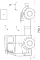
- the invention will be described below for a vehicle in the form of a truck 10 such as the truck illustrated in Fig. 1 .
- the truck 10 should be seen as an example of a vehicle for which the method according to the present invention could be carried out or which vehicle could comprise the control unit according to the present invention.
- the method or control unit may be implemented in a plurality of different types of vehicles, such as a truck, a tractor, a car, a bus, a work machine such as a wheel loader or any other type of construction equipment.
- the vehicle 10 comprises a vehicle body 12 with a longitudinal axis L extending in a longitudinal direction, a transversal axis T extending in a transversal direction and a vertical axis V extending in a vertical direction.
- the longitudinal axis L, the transversal axis T and the vertical axis V are perpendicular to each other.
- the longitudinal direction L corresponds to an intended direction of travel of the vehicle and the vertical direction V is parallel to a vertical line when the vehicle is positioned on a flat horizontally extending surface 14.
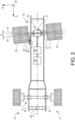
- Fig. 2 is a top view of a vehicle body 12, such as the Fig. 1 vehicle body 12.
- the vehicle body 12 comprises a vehicle body centre plane P (such a plane is also indicated in Fig. 1 ) extending along the longitudinal axis L and the vertical axis V and separating the vehicle body 12 into two body halves 15, 16, viz a first body half 15 and a second body half 16.
- Fig. 2 further illustrates a wheel axle assembly 18 comprising a wheel axle 20 and at least a first wheel 22 and a second wheel 24.
- the first and second wheels 22, 24 are located on opposite sides of the vehicle body centre plane P.
- the wheel axle assembly 18 comprises two wheels 22, 26 in the first body half 15 and two wheels 24, 28 in the second body half 16.
- the wheel axle 20 has a wheel axle centreline 30 extending in a direction between the first and second wheels 22, 24.
- each one of the wheels 22, 24, 26, 28 of the wheel axle assembly 18 is connected to the wheel axle 20 such that a fixed steering angle between the wheel and the wheel axle is obtained.
- the wheel axle assembly 18 is pivotally connected to the vehicle body 12 around a pivot axis 31 such that a wheel axle angle 32, being an angle between the wheel axle centreline 30 and a line 34 extending parallel to the transversal axis T, can be varied.
- the vehicle 10 further comprises an adjustable reaction actuator 36 connecting a portion of the vehicle body 12 to a portion of the wheel axle 20 whereby a condition of the adjustable reaction actuator 36 controls the wheel axle angle 32.
- the pivot axis 31 may extend in a direction parallel to the vertical axis V.
- the adjustable reaction actuator 36 is implemented as an adjustable reaction actuator rod.
- the condition of the adjustable reaction actuator 36 that controls the wheel axle angle 32 is the length of the adjustable reaction rod.
- the adjustable reaction actuator 36 may be adapted to impart a pivoting moment on the wheel axle assembly 18 to thereby alter the wheel axle angle 32.
- the adjustable reaction actuator 36 may be hydraulically adjustable or electrically adjustable.
- the adjustable reaction actuator 36 comprises a load sensing unit 38 adapted to detect an imparted load on the adjustable reaction actuator 36.
- the detected load may be a linear load, i.e. a force, or a moment.
- the detected load may be a detected hydraulic pressure, e.g. a detected hydraulic pressure in a chamber (not shown) of the actuator 36.
- the vehicle 10 may comprise a control unit 40 which is preferably an electronic control unit.
- the control unit 40 may be adapted to receive information from one or more sensors.
- the one or more sensors may include at least one of a vehicle speed sensor 42, an axle load sensor 43 adapted to determine a load imparted on the wheel axle assembly 18 and a ground condition sensor 44.
- the ground condition sensor 44 may comprise an inclinometer (not shown) and/or means for determining the current position of the vehicle 10.
- the one or more sensors may include the load sensing unit 38 mentioned above.
- control unit 40 may be in communication, through wireless and/or wire based communication means, to the relevant sensors 38, 42, 44.
- Fig. 2 illustrates that the vehicle comprises a propulsion assembly 46 adapted to propel at least the wheels 22, 24, 26, 28 comprised in the wheel axle assembly 18.
- the propulsion assembly 46 may comprise an internal combustion engine and/or an electric motor.
- the vehicle 10 may comprise a clutch assembly 48 for selectively drivingly connecting the propulsion assembly 46 to the wheel axle assembly 18.
- the control unit 40 is adapted to receive vehicle operating information indicative of a current vehicle operating condition and to issue a control signal to the adjustable reaction actuator 36 to assume a low roll resistance condition on the basis of the received vehicle operating information.
- the low roll resistance condition results in a rolling resistance of the wheel axle assembly 18 being equal to or below a desired rolling resistance value.
- the rolling resistance may be defined as the force required to move the vehicle on the current ground and at the current speed.
- the rolling resistance, as well as the rolling resistance value may be expressed in terms of a force, e.g. in terms of Newtons.
- the rolling resistance may be defined as the force per unit vehicle weight required to move the vehicle on the current ground and at the current speed.
- the rolling resistance, as well as the rolling resistance value may be expressed in terms of a force per unit weight, e.g. in terms of Newtons / kilograms.
- the vehicle operating information may comprise information indicative of at least one of the following: current speed of the vehicle, an axle load imparted on the wheel axle assembly 18 and the condition of the ground on which the vehicle 10 currently is travelling.
- the control unit 40 may receive relevant information from the previously mentioned sensors 42, 43, 44.
- the control unit may further use a look-up table and/or an equation for determining the low roll resistance condition on the basis of the received vehicle operating information.
- the ground condition information may comprise information indicative of the magnitude and/or direction of the inclination of the ground on which the vehicle 10 currently is travelling.
- the vehicle operating information may comprise information indicative of a load imparted on the adjustable reaction actuator 36.
- the control unit 40 may be adapted to receive relevant information from the previously mentioned load sensing unit 38.
- control unit 40 may be adapted to issue the control signal to the adjustable reaction actuator 36 such that the condition of the adjustable reaction actuator is varied, resulting in that the wheel axle angle 32 is varied, and receive information indicative of a resulting load imparted on the adjustable reaction actuator 36 until the resulting load imparted on the adjustable reaction actuator 36 is equal to or below a desired load value.
- control unit 40 may be adapted to issue the control signal to the adjustable reaction actuator 36 such that the condition of the adjustable reaction actuator is varied and receive information indicative of a resulting load imparted on the adjustable reaction actuator 36 until a minimum resulting load imparted on the adjustable reaction actuator 36 is obtained.
- the vehicle 10 comprises a propulsion assembly 46 adapted to propel at least the wheels 22, 24, 26, 28 comprised in the wheel axle assembly 18.
- control unit 40 may be adapted to receive information indicative of that the wheel axle assembly 18 is operated in a free rolling condition in which at least the wheels 22, 24, 26, 28 comprised in the wheel axle assembly 18 are unpowered by, preferably disconnected from, the propulsion assembly 46.
- the control unit 40 may be adapted to receive information from the clutch assembly 48 that the propulsion assembly 46 is disconnected from the wheel axle assembly 18.
- the control unit 40 may be adapted issue a control signal to the clutch assembly 48 such that the propulsion assembly 46 is disconnected from the wheel axle assembly 18.
- the free rolling condition may be such that each wheel of the vehicle 10 is unpowered by, preferably disconnected from, the propulsion assembly 46.
- control unit 40 may further be adapted to, in response to receiving information indicative of that said wheel axle assembly 18 is operated in a free rolling condition, issue the control signal to the adjustable reaction actuator 36 such that the condition of the adjustable reaction actuator 36 is varied and receive information indicative of a resulting load imparted on the adjustable reaction actuator 36 until the resulting load imparted on the adjustable reaction actuator 36 is equal to or below a desired load value.
- control unit 40 may be adapted to, in response to receiving information indicative of that said wheel axle assembly 18 is operated in a free rolling condition, issue the control signal to the adjustable reaction actuator 36 such that the condition of the adjustable reaction actuator is varied and receive information indicative of a resulting load imparted on the adjustable reaction actuator 36 until a minimum resulting load imparted on the adjustable reaction actuator 36 is obtained.
- control unit 40 may be adapted to compare the resulting load imparted on the adjustable reaction actuator 36 to a load threshold value and in response to the resulting load imparted on the adjustable reaction actuator 36 being equal to or exceeding the load threshold value, issue a warning signal, preferably issue a warning signal to an operator of the vehicle 10.
- a malfunctioning wheel axle assembly 18 may for instance be occasioned by a wheel puncture and/or a malfunctioning brake system (not shown).
- control unit 40 has been presented hereinabove with reference to one wheel axle assembly 18, it is of course envisaged that embodiments of the control unit 40 may be adapted to issue control signals to a plurality of wheel axle assemblies for vehicles comprising a plurality of wheel axle assemblies.
- control unit 40 may be adapted to issue control signals to a plurality of wheel axle assemblies for vehicles comprising a plurality of wheel axle assemblies.
- method and/or vehicle according to the present invention has been presented hereinabove with reference to one wheel axle assembly 18, it is of course envisaged that embodiments of the method and/or vehicle may control each one of a plurality of wheel axle assemblies.
Landscapes
- Engineering & Computer Science (AREA)
- Mechanical Engineering (AREA)
- Chemical & Material Sciences (AREA)
- Combustion & Propulsion (AREA)
- Transportation (AREA)
- Physics & Mathematics (AREA)
- Mathematical Physics (AREA)
- Theoretical Computer Science (AREA)
- Human Computer Interaction (AREA)
- Vehicle Body Suspensions (AREA)
Description
- The invention relates to a method for controlling a wheel axle assembly of a vehicle. Moreover, the present invention relates to a control unit for controlling a wheel axle assembly of a vehicle. Furthermore, the present invention relates to a vehicle.
- The invention can be applied in heavy-duty vehicles, such as trucks, buses and construction equipment. Although the invention will be described with respect to a truck, the invention is not restricted to this particular vehicle, but may also be used in other vehicles such as buses or working machines.
- The rolling resistance of a vehicle may contribute to the energy consumption of a vehicle. In order to keep the rolling resistance appropriately low,
US 2010/0198441 A1 proposes that the toe angle of steerable wheels of a vehicle be controlled. However, there is still a need for improving methods and systems for reducing rolling resistance. - According to its abstract,
EP 0 468 567 A1 relates to a vehicle that has a rigid shaft mounted in bearing means, which rigid shaft has ends connected to length-adjustable reaction-force elements for influencing the rotation position of the shaft in dependence on a desired change in the direction of motion of the vehicle. A means is provided for supplying a signal which is dependent on the speed of the vehicle. Said speed dependent signal is led to a processing device, which device is connected to said elements for only allowing said elements to access a signal dependent on the desired change of direction if the speed of the vehicle is less than a certain adjustable value. - According to its abstract,
DE4428342A1 A relates to a device for controlling a rear-wheel steering system includes a controller which carries out a delay process of the first order. This process is equivalent to a transmission function of a delay of the first order and is constituted by a time constant which preference to loading data from a rear-wheel travel sensor and a proportional constant which corresponds to vehicle speed data from a vehicle speed sensor. The delay process of the first order is carried out on a front-wheel steering angle which is obtained on the basis of steering-wheel angle data from a steering-wheel angle sensor in order thereby to fix a desired rear-wheel steering angle. Rear wheels are steered with the fixed rear-wheel steering angle with a quantity for the delay of the first order corresponding to the load. As a result, driving stability and the turning performance of the front part of a vehicle are improved under different loading and steering conditions. - According to its abstract,
WO2018/010799 relates to a vehicle, comprising: a chassis; a steerable driven rear axle, wherein the steerable driven rear axle is pivotally mounted, such that the steerable driven rear axle may be rotated relative to the chassis about a vertical axis; air suspension struts adapted to suspend the steerable driven rear axle; and steering actuators adapted to rotate the steerable driven rear axle about the vertical axis. The present invention also relates to a method and kit for providing steering of a driven rear axle of a vehicle. - SUMMARY An object of the invention is to provide a method for controlling a wheel axle assembly of a vehicle, which method can result in an appropriately low rolling resistance in a straightforward manner.
- According to a first aspect of the invention, the above object is achieved by a method according to claim 1.
- As such, the present invention relates to a method for controlling a wheel axle assembly.
- The vehicle comprises a vehicle body with a longitudinal axis extending in a longitudinal direction, a transversal axis extending in a transversal direction and a vertical axis extending in a vertical direction. The longitudinal axis, the transversal axis and the vertical axis are perpendicular to each other.
- The longitudinal direction corresponds to an intended direction of travel of the vehicle and the vertical direction is parallel to a vertical line when the vehicle is positioned on a flat horizontally extending surface.
- The vehicle body comprises a vehicle body centre plane extending along the longitudinal axis and the vertical axis and separating the vehicle body into two body halves. The wheel axle assembly comprises a wheel axle and at least a first and a second wheel. The first and second wheels are located on opposite sides of the vehicle body centre plane. The wheel axle has a wheel axle centreline extending in a direction between the first and second wheels.
- The wheel axle assembly is pivotally connected to the vehicle body around a pivot axis such that a wheel axle angle, being an angle between the wheel axle centreline and a line extending parallel to the transversal axis, can be varied.
- The vehicle further comprises an adjustable reaction actuator connecting a portion of the vehicle body to a portion of the wheel axle whereby the condition of the adjustable reaction actuator controls the wheel axle angle.
- The method according the first aspect of the invention comprises determining a current vehicle operating condition and controlling the adjustable reaction actuator to assume a low roll resistance condition on the basis of the determined vehicle operating condition. The low roll resistance condition results in a rolling resistance of the wheel axle assembly being equal to or below a desired rolling resistance value.
- Thus, what the inventor of the present invention has realized is that the wheel axle angle, defined as above, can be modified in dependence of determined vehicle operating condition. Thus, instead of, or in addition to, controlling the toe angle for steerable wheels, the rolling resistance can be reduced by controlling the above-mentioned wheel axle angle. Moreover, the method of the present invention may imply an appropriately low wear level of the wheels of the vehicle.
- Optionally, determining the current vehicle operating condition comprises determining a current speed of the vehicle. The current speed may be useful information when controlling the adjustable reaction actuator.
- Optionally, determining the current vehicle operating condition comprises determining an axle load imparted on the wheel axle assembly. The axle load may be useful information when controlling the adjustable reaction actuator.
- Optionally, determining the current vehicle operating condition comprises determining ground condition information indicative of the condition of the ground on which the vehicle currently is travelling. Optionally, the ground condition information comprises information indicative of the magnitude and/or direction of the inclination of the ground on which the vehicle currently is travelling.
- The ground condition information, such as magnitude and/or direction of the inclination of the ground, may be useful information when controlling the adjustable reaction actuator. For instance, if the vehicle is travelling on a sideway inclining road segment, such as a cambered road segment, the rolling resistance may be kept appropriately low if the control of the adjustable reaction actuator takes such an inclination into account.
- According to the invention, determining the current vehicle operating condition comprises determining a load imparted on the adjustable reaction actuator. As such, the load imparted on the adjustable reaction actuator may be used as a measure indicative of the rolling resistance which in turn implies an appropriate control of the adjustable reaction actuator.
- According to the invention, the method comprises varying the condition of the adjustable reaction actuator and detecting a resulting load imparted on the adjustable reaction actuator until the resulting load imparted on the adjustable reaction actuator is equal to or below a desired load value. As such, the wheel axle angle may be varied until an appropriately low rolling resistance, indicated by a resulting load value equal to or below the desired load value, is obtained. Thus, the resulting load imparted on the adjustable reaction actuator may be used as a measure indicative of the rolling resistance and the desired load value may be used as the desired rolling resistance value.
- Optionally, the vehicle comprises a propulsion assembly adapted to propel at least the wheels comprised in the wheel axle assembly. The method comprises ensuring that the wheel axle assembly is operated in a free rolling condition in which at least the wheels comprised in the wheel axle assembly are unpowered by, preferably disconnected from, the propulsion assembly when varying the condition of the adjustable reaction actuator and detecting a resulting load imparted on the adjustable reaction actuator until the resulting load imparted on the adjustable reaction actuator is equal to or below a desired load value. When the wheel axle assembly is operated in the free rolling condition, it may be straightforward to relate the resulting load imparted on the adjustable reaction actuator to the rolling resistance of the wheel axle assembly.
- Optionally, the method further comprises comparing the resulting load imparted on the adjustable reaction actuator to a load threshold value and in response to the resulting load imparted on the adjustable reaction actuator being equal to or exceeding the load threshold value, issuing a warning signal, preferably issuing a warning signal to an operator of the vehicle. The above procedure may be used for detecting a malfunctioning wheel axle assembly.
- Optionally, the adjustable reaction actuator is hydraulically adjustable or electrically adjustable.
- Optionally, each one of the wheels of the wheel axle assembly is connected to the wheel axle such that a fixed steering angle between the wheel and the wheel axle is obtained. Put differently, the wheels of the wheel axle assembly are not steerable wheels.
- A second aspect of the present invention relates to a control unit for controlling a wheel axle assembly of a vehicle.
- The vehicle comprises a vehicle body with a longitudinal axis extending in a longitudinal direction, a transversal axis extending in a transversal direction and a vertical axis extending in a vertical direction. The longitudinal axis, the transversal axis and the vertical axis are perpendicular to each other.
- The longitudinal direction corresponds to an intended direction of travel of the vehicle and the vertical direction is parallel to a vertical line when the vehicle is positioned on a flat horizontally extending surface.
- The vehicle body comprises a vehicle body centre plane extending along the longitudinal axis and the vertical axis and separating the vehicle body into two body halves. The wheel axle assembly comprises a wheel axle and at least a first and a second wheel. The first and second wheels are located on opposite sides of the vehicle body centre plane. The wheel axle has a wheel axle centreline extending in a direction between the first and second wheels.
- The wheel axle assembly is pivotally connected to the vehicle body around a pivot axis such that a wheel axle angle, being an angle between the wheel axle centreline and a line extending parallel to the transversal axis, can be varied.
- The vehicle further comprises an adjustable reaction actuator connecting a portion of the vehicle body to a portion of the wheel axle whereby the condition of the adjustable reaction actuator controls the wheel axle angle.
- The control unit is adapted to receive vehicle operating information indicative of a current vehicle operating condition and to issue a control signal to the adjustable reaction actuator to assume a low roll resistance condition on the basis of the received vehicle operating information. The low roll resistance condition results in a rolling resistance of the wheel axle assembly being equal to or below a desired rolling resistance value.
- Optionally, the vehicle operating information comprises information indicative of a current speed of the vehicle.
- Optionally, the vehicle operating information comprises information indicative of an axle load imparted on the wheel axle assembly.
- Optionally, the vehicle operating information comprises ground condition information indicative of the condition of the ground on which the vehicle currently is travelling.
- Optionally, the ground condition information comprises information indicative of the magnitude and/or direction of the inclination of the ground on which the vehicle currently is travelling.
- According to the invention, the vehicle operating information comprises information indicative of a load imparted on the adjustable reaction actuator.
- According to the invention, the control unit is adapted to issue the control signal to the adjustable reaction actuator such that the condition of the adjustable reaction actuator is varied and receive information indicative of a resulting load imparted on the adjustable reaction actuator until the resulting load imparted on the adjustable reaction actuator is equal to or below a desired load value.
- Optionally, the vehicle comprises a propulsion assembly adapted to propel at least the wheels comprised in the wheel axle assembly, the control unit being adapted to receive information indicative of that the wheel axle assembly is operated in a free rolling condition in which at least the wheels comprised in the wheel axle assembly are unpowered by, preferably disconnected from, the propulsion assembly and in response thereto issue the control signal to the adjustable reaction actuator such that the condition of the adjustable reaction actuator is varied and receive information indicative of a resulting load imparted on the adjustable reaction actuator until the resulting load imparted on the adjustable reaction actuator is equal to or below a desired load value.
- Optionally, the control unit is adapted to compare said resulting load imparted on said adjustable reaction actuator to a load threshold value and in response to said resulting load imparted on said adjustable reaction actuator being equal to or exceeding said load threshold value, issue a warning signal, preferably issue a warning signal to an operator of the vehicle.
- A third aspect of the present invention relates to a vehicle comprising a vehicle body with a longitudinal axis extending in a longitudinal direction, a transversal axis extending in a transversal direction and a vertical axis extending in a vertical direction. The longitudinal axis, the transversal axis and the vertical axis are perpendicular to each other.
- The longitudinal direction corresponds to an intended direction of travel of the vehicle and the vertical direction is parallel to a vertical line when the vehicle is positioned on a flat horizontally extending surface.
- The vehicle body comprises a vehicle body centre plane extending along the longitudinal axis and the vertical axis and separating the vehicle body into two body halves. The wheel axle assembly comprises a wheel axle and at least a first and a second wheel. The first and second wheels are located on opposite sides of the vehicle body centre plane. The wheel axle has a wheel axle centreline extending in a direction between the first and second wheels.
- The wheel axle assembly is pivotally connected to the vehicle body around a pivot axis such that a wheel axle angle, being an angle between the wheel axle centreline and a line extending parallel to the transversal axis, can be varied.
- The vehicle further comprises an adjustable reaction actuator connecting a portion of the vehicle body to a portion of the wheel axle whereby a condition of the adjustable reaction actuator controls the wheel axle angle.
- The vehicle according to the third aspect of the present invention comprises a control unit according to the second aspect of the present invention.
- Optionally, the adjustable reaction actuator is hydraulically adjustable or electrically adjustable.
- Optionally, each one of the wheels of the wheel axle assembly is connected to the wheel axle such that a fixed steering angle between the wheel and the wheel axle is obtained.
- With reference to the appended drawings, below follows a more detailed description of embodiments of the invention cited as examples.
- In the drawings:
-
Fig. 1 is a side view of a vehicle, and -
Fig. 2 illustrates a top view of a portion of a vehicle. - The invention will be described below for a vehicle in the form of a
truck 10 such as the truck illustrated inFig. 1 . Thetruck 10 should be seen as an example of a vehicle for which the method according to the present invention could be carried out or which vehicle could comprise the control unit according to the present invention. However, the method or control unit may be implemented in a plurality of different types of vehicles, such as a truck, a tractor, a car, a bus, a work machine such as a wheel loader or any other type of construction equipment. - The
vehicle 10 comprises avehicle body 12 with a longitudinal axis L extending in a longitudinal direction, a transversal axis T extending in a transversal direction and a vertical axis V extending in a vertical direction. The longitudinal axis L, the transversal axis T and the vertical axis V are perpendicular to each other. - Moreover, as indicated in
Fig. 1 , the longitudinal direction L corresponds to an intended direction of travel of the vehicle and the vertical direction V is parallel to a vertical line when the vehicle is positioned on a flat horizontally extendingsurface 14. -
Fig. 2 is a top view of avehicle body 12, such as theFig. 1 vehicle body 12. Thevehicle body 12 comprises a vehicle body centre plane P (such a plane is also indicated inFig. 1 ) extending along the longitudinal axis L and the vertical axis V and separating thevehicle body 12 into twobody halves first body half 15 and asecond body half 16. -
Fig. 2 further illustrates awheel axle assembly 18 comprising awheel axle 20 and at least afirst wheel 22 and asecond wheel 24. The first andsecond wheels Fig. 2 implementation, thewheel axle assembly 18 comprises twowheels first body half 15 and twowheels second body half 16. - The
wheel axle 20 has awheel axle centreline 30 extending in a direction between the first andsecond wheels wheels wheel axle assembly 18 is connected to thewheel axle 20 such that a fixed steering angle between the wheel and the wheel axle is obtained. - Furthermore, as illustrated in
Fig. 2 , thewheel axle assembly 18 is pivotally connected to thevehicle body 12 around apivot axis 31 such that awheel axle angle 32, being an angle between thewheel axle centreline 30 and aline 34 extending parallel to the transversal axis T, can be varied. To this end, thevehicle 10 further comprises anadjustable reaction actuator 36 connecting a portion of thevehicle body 12 to a portion of thewheel axle 20 whereby a condition of theadjustable reaction actuator 36 controls thewheel axle angle 32. Purely by way of example, thepivot axis 31 may extend in a direction parallel to the vertical axis V. - In the
Fig. 2 embodiment, theadjustable reaction actuator 36 is implemented as an adjustable reaction actuator rod. As such, in theFig. 2 embodiment, the condition of theadjustable reaction actuator 36 that controls thewheel axle angle 32 is the length of the adjustable reaction rod. However, it is also envisaged that theadjustable reaction actuator 36 may be adapted to impart a pivoting moment on thewheel axle assembly 18 to thereby alter thewheel axle angle 32. - As a non-limiting example, the
adjustable reaction actuator 36 may be hydraulically adjustable or electrically adjustable. - Purely by way of example, and as indicated in
Fig. 2 , theadjustable reaction actuator 36 comprises aload sensing unit 38 adapted to detect an imparted load on theadjustable reaction actuator 36. Depending on the implementation of theadjustable reaction actuator 36, the detected load may be a linear load, i.e. a force, or a moment. As another non-limiting example, for a hydraulicallyadjustable reaction actuator 36, the detected load may be a detected hydraulic pressure, e.g. a detected hydraulic pressure in a chamber (not shown) of theactuator 36. - Furthermore, the
vehicle 10 may comprise acontrol unit 40 which is preferably an electronic control unit. Thecontrol unit 40 may be adapted to receive information from one or more sensors. Purely by way of example, the one or more sensors may include at least one of avehicle speed sensor 42, anaxle load sensor 43 adapted to determine a load imparted on thewheel axle assembly 18 and aground condition sensor 44. Purely by way of example, theground condition sensor 44 may comprise an inclinometer (not shown) and/or means for determining the current position of thevehicle 10. As another alternative, instead of or in addition to the above-mentioned sensors, the one or more sensors may include theload sensing unit 38 mentioned above. - To this end, the
control unit 40 may be in communication, through wireless and/or wire based communication means, to therelevant sensors - Moreover,
Fig. 2 illustrates that the vehicle comprises apropulsion assembly 46 adapted to propel at least thewheels wheel axle assembly 18. Purely by way of example, thepropulsion assembly 46 may comprise an internal combustion engine and/or an electric motor. Moreover, thevehicle 10 may comprise aclutch assembly 48 for selectively drivingly connecting thepropulsion assembly 46 to thewheel axle assembly 18. - The present invention will be presented hereinbelow with reference to the
control unit 40. However, it should be noted that the below presentation also should be regarded as a description of a method embodiment of the invention as well as an embodiment of the vehicle according to the present invention. - The
control unit 40 is adapted to receive vehicle operating information indicative of a current vehicle operating condition and to issue a control signal to theadjustable reaction actuator 36 to assume a low roll resistance condition on the basis of the received vehicle operating information. The low roll resistance condition results in a rolling resistance of thewheel axle assembly 18 being equal to or below a desired rolling resistance value. - As a non-limiting example, the rolling resistance may be defined as the force required to move the vehicle on the current ground and at the current speed. As such, the rolling resistance, as well as the rolling resistance value, may be expressed in terms of a force, e.g. in terms of Newtons. As another non-limiting example, the rolling resistance may be defined as the force per unit vehicle weight required to move the vehicle on the current ground and at the current speed. In such an example, the rolling resistance, as well as the rolling resistance value, may be expressed in terms of a force per unit weight, e.g. in terms of Newtons / kilograms.
- Purely by way of example, the vehicle operating information may comprise information indicative of at least one of the following: current speed of the vehicle, an axle load imparted on the
wheel axle assembly 18 and the condition of the ground on which thevehicle 10 currently is travelling. To this end, thecontrol unit 40 may receive relevant information from the previously mentionedsensors - As a non-limiting example, the ground condition information may comprise information indicative of the magnitude and/or direction of the inclination of the ground on which the
vehicle 10 currently is travelling. - Instead of, or in addition to, the above-mentioned ground condition information examples, the vehicle operating information may comprise information indicative of a load imparted on the
adjustable reaction actuator 36. As such, thecontrol unit 40 may be adapted to receive relevant information from the previously mentionedload sensing unit 38. - To this end, the
control unit 40 may be adapted to issue the control signal to theadjustable reaction actuator 36 such that the condition of the adjustable reaction actuator is varied, resulting in that thewheel axle angle 32 is varied, and receive information indicative of a resulting load imparted on theadjustable reaction actuator 36 until the resulting load imparted on theadjustable reaction actuator 36 is equal to or below a desired load value. - As a non-limiting example, the
control unit 40 may be adapted to issue the control signal to theadjustable reaction actuator 36 such that the condition of the adjustable reaction actuator is varied and receive information indicative of a resulting load imparted on theadjustable reaction actuator 36 until a minimum resulting load imparted on theadjustable reaction actuator 36 is obtained. - The above procedure may be performed when the
wheel axle assembly 18 is operated in a free rolling condition. As such, and as has been intimated above, thevehicle 10 comprises apropulsion assembly 46 adapted to propel at least thewheels wheel axle assembly 18. - Moreover, the
control unit 40 may be adapted to receive information indicative of that thewheel axle assembly 18 is operated in a free rolling condition in which at least thewheels wheel axle assembly 18 are unpowered by, preferably disconnected from, thepropulsion assembly 46. Purely by way of example, thecontrol unit 40 may be adapted to receive information from theclutch assembly 48 that thepropulsion assembly 46 is disconnected from thewheel axle assembly 18. As another non-limiting example, thecontrol unit 40 may be adapted issue a control signal to theclutch assembly 48 such that thepropulsion assembly 46 is disconnected from thewheel axle assembly 18. Preferably, the free rolling condition may be such that each wheel of thevehicle 10 is unpowered by, preferably disconnected from, thepropulsion assembly 46. - Moreover, the
control unit 40 may further be adapted to, in response to receiving information indicative of that saidwheel axle assembly 18 is operated in a free rolling condition, issue the control signal to theadjustable reaction actuator 36 such that the condition of theadjustable reaction actuator 36 is varied and receive information indicative of a resulting load imparted on theadjustable reaction actuator 36 until the resulting load imparted on theadjustable reaction actuator 36 is equal to or below a desired load value. - Again, purely by way of example, the
control unit 40 may be adapted to, in response to receiving information indicative of that saidwheel axle assembly 18 is operated in a free rolling condition, issue the control signal to theadjustable reaction actuator 36 such that the condition of the adjustable reaction actuator is varied and receive information indicative of a resulting load imparted on theadjustable reaction actuator 36 until a minimum resulting load imparted on theadjustable reaction actuator 36 is obtained. - Furthermore, although by way of example only, the
control unit 40 may be adapted to compare the resulting load imparted on theadjustable reaction actuator 36 to a load threshold value and in response to the resulting load imparted on theadjustable reaction actuator 36 being equal to or exceeding the load threshold value, issue a warning signal, preferably issue a warning signal to an operator of thevehicle 10. Using the above procedure, it may be possible to detect a malfunctioningwheel axle assembly 18. A malfunctioningwheel axle assembly 18 may for instance be occasioned by a wheel puncture and/or a malfunctioning brake system (not shown). - Although the
above control unit 40 has been presented hereinabove with reference to onewheel axle assembly 18, it is of course envisaged that embodiments of thecontrol unit 40 may be adapted to issue control signals to a plurality of wheel axle assemblies for vehicles comprising a plurality of wheel axle assemblies. In a similar vein, although the method and/or vehicle according to the present invention has been presented hereinabove with reference to onewheel axle assembly 18, it is of course envisaged that embodiments of the method and/or vehicle may control each one of a plurality of wheel axle assemblies.
Claims (15)
- A method for controlling a wheel axle assembly (18) of a vehicle (10),said vehicle (10) comprising a vehicle body (12) with a longitudinal axis (L) extending in a longitudinal direction, a transversal axis (T) extending in a transversal direction and a vertical axis (V) extending in a vertical direction, said longitudinal axis (L), said transversal axis (T) and said vertical axis (V) being perpendicular to each other,wherein said longitudinal direction corresponds to an intended direction of travel of said vehicle (10) and said vertical direction being parallel to a vertical line when said vehicle (10) is positioned on a flat horizontally extending surface (14),said vehicle body (12) comprising a vehicle body (12) centre plane (P) extending along said longitudinal axis (L) and said vertical axis (V) and separating said vehicle body (12) into two body halves (15, 16),said wheel axle assembly (18) comprising a wheel axle (20) and at least a first and a second wheel, said first and second wheels (22, 24) being located on opposite sides of said vehicle body (12) centre plane (P), said wheel axle (20) having a wheel axle centreline (30) extending in a direction between said first and second wheels (22, 24),said wheel axle assembly (18) being pivotally connected to said vehicle body (12) around a pivot axis such that a wheel axle angle (32), being an angle between said wheel axle centreline (30) and a line (34) extending parallel to said transversal axis (T), can be varied,said vehicle (10) further comprising an adjustable reaction actuator (36) connecting a portion of said vehicle body (12) to a portion of said wheel axle (20) whereby a condition of said adjustable reaction actuator (36) controls said wheel axle angle (32),said method comprising determining a current vehicle operating condition and controlling said adjustable reaction actuator (36) to assume a low roll resistance condition on the basis of the determined vehicle operating condition, said low roll resistance condition resulting in a rolling resistance of said wheel axle assembly (18) being equal to or below a desired rolling resistance value, characterized in that determining said current vehicle operating condition comprises determining a load imparted on said adjustable reaction actuator (36), wherein said method comprises varying the condition of said adjustable reaction actuator (36) and detecting a resulting load imparted on said adjustable reaction actuator (36) until said resulting load imparted on said adjustable reaction actuator (36) is equal to or below a desired load value.
- The method according to claim 1, wherein determining said current vehicle operating condition comprises determining a current speed of the vehicle (10).
- The method according to claim 1 or claim 2, wherein determining said current vehicle operating condition comprises determining an axle load imparted on said wheel axle assembly (18).
- The method according to any one of the preceding claims, wherein determining said current vehicle operating condition comprises determining ground condition information indicative of the condition of the ground on which the vehicle (10) currently is travelling, preferably said ground condition information comprises information indicative of the magnitude and/or direction of the inclination of the ground on which the vehicle (10) currently is travelling.
- The method according to any one of the preceding claims, wherein said vehicle (10) comprises a propulsion assembly adapted to propel at least the wheels comprised in said wheel axle assembly (18), said method comprises ensuring that said wheel axle assembly (18) is operated in a free rolling condition in which at least the wheels comprised in said wheel axle assembly (18) are unpowered by, preferably disconnected from, said propulsion assembly when varying the condition of said adjustable reaction actuator (36) and detecting a resulting load imparted on said adjustable reaction actuator (36) until said resulting load imparted on said adjustable reaction actuator (36) is equal to or below a desired load value, preferably said method further comprises comparing said resulting load imparted on said adjustable reaction actuator (36) to a load threshold value and in response to said resulting load imparted on said adjustable reaction actuator (36) being equal to or exceeding said load threshold value, issuing a warning signal, preferably issuing a warning signal to an operator of the vehicle (10).
- The method according to any one of the preceding claims, wherein said adjustable reaction actuator (36) is hydraulically adjustable or electrically adjustable.
- The method according to any one of the preceding claims, wherein each one of said wheels of said wheel axle assembly (18) is connected to said wheel axle (20) such that a fixed steering angle between said wheel and said wheel axle (20) is obtained.
- A control unit (40) for controlling a wheel axle assembly (18) of a vehicle (10),said vehicle (10) comprising a vehicle body (12) with a longitudinal axis (L) extending in a longitudinal direction, a transversal axis (T) extending in a transversal direction and a vertical axis (V) extending in a vertical direction, said longitudinal axis (L), said transversal axis (T) and said vertical axis (V) being perpendicular to each other,wherein said longitudinal direction corresponds to an intended direction of travel of said vehicle (10) and said vertical direction being parallel to a vertical line when said vehicle (10) is positioned on a flat horizontally extending surface (14), said vehicle body (12) comprising a vehicle body (12) centre plane (P) extending along said longitudinal axis (L) and said vertical axis (V) and separating said vehicle body (12) into two body halves (15, 16),said wheel axle assembly (18) comprising a wheel axle (20) and at least a first and a second wheel, said first and second wheels (22, 24) being located on opposite sides of said vehicle body (12) centre plane (P), said wheel axle (20) having a wheel axle centreline (30) extending in a direction between said first and second wheels (22, 24),said wheel axle assembly (18) being pivotally connected to said vehicle body (12) around a pivot axis such that a wheel axle angle (32), being an angle between said wheel axle centreline (30) and a line (34) extending parallel to said transversal axis (T), can be varied,said vehicle (10) further comprising an adjustable reaction actuator (36) connecting a portion of said vehicle body (12) to a portion of said wheel axle (20) whereby a condition of said adjustable reaction actuator (36) controls said wheel axle angle (32),said control unit (40) being adapted to receive vehicle operating information indicative of a current vehicle operating condition and to issue a control signal to said adjustable reaction actuator (36) to assume a low roll resistance condition on the basis of the received vehicle operating information, said low roll resistance condition resulting in a rolling resistance of said wheel axle assembly (18) being equal to or below a desired rolling resistance value, characterized in that said vehicle operating information comprises information indicative of a load imparted on said adjustable reaction actuator (36), wherein said control unit (40) is adapted to issue said control signal to said adjustable reaction actuator (36) such that the condition of said adjustable reaction actuator (36) is varied and receive information indicative of a resulting load imparted on said adjustable reaction actuator (36) until said resulting load imparted on said adjustable reaction actuator (36) is equal to or below a desired load value.
- The control unit (40) according to claim 8, wherein said vehicle operating information comprises information indicative of a current speed of the vehicle (10).
- The control unit (40) according to claim 8 or claim 9, wherein said vehicle operating information comprises information indicative of an axle load imparted on said wheel axle assembly (18).
- The control unit (40) according to any one of claims 8 - 10, wherein said vehicle operating information comprises ground condition information indicative of the condition of the ground on which the vehicle (10) currently is travelling, preferably said ground condition information comprises information indicative of the magnitude and/or direction of the inclination of the ground on which the vehicle currently is travelling.
- The control unit (40) according to any one of claims 8 - 11, wherein said vehicle (10) comprises a propulsion assembly adapted to propel at least the wheels comprised in said wheel axle assembly (18), the control unit (40) being adapted to receive information indicative of that said wheel axle assembly (18) is operated in a free rolling condition in which at least the wheels comprised in said wheel axle assembly (18) are unpowered by, preferably disconnected from, said propulsion assembly, and in response thereto issue said control signal to said adjustable reaction actuator (36) such that the condition of said adjustable reaction actuator (36) is varied, and receive information indicative of a resulting load imparted on said adjustable reaction actuator (36) until said resulting load imparted on said adjustable reaction actuator (36) is equal to or below a desired load value, preferably said control unit (40) is adapted to compare said resulting load imparted on said adjustable reaction actuator (36) to a load threshold value and in response to said resulting load imparted on said adjustable reaction actuator (36) being equal to or exceeding said load threshold value, issue a warning signal, preferably issue a warning signal to an operator of the vehicle (10).
- A vehicle (10) comprising a vehicle body (12) with a longitudinal axis (L) extending in a longitudinal direction, a transversal axis (T) extending in a transversal direction and a vertical axis (V) extending in a vertical direction, said longitudinal axis (L), said transversal axis (T) and said vertical axis (V) being perpendicular to each other,wherein said longitudinal direction corresponds to an intended direction of travel of said vehicle (10) and said vertical direction being parallel to a vertical line when said vehicle (10) is positioned on a flat horizontally extending surface (14),said vehicle body (12) comprising a vehicle body (12) centre plane (P) extending along said longitudinal axis (L) and said vertical axis (V) and separating said vehicle body (12) into two body halves (15, 16),said wheel axle assembly (18) comprising a wheel axle (20) and at least a first and a second wheel, said first and second wheels (22, 24) being located on opposite sides of said vehicle body (12) centre plane (P), said wheel axle (20) having a wheel axle centreline (30) extending in a direction between said first and second wheels (22, 24),said wheel axle assembly (18) being pivotally connected to said vehicle body (12) around a pivot axis such that a wheel axle angle (32), being an angle between said wheel axle centreline (30) and a line (34) extending parallel to said transversal axis (T), can be varied,said vehicle (10) further comprising an adjustable reaction actuator (36) connecting a portion of said vehicle body (12) to a portion of said wheel axle (20) whereby a condition of said adjustable reaction actuator (36) controls said wheel axle angle (32),said vehicle (10) comprising a control unit (40) according to any one of claims 9 - 12.
- The vehicle (10) according to claim 13, wherein said adjustable reaction actuator (36) is hydraulically adjustable or electrically adjustable.
- The vehicle (10) according to claim 13 or claim 14, wherein each one of said wheels of said wheel axle assembly (18) is connected to said wheel axle (20) such that a fixed steering angle between said wheel and said wheel axle (20) is obtained.
Applications Claiming Priority (1)
| Application Number | Priority Date | Filing Date | Title |
|---|---|---|---|
| PCT/EP2019/085409 WO2021121547A1 (en) | 2019-12-16 | 2019-12-16 | A method for controlling a wheel axle assembly |
Publications (3)
| Publication Number | Publication Date |
|---|---|
| EP4077102A1 EP4077102A1 (en) | 2022-10-26 |
| EP4077102B1 true EP4077102B1 (en) | 2025-04-02 |
| EP4077102C0 EP4077102C0 (en) | 2025-04-02 |
Family
ID=69143516
Family Applications (1)
| Application Number | Title | Priority Date | Filing Date |
|---|---|---|---|
| EP19832609.2A Active EP4077102B1 (en) | 2019-12-16 | 2019-12-16 | A method for controlling a wheel axle assembly |
Country Status (4)
| Country | Link |
|---|---|
| US (1) | US12116067B2 (en) |
| EP (1) | EP4077102B1 (en) |
| CN (1) | CN114829231A (en) |
| WO (1) | WO2021121547A1 (en) |
Family Cites Families (13)
| Publication number | Priority date | Publication date | Assignee | Title |
|---|---|---|---|---|
| FR2355703A1 (en) * | 1976-06-23 | 1978-01-20 | Daimler Benz Ag | Traffic system for road vehicles guided along road - has guide rollers which cooperate with shoulders of road and has rear axle which can pivot slightly |
| NL9001670A (en) * | 1990-07-23 | 1992-02-17 | Ginaf Automobielbedrijven B V | VEHICLE, EQUIPPED WITH A STEERABLE REAR AXLE. |
| JP2643702B2 (en) * | 1991-12-03 | 1997-08-20 | 三菱自動車工業株式会社 | Vehicle rear wheel steering control method |
| JP2864962B2 (en) * | 1993-08-10 | 1999-03-08 | 三菱自動車工業株式会社 | Rear wheel steering device |
| US8833504B2 (en) * | 2005-12-02 | 2014-09-16 | Trw Automotive U.S. Llc | Steering apparatus |
| JP5040302B2 (en) | 2006-12-27 | 2012-10-03 | 株式会社エクォス・リサーチ | Vehicle control device |
| JP2009035081A (en) | 2007-07-31 | 2009-02-19 | Equos Research Co Ltd | Control device |
| EP2428374B1 (en) * | 2009-05-08 | 2013-04-24 | Honda Motor Co., Ltd. | Rear wheel toe angle controller and reference position calibration method of electric actuator in rear wheel toe angle controller |
| EP2311651B1 (en) | 2009-10-16 | 2013-04-17 | Novoscen AB | Transport device and wheel unit control |
| US9308936B2 (en) | 2011-05-06 | 2016-04-12 | Volvo Construction Equipment Ab | Method for controlling a working machine, and a working machine |
| RU2014136707A (en) | 2012-02-10 | 2016-03-27 | Мишлен Решерш Э Текник С.А. | VEHICLE FUEL ECONOMY IMPROVEMENT BY OPTIMIZING EFFICIENT RESISTANCE TO TIRE ROLLING |
| JP6011587B2 (en) * | 2014-08-07 | 2016-10-19 | トヨタ自動車株式会社 | Vehicle travel control device |
| WO2018010799A1 (en) * | 2016-07-14 | 2018-01-18 | Volvo Truck Corporation | Vehicle with steerable driven rear axle |
-
2019
- 2019-12-16 WO PCT/EP2019/085409 patent/WO2021121547A1/en not_active Ceased
- 2019-12-16 EP EP19832609.2A patent/EP4077102B1/en active Active
- 2019-12-16 CN CN201980102975.6A patent/CN114829231A/en active Pending
- 2019-12-16 US US17/783,748 patent/US12116067B2/en active Active
Also Published As
| Publication number | Publication date |
|---|---|
| WO2021121547A1 (en) | 2021-06-24 |
| CN114829231A (en) | 2022-07-29 |
| US20230015462A1 (en) | 2023-01-19 |
| EP4077102A1 (en) | 2022-10-26 |
| US12116067B2 (en) | 2024-10-15 |
| EP4077102C0 (en) | 2025-04-02 |
Similar Documents
| Publication | Publication Date | Title |
|---|---|---|
| US8781684B2 (en) | Steering and control systems for a three-wheeled vehicle | |
| US7143853B1 (en) | Roll-related reactive system | |
| US10464601B2 (en) | Automatic tilting vehicle | |
| US20100198441A1 (en) | Control apparatus | |
| US9308936B2 (en) | Method for controlling a working machine, and a working machine | |
| US6663113B2 (en) | System and method for reducing stopping distance and improving traction in motor vehicles | |
| JP2023005246A (en) | vehicle control system | |
| JP4518420B2 (en) | Steering device for a vehicle having a pair of wheels that can be steered freely by lateral force | |
| CN104010921B (en) | For having the equipment of the automobile of back axle steering gear and the method for running automobile | |
| US4842295A (en) | Vehicle wheel suspension | |
| US11148498B2 (en) | Method for controlling wheel axle suspension of a vehicle | |
| EP4077102B1 (en) | A method for controlling a wheel axle assembly | |
| JP7740157B2 (en) | Vehicle control device | |
| JP2005306249A (en) | Vehicle steering control device | |
| JPH0126913B2 (en) | ||
| JP5131681B2 (en) | Vehicle rear wheel toe angle variable control device | |
| JP2007085405A (en) | Travel stabilizer for hydraulically driven work vehicle | |
| JP2802499B2 (en) | Rear suspension used in automobiles | |
| JPH06107221A (en) | Vehicle steering system | |
| WO2017072732A1 (en) | Power steering control system | |
| JPH0624232A (en) | Car suspension equipment | |
| KR100747249B1 (en) | Coupled torsion beam axle suspension in the car | |
| JPH072126A (en) | Vehicle steering system | |
| JPH0624227A (en) | Car suspension device | |
| JPH0632129A (en) | Automobile suspension device |
Legal Events
| Date | Code | Title | Description |
|---|---|---|---|
| STAA | Information on the status of an ep patent application or granted ep patent |
Free format text: STATUS: UNKNOWN |
|
| STAA | Information on the status of an ep patent application or granted ep patent |
Free format text: STATUS: THE INTERNATIONAL PUBLICATION HAS BEEN MADE |
|
| PUAI | Public reference made under article 153(3) epc to a published international application that has entered the european phase |
Free format text: ORIGINAL CODE: 0009012 |
|
| STAA | Information on the status of an ep patent application or granted ep patent |
Free format text: STATUS: REQUEST FOR EXAMINATION WAS MADE |
|
| 17P | Request for examination filed |
Effective date: 20220705 |
|
| AK | Designated contracting states |
Kind code of ref document: A1 Designated state(s): AL AT BE BG CH CY CZ DE DK EE ES FI FR GB GR HR HU IE IS IT LI LT LU LV MC MK MT NL NO PL PT RO RS SE SI SK SM TR |
|
| DAV | Request for validation of the european patent (deleted) | ||
| DAX | Request for extension of the european patent (deleted) | ||
| GRAP | Despatch of communication of intention to grant a patent |
Free format text: ORIGINAL CODE: EPIDOSNIGR1 |
|
| STAA | Information on the status of an ep patent application or granted ep patent |
Free format text: STATUS: GRANT OF PATENT IS INTENDED |
|
| INTG | Intention to grant announced |
Effective date: 20241220 |
|
| GRAS | Grant fee paid |
Free format text: ORIGINAL CODE: EPIDOSNIGR3 |
|
| GRAA | (expected) grant |
Free format text: ORIGINAL CODE: 0009210 |
|
| STAA | Information on the status of an ep patent application or granted ep patent |
Free format text: STATUS: THE PATENT HAS BEEN GRANTED |
|
| AK | Designated contracting states |
Kind code of ref document: B1 Designated state(s): AL AT BE BG CH CY CZ DE DK EE ES FI FR GB GR HR HU IE IS IT LI LT LU LV MC MK MT NL NO PL PT RO RS SE SI SK SM TR |
|
| REG | Reference to a national code |
Ref country code: GB Ref legal event code: FG4D |
|
| REG | Reference to a national code |
Ref country code: CH Ref legal event code: EP |
|
| REG | Reference to a national code |
Ref country code: IE Ref legal event code: FG4D |
|
| REG | Reference to a national code |
Ref country code: DE Ref legal event code: R096 Ref document number: 602019068194 Country of ref document: DE |
|
| U01 | Request for unitary effect filed |
Effective date: 20250423 |
|
| U07 | Unitary effect registered |
Designated state(s): AT BE BG DE DK EE FI FR IT LT LU LV MT NL PT RO SE SI Effective date: 20250430 |
|
| PG25 | Lapsed in a contracting state [announced via postgrant information from national office to epo] |
Ref country code: ES Free format text: LAPSE BECAUSE OF FAILURE TO SUBMIT A TRANSLATION OF THE DESCRIPTION OR TO PAY THE FEE WITHIN THE PRESCRIBED TIME-LIMIT Effective date: 20250402 |
|
| PG25 | Lapsed in a contracting state [announced via postgrant information from national office to epo] |
Ref country code: GR Free format text: LAPSE BECAUSE OF FAILURE TO SUBMIT A TRANSLATION OF THE DESCRIPTION OR TO PAY THE FEE WITHIN THE PRESCRIBED TIME-LIMIT Effective date: 20250703 Ref country code: NO Free format text: LAPSE BECAUSE OF FAILURE TO SUBMIT A TRANSLATION OF THE DESCRIPTION OR TO PAY THE FEE WITHIN THE PRESCRIBED TIME-LIMIT Effective date: 20250702 |
|
| PG25 | Lapsed in a contracting state [announced via postgrant information from national office to epo] |
Ref country code: PL Free format text: LAPSE BECAUSE OF FAILURE TO SUBMIT A TRANSLATION OF THE DESCRIPTION OR TO PAY THE FEE WITHIN THE PRESCRIBED TIME-LIMIT Effective date: 20250402 |
|
| PG25 | Lapsed in a contracting state [announced via postgrant information from national office to epo] |
Ref country code: HR Free format text: LAPSE BECAUSE OF FAILURE TO SUBMIT A TRANSLATION OF THE DESCRIPTION OR TO PAY THE FEE WITHIN THE PRESCRIBED TIME-LIMIT Effective date: 20250402 |
|
| PG25 | Lapsed in a contracting state [announced via postgrant information from national office to epo] |
Ref country code: RS Free format text: LAPSE BECAUSE OF FAILURE TO SUBMIT A TRANSLATION OF THE DESCRIPTION OR TO PAY THE FEE WITHIN THE PRESCRIBED TIME-LIMIT Effective date: 20250702 |
|
| PG25 | Lapsed in a contracting state [announced via postgrant information from national office to epo] |
Ref country code: IS Free format text: LAPSE BECAUSE OF FAILURE TO SUBMIT A TRANSLATION OF THE DESCRIPTION OR TO PAY THE FEE WITHIN THE PRESCRIBED TIME-LIMIT Effective date: 20250802 |
|
| PG25 | Lapsed in a contracting state [announced via postgrant information from national office to epo] |
Ref country code: SM Free format text: LAPSE BECAUSE OF FAILURE TO SUBMIT A TRANSLATION OF THE DESCRIPTION OR TO PAY THE FEE WITHIN THE PRESCRIBED TIME-LIMIT Effective date: 20250402 |
|
| PG25 | Lapsed in a contracting state [announced via postgrant information from national office to epo] |
Ref country code: CZ Free format text: LAPSE BECAUSE OF FAILURE TO SUBMIT A TRANSLATION OF THE DESCRIPTION OR TO PAY THE FEE WITHIN THE PRESCRIBED TIME-LIMIT Effective date: 20250402 |
|
| PG25 | Lapsed in a contracting state [announced via postgrant information from national office to epo] |
Ref country code: SK Free format text: LAPSE BECAUSE OF FAILURE TO SUBMIT A TRANSLATION OF THE DESCRIPTION OR TO PAY THE FEE WITHIN THE PRESCRIBED TIME-LIMIT Effective date: 20250402 |
|
| U20 | Renewal fee for the european patent with unitary effect paid |
Year of fee payment: 7 Effective date: 20251225 |
|
| PLBE | No opposition filed within time limit |
Free format text: ORIGINAL CODE: 0009261 |
|
| STAA | Information on the status of an ep patent application or granted ep patent |
Free format text: STATUS: NO OPPOSITION FILED WITHIN TIME LIMIT |
|
| REG | Reference to a national code |
Ref country code: CH Ref legal event code: L10 Free format text: ST27 STATUS EVENT CODE: U-0-0-L10-L00 (AS PROVIDED BY THE NATIONAL OFFICE) Effective date: 20260211 |
|
| 26N | No opposition filed |
Effective date: 20260105 |