EP4077099B1 - Beverage serving trolley - Google Patents
Beverage serving trolley Download PDFInfo
- Publication number
- EP4077099B1 EP4077099B1 EP21701483.6A EP21701483A EP4077099B1 EP 4077099 B1 EP4077099 B1 EP 4077099B1 EP 21701483 A EP21701483 A EP 21701483A EP 4077099 B1 EP4077099 B1 EP 4077099B1
- Authority
- EP
- European Patent Office
- Prior art keywords
- serving trolley
- beverage serving
- side panel
- edge
- beverage
- Prior art date
- Legal status (The legal status is an assumption and is not a legal conclusion. Google has not performed a legal analysis and makes no representation as to the accuracy of the status listed.)
- Active
Links
Images




Classifications
-
- B—PERFORMING OPERATIONS; TRANSPORTING
- B62—LAND VEHICLES FOR TRAVELLING OTHERWISE THAN ON RAILS
- B62B—HAND-PROPELLED VEHICLES, e.g. HAND CARTS OR PERAMBULATORS; SLEDGES
- B62B3/00—Hand carts having more than one axis carrying transport wheels; Steering devices therefor; Equipment therefor
- B62B3/002—Hand carts having more than one axis carrying transport wheels; Steering devices therefor; Equipment therefor characterised by a rectangular shape, involving sidewalls or racks
- B62B3/005—Details of storage means, e.g. drawers, bins or racks
-
- A—HUMAN NECESSITIES
- A47—FURNITURE; DOMESTIC ARTICLES OR APPLIANCES; COFFEE MILLS; SPICE MILLS; SUCTION CLEANERS IN GENERAL
- A47B—TABLES; DESKS; OFFICE FURNITURE; CABINETS; DRAWERS; GENERAL DETAILS OF FURNITURE
- A47B31/00—Service or tea tables, trolleys, or wagons
- A47B31/02—Service or tea tables, trolleys, or wagons with heating, cooling or ventilating means
-
- B—PERFORMING OPERATIONS; TRANSPORTING
- B62—LAND VEHICLES FOR TRAVELLING OTHERWISE THAN ON RAILS
- B62B—HAND-PROPELLED VEHICLES, e.g. HAND CARTS OR PERAMBULATORS; SLEDGES
- B62B1/00—Hand carts having only one axis carrying one or more transport wheels; Equipment therefor
- B62B1/10—Hand carts having only one axis carrying one or more transport wheels; Equipment therefor in which the load is intended to be transferred totally to the wheels
- B62B1/14—Hand carts having only one axis carrying one or more transport wheels; Equipment therefor in which the load is intended to be transferred totally to the wheels involving means for grappling or securing in place objects to be carried; Loading or unloading equipment
-
- B—PERFORMING OPERATIONS; TRANSPORTING
- B62—LAND VEHICLES FOR TRAVELLING OTHERWISE THAN ON RAILS
- B62B—HAND-PROPELLED VEHICLES, e.g. HAND CARTS OR PERAMBULATORS; SLEDGES
- B62B1/00—Hand carts having only one axis carrying one or more transport wheels; Equipment therefor
- B62B1/26—Hand carts having only one axis carrying one or more transport wheels; Equipment therefor characterised by supports specially adapted to objects of definite shape
-
- B—PERFORMING OPERATIONS; TRANSPORTING
- B62—LAND VEHICLES FOR TRAVELLING OTHERWISE THAN ON RAILS
- B62B—HAND-PROPELLED VEHICLES, e.g. HAND CARTS OR PERAMBULATORS; SLEDGES
- B62B3/00—Hand carts having more than one axis carrying transport wheels; Steering devices therefor; Equipment therefor
- B62B3/002—Hand carts having more than one axis carrying transport wheels; Steering devices therefor; Equipment therefor characterised by a rectangular shape, involving sidewalls or racks
- B62B3/003—Non-transparent side walls
-
- B—PERFORMING OPERATIONS; TRANSPORTING
- B62—LAND VEHICLES FOR TRAVELLING OTHERWISE THAN ON RAILS
- B62B—HAND-PROPELLED VEHICLES, e.g. HAND CARTS OR PERAMBULATORS; SLEDGES
- B62B3/00—Hand carts having more than one axis carrying transport wheels; Steering devices therefor; Equipment therefor
- B62B3/002—Hand carts having more than one axis carrying transport wheels; Steering devices therefor; Equipment therefor characterised by a rectangular shape, involving sidewalls or racks
- B62B3/004—Details of doors or cover lids
-
- B—PERFORMING OPERATIONS; TRANSPORTING
- B62—LAND VEHICLES FOR TRAVELLING OTHERWISE THAN ON RAILS
- B62B—HAND-PROPELLED VEHICLES, e.g. HAND CARTS OR PERAMBULATORS; SLEDGES
- B62B3/00—Hand carts having more than one axis carrying transport wheels; Steering devices therefor; Equipment therefor
- B62B3/10—Hand carts having more than one axis carrying transport wheels; Steering devices therefor; Equipment therefor characterised by supports specially adapted to objects of definite shape
-
- A—HUMAN NECESSITIES
- A47—FURNITURE; DOMESTIC ARTICLES OR APPLIANCES; COFFEE MILLS; SPICE MILLS; SUCTION CLEANERS IN GENERAL
- A47B—TABLES; DESKS; OFFICE FURNITURE; CABINETS; DRAWERS; GENERAL DETAILS OF FURNITURE
- A47B31/00—Service or tea tables, trolleys, or wagons
- A47B2031/002—Catering trolleys
-
- B—PERFORMING OPERATIONS; TRANSPORTING
- B62—LAND VEHICLES FOR TRAVELLING OTHERWISE THAN ON RAILS
- B62B—HAND-PROPELLED VEHICLES, e.g. HAND CARTS OR PERAMBULATORS; SLEDGES
- B62B2202/00—Indexing codes relating to type or characteristics of transported articles
- B62B2202/12—Boxes, Crates
-
- B—PERFORMING OPERATIONS; TRANSPORTING
- B62—LAND VEHICLES FOR TRAVELLING OTHERWISE THAN ON RAILS
- B62B—HAND-PROPELLED VEHICLES, e.g. HAND CARTS OR PERAMBULATORS; SLEDGES
- B62B2202/00—Indexing codes relating to type or characteristics of transported articles
- B62B2202/67—Service trolleys, e.g. in aircraft
-
- B—PERFORMING OPERATIONS; TRANSPORTING
- B62—LAND VEHICLES FOR TRAVELLING OTHERWISE THAN ON RAILS
- B62B—HAND-PROPELLED VEHICLES, e.g. HAND CARTS OR PERAMBULATORS; SLEDGES
- B62B2204/00—Ventilation; Heating; Cooling; Insulation
- B62B2204/04—Ventilation; Heating; Cooling; Insulation comprising a cooling unit
Definitions
- Beverage serving trolleys have generally been known for a long time.
- a beverage serving trolley is a mobile rack having wheels, a handle and one or more shelfs for beverage bottles.
- beverage serving trolleys with a number of accessories are available.
- additional equipment is necessary which makes beverage serving trolleys often look messy and crowded.
- beverage serving trolleys need to be specifically equipped with certain accessories. Therefore, either various different beverage serving trolleys are necessary or an extensive reconstruction of one beverage serving trolley is necessary at each different use.
- the present invention aims to provide a beverage serving trolley which meets all requirements with minimal modifications, if at all necessary.
- the present invention provides a beverage serving trolley as defined in claim 1, having a supporting structure, at least one wheel, a presentation basket comprising a basket handle and being configured to receive beverage bottles and ice cubes, and an outer housing.
- the outer housing includes at least one first side panel and at least one edge profile which cover at least in part at least one side and at least one vertical edge, respectively, of the beverage serving trolley, wherein both the at least one first side panel and the at least one edge profile have the same vertical extension and are mounted to the beverage serving trolley in a way that adjacent first side panels and edge profiles are connected flush with each other at their respective vertical edges with a distance, thus forming a vertical gap of a predetermined width between each other.
- the beverage serving trolley has a tidy look, since equipment and tools can be stored away from sight within the beverage serving trolley. Furthermore, at the vertical gaps, various accessories can be easily and removably mounted to the beverage serving trolley as intended.
- the at least one first side panel is a folded metal sheet including a flat portion and at least two fixing portions, wherein the flat portion covers at least part of a side of the beverage serving trolley and at least one of the fixing portions of the at least one first side panel is provided at each vertical edge of the flat portion and is folded inwardly.
- the at least one edge profile is a folded metal sheet including a curved portion and at least two fixing portions, wherein the curved portion covers at least part of a vertical edge of the beverage serving trolley, and at least one of the fixing portions of the at least one edge profile is provided at each vertical edge of the curved portion and is folded inwardly.
- the beverage serving trolley has a smooth outer appearance which can be cleaned easily and quickly.
- At least one pair of interconnected fixing portions of one first side panel and one edge profile is additionally connected to the supporting structure. This facilitates the mounting and increases the stability of the beverage serving trolley.
- the at least one first side panel includes more than two fixing portions, wherein at least one of the fixing portions is provided at an upper horizontal edge of the flat portion and is folded inwardly, and at least one of the fixing portions is provided at a lower horizontal edge of the flat portion and is folded inwardly. This contributes further to the stability of the beverage serving trolley.
- the beverage serving trolley further comprises a horizontally arranged top plate having a flat surface at least at a rim portion thereof, wherein the fixing portions at the upper horizontal edge of the flat portion of the at least one first side panel are coplanar with the flat of the top plate and are connected to the top plate with a spacer inbetween, in order to form a horizontal gap of a predetermined width between the lower edge of the top plate and the upper horizontal edge of the flat portion.
- the horizontal gap further provides the possibility to removably mount various accessories also at the horizontal gap.
- the outer housing further includes a second side panel and an encapsulating housing component both having the same vertical extension and being arranged below the at least one first side panel and the at least one edge profile.
- the housing of the beverage serving trolley is subdivided in at least two housing components in a vertical direction outside the beverage serving trolley. This provides the possibility to arrange housing components with different functions, like a perforation for ventilation.
- the second side panel and the encapsulating housing component are connected to each other at both of their vertical edges, thereby horizontally surrounding the complete circumference of the beverage serving trolley. This facilitates the mounting procedure of the beverage serving trolley.
- the encapsulating housing is connected to the fixing portion at the lower edge of the flat portion of the at least one first side panel. This increases the stability of the beverage serving trolley.
- the encapsulating housing component is flush in a vertical direction with the flat portion of the at least one first side panel and with the curved portion of the at least one edge profile that are arranged above the encapsulating housing component.
- the beverage serving trolley has a smooth outer appearance which can be cleaned easily and quickly.
- the encapsulating housing component circumferentially extends over four vertical edges and three sides of the beverage serving trolley, while the second side panel extends over a fourth side of the beverage serving trolley.
- the encapsulating housing component extends around the beverage serving trolley from one edge over three sides including also the final edge, thus leaving one side uncovered which is then covered by the second side panel. This facilitates the mounting procedure of the beverage serving trolley.
- the second side panel is perforated in order to allow circulation of air.
- the beverage serving trolley further has a handle for moving the beverage serving trolley.
- the beverage serving trolley includes a supporting structure 10 that is made-up of U-shaped steel plates 3A and 3B, each including one horizontal part 5 and two vertical parts 4.
- the four vertical parts 4 of the U-shaped steel plates 3A and 3B are interconnected inter alia by the shelfs 16 and by the presentation basket supporting frame 24, in order to increase the overall stability of the beverage serving trolley 1.
- the shelfs are freely accessible from the sides of the beverage serving trolley 1 and not covered by doors or the like.
- the vertical parts 4 of the U-shaped steel plate 3A at the rear side of the beverage serving trolley 1 are furthermore interconnected by the handle 13.
- the term "rear side” thus refers to the moving direction of the beverage serving trolley 1 when pushed from the side of the handle 13.
- the front side of the beverage serving trolley 1 is consequently at the opposite side of the handle 13.
- the rear wheels 11A are mounted, while at the front U-shaped steel plate 3B, the horizontal part 5 serves as a pedestal.
- the rear wheels 11A are fixed in orientation and do in particular not swivel around a vertical axis.
- the shelfs 16 are made of metal sheets and are perforated with a plurality of round holes, which reduces weight.
- the metal sheets are bent upwards or downwards at particular sections of their edges, which increases the stability and may in addition prevent a glass that is put on a shelf 16 from falling down.
- the front edge of each shelf 16 is bent downwards and both lateral edges and the rear edge of the shelfs 16 are bent upwards.
- the handle 13 is composed of the handlebar 14 mounted between the two handle brackets 15.
- the handle brackets 15 are made-up of steel plates as well and are flatly screwed together with the vertical parts 4 of the U-shaped steel plate 3A at the rear side.
- an accessory is removably mounted which is the storage box 73.
- the storage box 73 like any other appropriate accessory can simply be hung in respective hooks or protrusions (not shown) at the vertical parts 4 of both U-shaped steel plates 3A and 3B.
- a further accessory which is however rigidly mounted to the beverage serving trolley 1 between the front U-shaped steel plates 3B, is the tray 74.
- the mounting brackets of the tray 74 are flatly screwed together with the vertical parts 4 of the U-shaped steel plate 3B, in an analogous manner as the handle brackets 15 are mounted to the rear U-shaped steel plate 3A.
- the presentation basket supporting frame 24 has the form of a box with a square ground plate and vertical walls being sufficiently tall to accommodate the presentation basket 40. As shown in Fig. 2 in which the presentation basket is lift upwards, the presentation basket supporting frame 24 is designed to support the presentation basket 40 in a way that the upper outer rim 41 of the presentation basket 40, which laterally protrudes away, rests with its supporting surface 41A located at the underside of the protruding rim 41 on the upper edges 25 of the presentation basket supporting frame 24. This ensures a smooth and even closure between the presentation basket 40 and the presentation basket supporting frame 24.
- the presentation basket 40 has generally the form of a box open at the top with a square ground. It is watertight and is essentially composed of a one-piece, deep-drawn or injection-molded plastic component.
- the ground 51 and the inner side walls 43 of the presentation basket 40 represent the containment for beverages and ice cubes.
- the wall strength provides sufficient stability, so that, when fully packed with beverages, the presentation basket 40 can be carried by the basket handle 46 without problem.
- the sufficiently high wall strength furthermore has the effect of temperature isolation, so that, for example, ice cubes in the presentation basket 40 are not melting too quickly.
- the basket handle 46 is provided at the center of the ground 51 of the presentation basket 40 and projects upwards from there, so that the presentation basket 40 can be carried stably and evenly by one hand.
- the basket handle 46 includes the elongated basket handlebar 47 and the basket handle bracket 48, which in turn is composed of two bracket columns 48A and the bracket base 48B. Between the bracket columns 48A there is provided the saddle surface 49 on the bracket base 48B.
- the basket handlebar 47 is a separate metal component that is screwed onto the top of each of the bracket columns 48A.
- the bracket columns 48A and the bracket base 48B form integral parts of the one-piece plastic component of the presentation basket 40.
- the presentation basket 40 and the respective opening into which the presentation basket 40 is accommodated are square from a top view, so that the presentation basket 40 can be inserted in the beverage serving trolley 1, as desired, with the basket handlebar 47 being oriented either in or transverse to the moving direction of the beverage serving trolley 1 when being pushed.
- the bracket columns 48A and, respectively, the basket handlebar 47 are designed such that the basket handlebar 47 is located at a level near, but under the level of the upper edge of the presentation basket 40.
- the cover accommodating area 45 which is a sunken area onto which a cover (not shown) can be placed. The level up to which the basket handlebar 47 is located is thus as high as possible, but low enough that it does not contact the cover.
- an outlet 42 with plug is located near the ground 51 so that water in the presentation basket 40 can be conveniently drained.
- the presentation basket 40 further includes footstands 50, one at each corner on the underside of the presentation basket 40.
- footstands 50 one at each corner on the underside of the presentation basket 40.
- the presentation basket 40 further includes four removable ice packs 52, each of which can be inserted at one inner side wall 43.
- Each ice pack 52 covers the surface of the respective inner side wall 43.
- the ice packs 52 are of a plate-like shape with a ground surface corresponding to the surface of one inner side wall 43 of the presentation basket 40.
- the thickness of the ice pack 52 can be selected depending on the desired cooling performance and, when vertically inserted into the presentation basket 40, the horizontal cross-section of the ice pack 52 has a trapezoidal shape so that all four ice packs 52 fit with each other when inserted (cf. Fig. 16 ). This shape and assembly also prevents the ice packs 52 from falling over.
- the presentation basket 40 further includes the sheet metal tray 53 having a ground 53B and four side walls 53A, which is removably placed into the presentation basket 40 and over the ice packs 52.
- the sheet metal tray 53 in principle is a metal box with open top and upper edges 53C that are folded outwards, in order to rest on the ice packs 52.
- the underside of the ground 53B of the sheet metal tray 53 rests on the ground 51 of the presentation basket 40 and includes a cutout 53D for the basket handle 46.
- the sheet metal tray 53 serves for additional stability of the ice pack assembly and due to its material barely hinders the thermal conduction.
- the presentation basket 40 further includes the light module 56.
- the light module 56 is made-up of two symmetrical parts 56A and 56B. Each symmetrical part 56A and 56B has a connecting element 57 and a flat light emitting element 58. When inserted into the presentation basket 40, the symmetrical parts 56A and 56B of the light module 56 are connected to each other via magnets 57A disposed in the connecting elements 57 in the region of the saddle surface 49 of the bracket base 48B.
- Each connecting element 57 includes a power button 57B and a battery compartment 57C.
- a rubber lid 57D is provided at each connecting element 57 which covers a battery capacity indicator 57E and a battery charging port 57F. The rubber lid 57D can be easily removed by the hand in case the batteries must be charged or in case the user wants to check the battery level.
- Fig. 17 shows the rubber lid 57D when opened.
- the light emitting element 58 covers the ground 51 of the presentation basket 40 and illuminates beverages placed into the presentation basket 40 from below.
- the light emitting element 58 is equipped with a frosted plastic plate 59 made of acrylic glass which allows light to pass through.
- the frosted plastic plate 59 acts as a diffuser that evenly and diffusely distributes light generated by light emitting diodes located at the edges of the frosted plastic plate 59.
- the beverage serving trolley 1 according to the second embodiment is laterally enclosed by a housing, a door 17 and a drawer 18.
- Fig. 4 shows the beverage serving trolley 1 with open door 17 and the drawer 18 pulled out.
- the housing of the beverage serving trolley 1 includes first side panels 19 and edge profiles 20 at an upper part of the beverage serving trolley 1 both vertically extending over the door 17 and the drawer 18, and a second side panel 22 and an encapsulating housing component 23 at a lower part, i.e. under the first side panels 19 and edge profiles 20.
- These housing components are also present in the beverage serving trolley 1 according to the third embodiment as shown in Fig. 5 .
- Figs. 6 , 7 and 8 In the explanation of the exact construction of the housing components, reference is also made to Figs. 6 , 7 and 8 .
- the edge profiles 20 essentially consist of a folded metal sheet that includes a curved portion 20A that is wrapped around a vertical edge of the beverage serving trolley 1 and is visible from the outside, and two inwardly bent fixing portions 20B. Both the curved portion 20A and the fixing portions 20B vertically extend over the entire edge profile 20.
- the fixing portions 20B are flat and oriented in a plane perpendicular to the outside surface of the beverage serving trolley 1 at the respective location.
- the first side panels 19 also essentially consist of a folded metal sheet.
- the side panels 19 predominantly have a flat portion 19A and four inwardly bent fixing portions 19B analogue to those of the edge profiles 20.
- Two of the fixing portions 19B are vertically arranged and are located respectively at the two sides of the flat portion 19A, while the other two fixing portions 19B are horizontally arranged and are located respectively at the upper and lower edges of the flat portion 19A.
- Each of the first side panels 19 is connected via its vertically arranged fixing portions 19B to an edge profile 20.
- the fixing portions 19B and 20B of one first side panel 19 and one edge profile 20, respectively, are thereby oriented coplanar to each other and screwed together by threaded bolts 60 and nuts 61.
- a spacer 64 is provided between the interconnected fixing portions 19B and 20B and around the used threaded bolts 60 in order to provide and ensure a predetermined vertical gap 21 between the fixing portions 19B and 20B.
- the vertical gaps 21 are present between each first side panel 19 and edge profile 20 that are connected to each other.
- accessories can be engaged, like the storage box 73 described in connection with the first embodiment.
- holes like the mounting bore 62B are provided at frequent distances at the fixing portions 19B and 20B of each first side panel 19 and edge profile 20, respectively.
- the housing components 19 and 20 are additionally fixed to the supporting structure 2 which, in the embodiments shown in Figs. 3 and 5 is constructed by a plurality of metal square tubes 6.
- the fixing portions 20B of the edge profile 20 one of the fixing portions 19B of the first side panel 19 and one square tube 6 are fixed together with a threaded bolt 61 that reaches through the entire square tube 6 and with nuts 61.
- the handle bracket 15 is mounted between the fixing portions 19B and 20B of the first side panel 19 and the edge profile 20, respectively.
- the handle bracket 15 is rigidly mounted and is not intended to be removable like, for example, the above-mentioned accessories that can optionally be installed to the vertical gap 21.
- the handle bracket 15 also replaces the spacer 64 which would normally be present, as described above.
- a square tube 6, i.e. the supporting structure 2 is not necessarily present at each vertical edge of the beverage serving trolley 1.
- the interconnected housing components provide for enough stability, since the wine cooling cabinet 72 installed in the front part of the beverage serving trolley 1 contributes to the stability due to its dimensions. Therefore, the square tubes 6 at the respective vertical edges of the beverage serving trolley 1 can be omitted.
- the housing of the beverage serving trolley 1 has a second side panel 22 and an encapsulating housing component 23 at a lower part, i.e. below the above described first side panels 19 and edge profiles 20.
- These housing components are flush with the first side panels 19 and the edge profiles 20 and do also have a constant height all around the beverage serving trolley 1.
- the encapsulating housing component 23 is made-up of one piece and extends over all the four corners while leaving one side free for the second side panel 22, which is the side where the door 17 and drawer 18 are present.
- the second side panel 22 is perforated in order to allow circulation of air.
- the beverage serving trolley 1 according to the second and the third embodiment as shown in Figs. 3 and 5 has four wheels 11A and 11B. While the rear wheels 11A are rigid as those of the beverage serving trolley 1 according to the first embodiment, the front wheels 11B are castor wheels that can swivel about a vertical axis for a more convenient maneuvering.
- the rear wheels 11A with their outer surface are flush with the housing and, therefore, the second side panel 22 and the encapsulating housing component 23 have respective cutouts for the rear wheels 11A.
- the distance between the front wheels 11B to one another is shorter than that of the rear wheels 11A, so that the front wheels 11B are offset inwards compared with the rear wheels 11A.
- the beverage serving trolley 1 according to the second embodiment ( Fig. 3 ) and the third embodiment ( Fig. 5 ) further has a top plate 30.
- the top plate 30 generally has a flat surface 33, is rectangular and has a rim 38 with rounded corners 32 having a curvature that corresponds to that of the curved portion 20A of the edge profiles 20.
- the rim 38 of the top plate 30 is flush in a vertical direction with the flat portions 19A of the first side panels 19, with the curved portions 20A of the edge profiles 20 and with doors 17 and drawers 18, where present.
- the top plate 30 further has a cutout 34 into which the presentation basket 40 is inserted. At the cutout edge 35, the top plate 30 is sunken in order to provide for a smooth fit of the presentation basket 40, which in turn rests on the sunken cutout edge 35 with its supporting surface 41A at the underside of the upper outer rim 41.
- the top plate 30 is connected to the horizontally arranged fixing portions 19B at the upper edge of the flat portion 19A of the side panel 19.
- the spacer 64 is provided inbetween the top plate 30 and the horizontally arranged fixing portions 19B in order to provide for and ensure a predetermined horizontal gap 37 between the top plate 30 on the one hand and the first side panels 19 and the edge profiles 20 on the other hand.
- the horizontal gap 37 corresponds in its width with the vertical gap 21.
- the top plate 30 includes bolts 36 protruding down from the underside of the top plate 30.
- Each bolt 36 is fastened either only to the respective fixing portion 19B of the first side panel 19, only to a square tube 6 of the supporting structure 2 or to a square tube 6 of the supporting structure 2 with the fixing portion 19B of the first side panel 19 clamped inbetween.
- Fig. 11 shows the mounting details when the bolt 36 is fastened to the square tube 6 of the supporting structure 2 in the case where no fixing portion 19B of the first side panel 19 is present. This is, for example, the case at the region of a door 17.
- the bolt 36 reaches through the mounting bore 62 A (refer to Fig. 6 ) in the square tube 6.
- an opening 63 is provided at the square tube 6 which allows access with an appropriate tool (not shown) for fastening the nut 61.
- the top plate 30 of the beverage serving trolley 1 according to the third embodiment shown in Fig. 5 is broader and further includes an area besides the presentation basket 40 on which a serving tray 70 and a chopping board 71 are placed.
- Fig. 9 shows the upper part of the beverage serving trolley 1 as an enlarged section with more details of the top plate 30 and Fig. 10 shows the isolated top plate 30.
- the top plate 30 has a recessed portion 31 in order to hold the serving tray 70 and the chopping board 71 in place when moving the beverage serving trolley 1.
- the recessed portion 31 is not subdivided and is one single square shaped recessed portion 31.
- the serving tray 70 and the chopping board 71 are oblong and fit next to each other in the recessed portion 31 either lengthwise or crosswise to the moving direction of the beverage serving trolley 1.
- the third embodiment of the beverage serving trolley 1 as shown in Fig. 5 is larger or, more particular, longer than the second embodiment of the beverage serving trolley 1 as shown in Fig. 3 .
- the beverage serving trolley 1 of Fig. 5 further includes the wine cooling cabinet 72 which is located below the serving tray 70 and the chopping board 71, and next to the door 17 and the drawer 18.
- the wine cooling cabinet 72 works electrically and the respective power cable (not shown) can be stowed during non-use below the wine cooling cabinet 72 and out of sight.
- the beverage serving trolley 1 includes a battery (not shown) for the wine cooling cabinet 72 which is either integrated into the wine cooling cabinet 72 itself or provided separately below the wine cooling cabinet 72.
Landscapes
- Engineering & Computer Science (AREA)
- Chemical & Material Sciences (AREA)
- Combustion & Propulsion (AREA)
- Transportation (AREA)
- Mechanical Engineering (AREA)
- Physics & Mathematics (AREA)
- Thermal Sciences (AREA)
- Handcart (AREA)
Description
- The present invention relates to a beverage serving trolley.
- Beverage serving trolleys have generally been known for a long time. Typically, a beverage serving trolley is a mobile rack having wheels, a handle and one or more shelfs for beverage bottles. Depending on the individual preferences, beverage serving trolleys with a number of accessories are available. In case the beverage serving trolley is used for more than just presenting beverage bottles, but also, for example, for preparing drinks, additional equipment is necessary which makes beverage serving trolleys often look messy and crowded.
- For example, a storage and serving cart for food and beverages is known from
US 2017/ 0 340 105 A1 , which has a cabinet assembly with a base member, two side panels and a rear panel which from the housing of the service cart in a known manner. In this service cart, several storage baskets, containers and removable receptacles are provided for storing accessories needed when operating the service cart. - Furthermore, depending on what is being served at a particular occasion, beverage serving trolleys need to be specifically equipped with certain accessories. Therefore, either various different beverage serving trolleys are necessary or an extensive reconstruction of one beverage serving trolley is necessary at each different use.
- In order to overcome these drawbacks of the presently available beverage serving trolleys, the present invention aims to provide a beverage serving trolley which meets all requirements with minimal modifications, if at all necessary.
- To achieve the above object, the present invention provides a beverage serving trolley as defined in
claim 1, having a supporting structure, at least one wheel, a presentation basket comprising a basket handle and being configured to receive beverage bottles and ice cubes, and an outer housing. - According to the present invention, the outer housing includes at least one first side panel and at least one edge profile which cover at least in part at least one side and at least one vertical edge, respectively, of the beverage serving trolley, wherein both the at least one first side panel and the at least one edge profile have the same vertical extension and are mounted to the beverage serving trolley in a way that adjacent first side panels and edge profiles are connected flush with each other at their respective vertical edges with a distance, thus forming a vertical gap of a predetermined width between each other.
- Having an outer housing, the beverage serving trolley has a tidy look, since equipment and tools can be stored away from sight within the beverage serving trolley. Furthermore, at the vertical gaps, various accessories can be easily and removably mounted to the beverage serving trolley as intended.
- According to a preferred embodiment, the at least one first side panel is a folded metal sheet including a flat portion and at least two fixing portions, wherein the flat portion covers at least part of a side of the beverage serving trolley and at least one of the fixing portions of the at least one first side panel is provided at each vertical edge of the flat portion and is folded inwardly. Also the at least one edge profile is a folded metal sheet including a curved portion and at least two fixing portions, wherein the curved portion covers at least part of a vertical edge of the beverage serving trolley, and at least one of the fixing portions of the at least one edge profile is provided at each vertical edge of the curved portion and is folded inwardly. As such, the beverage serving trolley has a smooth outer appearance which can be cleaned easily and quickly.
- According to a preferred embodiment, adjacent fixing portions of the at least one first side panel and the at least one edge profile are coplanar to each other and are connected together with a spacer located between each other, in order to form the vertical gap. This ensures a gap of a predetermined width. As such, standardized accessories can be easily arranged at any height level of the beverage serving trolley.
- According to a preferred embodiment, at least one pair of interconnected fixing portions of one first side panel and one edge profile is additionally connected to the supporting structure. This facilitates the mounting and increases the stability of the beverage serving trolley.
- According to a preferred embodiment, the at least one first side panel includes more than two fixing portions, wherein at least one of the fixing portions is provided at an upper horizontal edge of the flat portion and is folded inwardly, and at least one of the fixing portions is provided at a lower horizontal edge of the flat portion and is folded inwardly. This contributes further to the stability of the beverage serving trolley.
- According to a preferred embodiment, the beverage serving trolley further comprises a horizontally arranged top plate having a flat surface at least at a rim portion thereof, wherein the fixing portions at the upper horizontal edge of the flat portion of the at least one first side panel are coplanar with the flat of the top plate and are connected to the top plate with a spacer inbetween, in order to form a horizontal gap of a predetermined width between the lower edge of the top plate and the upper horizontal edge of the flat portion. This further facilitates the mounting and increases the stability of the beverage serving trolley. The horizontal gap further provides the possibility to removably mount various accessories also at the horizontal gap.
- According to a preferred embodiment, the outer housing further includes a second side panel and an encapsulating housing component both having the same vertical extension and being arranged below the at least one first side panel and the at least one edge profile. As such, the housing of the beverage serving trolley is subdivided in at least two housing components in a vertical direction outside the beverage serving trolley. This provides the possibility to arrange housing components with different functions, like a perforation for ventilation.
- According to a preferred embodiment, the second side panel and the encapsulating housing component are connected to each other at both of their vertical edges, thereby horizontally surrounding the complete circumference of the beverage serving trolley. This facilitates the mounting procedure of the beverage serving trolley.
- According to a preferred embodiment, the encapsulating housing is connected to the fixing portion at the lower edge of the flat portion of the at least one first side panel. This increases the stability of the beverage serving trolley.
- According to a preferred embodiment, the encapsulating housing component is flush in a vertical direction with the flat portion of the at least one first side panel and with the curved portion of the at least one edge profile that are arranged above the encapsulating housing component. As such, the beverage serving trolley has a smooth outer appearance which can be cleaned easily and quickly.
- According to a preferred embodiment, the encapsulating housing component circumferentially extends over four vertical edges and three sides of the beverage serving trolley, while the second side panel extends over a fourth side of the beverage serving trolley. In particular, the encapsulating housing component extends around the beverage serving trolley from one edge over three sides including also the final edge, thus leaving one side uncovered which is then covered by the second side panel. This facilitates the mounting procedure of the beverage serving trolley.
- According to a preferred embodiment, the second side panel is perforated in order to allow circulation of air. Thereby, the heat generated by electronic devices possibly contained in the beverage serving trolley can be dissipated more quickly and the beverage serving trolley is not getting too warm.
- According to a preferred embodiment, the beverage serving trolley further has a handle for moving the beverage serving trolley.
- The present invention will now be further explained by use of exemplary embodiments illustrated in the accompanying drawings, in which
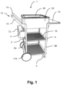
- Fig. 1
- shows a side view of a beverage serving trolley according to a first embodiment,
- Fig. 2
- shows a partly exploded view of the beverage serving trolley shown in
Fig. 1 , - Fig. 3
- shows a side view of a beverage serving trolley according to a second embodiment,
- Fig. 4
- shows another side view of the beverage serving trolley shown in
Fig. 3 , - Fig. 5
- shows a side view of a beverage serving trolley according to a third embodiment,
- Fig. 6
- shows a perspective view on constructional details that may be realized in a beverage serving trolley according to an embodiment and which are realized in the beverage serving trolley as shown in
Fig. 5 , - Fig. 7
- shows a top view on constructional details that may be realized in a beverage serving trolley according to an embodiment and which are realized in the beverage serving trolleys as shown in
Figs. 3 and5 , - Fig. 8
- shows a top view on constructional details that may be realized in a beverage serving trolley according to an embodiment and which are realized in the beverage serving trolley as shown in
Fig. 5 , - Fig. 9
- shows an oblique view on the top part of the beverage serving trolley as shown in
Fig. 5 , - Fig. 10
- shows a perspective view on a top plate that may be comprised by a beverage serving trolley according to an embodiment and that corresponds to the one installed in the beverage serving trolley shown in
Fig. 5 , - Fig. 11
- shows a view from below on a constructional detail that may be realized in a beverage serving trolley according to an embodiment and which are realized in the beverage serving trolleys shown in
Figs. 3 and5 , - Fig. 12
- shows an enlarged section of a perspective side view of the beverage serving trolleys as shown in
Figs. 3 and5 , - Fig. 13
- shows a perspective view on the top of a presentation basket that may be comprised by a beverage serving trolley according to an embodiment and that corresponds to the one with which the beverage serving trolleys shown in
Figs. 1 ,3 and5 are equipped, - Fig. 14
- shows a perspective view on the bottom of the presentation basket shown in
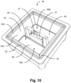
Fig. 13 , - Fig. 15
- shows a further equipped embodiment of the presentation basket shown in
Fig. 13 , - Fig. 16
- shows an exploded view of the presentation basket shown in
Fig. 13 , and - Fig. 17
- shows a perspective view of one of the symmetrical parts of the light module.
- Similar or identical elements in the various embodiments are labelled with the same reference numbers.
- Terms indicating any kind of orientation or direction like, for example, upwards, upper, downwards, lower, vertical, horizontal, sunken and lift up refer to the beverage serving trolley when standing on the ground, unless explicitly defined in a different manner. The terms "rear" and "front" are to be understood with respect to the direction of movement when the beverage serving trolley (1) is pushed by the handle (13).
- In
Figs. 1 ,3 and5 , three different embodiments of thebeverage serving trolley 1 are shown. In the first embodiment shown inFig. 1 , the beverage serving trolley includes a supporting structure 10 that is made-up ofU-shaped steel plates horizontal part 5 and twovertical parts 4. The fourvertical parts 4 of theU-shaped steel plates shelfs 16 and by the presentationbasket supporting frame 24, in order to increase the overall stability of thebeverage serving trolley 1. The shelfs are freely accessible from the sides of thebeverage serving trolley 1 and not covered by doors or the like. Thevertical parts 4 of theU-shaped steel plate 3A at the rear side of thebeverage serving trolley 1 are furthermore interconnected by thehandle 13. The term "rear side" thus refers to the moving direction of thebeverage serving trolley 1 when pushed from the side of thehandle 13. The front side of thebeverage serving trolley 1 is consequently at the opposite side of thehandle 13. - In the embodiment of
Fig. 1 , at the rearU-shaped steel plate 3A, therear wheels 11A are mounted, while at the frontU-shaped steel plate 3B, thehorizontal part 5 serves as a pedestal. Therear wheels 11A are fixed in orientation and do in particular not swivel around a vertical axis. - The
shelfs 16 are made of metal sheets and are perforated with a plurality of round holes, which reduces weight. The metal sheets are bent upwards or downwards at particular sections of their edges, which increases the stability and may in addition prevent a glass that is put on ashelf 16 from falling down. In the embodiment ofFig. 1 , the front edge of eachshelf 16 is bent downwards and both lateral edges and the rear edge of theshelfs 16 are bent upwards. - The
handle 13 is composed of thehandlebar 14 mounted between the twohandle brackets 15. Thehandle brackets 15 are made-up of steel plates as well and are flatly screwed together with thevertical parts 4 of theU-shaped steel plate 3A at the rear side. - Furthermore, between the
vertical parts 4 of the rearU-shaped steel plate 3A, an accessory is removably mounted which is thestorage box 73. Thestorage box 73 like any other appropriate accessory can simply be hung in respective hooks or protrusions (not shown) at thevertical parts 4 of bothU-shaped steel plates - A further accessory, which is however rigidly mounted to the
beverage serving trolley 1 between the frontU-shaped steel plates 3B, is thetray 74. The mounting brackets of thetray 74 are flatly screwed together with thevertical parts 4 of theU-shaped steel plate 3B, in an analogous manner as thehandle brackets 15 are mounted to the rearU-shaped steel plate 3A. - The presentation
basket supporting frame 24 has the form of a box with a square ground plate and vertical walls being sufficiently tall to accommodate thepresentation basket 40. As shown inFig. 2 in which the presentation basket is lift upwards, the presentationbasket supporting frame 24 is designed to support thepresentation basket 40 in a way that the upperouter rim 41 of thepresentation basket 40, which laterally protrudes away, rests with its supportingsurface 41A located at the underside of the protrudingrim 41 on theupper edges 25 of the presentationbasket supporting frame 24. This ensures a smooth and even closure between thepresentation basket 40 and the presentationbasket supporting frame 24. - Now, exemplary details of the
presentation basket 40 are described, by which it is also referred toFigs. 13 and14 . Thepresentation basket 40 has generally the form of a box open at the top with a square ground. It is watertight and is essentially composed of a one-piece, deep-drawn or injection-molded plastic component. Theground 51 and theinner side walls 43 of thepresentation basket 40 represent the containment for beverages and ice cubes. The wall strength provides sufficient stability, so that, when fully packed with beverages, thepresentation basket 40 can be carried by the basket handle 46 without problem. The sufficiently high wall strength furthermore has the effect of temperature isolation, so that, for example, ice cubes in thepresentation basket 40 are not melting too quickly. - The basket handle 46 is provided at the center of the
ground 51 of thepresentation basket 40 and projects upwards from there, so that thepresentation basket 40 can be carried stably and evenly by one hand. The basket handle 46 includes theelongated basket handlebar 47 and the basket handlebracket 48, which in turn is composed of twobracket columns 48A and thebracket base 48B. Between thebracket columns 48A there is provided thesaddle surface 49 on thebracket base 48B. In the present embodiment, thebasket handlebar 47 is a separate metal component that is screwed onto the top of each of thebracket columns 48A. Thebracket columns 48A and thebracket base 48B, however, form integral parts of the one-piece plastic component of thepresentation basket 40. As mentioned above, thepresentation basket 40 and the respective opening into which thepresentation basket 40 is accommodated (which in this case is established by the presentation basket supporting frame 24) are square from a top view, so that thepresentation basket 40 can be inserted in thebeverage serving trolley 1, as desired, with thebasket handlebar 47 being oriented either in or transverse to the moving direction of thebeverage serving trolley 1 when being pushed. - The
bracket columns 48A and, respectively, thebasket handlebar 47 are designed such that thebasket handlebar 47 is located at a level near, but under the level of the upper edge of thepresentation basket 40. At the upperinner rim 44 of thepresentation basket 40 there is provided thecover accommodating area 45, which is a sunken area onto which a cover (not shown) can be placed. The level up to which thebasket handlebar 47 is located is thus as high as possible, but low enough that it does not contact the cover. - At the
inner side wall 43 of thepresentation basket 40, anoutlet 42 with plug is located near theground 51 so that water in thepresentation basket 40 can be conveniently drained. - The
presentation basket 40 further includesfootstands 50, one at each corner on the underside of thepresentation basket 40. In case thepresentation basket 40 is taken out of thebeverage serving trolley 1, it can be placed with itsfootstands 50 on a table or a similar surface. - According to a further equipped embodiment of the
presentation basket 40 as shown inFig. 15 ,16 and17 , thepresentation basket 40 further includes fourremovable ice packs 52, each of which can be inserted at oneinner side wall 43. Eachice pack 52 covers the surface of the respectiveinner side wall 43. The ice packs 52 are of a plate-like shape with a ground surface corresponding to the surface of oneinner side wall 43 of thepresentation basket 40. The thickness of theice pack 52 can be selected depending on the desired cooling performance and, when vertically inserted into thepresentation basket 40, the horizontal cross-section of theice pack 52 has a trapezoidal shape so that all fourice packs 52 fit with each other when inserted (cf.Fig. 16 ). This shape and assembly also prevents theice packs 52 from falling over. - The
presentation basket 40 further includes thesheet metal tray 53 having aground 53B and fourside walls 53A, which is removably placed into thepresentation basket 40 and over the ice packs 52. Thesheet metal tray 53 in principle is a metal box with open top andupper edges 53C that are folded outwards, in order to rest on the ice packs 52. The underside of theground 53B of thesheet metal tray 53 rests on theground 51 of thepresentation basket 40 and includes acutout 53D for the basket handle 46. Thesheet metal tray 53 serves for additional stability of the ice pack assembly and due to its material barely hinders the thermal conduction. - The
presentation basket 40 further includes thelight module 56. Thelight module 56 is made-up of twosymmetrical parts symmetrical part element 57 and a flatlight emitting element 58. When inserted into thepresentation basket 40, thesymmetrical parts light module 56 are connected to each other viamagnets 57A disposed in the connectingelements 57 in the region of thesaddle surface 49 of thebracket base 48B. Each connectingelement 57 includes apower button 57B and abattery compartment 57C. Furthermore, arubber lid 57D is provided at each connectingelement 57 which covers abattery capacity indicator 57E and abattery charging port 57F. Therubber lid 57D can be easily removed by the hand in case the batteries must be charged or in case the user wants to check the battery level.Fig. 17 shows therubber lid 57D when opened. - The
light emitting element 58 covers theground 51 of thepresentation basket 40 and illuminates beverages placed into thepresentation basket 40 from below. Thelight emitting element 58 is equipped with a frostedplastic plate 59 made of acrylic glass which allows light to pass through. Thefrosted plastic plate 59 acts as a diffuser that evenly and diffusely distributes light generated by light emitting diodes located at the edges of thefrosted plastic plate 59. - Next, the second embodiment of the
beverage serving trolley 1 as shown inFigs. 3 and4 is described. Compared to thebeverage serving trolley 1 according to the first embodiment, thebeverage serving trolley 1 according to the second embodiment is laterally enclosed by a housing, adoor 17 and adrawer 18.Fig. 4 shows thebeverage serving trolley 1 withopen door 17 and thedrawer 18 pulled out. - The housing of the
beverage serving trolley 1 includesfirst side panels 19 andedge profiles 20 at an upper part of thebeverage serving trolley 1 both vertically extending over thedoor 17 and thedrawer 18, and asecond side panel 22 and an encapsulatinghousing component 23 at a lower part, i.e. under thefirst side panels 19 and edge profiles 20. These housing components are also present in thebeverage serving trolley 1 according to the third embodiment as shown inFig. 5 . In the explanation of the exact construction of the housing components, reference is also made toFigs. 6 ,7 and8 . - The edge profiles 20 essentially consist of a folded metal sheet that includes a
curved portion 20A that is wrapped around a vertical edge of thebeverage serving trolley 1 and is visible from the outside, and two inwardly bent fixingportions 20B. Both thecurved portion 20A and the fixingportions 20B vertically extend over theentire edge profile 20. The fixingportions 20B are flat and oriented in a plane perpendicular to the outside surface of thebeverage serving trolley 1 at the respective location. - The
first side panels 19 also essentially consist of a folded metal sheet. Theside panels 19 predominantly have aflat portion 19A and four inwardly bent fixingportions 19B analogue to those of the edge profiles 20. Two of the fixingportions 19B are vertically arranged and are located respectively at the two sides of theflat portion 19A, while the other two fixingportions 19B are horizontally arranged and are located respectively at the upper and lower edges of theflat portion 19A. - Each of the
first side panels 19 is connected via its vertically arranged fixingportions 19B to anedge profile 20. The fixingportions first side panel 19 and oneedge profile 20, respectively, are thereby oriented coplanar to each other and screwed together by threadedbolts 60 and nuts 61. Further, aspacer 64 is provided between theinterconnected fixing portions bolts 60 in order to provide and ensure a predeterminedvertical gap 21 between the fixingportions vertical gaps 21 are present between eachfirst side panel 19 andedge profile 20 that are connected to each other. In thevertical gaps 21, accessories can be engaged, like thestorage box 73 described in connection with the first embodiment. For this purpose, holes like the mountingbore 62B are provided at frequent distances at the fixingportions first side panel 19 andedge profile 20, respectively. - As illustrated in
Fig. 6 and shown inFig. 7 in more detail, thehousing components structure 2 which, in the embodiments shown inFigs. 3 and5 is constructed by a plurality of metalsquare tubes 6. As can be seen, one of the fixingportions 20B of theedge profile 20, one of the fixingportions 19B of thefirst side panel 19 and onesquare tube 6 are fixed together with a threadedbolt 61 that reaches through the entiresquare tube 6 and with nuts 61. At the same location, in addition, thehandle bracket 15 is mounted between the fixingportions first side panel 19 and theedge profile 20, respectively. Thehandle bracket 15 is rigidly mounted and is not intended to be removable like, for example, the above-mentioned accessories that can optionally be installed to thevertical gap 21. Here, thehandle bracket 15 also replaces thespacer 64 which would normally be present, as described above. - As shown in
Figs. 6 and8 , asquare tube 6, i.e. the supportingstructure 2 is not necessarily present at each vertical edge of thebeverage serving trolley 1. This is, for example, the case with thebeverage serving trolley 1 according to the third embodiment as shown inFig. 5 . Here, the interconnected housing components provide for enough stability, since thewine cooling cabinet 72 installed in the front part of thebeverage serving trolley 1 contributes to the stability due to its dimensions. Therefore, thesquare tubes 6 at the respective vertical edges of thebeverage serving trolley 1 can be omitted. - As mentioned above, the housing of the
beverage serving trolley 1 according to the second embodiment (Fig. 3 ) and the third embodiment (Fig. 5 ) has asecond side panel 22 and an encapsulatinghousing component 23 at a lower part, i.e. below the above describedfirst side panels 19 and edge profiles 20. These housing components are flush with thefirst side panels 19 and the edge profiles 20 and do also have a constant height all around thebeverage serving trolley 1. The encapsulatinghousing component 23 is made-up of one piece and extends over all the four corners while leaving one side free for thesecond side panel 22, which is the side where thedoor 17 anddrawer 18 are present. Thesecond side panel 22 is perforated in order to allow circulation of air. - As a further difference from the first embodiment, the
beverage serving trolley 1 according to the second and the third embodiment as shown inFigs. 3 and5 has fourwheels rear wheels 11A are rigid as those of thebeverage serving trolley 1 according to the first embodiment, thefront wheels 11B are castor wheels that can swivel about a vertical axis for a more convenient maneuvering. - The
rear wheels 11A with their outer surface are flush with the housing and, therefore, thesecond side panel 22 and the encapsulatinghousing component 23 have respective cutouts for therear wheels 11A. The distance between thefront wheels 11B to one another is shorter than that of therear wheels 11A, so that thefront wheels 11B are offset inwards compared with therear wheels 11A. - The
beverage serving trolley 1 according to the second embodiment (Fig. 3 ) and the third embodiment (Fig. 5 ) further has atop plate 30. With reference toFig. 10 which shows an extended embodiment of thetop plate 30 that is used with the third embodiment ofFig. 5 , thetop plate 30 generally has aflat surface 33, is rectangular and has arim 38 withrounded corners 32 having a curvature that corresponds to that of thecurved portion 20A of the edge profiles 20. At all sides of thebeverage serving trolley 1 including the front side and the rear side, therim 38 of thetop plate 30 is flush in a vertical direction with theflat portions 19A of thefirst side panels 19, with thecurved portions 20A of the edge profiles 20 and withdoors 17 anddrawers 18, where present. - The
top plate 30 further has acutout 34 into which thepresentation basket 40 is inserted. At thecutout edge 35, thetop plate 30 is sunken in order to provide for a smooth fit of thepresentation basket 40, which in turn rests on thesunken cutout edge 35 with its supportingsurface 41A at the underside of the upperouter rim 41. - Referring to
Fig. 12 , thetop plate 30 is connected to the horizontally arranged fixingportions 19B at the upper edge of theflat portion 19A of theside panel 19. Thespacer 64 is provided inbetween thetop plate 30 and the horizontally arranged fixingportions 19B in order to provide for and ensure a predeterminedhorizontal gap 37 between thetop plate 30 on the one hand and thefirst side panels 19 and the edge profiles 20 on the other hand. Thehorizontal gap 37 corresponds in its width with thevertical gap 21. - For the mounting of the
top plate 30, thetop plate 30 includesbolts 36 protruding down from the underside of thetop plate 30. Eachbolt 36 is fastened either only to therespective fixing portion 19B of thefirst side panel 19, only to asquare tube 6 of the supportingstructure 2 or to asquare tube 6 of the supportingstructure 2 with the fixingportion 19B of thefirst side panel 19 clamped inbetween.Fig. 11 shows the mounting details when thebolt 36 is fastened to thesquare tube 6 of the supportingstructure 2 in the case where no fixingportion 19B of thefirst side panel 19 is present. This is, for example, the case at the region of adoor 17. As can be seen inFig. 11 , thebolt 36 reaches through the mounting bore 62 A (refer toFig. 6 ) in thesquare tube 6. In order to provide access to thebolt 36 and to being able to fastening it with thenut 61, anopening 63 is provided at thesquare tube 6 which allows access with an appropriate tool (not shown) for fastening thenut 61. - While the
top plate 30 of the second embodiment shown inFig. 3 is square, thetop plate 30 of thebeverage serving trolley 1 according to the third embodiment shown inFig. 5 is broader and further includes an area besides thepresentation basket 40 on which a servingtray 70 and achopping board 71 are placed.Fig. 9 shows the upper part of thebeverage serving trolley 1 as an enlarged section with more details of thetop plate 30 andFig. 10 shows the isolatedtop plate 30. In area next to thepresentation basket 40, thetop plate 30 has a recessedportion 31 in order to hold the servingtray 70 and thechopping board 71 in place when moving thebeverage serving trolley 1. The recessedportion 31 is not subdivided and is one single square shaped recessedportion 31. The servingtray 70 and thechopping board 71 are oblong and fit next to each other in the recessedportion 31 either lengthwise or crosswise to the moving direction of thebeverage serving trolley 1. - The third embodiment of the
beverage serving trolley 1 as shown inFig. 5 is larger or, more particular, longer than the second embodiment of thebeverage serving trolley 1 as shown inFig. 3 . Thebeverage serving trolley 1 ofFig. 5 further includes thewine cooling cabinet 72 which is located below the servingtray 70 and thechopping board 71, and next to thedoor 17 and thedrawer 18. Thewine cooling cabinet 72 works electrically and the respective power cable (not shown) can be stowed during non-use below thewine cooling cabinet 72 and out of sight. Furthermore, thebeverage serving trolley 1 includes a battery (not shown) for thewine cooling cabinet 72 which is either integrated into thewine cooling cabinet 72 itself or provided separately below thewine cooling cabinet 72. -
- 1
- Beverage serving trolley
- 2
- supporting structure
- 3A
- rear U-shaped steel plate
- 3B
- front U-shaped steel plate
- 4
- vertical part of U-shaped steel plate
- 5
- horizontal part of U-shaped steel plate
- 6
- square tube
- 11A
- rear wheel
- 11B
- front wheel
- 13
- handle
- 14
- handlebar
- 15
- handle bracket
- 16
- shelf
- 17
- door
- 18
- drawer
- 19
- first side panel
- 19A
- flat portion
- 19B
- fixing portion of first side panel
- 20
- edge profile
- 20A
- curved portion
- 20B
- fixing portion of edge profile
- 21
- vertical gap
- 22
- second side panel
- 23
- encapsulating housing component
- 24
- presentation basket supporting frame
- 25
- upper edge of supporting frame
- 30
- top plate
- 31
- recessed portion
- 32
- rounded corner
- 33
- flat surface of top plate
- 34
- cutout
- 35
- cutout edge
- 36
- bolt
- 37
- horizontal gap
- 38
- rim of top plate
- 40
- presentation basket
- 41
- upper outer rim of presentation basket
- 41A
- supporting surface
- 42
- outlet
- 43
- inner side wall
- 44
- upper inner rim
- 45
- cover accommodating area
- 46
- basket handle
- 47
- basket handlebar
- 48
- basket handle bracket
- 48A
- bracket column
- 48B
- bracket base
- 49
- saddle surface
- 50
- footstand
- 51
- ground inside the presentation basket
- 52
- ice pack
- 53
- sheet metal tray
- 53A
- side wall of sheet metal tray
- 53B
- ground of sheet metal tray
- 53C
- upper edge of sheet metal tray
- 53D
- cutout of sheet metal tray
- 56
- light module
- 56A, B
- symmetrical part of light module
- 57
- connecting element
- 57A
- magnet
- 57B
- power button
- 57C
- battery compartment
- 57D
- rubber lid
- 57E
- battery capacity indicator
- 57F
- battery charging port
- 58
- light emitting element
- 59
- frosted plastic plate
- 60
- threaded bolt
- 61
- nut
- 62A
- mounting bore at square tube
- 62B
- mounting bore at fixing portion of side panel
- 63
- opening
- 64
- spacer
- 70
- serving tray
- 71
- chopping board
- 72
- wine cooling cabinet
- 73
- storage box
- 74
- board
Claims (13)
- Beverage serving trolley (1) comprising a supporting structure (2), at least one wheel (11A, 11B), a presentation basket (40) comprising a basket handle (46) and being configured to receive beverage bottles and ice cubes, and an outer housing, wherein the outer housing includes at least one first side panel (19),
characterized in that
the outer housing includes at least one edge profile (20) and the at least one first side panel (19) and the at least one edge profile (20) cover at least in part at least one side and at least one vertical edge, respectively, of the beverage serving trolley (1), wherein both the at least one first side panel (19) and the at least one edge profile (20) have the same vertical extension and are mounted to the beverage serving trolley (1) in a way that adjacent first side panels (19) and edge profiles (20) are connected flush with each other at their respective vertical edges with a distance, thus forming a vertical gap (21) of a predetermined width between each other. - Beverage serving trolley (1) according to claim 1, characterized in that the at least one first side panel (19) is a folded metal sheet including a flat portion (19A) and at least two fixing portions (19B), wherein the flat portion (19A) covers at least part of a side of the beverage serving trolley (1) and at least one of the fixing portions (19B) of the at least one first side panel (19) is provided at each vertical edge of the flat portion (19A) and is folded inwardly, and in that the at least one edge profile (20) is a folded metal sheet including a curved portion (20A) and at least two fixing portions (20B), wherein the curved portion (20A) covers at least part of a vertical edge of the beverage serving trolley (1), and at least one of the fixing portions (20B) of the at least one edge profile (20) is provided at each vertical edge of the curved portion (20A) and is folded inwardly.
- Beverage serving trolley (1) according to claim 2, characterized in that adjacent fixing portions (19B, 20B) of the at least one first side panel (19) and the at least one edge profile (20) are coplanar to each other and are connected together with a spacer (64) located between each other, in order to form the vertical gap (21).
- Beverage serving trolley (1) according to claim 3, characterized in that at least one pair of interconnected fixing portions (19B, 20B) is additionally connected to the supporting structure (2).
- Beverage serving trolley (1) according to claim 4, characterized in that the at least one first side panel (19) includes more than two fixing portions (19B), wherein at least one of the fixing portions (19B) is provided at an upper horizontal edge of the flat portion (19A) and is folded inwardly, and at least one of the fixing portions (19B) is provided at a lower horizontal edge of the flat portion (19A) and is folded inwardly.
- Beverage serving trolley (1) according to claim 5, characterized in that the beverage serving trolley (1) further comprises a horizontally arranged top plate (30) having a flat surface (33), wherein the fixing portions (19B) at the upper horizontal edge of the flat portion (19A) of the at least one first side panel (19) are coplanar with the flat surface (33) of the top plate (30) and are connected to the top plate (30) with a spacer (64) inbetween, in order to form a horizontal gap (37) of a predetermined width between the lower edge of the top plate (30) and the upper horizontal edge of the flat portion (19A).
- Beverage serving trolley (1) according to claim 6, characterized in that the outer housing further includes a second side panel (22) and an encapsulating housing component (23) both having the same vertical extension and being arranged below the at least one first side panel (19) and the at least one edge profile (20).
- Beverage serving trolley (1) according to claim 7, characterized in that the second side panel (22) and the encapsulating housing component (23) are connected to each other at both of their vertical edges, thereby horizontally surrounding the complete circumference of the beverage serving trolley (1).
- Beverage serving trolley (1) according to claim 8, characterized in that the encapsulating housing component (23) is connected to the fixing portion (19B) at the lower edge of the flat portion (19A) of the at least one first side panel (19).
- Beverage serving trolley (1) according to claim 9, characterized in that the encapsulating housing component (23) is flush in a vertical direction with the flat portion (19A) of the at least one first side panel (19) and with the curved portion (20A) of the at least one edge profile (20) that are arranged above the encapsulating housing component (23).
- Beverage serving trolley (1) according to claim 10, characterized in that the encapsulating housing component (23) circumferentially extends over four vertical edges and three sides of the beverage serving trolley (1), while the second side panel (22) extends over a fourth side of the beverage serving trolley (1).
- Beverage serving trolley (1) according to claim 7,
characterized in that the second side panel (22) is perforated in order to allow circulation of air. - Beverage serving trolley (1) according to any one of the preceding claims, characterized in that the beverage serving trolley (1) further comprises a handle (13) for moving the beverage serving trolley (1).
Applications Claiming Priority (2)
| Application Number | Priority Date | Filing Date | Title |
|---|---|---|---|
| DE102020200831.0A DE102020200831B4 (en) | 2020-01-23 | 2020-01-23 | BEVERAGE TROLLEY |
| PCT/EP2021/051247 WO2021148493A1 (en) | 2020-01-23 | 2021-01-21 | Beverage serving trolley |
Publications (2)
| Publication Number | Publication Date |
|---|---|
| EP4077099A1 EP4077099A1 (en) | 2022-10-26 |
| EP4077099B1 true EP4077099B1 (en) | 2024-05-22 |
Family
ID=74215940
Family Applications (1)
| Application Number | Title | Priority Date | Filing Date |
|---|---|---|---|
| EP21701483.6A Active EP4077099B1 (en) | 2020-01-23 | 2021-01-21 | Beverage serving trolley |
Country Status (6)
| Country | Link |
|---|---|
| US (2) | US12263875B2 (en) |
| EP (1) | EP4077099B1 (en) |
| CN (1) | CN114929552A (en) |
| AU (1) | AU2021209826A1 (en) |
| DE (1) | DE102020200831B4 (en) |
| WO (1) | WO2021148493A1 (en) |
Families Citing this family (6)
| Publication number | Priority date | Publication date | Assignee | Title |
|---|---|---|---|---|
| DE102020200829A1 (en) | 2020-01-23 | 2021-07-29 | Dometic Sweden Ab | BEVERAGE SERVING TROLLEY WITH IMPROVED PRESENTATION OF BEVERAGES |
| DE102020200825A1 (en) | 2020-01-23 | 2021-07-29 | Dometic Sweden Ab | BEVERAGE SERVING TROLLEY |
| DE102020200831B4 (en) | 2020-01-23 | 2023-11-30 | Dometic Sweden Ab | BEVERAGE TROLLEY |
| USD1007091S1 (en) * | 2021-02-10 | 2023-12-05 | Intermetro Industries Corporation | Closed case cart |
| US20230219607A1 (en) * | 2021-03-04 | 2023-07-13 | Reflo, Inc. | Outdoor Discovery Cart |
| TWI858403B (en) * | 2022-10-05 | 2024-10-11 | 彩經開發有限公司 | Multi-function mobile cooking table |
Family Cites Families (100)
| Publication number | Priority date | Publication date | Assignee | Title |
|---|---|---|---|---|
| US1948937A (en) | 1929-11-19 | 1934-02-27 | Jones Mcduffee & Stratton Corp | Food servicer |
| US1985412A (en) * | 1934-01-29 | 1934-12-25 | Brunswick Balke Collender Co | Portable bar |
| US2116312A (en) | 1935-04-06 | 1938-05-03 | Hollett George Bonnell | Wheeled truck |
| US2728485A (en) | 1953-04-13 | 1955-12-27 | Atlanta Paper Company | Bottle carrier |
| DE1788154U (en) | 1959-02-25 | 1959-05-06 | Metallwarenfabrik Rudolf Loh G | HOUSEHOLD CARS. |
| US3463353A (en) | 1968-05-21 | 1969-08-26 | Peebles David M | Nesting container assembly |
| US3874531A (en) * | 1974-03-21 | 1975-04-01 | William D Mayo | Cart and vehicular carrying system for the cart |
| DE2643859A1 (en) * | 1976-09-29 | 1978-03-30 | Lermer App Gmbh | ROLLABLE CONTAINER WHICH IS IN A PARALLEL PIPED SHAPE, ESPECIALLY FOR USE IN AIRCRAFT |
| USD298079S (en) | 1985-09-30 | 1988-10-11 | Chatham Richard W | Organizer tray for plumbers |
| GB2184697A (en) | 1985-12-31 | 1987-07-01 | Rydal Precision Engineering Co | Foldable trolley base |
| US4875696A (en) | 1986-08-26 | 1989-10-24 | Intermetro Industries Corporation | Caster direction-locking mechanism for mobile cart |
| US4923202A (en) | 1986-09-29 | 1990-05-08 | Geerpres, Inc. | Utility cart |
| US4702402A (en) * | 1986-10-17 | 1987-10-27 | Ferri Vincent J | Product coupon container attachable to shopping cart |
| USD307967S (en) | 1987-07-20 | 1990-05-15 | Flambeau Corporation | Tool box tray |
| USD329135S (en) | 1988-05-23 | 1992-09-08 | Rubbermaid Incorporated | Tool caddy |
| USD327562S (en) | 1990-03-13 | 1992-06-30 | Rubbermain Incorporated | Tool carrying tray |
| NL9301930A (en) * | 1993-11-05 | 1995-06-01 | Albertus Franciscus Vorstenbos | Box-shaped transport container. |
| USD364039S (en) | 1994-08-08 | 1995-11-14 | Sterilite Corporation | Caddy with handle |
| US5716116A (en) * | 1995-04-21 | 1998-02-10 | Metro Industries, Inc. | Utility cabinet and modular storage and support assembly using the utility cabinet |
| USD386616S (en) | 1996-05-13 | 1997-11-25 | Fred Nimer | Molded utility basket |
| US5848695A (en) | 1997-08-07 | 1998-12-15 | Riverwood International Corporation | Side-loading basket carrier |
| USD424773S (en) * | 1998-03-03 | 2000-05-09 | S. Berendsen Ab | Transport carriage |
| US6193247B1 (en) * | 1998-03-05 | 2001-02-27 | O. Ames Co. | Portable stackable wagon assembly |
| BE1012244A3 (en) | 1998-10-22 | 2000-08-01 | D W Plastics Nv | Crate of plastic, provided with at least a handle. |
| IT1321048B1 (en) | 2000-11-07 | 2003-12-30 | Bridgestone Firestone Tech | METHOD AND DEVICE FOR THE CREATION OF A TWO-COMPONENT LAYER OF A TIRE. |
| US6827357B2 (en) | 2001-02-09 | 2004-12-07 | Akro-Mils, A Division Of Myers Industries Company | Janitorial cart |
| US6758482B2 (en) | 2001-10-01 | 2004-07-06 | Harper Trucks, Inc. | Multipurpose storage and transport cart |
| US6612127B2 (en) | 2001-12-27 | 2003-09-02 | Jesse K. Simmons | Portable refrigeration table with elevating and supporting dividers |
| USD468881S1 (en) | 2002-03-06 | 2003-01-14 | Bruce W. Cox | Cart |
| US20030201619A1 (en) | 2002-04-29 | 2003-10-30 | Jimmy Teng | Universal transportation wheel kit |
| USD484011S1 (en) | 2003-01-07 | 2003-12-23 | Progressive Speciality Glass Co., Inc. | Beverage carrier |
| CA108235S (en) * | 2004-09-03 | 2008-05-15 | Adaptaide Inc | Chariot |
| CN101128353A (en) | 2005-01-21 | 2008-02-20 | 勒博美商业产品有限责任公司 | maintenance car |
| USD537251S1 (en) | 2005-09-08 | 2007-02-27 | Sandra Musgrove | Carrier including securing member |
| DE102005044984B3 (en) | 2005-09-20 | 2007-01-25 | Carl Freudenberg Kg | Trolley for cleaning tasks has an extendable frame made from combinable elements with releasable connections and U-shaped parts |
| US7536868B1 (en) | 2005-12-22 | 2009-05-26 | Ward Richard W | Temperature controlled cart |
| USD547920S1 (en) * | 2006-04-03 | 2007-07-31 | Bretford Manufacturing, Inc. | Computer cart |
| US20070267832A1 (en) * | 2006-05-16 | 2007-11-22 | Evgueni Denissov | Cleaning cart |
| ATE430709T1 (en) * | 2007-03-07 | 2009-05-15 | Wittur Holding Gmbh | SELF-SUPPORTING CAR |
| US7891678B2 (en) | 2008-03-18 | 2011-02-22 | Suncast Technologies, Llc | Wagon with removal bins |
| GB0808858D0 (en) | 2008-05-15 | 2008-06-25 | Young Ronald A | Combination of a trolley for carrying cleaning materials and bucket structure |
| US20100066045A1 (en) * | 2008-09-15 | 2010-03-18 | Rubbermaid Commercial Products, Llc | Cart |
| US8696028B2 (en) | 2009-01-30 | 2014-04-15 | Frankie Nelson | Janitorial container with segmented, drainable utility compartments |
| US8544141B1 (en) | 2009-03-04 | 2013-10-01 | Kaivac, Inc. | Cleaning cart systems |
| EP2676891A3 (en) | 2009-03-31 | 2014-09-24 | D W Plastics N.V. | Bottle crate with central carrier handle, central carrier handle and method of manufacturing a bottle crate with central carrier handle. |
| US8550477B2 (en) * | 2009-05-14 | 2013-10-08 | Vickie Bennett | Spa cart system and method |
| US20110232102A1 (en) | 2010-03-25 | 2011-09-29 | Larry Holmes | Serving Placemat and Food Service Article |
| US9089210B2 (en) | 2010-05-10 | 2015-07-28 | Christiaan Kool | Service trolley |
| US8556740B1 (en) * | 2010-12-21 | 2013-10-15 | Darla G. Schneider | Portable sandbox |
| KR20120006719U (en) | 2011-03-22 | 2012-10-04 | 이효복 | Table with store space for basket |
| USD649786S1 (en) | 2011-08-11 | 2011-12-06 | Target Brands, Inc. | Caddy |
| USD690939S1 (en) | 2011-11-10 | 2013-10-08 | Thomas R. Lintz | Caddy |
| AU341137S (en) * | 2011-12-14 | 2012-02-23 | Oates Pty Ltd E D | Janitor's cart (1) |
| USD671703S1 (en) | 2012-02-02 | 2012-11-27 | Bretford Manufacturing Inc. | Computer cart |
| US8636169B2 (en) | 2012-02-13 | 2014-01-28 | Casabella Holdings, Llc | Caddy and removable mini caddy tote |
| US9139331B2 (en) * | 2012-02-29 | 2015-09-22 | Mark Tavolino | Storage system |
| USD688589S1 (en) | 2012-09-04 | 2013-08-27 | Ames True Temper, Inc. | Plant caddy |
| USD690109S1 (en) | 2012-11-29 | 2013-09-24 | Josh Shupp | Carrier for transporting alcoholic beverage bottles |
| US20140238979A1 (en) * | 2013-02-27 | 2014-08-28 | Jen Mei Tai | Modular Shipping Container |
| US8924258B2 (en) * | 2013-03-13 | 2014-12-30 | Target Brands, Inc. | Mobile point-of-sale |
| US9446847B2 (en) | 2013-04-29 | 2016-09-20 | The Boeing Company | Vertically mounted dry ice cooling compartment applied to a galley cart for temperature gradient reduction |
| USD734913S1 (en) | 2014-01-03 | 2015-07-21 | Unger Marketing International, Llc | Cleaning cart |
| US20150097001A1 (en) | 2013-10-09 | 2015-04-09 | The Coca-Cola Company | Mobile beverage cart |
| US20150284018A1 (en) * | 2014-04-07 | 2015-10-08 | Steri Sc International Llc | Containment device and transport system for reusable medical device sterilization, storage, and transport |
| US9283975B2 (en) | 2014-05-30 | 2016-03-15 | Unarco Industries Llc | Modular cart |
| US9205951B1 (en) | 2014-07-24 | 2015-12-08 | Josephine E. Roman | All-in-one stackable bulletin board caddy |
| US9481386B2 (en) | 2014-10-28 | 2016-11-01 | Target Brands, Inc. | Mobile cart |
| US9925998B2 (en) | 2014-12-17 | 2018-03-27 | Amazon Technologies, Inc. | Consolidated pick and pack for outbound fulfillment |
| WO2016118514A1 (en) | 2015-01-20 | 2016-07-28 | Unrath Nancy K N | Market trolley |
| US9315204B1 (en) * | 2015-01-21 | 2016-04-19 | Christopher Birrell | Recycling cart |
| US10106182B2 (en) | 2015-12-10 | 2018-10-23 | C5 Enterprises | Foldable cart system and method |
| USD783287S1 (en) | 2015-12-22 | 2017-04-11 | Thirty-One Gifts Llc | Convertible organizer |
| USD789690S1 (en) | 2016-01-04 | 2017-06-20 | Deflecto, LLC | Storage container |
| US9623890B1 (en) | 2016-04-18 | 2017-04-18 | Brian Horowitz | Folding wagon having a cooler and a removable table connected thereto |
| CA3216027C (en) | 2016-05-13 | 2024-06-18 | Suncast Technologies, Llc | Bumper assembly for a housekeeping cart |
| AU201616042S (en) | 2016-05-20 | 2017-01-18 | Unilever Plc | Caddy for presenting bottles |
| US20190023298A1 (en) * | 2016-05-27 | 2019-01-24 | Alexander Louis Carzola | Multipurpose Mobile Utility Lifting Ergonomic Cart |
| US9877577B2 (en) | 2016-05-31 | 2018-01-30 | William G. Knighton | Storage and serving cart |
| US10029721B2 (en) * | 2016-06-24 | 2018-07-24 | Jeffrey K. Jackson | Hydration cart |
| US10136725B2 (en) | 2016-08-26 | 2018-11-27 | Plank and Hide | Outdoor convertible table-like furniture with multiple levels |
| USD812377S1 (en) | 2016-10-05 | 2018-03-13 | The Stanley Works Israel Ltd | Open top storage |
| USD838482S1 (en) | 2017-01-22 | 2019-01-22 | Chrisitan Pistauer | Mobile desk organizer |
| US9989299B1 (en) | 2017-04-21 | 2018-06-05 | Robert Ballard | Cooler |
| US10321778B2 (en) * | 2017-06-02 | 2019-06-18 | Cambro Manufacturing Company | Adjustable dish caddy |
| US10427702B2 (en) * | 2017-10-16 | 2019-10-01 | Suncast Technologies, Llc | Modular utility cart with removably positionable bins and drawer |
| USD863764S1 (en) | 2018-06-06 | 2019-10-22 | Mr. Bar-B-Q Products Llc | Caddy |
| US10463180B1 (en) | 2018-07-06 | 2019-11-05 | Brian Donnelly | Candle decks and covers for cakes and cupcakes |
| US10611391B1 (en) * | 2018-10-05 | 2020-04-07 | Corindus, Inc. | Mobile support and storage system for a medical device |
| USD876835S1 (en) | 2018-11-30 | 2020-03-03 | The Libman Company | Caddy |
| US11332177B2 (en) * | 2019-02-01 | 2022-05-17 | Ergotron, Inc. | Charging and storage cart with accessory mounting system and method |
| USD923903S1 (en) | 2019-06-03 | 2021-06-29 | Tomi Environmental Solutions, Inc. | Decontamination cart |
| DE102020200831B4 (en) | 2020-01-23 | 2023-11-30 | Dometic Sweden Ab | BEVERAGE TROLLEY |
| DE102020200830B4 (en) | 2020-01-23 | 2023-11-30 | Dometic Sweden Ab | BEVERAGE TROLLEY |
| USD939214S1 (en) | 2020-01-23 | 2021-12-28 | Dometic Sweden Ab | Basket |
| DE102020200825A1 (en) | 2020-01-23 | 2021-07-29 | Dometic Sweden Ab | BEVERAGE SERVING TROLLEY |
| USD968047S1 (en) | 2020-01-23 | 2022-10-25 | Dometic Sweden Ab | Beverage cart |
| DE102020200829A1 (en) | 2020-01-23 | 2021-07-29 | Dometic Sweden Ab | BEVERAGE SERVING TROLLEY WITH IMPROVED PRESENTATION OF BEVERAGES |
| US11814094B2 (en) * | 2020-05-05 | 2023-11-14 | Barmobile, LLC | Mobile serving device and method |
| USD895292S1 (en) | 2020-06-04 | 2020-09-08 | Safe Products LLC | Protective liner for shopping basket |
| KR102741193B1 (en) * | 2022-10-05 | 2024-12-11 | (주)코리아환경산업 | Mobile cleaning device with sterilization function |
-
2020
- 2020-01-23 DE DE102020200831.0A patent/DE102020200831B4/en active Active
-
2021
- 2021-01-21 AU AU2021209826A patent/AU2021209826A1/en not_active Abandoned
- 2021-01-21 EP EP21701483.6A patent/EP4077099B1/en active Active
- 2021-01-21 WO PCT/EP2021/051247 patent/WO2021148493A1/en not_active Ceased
- 2021-01-21 CN CN202180006803.6A patent/CN114929552A/en active Pending
- 2021-01-21 US US17/794,591 patent/US12263875B2/en active Active
-
2025
- 2025-03-25 US US19/089,729 patent/US20250222967A1/en active Pending
Also Published As
| Publication number | Publication date |
|---|---|
| CN114929552A (en) | 2022-08-19 |
| WO2021148493A1 (en) | 2021-07-29 |
| EP4077099A1 (en) | 2022-10-26 |
| DE102020200831A1 (en) | 2021-07-29 |
| DE102020200831B4 (en) | 2023-11-30 |
| US12263875B2 (en) | 2025-04-01 |
| US20230114863A1 (en) | 2023-04-13 |
| US20250222967A1 (en) | 2025-07-10 |
| AU2021209826A1 (en) | 2022-06-02 |
Similar Documents
| Publication | Publication Date | Title |
|---|---|---|
| US12263875B2 (en) | Beverage serving trolley | |
| EP4037953B1 (en) | Beverage serving trolley | |
| EP4037952B1 (en) | Beverage serving trolley with beverage presentation | |
| EP4041612B1 (en) | Beverage serving trolley | |
| US4123128A (en) | Portable pie case | |
| US5743438A (en) | Under shelf rack for water container | |
| EP2745062B1 (en) | Delivery container for temperature sensitive goods | |
| US10421407B2 (en) | Trunk mounted storage rack for sport utility vehicles | |
| US20030209505A1 (en) | Display shelf for stackable products | |
| US7334853B2 (en) | Refrigerator door beverage storage module | |
| US20060168992A1 (en) | Cooler with individual container pockets | |
| US5588724A (en) | Camp kitchen cabinet | |
| US20090121597A1 (en) | Food display with shelving system | |
| KR101487627B1 (en) | Hot and cool food service cart | |
| EP2927148B1 (en) | Multifunctional shelf of a refrigerator cavity, and refrigerator provided with such shelf | |
| AU6121500A (en) | Refrigerator storage tray | |
| US7703865B2 (en) | Storage compartment for a refrigeration device | |
| CA2568759C (en) | Chime for an alcohol containing cask | |
| CN218936794U (en) | Storage container device for household refrigeration appliance and household refrigeration appliance | |
| JPH0515778Y2 (en) | ||
| CN112254418A (en) | Protection component for refrigerator interior decoration and refrigerator | |
| JP2002253399A (en) | Refrigerated displaying apparatus |
Legal Events
| Date | Code | Title | Description |
|---|---|---|---|
| STAA | Information on the status of an ep patent application or granted ep patent |
Free format text: STATUS: UNKNOWN |
|
| STAA | Information on the status of an ep patent application or granted ep patent |
Free format text: STATUS: THE INTERNATIONAL PUBLICATION HAS BEEN MADE |
|
| PUAI | Public reference made under article 153(3) epc to a published international application that has entered the european phase |
Free format text: ORIGINAL CODE: 0009012 |
|
| STAA | Information on the status of an ep patent application or granted ep patent |
Free format text: STATUS: REQUEST FOR EXAMINATION WAS MADE |
|
| 17P | Request for examination filed |
Effective date: 20220720 |
|
| AK | Designated contracting states |
Kind code of ref document: A1 Designated state(s): AL AT BE BG CH CY CZ DE DK EE ES FI FR GB GR HR HU IE IS IT LI LT LU LV MC MK MT NL NO PL PT RO RS SE SI SK SM TR |
|
| DAV | Request for validation of the european patent (deleted) | ||
| DAX | Request for extension of the european patent (deleted) | ||
| P01 | Opt-out of the competence of the unified patent court (upc) registered |
Effective date: 20230526 |
|
| GRAP | Despatch of communication of intention to grant a patent |
Free format text: ORIGINAL CODE: EPIDOSNIGR1 |
|
| STAA | Information on the status of an ep patent application or granted ep patent |
Free format text: STATUS: GRANT OF PATENT IS INTENDED |
|
| INTG | Intention to grant announced |
Effective date: 20240125 |
|
| GRAS | Grant fee paid |
Free format text: ORIGINAL CODE: EPIDOSNIGR3 |
|
| GRAA | (expected) grant |
Free format text: ORIGINAL CODE: 0009210 |
|
| STAA | Information on the status of an ep patent application or granted ep patent |
Free format text: STATUS: THE PATENT HAS BEEN GRANTED |
|
| AK | Designated contracting states |
Kind code of ref document: B1 Designated state(s): AL AT BE BG CH CY CZ DE DK EE ES FI FR GB GR HR HU IE IS IT LI LT LU LV MC MK MT NL NO PL PT RO RS SE SI SK SM TR |
|
| REG | Reference to a national code |
Ref country code: GB Ref legal event code: FG4D |
|
| REG | Reference to a national code |
Ref country code: CH Ref legal event code: EP |
|
| REG | Reference to a national code |
Ref country code: DE Ref legal event code: R096 Ref document number: 602021013552 Country of ref document: DE |
|
| REG | Reference to a national code |
Ref country code: IE Ref legal event code: FG4D |
|
| REG | Reference to a national code |
Ref country code: LT Ref legal event code: MG9D |
|
| REG | Reference to a national code |
Ref country code: NL Ref legal event code: MP Effective date: 20240522 |
|
| PG25 | Lapsed in a contracting state [announced via postgrant information from national office to epo] |
Ref country code: IS Free format text: LAPSE BECAUSE OF FAILURE TO SUBMIT A TRANSLATION OF THE DESCRIPTION OR TO PAY THE FEE WITHIN THE PRESCRIBED TIME-LIMIT Effective date: 20240922 |
|
| PG25 | Lapsed in a contracting state [announced via postgrant information from national office to epo] |
Ref country code: BG Free format text: LAPSE BECAUSE OF FAILURE TO SUBMIT A TRANSLATION OF THE DESCRIPTION OR TO PAY THE FEE WITHIN THE PRESCRIBED TIME-LIMIT Effective date: 20240522 |
|
| PG25 | Lapsed in a contracting state [announced via postgrant information from national office to epo] |
Ref country code: FI Free format text: LAPSE BECAUSE OF FAILURE TO SUBMIT A TRANSLATION OF THE DESCRIPTION OR TO PAY THE FEE WITHIN THE PRESCRIBED TIME-LIMIT Effective date: 20240522 Ref country code: HR Free format text: LAPSE BECAUSE OF FAILURE TO SUBMIT A TRANSLATION OF THE DESCRIPTION OR TO PAY THE FEE WITHIN THE PRESCRIBED TIME-LIMIT Effective date: 20240522 |
|
| PG25 | Lapsed in a contracting state [announced via postgrant information from national office to epo] |
Ref country code: GR Free format text: LAPSE BECAUSE OF FAILURE TO SUBMIT A TRANSLATION OF THE DESCRIPTION OR TO PAY THE FEE WITHIN THE PRESCRIBED TIME-LIMIT Effective date: 20240823 |
|
| PG25 | Lapsed in a contracting state [announced via postgrant information from national office to epo] |
Ref country code: PT Free format text: LAPSE BECAUSE OF FAILURE TO SUBMIT A TRANSLATION OF THE DESCRIPTION OR TO PAY THE FEE WITHIN THE PRESCRIBED TIME-LIMIT Effective date: 20240923 |
|
| REG | Reference to a national code |
Ref country code: AT Ref legal event code: MK05 Ref document number: 1688552 Country of ref document: AT Kind code of ref document: T Effective date: 20240522 |
|
| PG25 | Lapsed in a contracting state [announced via postgrant information from national office to epo] |
Ref country code: NL Free format text: LAPSE BECAUSE OF FAILURE TO SUBMIT A TRANSLATION OF THE DESCRIPTION OR TO PAY THE FEE WITHIN THE PRESCRIBED TIME-LIMIT Effective date: 20240522 |
|
| PG25 | Lapsed in a contracting state [announced via postgrant information from national office to epo] |
Ref country code: ES Free format text: LAPSE BECAUSE OF FAILURE TO SUBMIT A TRANSLATION OF THE DESCRIPTION OR TO PAY THE FEE WITHIN THE PRESCRIBED TIME-LIMIT Effective date: 20240522 |
|
| PG25 | Lapsed in a contracting state [announced via postgrant information from national office to epo] |
Ref country code: AT Free format text: LAPSE BECAUSE OF FAILURE TO SUBMIT A TRANSLATION OF THE DESCRIPTION OR TO PAY THE FEE WITHIN THE PRESCRIBED TIME-LIMIT Effective date: 20240522 |
|
| PG25 | Lapsed in a contracting state [announced via postgrant information from national office to epo] |
Ref country code: PL Free format text: LAPSE BECAUSE OF FAILURE TO SUBMIT A TRANSLATION OF THE DESCRIPTION OR TO PAY THE FEE WITHIN THE PRESCRIBED TIME-LIMIT Effective date: 20240522 |
|
| PG25 | Lapsed in a contracting state [announced via postgrant information from national office to epo] |
Ref country code: LV Free format text: LAPSE BECAUSE OF FAILURE TO SUBMIT A TRANSLATION OF THE DESCRIPTION OR TO PAY THE FEE WITHIN THE PRESCRIBED TIME-LIMIT Effective date: 20240522 |
|
| PG25 | Lapsed in a contracting state [announced via postgrant information from national office to epo] |
Ref country code: PT Free format text: LAPSE BECAUSE OF FAILURE TO SUBMIT A TRANSLATION OF THE DESCRIPTION OR TO PAY THE FEE WITHIN THE PRESCRIBED TIME-LIMIT Effective date: 20240923 Ref country code: PL Free format text: LAPSE BECAUSE OF FAILURE TO SUBMIT A TRANSLATION OF THE DESCRIPTION OR TO PAY THE FEE WITHIN THE PRESCRIBED TIME-LIMIT Effective date: 20240522 Ref country code: NO Free format text: LAPSE BECAUSE OF FAILURE TO SUBMIT A TRANSLATION OF THE DESCRIPTION OR TO PAY THE FEE WITHIN THE PRESCRIBED TIME-LIMIT Effective date: 20240822 Ref country code: NL Free format text: LAPSE BECAUSE OF FAILURE TO SUBMIT A TRANSLATION OF THE DESCRIPTION OR TO PAY THE FEE WITHIN THE PRESCRIBED TIME-LIMIT Effective date: 20240522 Ref country code: LV Free format text: LAPSE BECAUSE OF FAILURE TO SUBMIT A TRANSLATION OF THE DESCRIPTION OR TO PAY THE FEE WITHIN THE PRESCRIBED TIME-LIMIT Effective date: 20240522 Ref country code: IS Free format text: LAPSE BECAUSE OF FAILURE TO SUBMIT A TRANSLATION OF THE DESCRIPTION OR TO PAY THE FEE WITHIN THE PRESCRIBED TIME-LIMIT Effective date: 20240922 Ref country code: HR Free format text: LAPSE BECAUSE OF FAILURE TO SUBMIT A TRANSLATION OF THE DESCRIPTION OR TO PAY THE FEE WITHIN THE PRESCRIBED TIME-LIMIT Effective date: 20240522 Ref country code: GR Free format text: LAPSE BECAUSE OF FAILURE TO SUBMIT A TRANSLATION OF THE DESCRIPTION OR TO PAY THE FEE WITHIN THE PRESCRIBED TIME-LIMIT Effective date: 20240823 Ref country code: FI Free format text: LAPSE BECAUSE OF FAILURE TO SUBMIT A TRANSLATION OF THE DESCRIPTION OR TO PAY THE FEE WITHIN THE PRESCRIBED TIME-LIMIT Effective date: 20240522 Ref country code: ES Free format text: LAPSE BECAUSE OF FAILURE TO SUBMIT A TRANSLATION OF THE DESCRIPTION OR TO PAY THE FEE WITHIN THE PRESCRIBED TIME-LIMIT Effective date: 20240522 Ref country code: BG Free format text: LAPSE BECAUSE OF FAILURE TO SUBMIT A TRANSLATION OF THE DESCRIPTION OR TO PAY THE FEE WITHIN THE PRESCRIBED TIME-LIMIT Effective date: 20240522 Ref country code: AT Free format text: LAPSE BECAUSE OF FAILURE TO SUBMIT A TRANSLATION OF THE DESCRIPTION OR TO PAY THE FEE WITHIN THE PRESCRIBED TIME-LIMIT Effective date: 20240522 Ref country code: RS Free format text: LAPSE BECAUSE OF FAILURE TO SUBMIT A TRANSLATION OF THE DESCRIPTION OR TO PAY THE FEE WITHIN THE PRESCRIBED TIME-LIMIT Effective date: 20240822 |
|
| PG25 | Lapsed in a contracting state [announced via postgrant information from national office to epo] |
Ref country code: DK Free format text: LAPSE BECAUSE OF FAILURE TO SUBMIT A TRANSLATION OF THE DESCRIPTION OR TO PAY THE FEE WITHIN THE PRESCRIBED TIME-LIMIT Effective date: 20240522 |
|
| PG25 | Lapsed in a contracting state [announced via postgrant information from national office to epo] |
Ref country code: EE Free format text: LAPSE BECAUSE OF FAILURE TO SUBMIT A TRANSLATION OF THE DESCRIPTION OR TO PAY THE FEE WITHIN THE PRESCRIBED TIME-LIMIT Effective date: 20240522 |
|
| PG25 | Lapsed in a contracting state [announced via postgrant information from national office to epo] |
Ref country code: CZ Free format text: LAPSE BECAUSE OF FAILURE TO SUBMIT A TRANSLATION OF THE DESCRIPTION OR TO PAY THE FEE WITHIN THE PRESCRIBED TIME-LIMIT Effective date: 20240522 |
|
| PG25 | Lapsed in a contracting state [announced via postgrant information from national office to epo] |
Ref country code: SK Free format text: LAPSE BECAUSE OF FAILURE TO SUBMIT A TRANSLATION OF THE DESCRIPTION OR TO PAY THE FEE WITHIN THE PRESCRIBED TIME-LIMIT Effective date: 20240522 Ref country code: RO Free format text: LAPSE BECAUSE OF FAILURE TO SUBMIT A TRANSLATION OF THE DESCRIPTION OR TO PAY THE FEE WITHIN THE PRESCRIBED TIME-LIMIT Effective date: 20240522 |
|
| PG25 | Lapsed in a contracting state [announced via postgrant information from national office to epo] |
Ref country code: SK Free format text: LAPSE BECAUSE OF FAILURE TO SUBMIT A TRANSLATION OF THE DESCRIPTION OR TO PAY THE FEE WITHIN THE PRESCRIBED TIME-LIMIT Effective date: 20240522 Ref country code: RO Free format text: LAPSE BECAUSE OF FAILURE TO SUBMIT A TRANSLATION OF THE DESCRIPTION OR TO PAY THE FEE WITHIN THE PRESCRIBED TIME-LIMIT Effective date: 20240522 Ref country code: EE Free format text: LAPSE BECAUSE OF FAILURE TO SUBMIT A TRANSLATION OF THE DESCRIPTION OR TO PAY THE FEE WITHIN THE PRESCRIBED TIME-LIMIT Effective date: 20240522 Ref country code: DK Free format text: LAPSE BECAUSE OF FAILURE TO SUBMIT A TRANSLATION OF THE DESCRIPTION OR TO PAY THE FEE WITHIN THE PRESCRIBED TIME-LIMIT Effective date: 20240522 Ref country code: CZ Free format text: LAPSE BECAUSE OF FAILURE TO SUBMIT A TRANSLATION OF THE DESCRIPTION OR TO PAY THE FEE WITHIN THE PRESCRIBED TIME-LIMIT Effective date: 20240522 |
|
| PG25 | Lapsed in a contracting state [announced via postgrant information from national office to epo] |
Ref country code: IT Free format text: LAPSE BECAUSE OF FAILURE TO SUBMIT A TRANSLATION OF THE DESCRIPTION OR TO PAY THE FEE WITHIN THE PRESCRIBED TIME-LIMIT Effective date: 20240522 |
|
| REG | Reference to a national code |
Ref country code: DE Ref legal event code: R097 Ref document number: 602021013552 Country of ref document: DE |
|
| PLBE | No opposition filed within time limit |
Free format text: ORIGINAL CODE: 0009261 |
|
| STAA | Information on the status of an ep patent application or granted ep patent |
Free format text: STATUS: NO OPPOSITION FILED WITHIN TIME LIMIT |
|
| PG25 | Lapsed in a contracting state [announced via postgrant information from national office to epo] |
Ref country code: SI Free format text: LAPSE BECAUSE OF FAILURE TO SUBMIT A TRANSLATION OF THE DESCRIPTION OR TO PAY THE FEE WITHIN THE PRESCRIBED TIME-LIMIT Effective date: 20240522 |
|
| 26N | No opposition filed |
Effective date: 20250225 |
|
| REG | Reference to a national code |
Ref country code: DE Ref legal event code: R119 Ref document number: 602021013552 Country of ref document: DE |
|
| REG | Reference to a national code |
Ref country code: CH Ref legal event code: PL |
|
| PG25 | Lapsed in a contracting state [announced via postgrant information from national office to epo] |
Ref country code: SE Free format text: LAPSE BECAUSE OF FAILURE TO SUBMIT A TRANSLATION OF THE DESCRIPTION OR TO PAY THE FEE WITHIN THE PRESCRIBED TIME-LIMIT Effective date: 20240522 |
|
| PG25 | Lapsed in a contracting state [announced via postgrant information from national office to epo] |
Ref country code: MC Free format text: LAPSE BECAUSE OF FAILURE TO SUBMIT A TRANSLATION OF THE DESCRIPTION OR TO PAY THE FEE WITHIN THE PRESCRIBED TIME-LIMIT Effective date: 20240522 Ref country code: LU Free format text: LAPSE BECAUSE OF NON-PAYMENT OF DUE FEES Effective date: 20250121 |
|
| GBPC | Gb: european patent ceased through non-payment of renewal fee |
Effective date: 20250121 |
|
| PG25 | Lapsed in a contracting state [announced via postgrant information from national office to epo] |
Ref country code: DE Free format text: LAPSE BECAUSE OF NON-PAYMENT OF DUE FEES Effective date: 20250801 |
|
| PG25 | Lapsed in a contracting state [announced via postgrant information from national office to epo] |
Ref country code: GB Free format text: LAPSE BECAUSE OF NON-PAYMENT OF DUE FEES Effective date: 20250121 Ref country code: BE Free format text: LAPSE BECAUSE OF NON-PAYMENT OF DUE FEES Effective date: 20250131 |
|
| PG25 | Lapsed in a contracting state [announced via postgrant information from national office to epo] |
Ref country code: FR Free format text: LAPSE BECAUSE OF NON-PAYMENT OF DUE FEES Effective date: 20250131 |
|
| PG25 | Lapsed in a contracting state [announced via postgrant information from national office to epo] |
Ref country code: CH Free format text: LAPSE BECAUSE OF NON-PAYMENT OF DUE FEES Effective date: 20250131 |
|
| REG | Reference to a national code |
Ref country code: BE Ref legal event code: MM Effective date: 20250131 |
|
| PG25 | Lapsed in a contracting state [announced via postgrant information from national office to epo] |
Ref country code: IE Free format text: LAPSE BECAUSE OF NON-PAYMENT OF DUE FEES Effective date: 20250121 |