EP4077008B1 - Elektrischer antriebsstrang und arbeitsmaschine - Google Patents
Elektrischer antriebsstrang und arbeitsmaschine Download PDFInfo
- Publication number
- EP4077008B1 EP4077008B1 EP19835282.5A EP19835282A EP4077008B1 EP 4077008 B1 EP4077008 B1 EP 4077008B1 EP 19835282 A EP19835282 A EP 19835282A EP 4077008 B1 EP4077008 B1 EP 4077008B1
- Authority
- EP
- European Patent Office
- Prior art keywords
- output shaft
- input shaft
- powertrain
- electric
- working machine
- Prior art date
- Legal status (The legal status is an assumption and is not a legal conclusion. Google has not performed a legal analysis and makes no representation as to the accuracy of the status listed.)
- Active
Links
Images


Classifications
-
- E—FIXED CONSTRUCTIONS
- E02—HYDRAULIC ENGINEERING; FOUNDATIONS; SOIL SHIFTING
- E02F—DREDGING; SOIL-SHIFTING
- E02F9/00—Component parts of dredgers or soil-shifting machines, not restricted to one of the kinds covered by groups E02F3/00 - E02F7/00
- E02F9/20—Drives; Control devices
- E02F9/202—Mechanical transmission, e.g. clutches, gears
-
- B—PERFORMING OPERATIONS; TRANSPORTING
- B60—VEHICLES IN GENERAL
- B60K—ARRANGEMENT OR MOUNTING OF PROPULSION UNITS OR OF TRANSMISSIONS IN VEHICLES; ARRANGEMENT OR MOUNTING OF PLURAL DIVERSE PRIME-MOVERS IN VEHICLES; AUXILIARY DRIVES FOR VEHICLES; INSTRUMENTATION OR DASHBOARDS FOR VEHICLES; ARRANGEMENTS IN CONNECTION WITH COOLING, AIR INTAKE, GAS EXHAUST OR FUEL SUPPLY OF PROPULSION UNITS IN VEHICLES
- B60K1/00—Arrangement or mounting of electrical propulsion units
- B60K1/02—Arrangement or mounting of electrical propulsion units comprising more than one electric motor
-
- B—PERFORMING OPERATIONS; TRANSPORTING
- B60—VEHICLES IN GENERAL
- B60K—ARRANGEMENT OR MOUNTING OF PROPULSION UNITS OR OF TRANSMISSIONS IN VEHICLES; ARRANGEMENT OR MOUNTING OF PLURAL DIVERSE PRIME-MOVERS IN VEHICLES; AUXILIARY DRIVES FOR VEHICLES; INSTRUMENTATION OR DASHBOARDS FOR VEHICLES; ARRANGEMENTS IN CONNECTION WITH COOLING, AIR INTAKE, GAS EXHAUST OR FUEL SUPPLY OF PROPULSION UNITS IN VEHICLES
- B60K17/00—Arrangement or mounting of transmissions in vehicles
- B60K17/02—Arrangement or mounting of transmissions in vehicles characterised by arrangement, location, or kind of clutch
-
- B—PERFORMING OPERATIONS; TRANSPORTING
- B60—VEHICLES IN GENERAL
- B60K—ARRANGEMENT OR MOUNTING OF PROPULSION UNITS OR OF TRANSMISSIONS IN VEHICLES; ARRANGEMENT OR MOUNTING OF PLURAL DIVERSE PRIME-MOVERS IN VEHICLES; AUXILIARY DRIVES FOR VEHICLES; INSTRUMENTATION OR DASHBOARDS FOR VEHICLES; ARRANGEMENTS IN CONNECTION WITH COOLING, AIR INTAKE, GAS EXHAUST OR FUEL SUPPLY OF PROPULSION UNITS IN VEHICLES
- B60K17/00—Arrangement or mounting of transmissions in vehicles
- B60K17/04—Arrangement or mounting of transmissions in vehicles characterised by arrangement, location or kind of gearing
- B60K17/06—Arrangement or mounting of transmissions in vehicles characterised by arrangement, location or kind of gearing of change-speed gearing
- B60K17/08—Arrangement or mounting of transmissions in vehicles characterised by arrangement, location or kind of gearing of change-speed gearing of mechanical type
-
- B—PERFORMING OPERATIONS; TRANSPORTING
- B60—VEHICLES IN GENERAL
- B60K—ARRANGEMENT OR MOUNTING OF PROPULSION UNITS OR OF TRANSMISSIONS IN VEHICLES; ARRANGEMENT OR MOUNTING OF PLURAL DIVERSE PRIME-MOVERS IN VEHICLES; AUXILIARY DRIVES FOR VEHICLES; INSTRUMENTATION OR DASHBOARDS FOR VEHICLES; ARRANGEMENTS IN CONNECTION WITH COOLING, AIR INTAKE, GAS EXHAUST OR FUEL SUPPLY OF PROPULSION UNITS IN VEHICLES
- B60K17/00—Arrangement or mounting of transmissions in vehicles
- B60K17/28—Arrangement or mounting of transmissions in vehicles characterised by arrangement, location, or type of power take-off
-
- B—PERFORMING OPERATIONS; TRANSPORTING
- B60—VEHICLES IN GENERAL
- B60K—ARRANGEMENT OR MOUNTING OF PROPULSION UNITS OR OF TRANSMISSIONS IN VEHICLES; ARRANGEMENT OR MOUNTING OF PLURAL DIVERSE PRIME-MOVERS IN VEHICLES; AUXILIARY DRIVES FOR VEHICLES; INSTRUMENTATION OR DASHBOARDS FOR VEHICLES; ARRANGEMENTS IN CONNECTION WITH COOLING, AIR INTAKE, GAS EXHAUST OR FUEL SUPPLY OF PROPULSION UNITS IN VEHICLES
- B60K25/00—Auxiliary drives
- B60K25/06—Auxiliary drives from the transmission power take-off
-
- F—MECHANICAL ENGINEERING; LIGHTING; HEATING; WEAPONS; BLASTING
- F16—ENGINEERING ELEMENTS AND UNITS; GENERAL MEASURES FOR PRODUCING AND MAINTAINING EFFECTIVE FUNCTIONING OF MACHINES OR INSTALLATIONS; THERMAL INSULATION IN GENERAL
- F16H—GEARING
- F16H3/00—Toothed gearings for conveying rotary motion with variable gear ratio or for reversing rotary motion
- F16H3/02—Toothed gearings for conveying rotary motion with variable gear ratio or for reversing rotary motion without gears having orbital motion
- F16H3/08—Toothed gearings for conveying rotary motion with variable gear ratio or for reversing rotary motion without gears having orbital motion exclusively or essentially with continuously meshing gears, that can be disengaged from their shafts
- F16H3/085—Toothed gearings for conveying rotary motion with variable gear ratio or for reversing rotary motion without gears having orbital motion exclusively or essentially with continuously meshing gears, that can be disengaged from their shafts with more than one output shaft
-
- B—PERFORMING OPERATIONS; TRANSPORTING
- B60—VEHICLES IN GENERAL
- B60K—ARRANGEMENT OR MOUNTING OF PROPULSION UNITS OR OF TRANSMISSIONS IN VEHICLES; ARRANGEMENT OR MOUNTING OF PLURAL DIVERSE PRIME-MOVERS IN VEHICLES; AUXILIARY DRIVES FOR VEHICLES; INSTRUMENTATION OR DASHBOARDS FOR VEHICLES; ARRANGEMENTS IN CONNECTION WITH COOLING, AIR INTAKE, GAS EXHAUST OR FUEL SUPPLY OF PROPULSION UNITS IN VEHICLES
- B60K25/00—Auxiliary drives
- B60K2025/005—Auxiliary drives driven by electric motors forming part of the propulsion unit
-
- B—PERFORMING OPERATIONS; TRANSPORTING
- B60—VEHICLES IN GENERAL
- B60Y—INDEXING SCHEME RELATING TO ASPECTS CROSS-CUTTING VEHICLE TECHNOLOGY
- B60Y2200/00—Type of vehicle
- B60Y2200/40—Special vehicles
- B60Y2200/41—Construction vehicles, e.g. graders, excavators
- B60Y2200/411—Bulldozers, Graders
-
- B—PERFORMING OPERATIONS; TRANSPORTING
- B60—VEHICLES IN GENERAL
- B60Y—INDEXING SCHEME RELATING TO ASPECTS CROSS-CUTTING VEHICLE TECHNOLOGY
- B60Y2200/00—Type of vehicle
- B60Y2200/40—Special vehicles
- B60Y2200/41—Construction vehicles, e.g. graders, excavators
- B60Y2200/417—Articulated frame vehicles
-
- B—PERFORMING OPERATIONS; TRANSPORTING
- B60—VEHICLES IN GENERAL
- B60Y—INDEXING SCHEME RELATING TO ASPECTS CROSS-CUTTING VEHICLE TECHNOLOGY
- B60Y2400/00—Special features of vehicle units
- B60Y2400/42—Clutches or brakes
- B60Y2400/424—Friction clutches
- B60Y2400/4242—Friction clutches of dry type
-
- E—FIXED CONSTRUCTIONS
- E02—HYDRAULIC ENGINEERING; FOUNDATIONS; SOIL SHIFTING
- E02F—DREDGING; SOIL-SHIFTING
- E02F3/00—Dredgers; Soil-shifting machines
- E02F3/04—Dredgers; Soil-shifting machines mechanically-driven
- E02F3/28—Dredgers; Soil-shifting machines mechanically-driven with digging tools mounted on a dipper- or bucket-arm, i.e. there is either one arm or a pair of arms, e.g. dippers, buckets
- E02F3/283—Dredgers; Soil-shifting machines mechanically-driven with digging tools mounted on a dipper- or bucket-arm, i.e. there is either one arm or a pair of arms, e.g. dippers, buckets with a single arm pivoted directly on the chassis
-
- E—FIXED CONSTRUCTIONS
- E02—HYDRAULIC ENGINEERING; FOUNDATIONS; SOIL SHIFTING
- E02F—DREDGING; SOIL-SHIFTING
- E02F9/00—Component parts of dredgers or soil-shifting machines, not restricted to one of the kinds covered by groups E02F3/00 - E02F7/00
- E02F9/20—Drives; Control devices
- E02F9/22—Hydraulic or pneumatic drives
-
- F—MECHANICAL ENGINEERING; LIGHTING; HEATING; WEAPONS; BLASTING
- F16—ENGINEERING ELEMENTS AND UNITS; GENERAL MEASURES FOR PRODUCING AND MAINTAINING EFFECTIVE FUNCTIONING OF MACHINES OR INSTALLATIONS; THERMAL INSULATION IN GENERAL
- F16H—GEARING
- F16H3/00—Toothed gearings for conveying rotary motion with variable gear ratio or for reversing rotary motion
- F16H3/02—Toothed gearings for conveying rotary motion with variable gear ratio or for reversing rotary motion without gears having orbital motion
- F16H3/08—Toothed gearings for conveying rotary motion with variable gear ratio or for reversing rotary motion without gears having orbital motion exclusively or essentially with continuously meshing gears, that can be disengaged from their shafts
- F16H3/087—Toothed gearings for conveying rotary motion with variable gear ratio or for reversing rotary motion without gears having orbital motion exclusively or essentially with continuously meshing gears, that can be disengaged from their shafts characterised by the disposition of the gears
- F16H3/093—Toothed gearings for conveying rotary motion with variable gear ratio or for reversing rotary motion without gears having orbital motion exclusively or essentially with continuously meshing gears, that can be disengaged from their shafts characterised by the disposition of the gears with two or more countershafts
- F16H2003/0935—Toothed gearings for conveying rotary motion with variable gear ratio or for reversing rotary motion without gears having orbital motion exclusively or essentially with continuously meshing gears, that can be disengaged from their shafts characterised by the disposition of the gears with two or more countershafts with multiple countershafts comprising only one idle gear and one gear fixed to the countershaft
-
- F—MECHANICAL ENGINEERING; LIGHTING; HEATING; WEAPONS; BLASTING
- F16—ENGINEERING ELEMENTS AND UNITS; GENERAL MEASURES FOR PRODUCING AND MAINTAINING EFFECTIVE FUNCTIONING OF MACHINES OR INSTALLATIONS; THERMAL INSULATION IN GENERAL
- F16H—GEARING
- F16H2200/00—Transmissions for multiple ratios
- F16H2200/0021—Transmissions for multiple ratios specially adapted for electric vehicles
-
- F—MECHANICAL ENGINEERING; LIGHTING; HEATING; WEAPONS; BLASTING
- F16—ENGINEERING ELEMENTS AND UNITS; GENERAL MEASURES FOR PRODUCING AND MAINTAINING EFFECTIVE FUNCTIONING OF MACHINES OR INSTALLATIONS; THERMAL INSULATION IN GENERAL
- F16H—GEARING
- F16H2200/00—Transmissions for multiple ratios
- F16H2200/003—Transmissions for multiple ratios characterised by the number of forward speeds
- F16H2200/0039—Transmissions for multiple ratios characterised by the number of forward speeds the gear ratios comprising three forward speeds
-
- F—MECHANICAL ENGINEERING; LIGHTING; HEATING; WEAPONS; BLASTING
- F16—ENGINEERING ELEMENTS AND UNITS; GENERAL MEASURES FOR PRODUCING AND MAINTAINING EFFECTIVE FUNCTIONING OF MACHINES OR INSTALLATIONS; THERMAL INSULATION IN GENERAL
- F16H—GEARING
- F16H3/00—Toothed gearings for conveying rotary motion with variable gear ratio or for reversing rotary motion
- F16H3/02—Toothed gearings for conveying rotary motion with variable gear ratio or for reversing rotary motion without gears having orbital motion
- F16H3/08—Toothed gearings for conveying rotary motion with variable gear ratio or for reversing rotary motion without gears having orbital motion exclusively or essentially with continuously meshing gears, that can be disengaged from their shafts
- F16H3/087—Toothed gearings for conveying rotary motion with variable gear ratio or for reversing rotary motion without gears having orbital motion exclusively or essentially with continuously meshing gears, that can be disengaged from their shafts characterised by the disposition of the gears
- F16H3/093—Toothed gearings for conveying rotary motion with variable gear ratio or for reversing rotary motion without gears having orbital motion exclusively or essentially with continuously meshing gears, that can be disengaged from their shafts characterised by the disposition of the gears with two or more countershafts
-
- F—MECHANICAL ENGINEERING; LIGHTING; HEATING; WEAPONS; BLASTING
- F16—ENGINEERING ELEMENTS AND UNITS; GENERAL MEASURES FOR PRODUCING AND MAINTAINING EFFECTIVE FUNCTIONING OF MACHINES OR INSTALLATIONS; THERMAL INSULATION IN GENERAL
- F16H—GEARING
- F16H37/00—Combinations of mechanical gearings, not provided for in groups F16H1/00 - F16H35/00
- F16H37/02—Combinations of mechanical gearings, not provided for in groups F16H1/00 - F16H35/00 comprising essentially only toothed or friction gearings
- F16H37/06—Combinations of mechanical gearings, not provided for in groups F16H1/00 - F16H35/00 comprising essentially only toothed or friction gearings with a plurality of driving or driven shafts; with arrangements for dividing torque between two or more intermediate shafts
- F16H37/065—Combinations of mechanical gearings, not provided for in groups F16H1/00 - F16H35/00 comprising essentially only toothed or friction gearings with a plurality of driving or driven shafts; with arrangements for dividing torque between two or more intermediate shafts with a plurality of driving or driven shafts
Definitions
- the invention relates to an electric powertrain for a working machine and to a working machine.
- the invention is applicable on working machines within the fields of industrial construction machines or construction equipment, in particular wheel loaders and wheeled excavators.
- wheel loaders and wheeled excavators.
- the invention will be described with respect to a wheel loader, the invention is not restricted to this particular machine, but may also be used in other working machines such as articulated haulers, tractors, excavators and backhoe loaders.
- a working machine such as a wheel loader has different operation cycles in which it utilizes a combination of propulsion and working hydraulics.
- the drive wheels, used for propulsion of the machine, as well as a power take-off used for hydraulic applications are connected to the engine.
- electrically operated working machines provided with an electrical powertrain
- propulsion and working hydraulics may be separated in such electrically operated working machines. This gives a possibility to optimize each function.
- each function may require an unusually high power in certain applications.
- An example for a wheel loader is when driving loaded in an uphill slope.
- the propulsion requires an unusually high power whereas a power demand of the working hydraulics is low.
- the electric motor used for propulsion of the wheel loader needs to be dimensioned to be able to provide a high output power which is not needed in many operation cycles, for example short cycle loading.
- the electric motor used for propulsion is therefore oversized.
- JP2002356116 discloses an electric powertrain for a tractor, in which a first motor is used for propulsion of the tractor and a second motor is used for driving a power take-off.
- the second motor may also be used to assist the first motor for propulsion of the tractor in torque demanding applications, such that torque generated by both motors is available for propulsion of the tractor.
- JP2013141875 discloses an electric tractor including an electric traction motor capable of driving a travel device of a vehicle body and an electric working motor capable of driving a power take-off.
- the working motor can further be used to drive the travel device.
- CN110203069 discloses an electric dual-head driving transmission and power take-off system for a vehicle.
- the system comprises a first driving motor, a second driving motor, a power transfer case, take-off devices, transmission shafts, a reversing transfer case, a front steering driving axle and a rear steering driving axle.
- WO 2021/058429 A1 which has been published only after the filing date of the patent application on which this patent is based, discloses an electric powertrain provided with two electric machines and a transmission gearing that allows to independently connect the electric machines to a transmission output shaft.
- the powertrain comprises:
- the gear ratio used for torque transfer between the first electric machine and the propulsion axle of the working machine may be selected depending on the application. A wider operating range is thereby achieved in comparison with using a single gear ratio for torque transfer from the first electric machine.
- torque generated by the second electric machine may be used together with torque generated by the first electric machine for propulsion of the working machine.
- the first electric machine and the set of selectively engageable gears may thereby be tailored and dimensioned for an expected most common use, for example short cycle loading, while the second electric machine is able to assist the first electric machine in the propulsion of the working machine only when necessary.
- the configuration of the transmission assembly allows torque generated by the second electric machine to be simultaneously transferred to both of the first and the second output shafts.
- the first input shaft is independently selectively drivingly connectable to the first output shaft.
- independently is herein to be understood independently of whether the second input shaft is drivingly connected to the first output shaft or not.
- the first electric machine may be used for propulsion of the working machine when the second electric machine is not drivingly connected to the first output shaft. If suitable, the first electric machine may thereby be used for propulsion by itself, without simultaneous connection of the second electric machine.
- the set of selectively engageable gears may comprise at least three selectable gear ratios. By providing at least three selectable gear ratios, efficient use of torque from at least the first input shaft for propulsion of the working machine is enabled.
- the powertrain further comprises a set of first clutches, wherein each one of the first clutches is configured for selectively engaging one gear of the set of selectively engageable gears.
- the first clutches enable selection of a suitable gear ratio for transmission of torque from at least the first input shaft to the first output shaft.
- Gear shifting members such as e.g. shift forks and actuators, may be provided for selective engagement of the first clutches.
- the first clutches are friction clutches, providing a smooth engagement and low shock.
- the powertrain further comprises a second clutch for selectively drivingly connecting the second input shaft to the first output shaft.
- the second clutch enables selective transfer of torque from the second input shaft to the first output shaft driving the working machine.
- the second clutch is a non-slip clutch in the form of a dog clutch in order to reduce frictional losses and provide a compact and cost efficient device.
- the second input shaft is independently selectively drivingly connectable to the first output shaft. Therefore it is possible to drivingly connect only the second input shaft to the first output shaft, without simultaneously connecting the first input shaft.
- the second electric machine may be used for propulsion of the working machine also when the first electric machine is not drivingly connected to the first output shaft.
- An advantage of this configuration is that torque from the second input shaft, originating from the second electric machine, may be used for propulsion of the working machine while shifting gears for torque transfer from the first input shaft, originating from the first electric machine. Gear shifting without interruption in torque transfer is thereby enabled.
- a single gear ratio may be provided for drivingly connecting the second input shaft to the first output shaft.
- a second clutch for connecting the second input shaft to the first output shaft is herein positioned such that the set of selectively engageable gears is bypassed when torque is transferred from the second input shaft to the first output shaft.
- torque from the second input shaft is selectively transferrable to the first output shaft via the single gear ratio, allowing gear shifting for torque transfer from the first input shaft while using the second electric machine for propulsion.
- the transmission assembly according to this embodiment may be suitable for use in e.g. a wheel loader.
- the second input shaft may be drivingly connectable to the first output shaft by means of meshing engagement between on one hand an input gear wheel selectively connectable to the second input shaft by means of the second clutch, and on the other hand at least one gear wheel being selectively connectable to the first input shaft by means of one of said first clutches.
- torque may be transferred from the second electric machine to the first output shaft without simultaneous torque transfer from the first electric machine to the first output shaft.
- a single gear ratio may in this way be provided for torque transfer from the second electric machine to the first output shaft.
- the powertrain may further comprise a reduction gear arranged for torque transfer between at least the first input shaft and the set of selectively engageable gears.
- a working machine comprising a powertrain according to the first aspect of the invention.
- Advantages and effects provided by the second aspect of the invention are largely analogous to the advantages and effects provided by the first aspect of the invention. It shall also be noted that all embodiments of the second aspect of the invention are applicable to and combinable with all embodiments of the first aspect of the invention and vice versa.
- the working machine may further comprise at least one piece of equipment configured to be driven by the at least one second output shaft for power take-off.
- the at least one piece of equipment may comprise at least one hydraulic pump.
- the working machine may be a wheel loader or a wheeled excavator.
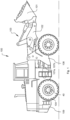
- Fig. 1 is an illustration of a working machine 100 in the form of a wheel loader.
- the wheel loader 100 is an example of a working machine in which a powertrain according to embodiments of the invention can be applied.
- the wheel loader 100 has a bucket 101 which is arranged on a load arm 102 for lifting and lowering the bucket 101.
- the wheel loader 100 comprises a hydraulic system 103 for lifting, lowering and tilting the bucket 101.
- the hydraulic system 103 is further configured for steering of the working machine 100 by means of two hydraulic cylinders 107a, 107b arranged on opposite sides of the wheel loader for turning the wheel loader by means of relative movement of a front body part 108 and a rear body part 109.
- the working machine is frame-steered by means of the steering cylinders 107a, 107b.
- the wheel loader is driven by an electric powertrain (not shown in fig. 1 ), configured for propulsion of the wheel loader 100 via drive wheels 104 mounted on a propulsion axle 40, as well as for driving at least one hydraulic machine of the hydraulic system 103 via a power take-off (not shown in fig. 1 ).
- the hydraulic machine(s) may preferably be at least one machine configured to function as a hydraulic pump as well as a hydraulic motor with a reversed flow of hydraulic fluid.
- Such a hydraulic machine with said both functions can be used as a pump for providing the hydraulic system with hydraulic fluid, for example to lift and tilt the bucket 101, and as a hydraulic motor for recuperation of energy, for example during a lowering operation of the load arm 102.
- the wheel loader 100 further comprises an energy storage system (not shown) for providing electric energy to the electric powertrain.
- Components of an electric powertrain 200 according to a first embodiment, which may be used in the wheel loader 100, are schematically illustrated in fig. 2 .
- the illustrated powertrain 200 comprises a first electric machine 20, which is drivingly connectable to at least one propulsion axle (not shown in fig. 2 ), for example the propulsion axle 40 and drive wheels 104 as shown in fig. 1 , for propulsion of the working machine 100 via a transmission assembly 1.
- the first electric machine 20 is dimensioned and configured for propulsion of the working machine 100 in a forward as well as a rearward direction.
- the powertrain 200 further comprises a second electric machine 30, which is drivingly connected to a power take-off 50 and may for instance be used for driving the hydraulic machine of the hydraulic system 103.
- the second electric machine may in this case be dimensioned and configured for powering the hydraulic machine for lifting, lowering and tilting the bucket 101 and for frame steering of the wheel loader.
- a first input shaft 2 of the transmission assembly 1 is drivingly connected to the first electric machine 20.
- a first output shaft 4 of the transmission assembly 1 is drivingly connected to the propulsion axle 40 and the drive wheels 104 (not shown in fig. 2 ), and is further selectively drivingly connectable to the first input shaft 2 via a set of selectively engageable gears 6, so that torque may be transferred from the first electric machine 20 to the propulsion axle via the first input shaft 2, the set of selectively engageable gears 6, and the first output shaft 4.
- the first input shaft 2 is independently drivingly connectable to the first output shaft 4 via the set of selectively engageable gears 6, such that the first electric machine 20 may be used for propulsion by itself, independently of the second electric machine 30.
- a second input shaft 3 of the transmission assembly 1 is drivingly connected to the second electric machine 30.
- a second output shaft 5 for power take-off from the working machine 100 is drivingly connected to the hydraulic pump and to the second input shaft 3, so that torque is transferred from the second electric machine 30 to the hydraulic pump via the second input shaft 3 and the second output shaft 5.
- the second input shaft 3 is furthermore drivingly connectable to the first output shaft 4, so that torque generated by the second electric machine 30 may be transferred to the propulsion axle.
- the set of selectively engageable gears 6 illustrated in fig. 2 comprises two selectable gear ratios for transfer of torque.
- a desired gear ratio is selected by engaging one of a set of first clutches 8a, 8b, wherein each one of the first clutches 8a, 8b is configured for selectively engaging one gear of the set of selectively engageable gears.
- the first clutches 8a, 8b are herein in the form of a first friction clutch 8a and a second friction clutch 8b.
- first friction clutch 8a Upon engagement of the first friction clutch 8a, torque is transferable from the first input shaft 2 to the first output shaft 4 via a first input gear wheel 6a connected for common rotation with the first input shaft 2, a first intermediate gear wheel 6b connected for common rotation with an intermediate shaft 10, a second intermediate gear wheel 6c connected for common rotation with the intermediate shaft 10 by means of the first friction clutch 8a, and a first output gear wheel 6d connected for common rotation with the first output shaft 4.
- Corresponding gear wheels, such as the first input gear wheel 6a and the first intermediate gear wheel 6b, are in meshing engagement. This gear ratio is suitable for driving at relatively low speeds.
- a second clutch 9 in the form of a dog clutch is further provided for selectively drivingly connecting the second input shaft 3 to the first output shaft 4.
- a third input gear wheel 11 is connected for common rotation with the second input shaft 3. Torque is thereby transferable via the third input gear wheel 11, the second input gear wheel 6e, the second intermediate gear wheel 6c, and the first output gear wheel 6d.
- a single gear ratio is provided for selective torque transfer between the second electric machine 30 and the first output shaft 4.
- the second input shaft 3 is independently selectively drivingly connectable to the first output shaft 4, i.e. it may be connected without simultaneous connection of the first input shaft 2.
- both friction clutches 8a, 8b may be disengaged while torque is transferred from the second electric machine 30 to the first output shaft 4. While shifting gears for torque transfer between the first electric machine 20 and the first output shaft 4, torque may therefore be transferred continuously without disruption between the second electric machine 30 and the first output shaft 4.
- the second input shaft 3 is herein drivingly connectable to the first output shaft 4 by means of meshing engagement between on one hand the third input gear wheel 11, selectively connectable to the second input shaft 3 by means of the second clutch 9, and on the other hand the second input gear wheel 6e, selectively connectable to the first input shaft 2 by means of the second friction clutch 8b, wherein the second input gear wheel 6e is in turn in meshing engagement with the second intermediate gear wheel 6c, meshing with the first output gear wheel 6d.
- the second electric machine 30 is drivingly connected to the second output shaft 5 via a fourth input gear wheel 12a, connected for common rotation with the second input shaft 3, and a second output gear wheel 12b, connected for common rotation with the second output shaft 5.
- a fourth input gear wheel 12a connected for common rotation with the second input shaft 3
- a second output gear wheel 12b connected for common rotation with the second output shaft 5.
- the transmission assembly 1 is contained within a schematically illustrated transmission housing 13. Bearings marked by crosses are provided between the transmission housing 13 and the input and output shafts 2, 3, 4, 5, as well as the intermediate shaft 10.
- An electric powertrain 200 according to a second embodiment is shown in fig. 3 .
- the second embodiment does not fall within the scope of the claimed invention.
- the individual components of the second embodiment and the configuration of the set of selectively engageable gears 6 are similar to the first embodiment, and will therefore not be described in detail.
- the powertrain 200 according to the second embodiment differs from the powertrain according to the first embodiment in that the third input gear wheel 11, which is selectively connectable to the second input shaft 3 by means of the second clutch 9, is in meshing engagement with the first input gear wheel 6a. In this way, torque generated by the second electric machine 30 may only be transferred to the first output shaft 4 via the set of selectively engageable gears 6.
- the different gear ratios provided within the same transmission assembly 1 are used for transferring torque generated by both electric machines 20, 30 to the first output shaft 4 for propulsion of the working machine 100.
- the second input shaft 3 is at all times drivingly connected to the second output shaft 5 via the fourth input gear wheel 12a, and the second output gear wheel 12b, regardless of whether the second clutch 9 is engaged or not.
- the second input shaft 3 is in this embodiment only drivingly connectable to the first output shaft 4 when also the first input shaft 2 is drivingly connected first output shaft 4, since both input shafts 2, 3 use the set of selectively engageable gears 6 for connection.
- the first input shaft 2 is however independently drivingly connectable to the first output shaft 4 upon disengagement of the second clutch 9.
- torque from the first electric machine 20 may also be transferred to the second output shaft 5 upon engagement of the second clutch 9, in this case via the first input shaft 2, the first input gear wheel 6a, the third input gear wheel 11, the second input shaft 3, the fourth input gear wheel 12a, and the second output gear wheel 12b. If at the same time the first clutches 8a, 8b are disengaged, no torque is transferred to the first output shaft 4 for propulsion of the working machine. Instead, torque from both the electric machines 20, 30 is transferred to the second output shaft 5.
- An electric powertrain 200 according to a third embodiment is shown in fig. 4 , in line with the claimed invention.
- the individual components of the third embodiment which are similar to the first embodiment will not be described in detail.
- the powertrain 200 according to the third embodiment differs from the powertrain according to the first embodiment in that the set of selectively engageable gears 6 of the transmission assembly 1 comprises three selectable gear ratios.
- Three first clutches 8a, 8b, 8c comprising a first friction clutch 8a for engaging a low speed gear, a second friction clutch 8b for engaging a medium speed gear, and a third friction clutch 8c for engaging a high speed gear are provided for this purpose.
- a reduction gear 7 is provided for reducing a rotational speed and increasing the torque transferred from the first electric machine 20 at all three gears.
- An exemplary torque path T1 for transfer of torque at the medium speed gear is illustrated by a dashed line, wherein torque generated by the first electric machine 20 is transferred to the first output shaft 4 via the reduction gear 7 and further via the second friction clutch 8b.
- the second clutch 9 is provided such that torque generated by the second electric machine 30 is selectively transferable to the first output shaft 4 at a single gear ratio upon engagement of the second clutch 9, bypassing the set of selectively engageable gears 6.
- An electric powertrain 200 according to a fourth embodiment is shown in fig. 5 .
- the powertrain 200 of this embodiment is similar to the powertrain of the third embodiment, but with the second clutch 9 arranged such that it selectively connects the second input shaft 3 to the first output shaft 4 via the reduction gear 7 and the set of selectively engageable gears 6, similarly to the second embodiment shown in fig. 3 .
- An exemplary torque path T2 for transfer of torque at the low speed gear is illustrated by a dashed line, wherein torque generated by the second electric machine 30 is transferred to the first output shaft 4 via the engaged second clutch 9 (shown in a disengaged position in fig. 5 ), the reduction gear 7 and further via the first friction clutch 8a.
- the second input shaft 3 is at all times drivingly connected to the second output shaft 5. If the first electric machine 20 is also generating torque, torque is simultaneously transferred from the first electric machine 20 via the low speed gear.
- the electric machines 20, 30 may in all embodiments be electric machines of the same type or of different types.
- the electric machines may be configured to be drivable in both directions.
- the electric machines 20, 30 may be of a type that can regenerate energy and thereby be used for regenerative braking.
- At least one of the machines may e.g. be a direct current (DC) motor, such as a brushless DC motors. It is also possible that at least one of the machines may be an alternating current (AC) motor.
- DC direct current
- AC alternating current
- universal motors, or induction motors, or other types of electric motors may be used, alone or in combination with the above mentioned types of motors.
Landscapes
- Engineering & Computer Science (AREA)
- Mechanical Engineering (AREA)
- Chemical & Material Sciences (AREA)
- Combustion & Propulsion (AREA)
- Transportation (AREA)
- General Engineering & Computer Science (AREA)
- Mining & Mineral Resources (AREA)
- Civil Engineering (AREA)
- Structural Engineering (AREA)
- Structure Of Transmissions (AREA)
Claims (9)
- Elektrischer Antriebsstrang (200) für eine Arbeitsmaschine (100), der Antriebsstrang umfassend:- eine erste elektrische Maschine (20),- eine zweite elektrische Maschine (30),- mindestens eine Vortriebsachse (40) für einen Vortrieb der Arbeitsmaschine (100),- eine Getriebeanordnung (1), umfassend:o eine erste Eingangswelle (2), die mit der ersten elektrischen Maschine (20) triebmäßig verbunden ist,o eine zweite Eingangswelle (3), die mit der zweiten elektrischen Maschine (30) triebmäßig verbunden ist,o eine erste Ausgangswelle (4), die mit der mindestens einen Vortriebsachse (40) triebmäßig verbunden ist, wobei die erste Eingangswelle (2) und die zweite Eingangswelle (3) mit der ersten Ausgangswelle (4) wahlweise triebmäßig verbindbar sind,o mindestens eine zweite Ausgangswelle (5) für einen Abtrieb von dem elektrischen Antriebsstrang (200), wobei die zweite Eingangswelle (3) mit der mindestens einen zweiten Ausgangswelle (5) triebmäßig verbunden ist,o einen Satz wahlweise einlegbarer Gänge (6), umfassend mindestens zwei wählbare Übersetzungsverhältnisse für eine Drehmomentübertragung,o einen Satz erster Kupplungen (8a, 8b, 8c), wobei jede der ersten Kupplungen (8a, 8b, 8c) zum wahlweisen Einlegen eines Gangs des Satzes wahlweise einlegbarer Gänge (6) konfiguriert ist,o eine zweite Kupplung (9) zum wahlweisen triebmäßig Verbinden der zweiten Eingangswelle (3) mit der ersten Ausgangswelle (4),wobei mindestens die erste Eingangswelle (2) über den Satz wahlweise einlegbarer Gänge (6) mit der ersten Ausgangswelle (4) triebmäßig verbunden ist,dadurch gekennzeichnet, dassdie zweite Eingangswelle (3) mit der ersten Ausgangswelle (4) unabhängig wahlweise triebmäßig verbindbar ist, die ersten Kupplungen (8a, 8b, 8c) Reibungskupplungen sind und die zweite Kupplung (9) eine Klauenkupplung ist.
- Antriebsstrang nach Anspruch 1, wobei mindestens die erste Eingangswelle (2) mit der ersten Ausgangswelle (4) unabhängig wahlweise triebmäßig verbindbar ist.
- Antriebsstrang nach Anspruch 1 oder 2, wobei der Satz wahlweise einlegbarer Gänge mindestens drei wählbare Übersetzungsverhältnisse umfasst.
- Antriebsstrang nach einem der vorstehenden Ansprüche, wobei zum triebmäßig Verbinden der zweiten Eingangswelle (3) mit der ersten Ausgangswelle (4) ein einziges Übersetzungsverhältnis bereitgestellt ist.
- Antriebsstrang nach einem der vorstehenden Ansprüche, ferner umfassend ein Reduktionsgetriebe (7), das für die Drehmomentübertragung zwischen mindestens der ersten Eingangswelle (2) und dem Satz wahlweise einlegbarer Gänge (6) arrangiert ist.
- Arbeitsmaschine (100), umfassend einen Antriebsstrang (200) nach einem der vorstehenden Ansprüche.
- Arbeitsmaschine nach Anspruch 6, ferner umfassend mindestens ein Ausrüstungsteil, das konfiguriert ist, um durch die mindestens eine zweite Ausgangswelle (5) für den Abtrieb getrieben zu werden.
- Arbeitsmaschine nach Anspruch 7, wobei das mindestens eine Ausrüstungsteil mindestens eine Hydraulikpumpe umfasst.
- Arbeitsmaschine nach einem der Ansprüche 6 bis 8, wobei die Arbeitsmaschine (100) ein Radlader oder ein Radbagger ist.
Applications Claiming Priority (1)
| Application Number | Priority Date | Filing Date | Title |
|---|---|---|---|
| PCT/EP2019/086228 WO2021121594A1 (en) | 2019-12-19 | 2019-12-19 | An electric powertrain and a working machine |
Publications (3)
| Publication Number | Publication Date |
|---|---|
| EP4077008A1 EP4077008A1 (de) | 2022-10-26 |
| EP4077008B1 true EP4077008B1 (de) | 2024-08-28 |
| EP4077008C0 EP4077008C0 (de) | 2024-08-28 |
Family
ID=69156382
Family Applications (1)
| Application Number | Title | Priority Date | Filing Date |
|---|---|---|---|
| EP19835282.5A Active EP4077008B1 (de) | 2019-12-19 | 2019-12-19 | Elektrischer antriebsstrang und arbeitsmaschine |
Country Status (4)
| Country | Link |
|---|---|
| US (1) | US11859368B2 (de) |
| EP (1) | EP4077008B1 (de) |
| CN (1) | CN114829179A (de) |
| WO (1) | WO2021121594A1 (de) |
Families Citing this family (6)
| Publication number | Priority date | Publication date | Assignee | Title |
|---|---|---|---|---|
| SE2050926A1 (en) * | 2020-07-29 | 2021-11-16 | Man Truck & Bus Ag | Transmission unit, transmission arrangement and vehicle powertrain |
| US11655863B1 (en) | 2021-11-17 | 2023-05-23 | Dana Belgium N.V. | Electric driveline system with power take-off and electric driveline system operating method |
| FR3131711A1 (fr) * | 2022-01-08 | 2023-07-14 | Valeo Embrayages | Systeme de propulsion pour vehicule electrique |
| US12007004B2 (en) * | 2022-05-02 | 2024-06-11 | Dana Belgium N.V. | Electric drive unit with a multi-speed transmission and method for transmission operation |
| EP4282684A1 (de) | 2022-05-24 | 2023-11-29 | Volvo Construction Equipment AB | Kraftübertragungsanordnung |
| KR20250130948A (ko) * | 2024-02-26 | 2025-09-02 | 한국생산기술연구원 | 전동 모빌리티의 구동 시스템 및 이를 포함하는 전동 트랙터 |
Citations (3)
| Publication number | Priority date | Publication date | Assignee | Title |
|---|---|---|---|---|
| DE102019203724A1 (de) * | 2019-03-19 | 2020-09-24 | Zf Friedrichshafen Ag | Verfahren zum Betreiben eines Antriebsstrangs für eine Arbeitsmaschine, Antriebsstrang für eine Arbeitsmaschine und Arbeitsmaschine |
| DE102019203730A1 (de) * | 2019-03-19 | 2020-09-24 | Zf Friedrichshafen Ag | Verfahren zum Betreiben eines Antriebsstrangs für eine Arbeitsmaschine, Antriebsstrang für eine Arbeitsmaschine und Arbeitsmaschine |
| WO2021058429A1 (de) * | 2019-09-23 | 2021-04-01 | Zf Friedrichshafen Ag | Verfahren zum betreiben eines antriebsstrangs für eine arbeitsmaschine, antriebsstrang für eine arbeitsmaschine und arbeitsmaschine |
Family Cites Families (8)
| Publication number | Priority date | Publication date | Assignee | Title |
|---|---|---|---|---|
| JP2002356116A (ja) * | 2001-05-30 | 2002-12-10 | Iseki & Co Ltd | 電動式動力車両 |
| JP5826037B2 (ja) | 2012-01-10 | 2015-12-02 | 株式会社クボタ | 電動トラクタ |
| US9568080B2 (en) * | 2014-01-30 | 2017-02-14 | Byd Company Limited | Power transmission system for vehicle and vehicle comprising the same |
| DE102018222251A1 (de) | 2018-12-19 | 2020-06-25 | Zf Friedrichshafen Ag | Antriebsvorrichtung zum Antrieb einer Fahrzeugachse und Verfahren zum Betreiben der Antriebsvorrichtung |
| CN110203069A (zh) * | 2019-06-10 | 2019-09-06 | 芜湖安佳捷汽车科技有限公司 | 一种新型4x4纯电动双头驾驶传动及取力系统 |
| DE102020005394A1 (de) * | 2020-09-03 | 2022-03-03 | Daimler Ag | Elektrisches Antriebssystem |
| US11982348B2 (en) * | 2021-10-01 | 2024-05-14 | Dana Belgium N.V. | Dual double synchronizer e-transmission for reducing torque interruption during gear shifts |
| US11655863B1 (en) * | 2021-11-17 | 2023-05-23 | Dana Belgium N.V. | Electric driveline system with power take-off and electric driveline system operating method |
-
2019
- 2019-12-19 CN CN201980102969.0A patent/CN114829179A/zh active Pending
- 2019-12-19 WO PCT/EP2019/086228 patent/WO2021121594A1/en not_active Ceased
- 2019-12-19 US US17/785,305 patent/US11859368B2/en active Active
- 2019-12-19 EP EP19835282.5A patent/EP4077008B1/de active Active
Patent Citations (3)
| Publication number | Priority date | Publication date | Assignee | Title |
|---|---|---|---|---|
| DE102019203724A1 (de) * | 2019-03-19 | 2020-09-24 | Zf Friedrichshafen Ag | Verfahren zum Betreiben eines Antriebsstrangs für eine Arbeitsmaschine, Antriebsstrang für eine Arbeitsmaschine und Arbeitsmaschine |
| DE102019203730A1 (de) * | 2019-03-19 | 2020-09-24 | Zf Friedrichshafen Ag | Verfahren zum Betreiben eines Antriebsstrangs für eine Arbeitsmaschine, Antriebsstrang für eine Arbeitsmaschine und Arbeitsmaschine |
| WO2021058429A1 (de) * | 2019-09-23 | 2021-04-01 | Zf Friedrichshafen Ag | Verfahren zum betreiben eines antriebsstrangs für eine arbeitsmaschine, antriebsstrang für eine arbeitsmaschine und arbeitsmaschine |
Also Published As
| Publication number | Publication date |
|---|---|
| EP4077008A1 (de) | 2022-10-26 |
| US20230029811A1 (en) | 2023-02-02 |
| EP4077008C0 (de) | 2024-08-28 |
| WO2021121594A1 (en) | 2021-06-24 |
| US11859368B2 (en) | 2024-01-02 |
| CN114829179A (zh) | 2022-07-29 |
Similar Documents
| Publication | Publication Date | Title |
|---|---|---|
| EP4077008B1 (de) | Elektrischer antriebsstrang und arbeitsmaschine | |
| EP2427357B1 (de) | Arbeitsmaschine und verfahren zum betrieb einer arbeitsmaschine | |
| US8747269B2 (en) | Continuously variable transmission and a working machine including a continuously variable transmission | |
| US8347998B2 (en) | Working machine with one or more electric machines for driving, braking, and/or generating power and a method for operating such a working machine | |
| EP2487299A1 (de) | Baumaschinen | |
| US9598835B2 (en) | Continuously variable transmission and a working machine including a continuously variable transmission | |
| EP2567123B1 (de) | Stufenlos verstellbares getriebe und arbeitsmaschine | |
| US9285015B2 (en) | Continuously variable transmission and a working machine including a continuously variable transmission | |
| EP1937904B1 (de) | Arbeitsmaschine | |
| WO2011081593A1 (en) | Electric hybrid system | |
| WO2016159846A1 (en) | A transmission arrangement for a vehicle | |
| EP4282684A1 (de) | Kraftübertragungsanordnung |
Legal Events
| Date | Code | Title | Description |
|---|---|---|---|
| STAA | Information on the status of an ep patent application or granted ep patent |
Free format text: STATUS: UNKNOWN |
|
| STAA | Information on the status of an ep patent application or granted ep patent |
Free format text: STATUS: THE INTERNATIONAL PUBLICATION HAS BEEN MADE |
|
| PUAI | Public reference made under article 153(3) epc to a published international application that has entered the european phase |
Free format text: ORIGINAL CODE: 0009012 |
|
| STAA | Information on the status of an ep patent application or granted ep patent |
Free format text: STATUS: REQUEST FOR EXAMINATION WAS MADE |
|
| 17P | Request for examination filed |
Effective date: 20220705 |
|
| AK | Designated contracting states |
Kind code of ref document: A1 Designated state(s): AL AT BE BG CH CY CZ DE DK EE ES FI FR GB GR HR HU IE IS IT LI LT LU LV MC MK MT NL NO PL PT RO RS SE SI SK SM TR |
|
| DAV | Request for validation of the european patent (deleted) | ||
| DAX | Request for extension of the european patent (deleted) | ||
| STAA | Information on the status of an ep patent application or granted ep patent |
Free format text: STATUS: EXAMINATION IS IN PROGRESS |
|
| 17Q | First examination report despatched |
Effective date: 20230921 |
|
| GRAP | Despatch of communication of intention to grant a patent |
Free format text: ORIGINAL CODE: EPIDOSNIGR1 |
|
| STAA | Information on the status of an ep patent application or granted ep patent |
Free format text: STATUS: GRANT OF PATENT IS INTENDED |
|
| INTG | Intention to grant announced |
Effective date: 20240416 |
|
| GRAS | Grant fee paid |
Free format text: ORIGINAL CODE: EPIDOSNIGR3 |
|
| GRAA | (expected) grant |
Free format text: ORIGINAL CODE: 0009210 |
|
| STAA | Information on the status of an ep patent application or granted ep patent |
Free format text: STATUS: THE PATENT HAS BEEN GRANTED |
|
| AK | Designated contracting states |
Kind code of ref document: B1 Designated state(s): AL AT BE BG CH CY CZ DE DK EE ES FI FR GB GR HR HU IE IS IT LI LT LU LV MC MK MT NL NO PL PT RO RS SE SI SK SM TR |
|
| REG | Reference to a national code |
Ref country code: CH Ref legal event code: EP |
|
| REG | Reference to a national code |
Ref country code: DE Ref legal event code: R096 Ref document number: 602019058012 Country of ref document: DE |
|
| REG | Reference to a national code |
Ref country code: IE Ref legal event code: FG4D |
|
| U01 | Request for unitary effect filed |
Effective date: 20240926 |
|
| U07 | Unitary effect registered |
Designated state(s): AT BE BG DE DK EE FI FR IT LT LU LV MT NL PT RO SE SI Effective date: 20241024 |
|
| PG25 | Lapsed in a contracting state [announced via postgrant information from national office to epo] |
Ref country code: NO Free format text: LAPSE BECAUSE OF FAILURE TO SUBMIT A TRANSLATION OF THE DESCRIPTION OR TO PAY THE FEE WITHIN THE PRESCRIBED TIME-LIMIT Effective date: 20241128 |
|
| PG25 | Lapsed in a contracting state [announced via postgrant information from national office to epo] |
Ref country code: PL Free format text: LAPSE BECAUSE OF FAILURE TO SUBMIT A TRANSLATION OF THE DESCRIPTION OR TO PAY THE FEE WITHIN THE PRESCRIBED TIME-LIMIT Effective date: 20240828 Ref country code: GR Free format text: LAPSE BECAUSE OF FAILURE TO SUBMIT A TRANSLATION OF THE DESCRIPTION OR TO PAY THE FEE WITHIN THE PRESCRIBED TIME-LIMIT Effective date: 20241129 |
|
| PG25 | Lapsed in a contracting state [announced via postgrant information from national office to epo] |
Ref country code: IS Free format text: LAPSE BECAUSE OF FAILURE TO SUBMIT A TRANSLATION OF THE DESCRIPTION OR TO PAY THE FEE WITHIN THE PRESCRIBED TIME-LIMIT Effective date: 20241228 |
|
| PG25 | Lapsed in a contracting state [announced via postgrant information from national office to epo] |
Ref country code: HR Free format text: LAPSE BECAUSE OF FAILURE TO SUBMIT A TRANSLATION OF THE DESCRIPTION OR TO PAY THE FEE WITHIN THE PRESCRIBED TIME-LIMIT Effective date: 20240828 |
|
| PG25 | Lapsed in a contracting state [announced via postgrant information from national office to epo] |
Ref country code: RS Free format text: LAPSE BECAUSE OF FAILURE TO SUBMIT A TRANSLATION OF THE DESCRIPTION OR TO PAY THE FEE WITHIN THE PRESCRIBED TIME-LIMIT Effective date: 20241128 Ref country code: ES Free format text: LAPSE BECAUSE OF FAILURE TO SUBMIT A TRANSLATION OF THE DESCRIPTION OR TO PAY THE FEE WITHIN THE PRESCRIBED TIME-LIMIT Effective date: 20240828 |
|
| U20 | Renewal fee for the european patent with unitary effect paid |
Year of fee payment: 6 Effective date: 20241225 |
|
| PG25 | Lapsed in a contracting state [announced via postgrant information from national office to epo] |
Ref country code: RS Free format text: LAPSE BECAUSE OF FAILURE TO SUBMIT A TRANSLATION OF THE DESCRIPTION OR TO PAY THE FEE WITHIN THE PRESCRIBED TIME-LIMIT Effective date: 20241128 Ref country code: PL Free format text: LAPSE BECAUSE OF FAILURE TO SUBMIT A TRANSLATION OF THE DESCRIPTION OR TO PAY THE FEE WITHIN THE PRESCRIBED TIME-LIMIT Effective date: 20240828 Ref country code: NO Free format text: LAPSE BECAUSE OF FAILURE TO SUBMIT A TRANSLATION OF THE DESCRIPTION OR TO PAY THE FEE WITHIN THE PRESCRIBED TIME-LIMIT Effective date: 20241128 Ref country code: IS Free format text: LAPSE BECAUSE OF FAILURE TO SUBMIT A TRANSLATION OF THE DESCRIPTION OR TO PAY THE FEE WITHIN THE PRESCRIBED TIME-LIMIT Effective date: 20241228 Ref country code: HR Free format text: LAPSE BECAUSE OF FAILURE TO SUBMIT A TRANSLATION OF THE DESCRIPTION OR TO PAY THE FEE WITHIN THE PRESCRIBED TIME-LIMIT Effective date: 20240828 Ref country code: GR Free format text: LAPSE BECAUSE OF FAILURE TO SUBMIT A TRANSLATION OF THE DESCRIPTION OR TO PAY THE FEE WITHIN THE PRESCRIBED TIME-LIMIT Effective date: 20241129 Ref country code: ES Free format text: LAPSE BECAUSE OF FAILURE TO SUBMIT A TRANSLATION OF THE DESCRIPTION OR TO PAY THE FEE WITHIN THE PRESCRIBED TIME-LIMIT Effective date: 20240828 |
|
| PG25 | Lapsed in a contracting state [announced via postgrant information from national office to epo] |
Ref country code: SM Free format text: LAPSE BECAUSE OF FAILURE TO SUBMIT A TRANSLATION OF THE DESCRIPTION OR TO PAY THE FEE WITHIN THE PRESCRIBED TIME-LIMIT Effective date: 20240828 |
|
| PG25 | Lapsed in a contracting state [announced via postgrant information from national office to epo] |
Ref country code: CZ Free format text: LAPSE BECAUSE OF FAILURE TO SUBMIT A TRANSLATION OF THE DESCRIPTION OR TO PAY THE FEE WITHIN THE PRESCRIBED TIME-LIMIT Effective date: 20240828 |
|
| PG25 | Lapsed in a contracting state [announced via postgrant information from national office to epo] |
Ref country code: SK Free format text: LAPSE BECAUSE OF FAILURE TO SUBMIT A TRANSLATION OF THE DESCRIPTION OR TO PAY THE FEE WITHIN THE PRESCRIBED TIME-LIMIT Effective date: 20240828 |
|
| PLBE | No opposition filed within time limit |
Free format text: ORIGINAL CODE: 0009261 |
|
| STAA | Information on the status of an ep patent application or granted ep patent |
Free format text: STATUS: NO OPPOSITION FILED WITHIN TIME LIMIT |
|
| PG25 | Lapsed in a contracting state [announced via postgrant information from national office to epo] |
Ref country code: MC Free format text: LAPSE BECAUSE OF FAILURE TO SUBMIT A TRANSLATION OF THE DESCRIPTION OR TO PAY THE FEE WITHIN THE PRESCRIBED TIME-LIMIT Effective date: 20240828 |
|
| REG | Reference to a national code |
Ref country code: CH Ref legal event code: PL |
|
| 26N | No opposition filed |
Effective date: 20250530 |
|
| GBPC | Gb: european patent ceased through non-payment of renewal fee |
Effective date: 20241219 |
|
| PG25 | Lapsed in a contracting state [announced via postgrant information from national office to epo] |
Ref country code: GB Free format text: LAPSE BECAUSE OF NON-PAYMENT OF DUE FEES Effective date: 20241219 |
|
| PG25 | Lapsed in a contracting state [announced via postgrant information from national office to epo] |
Ref country code: CH Free format text: LAPSE BECAUSE OF NON-PAYMENT OF DUE FEES Effective date: 20241231 |
|
| PG25 | Lapsed in a contracting state [announced via postgrant information from national office to epo] |
Ref country code: IE Free format text: LAPSE BECAUSE OF NON-PAYMENT OF DUE FEES Effective date: 20241219 |
|
| U20 | Renewal fee for the european patent with unitary effect paid |
Year of fee payment: 7 Effective date: 20251223 |