EP4075911B1 - Network allocation vector management - Google Patents
Network allocation vector management Download PDFInfo
- Publication number
- EP4075911B1 EP4075911B1 EP22177328.6A EP22177328A EP4075911B1 EP 4075911 B1 EP4075911 B1 EP 4075911B1 EP 22177328 A EP22177328 A EP 22177328A EP 4075911 B1 EP4075911 B1 EP 4075911B1
- Authority
- EP
- European Patent Office
- Prior art keywords
- duration
- field
- txop
- sta
- value
- Prior art date
- Legal status (The legal status is an assumption and is not a legal conclusion. Google has not performed a legal analysis and makes no representation as to the accuracy of the status listed.)
- Active
Links
Images











Classifications
-
- H—ELECTRICITY
- H04—ELECTRIC COMMUNICATION TECHNIQUE
- H04W—WIRELESS COMMUNICATION NETWORKS
- H04W72/00—Local resource management
- H04W72/04—Wireless resource allocation
- H04W72/044—Wireless resource allocation based on the type of the allocated resource
-
- H—ELECTRICITY
- H04—ELECTRIC COMMUNICATION TECHNIQUE
- H04W—WIRELESS COMMUNICATION NETWORKS
- H04W84/00—Network topologies
- H04W84/02—Hierarchically pre-organised networks, e.g. paging networks, cellular networks, WLAN [Wireless Local Area Network] or WLL [Wireless Local Loop]
- H04W84/10—Small scale networks; Flat hierarchical networks
- H04W84/12—WLAN [Wireless Local Area Networks]
-
- H—ELECTRICITY
- H04—ELECTRIC COMMUNICATION TECHNIQUE
- H04L—TRANSMISSION OF DIGITAL INFORMATION, e.g. TELEGRAPHIC COMMUNICATION
- H04L1/00—Arrangements for detecting or preventing errors in the information received
-
- H—ELECTRICITY
- H04—ELECTRIC COMMUNICATION TECHNIQUE
- H04W—WIRELESS COMMUNICATION NETWORKS
- H04W28/00—Network traffic management; Network resource management
- H04W28/02—Traffic management, e.g. flow control or congestion control
- H04W28/06—Optimizing the usage of the radio link, e.g. header compression, information sizing, discarding information
- H04W28/065—Optimizing the usage of the radio link, e.g. header compression, information sizing, discarding information using assembly or disassembly of packets
-
- H—ELECTRICITY
- H04—ELECTRIC COMMUNICATION TECHNIQUE
- H04W—WIRELESS COMMUNICATION NETWORKS
- H04W72/00—Local resource management
- H04W72/04—Wireless resource allocation
-
- H—ELECTRICITY
- H04—ELECTRIC COMMUNICATION TECHNIQUE
- H04W—WIRELESS COMMUNICATION NETWORKS
- H04W74/00—Wireless channel access
- H04W74/002—Transmission of channel access control information
- H04W74/006—Transmission of channel access control information in the downlink, i.e. towards the terminal
-
- H—ELECTRICITY
- H04—ELECTRIC COMMUNICATION TECHNIQUE
- H04L—TRANSMISSION OF DIGITAL INFORMATION, e.g. TELEGRAPHIC COMMUNICATION
- H04L1/00—Arrangements for detecting or preventing errors in the information received
- H04L1/004—Arrangements for detecting or preventing errors in the information received by using forward error control
- H04L1/0075—Transmission of coding parameters to receiver
-
- H—ELECTRICITY
- H04—ELECTRIC COMMUNICATION TECHNIQUE
- H04W—WIRELESS COMMUNICATION NETWORKS
- H04W88/00—Devices specially adapted for wireless communication networks, e.g. terminals, base stations or access point devices
- H04W88/08—Access point devices
Definitions
- FIG. 1 is a diagram illustrating an exemplary configuration of a WLAN system.
- the BSS illustrated in FIG. 1 is the IBSS.
- the IBSS refers to a BSS that does not include an AP. Since the IBSS does not include the AP, the IBSS is not allowed to access to the DS and thus forms a self-contained network.
- a Station Management Entity resides in each STA.
- the SME is a layer independent entity which may be perceived as being present in a separate management plane or as being off to the side. While specific functions of the SME are not described in detail herein, the SME may be responsible for collecting layer-dependent states from various Layer Management Entities (LMEs) and setting layer-specific parameters to similar values. The SME may execute these functions and implement a standard management protocol on behalf of general system management entities.
- LMEs Layer Management Entities
- STA may perform the network discovery action.
- the network discovery action may include the STA scanning action. That is, STA must search for an available network so as to access the network.
- the STA must identify a compatible network before participating in a wireless network.
- the process for identifying the network contained in a specific region is referred to as a scanning process.
- the authentication frame may include an authentication algorithm number, an authentication transaction sequence number, a state code, a challenge text, a Robust Security Network (RSN), a Finite Cyclic Group (FCG), etc.
- the above-mentioned information contained in the authentication frame may correspond to some parts of information capable of being contained in the authentication request/response frame, may be replaced with other information, or may include additional information.
- the STA may transmit the authentication request frame to the AP.
- the AP may decide whether to authenticate the corresponding STA on the basis of information contained in the received authentication request frame.
- the AP may provide the authentication result to the STA through the authentication response frame.
- the association response frame may include information associated with various capabilities, a state code, an Association ID (AID), supported rates, an Enhanced Distributed Channel Access (EDCA) parameter set, a Received Channel Power Indicator (RCPI), a Received Signal to Noise Indicator (RSNI), mobility domain, a timeout interval (association comeback time), an overlapping BSS scan parameter, a TIM broadcast response, a Quality of Service (QoS) map, etc.
- AID Association ID
- EDCA Enhanced Distributed Channel Access
- RCPI Received Channel Power Indicator
- RSNI Received Signal to Noise Indicator
- mobility domain a timeout interval (association comeback time)
- association comeback time an overlapping BSS scan parameter
- a TIM broadcast response a Quality of Service (QoS) map, etc.
- QoS Quality of Service
- a security setup process may be carried out in step S540.
- the security setup process of Step S540 may be referred to as an authentication process based on Robust Security Network Association (RSNA) request/response.
- the authentication process of step S520 may be referred to as a first authentication process, and the security setup process of Step S540 may also be simply referred to as an authentication process.
- RSNA Robust Security Network Association
- a basic access mechanism of Medium Access Control is a Carrier Sense Multiple Access with Collision Avoidance (CSMA/CA) mechanism.
- the CSMA/CA mechanism is referred to as a Distributed Coordination Function (DCF) of IEEE 802.11 MAC, and basically includes a "Listen Before Talk" access mechanism.
- DCF Distributed Coordination Function
- the AP and/or STA may perform Clear Channel Assessment (CCA) for sensing an RF channel or medium during a predetermined time interval [for example, DCF Inter-Frame Space (DIFS)], prior to data transmission. If it is determined that the medium is in the idle state, frame transmission through the corresponding medium begins.
- CCA Clear Channel Assessment
- HCF Hybrid Coordination Function
- PCF Point Coordination Function
- EDCA Enhanced Distributed Channel Access
- HCCA HCF Controlled Channel Access
- EDCA is achieved when the access scheme provided from a provider to a plurality of users is contention-based.
- HCCA is achieved by the contention-free-based channel access scheme based on the polling mechanism.
- HCF includes a medium access mechanism for improving Quality of Service (QoS) of WLAN, and may transmit QoS data in both a Contention Period (CP) and a Contention Free Period (CFP).
- QoS Quality of Service
- each STA selects a random backoff count, waits for a slot time corresponding to the selected backoff count, and then attempts to start data transmission.
- the random backoff count has a value of a Packet Number (PN), and may be set to one of 0 to CW values.
- PN Packet Number
- CW refers to a Contention Window parameter value.
- the STA continuously monitors the medium while counting down the backoff slot in response to the decided backoff count value. If the medium is monitored as the occupied state, the countdown stops and waits for a predetermined time. If the medium is in the idle state, the remaining countdown restarts.
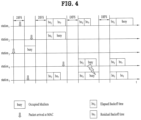
- the STA3 determines whether the medium is in the idle state during the DIFS, and may directly start frame transmission. In the meantime, the remaining STAs monitor whether the medium is in the busy state, and wait for a predetermined time. During the predetermined time, data to be transmitted may occur in each of STA1, STA2, and STAS. If the medium is in the idle state, each STA waits for the DIFS time and then performs countdown of the backoff slot in response to a random backoff count value selected by each STA. The example of FIG. 4 shows that STA2 selects the lowest backoff count value and STA1 selects the highest backoff count value.
- the residual backoff time of STA5 at a frame transmission start time is shorter than the residual backoff time of STA1.
- Each of STA1 and STA5 temporarily stops countdown while STA2 occupies the medium, and waits for a predetermined time. If occupying of the STA2 is finished and the medium re-enters the idle state, each of STA1 and STA5 waits for a predetermined time DIFS, and restarts backoff counting. That is, after the remaining backoff slot as long as the residual backoff time is counted down, frame transmission may start operation. Since the residual backoff time of STA5 is shorter than that of STA1, STA5 starts frame transmission.
- each of STA4 and STA5 increases the CW value two times, and STA4 or STA5 may select a random backoff count value and then perform countdown.
- STA1 waits for a predetermined time while the medium is in the occupied state due to transmission of STA4 and STAS. In this case, if the medium is in the idle state, STA1 waits for the DIFS time, and then starts frame transmission after lapse of the residual backoff time.
- the CSMA/CA mechanism includes not only a physical carrier sensing mechanism in which the AP and/or STA can directly sense the medium, but also a virtual carrier sensing mechanism.
- the virtual carrier sensing mechanism can solve some problems (such as a hidden node problem) encountered in the medium access.
- MAC of the WLAN system can utilize a Network Allocation Vector (NAV).
- NAV Network Allocation Vector
- the AP and/or STA each of which currently uses the medium or has authority to use the medium, may inform another AP and/or another STA for the remaining time in which the medium is available.
- the NAV value may correspond to a reserved time in which the medium will be used by the AP and/or STA configured to transmit the corresponding frame.
- AN STA having received the NAV value may prohibit medium access (or channel access) during the corresponding reserved time.
- NAV may be set according to the value of a 'duration' field of the MAC header of the frame.
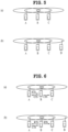
- FIG. 5 is a conceptual diagram illustrating a hidden node and an exposed node.
- FIG. 5(a) exemplarily shows the hidden node.
- STA A communicates with STA B, and STA C has information to be transmitted.
- STA C may determine that the medium is in the idle state when performing carrier sensing before transmitting data to STA B, under the condition that STA A transmits information to STA B. Since transmission of STA A (i.e., occupied medium) may not be detected at the location of STA C, it is determined that the medium is in the idle state. In this case, STA B simultaneously receives information of STA A and information of STA C, resulting in the occurrence of collision.
- STA A may be considered as a hidden node of STA C.
- FIG. 5(b) exemplarily shows an exposed node.
- STA C under the condition that STA B transmits data to STA A, STA C has information to be transmitted to STA D. If STA C performs carrier sensing, it is determined that the medium is occupied due to transmission of STA B. Therefore, although STA C has information to be transmitted to STA D, the medium-occupied state is sensed, such that the STA C must wait for a predetermined time (i.e., standby mode) until the medium is in the idle state.
- a predetermined time i.e., standby mode
- STA C is referred to as an exposed node of STAB.
- FIG. 6 is a conceptual diagram illustrating Request To Send (RTS) and Clear To Send (CTS).
- RTS/CTS short signaling packet
- RTS/CTS between two STAs may be overheard by peripheral STA(s), such that the peripheral STA(s) may consider whether information is communicated between the two STAs. For example, if STA to be used for data transmission transmits the RTS frame to the STA having received data, the STA having received data transmits the CTS frame to peripheral STAs, and may inform the peripheral STAs that the STA is going to receive data.
- FIG. 6(a) exemplarily shows the method for solving problems of the hidden node.
- STA A and STA C are ready to transmit data to STA B. If STA A transmits RTS to STA B, STA B transmits CTS to each of STA A and STA C located in the vicinity of the STA B. As a result, STA C must wait for a predetermined time until STA A and STA B stop data transmission, such that collision is prevented from occurring.
- FIG. 6(b) exemplarily shows the method for solving problems of the exposed node.
- STA C performs overhearing of RTS/CTS transmission between STA A and STA B, such that STA C may determine no collision although it transmits data to another STA (for example, STA D). That is, STA B transmits an RTS to all peripheral STAs, and only STA A having data to be actually transmitted can transmit a CTS.
- STA C receives only the RTS and does not receive the CTS of STA A, such that it can be recognized that STA A is located outside of the carrier sensing range of STA C.
- the WLAN system has to perform channel sensing before STA performs data transmission/reception.
- the operation of always sensing the channel causes persistent power consumption of the STA.
- Continuous maintenance of the Rx state may cause large load to a power-limited STA (i.e., STA operated by a battery). Therefore, if STA maintains the Rx standby mode so as to persistently sense the channel, power is inefficiently consumed without special advantages in terms of WLAN throughput.
- the WLAN system supports a Power Management (PM) mode of the STA.
- PM Power Management
- the PM mode of the STA is classified into an active mode and a Power Save (PS) mode.
- the STA is basically operated in the active mode.
- the STA operating in the active mode maintains an awake state. If the STA is in the awake state, the STA may normally operate such that it can perform frame transmission/reception, channel scanning, or the like.
- STA operating in the PS mode is configured to switch from the doze state to the awake state or vice versa.
- STA operating in the sleep state is operated with minimum power, and the STA does not perform frame transmission/reception and channel scanning.
- the amount of power consumption is reduced in proportion to a specific time in which the STA stays in the sleep state, such that the STA operation time is increased in response to the reduced power consumption.
- it is impossible to transmit or receive the frame in the sleep state such that the STA cannot mandatorily operate for a long period of time.
- the STA operating in the sleep state is switched to the awake state, such that it can transmit/receive the frame in the awake state.
- the sleep-state STA is unable to receive the frame and cannot recognize the presence of a frame to be received.
- STA may need to switch to the awake state according to a specific period in order to recognize the presence or absence of a frame to be transmitted to the STA (or in order to receive a signal indicating the presence of the frame on the assumption that the presence of the frame to be transmitted to the STA is decided).
- the AP may transmit a beacon frame to STAs in a BSS at predetermined intervals.
- the beacon frame may include a traffic indication map (TIM) information element.
- the TIM information element may include information indicating that the AP has buffered traffic for STAs associated therewith and will transmit frames.
- TIM elements include a TIM used to indicate a unitcast frame and a delivery traffic indication map (DTIM) used to indicate a multicast or broadcast frame.
- DTIM delivery traffic indication map
- FIGS. 7 to 9 are conceptual diagrams illustrating detailed operations of the STA having received a Traffic Indication Map (TIM).
- TIM Traffic Indication Map
- STA is switched from the sleep state to the awake state so as to receive the beacon frame including a TIM from the AP.
- STA interprets the received TIM element such that it can recognize the presence or absence of buffered traffic to be transmitted to the STA.
- the STA may transmit the PS-Poll frame for requesting data frame transmission to the AP.
- the AP having received the PS-Poll frame transmitted by the STA may transmit the frame to the STA.
- STA may receive a data frame and then transmit an ACK frame to the AP in response to the received data frame. Thereafter, the STA may reenter the sleep state.
- the AP may operate according to the immediate response scheme, such that the AP receives the PS-Poll frame from the STA and transmits the data frame after lapse of a predetermined time [for example, Short Inter-Frame Space (SIFS)].
- a predetermined time for example, Short Inter-Frame Space (SIFS)
- the AP having received the PS-Poll frame does not prepare a data frame to be transmitted to the STA during the SIFS time, such that the AP may operate according to the deferred response scheme, and as such a detailed description thereof will hereinafter be described with reference to FIG. 8 .
- the STA operations of FIG. 8 in which the STA is switched from the sleep state to the awake state, receives a TIM from the AP, and transmits the PS-Poll frame to the AP through contention are identical to those of FIG. 7 . If the AP having received the PS-Poll frame does not prepare a data frame during the SIFS time, the AP may transmit the ACK frame to the STA instead of transmitting the data frame. If the data frame is prepared after transmission of the ACK frame, the AP may transmit the data frame to the STA after completion of such contending. STA may transmit the ACK frame indicating successful reception of a data frame to the AP, and may be shifted to the sleep state.
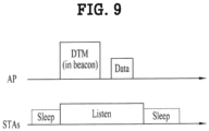
- FIG. 9 shows the exemplary case in which AP transmits DTIM.
- STAs may be switched from the sleep state to the awake state so as to receive the beacon frame including a DTIM element from the AP.
- STAs may recognize that multicast/broadcast frame(s) will be transmitted through the received DTIM.
- AP may directly transmit data (i.e., multicast/broadcast frame) without transmitting/receiving the PS-Poll frame.
- the STAs While STAs continuously maintains the awake state after reception of the beacon frame including the DTIM, the STAs may receive data, and then switch to the sleep state after completion of data reception.
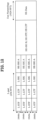
- FIG. 10 is an explanatory diagram of an exemplary frame structure used in an IEEE 802.11 system.
- a PPDU (Physical Layer Protocol Data Unit) frame format may include an STF (Short Training Field), an LTF (Long Training Field), a SIG (SIGNAL) field and a data field.
- the most basic (e.g., non-HT (High Throughput)) PPDU frame format may include only an L-STF (Legacy-STF), an L-LTF (Legacy-LTF), a SIG field and a data field.
- the STF is a signal for signal detection, AGC (Automatic Gain Control), diversity selection, accurate time synchronization, etc.
- the LTF is a signal for channel estimation, frequency error estimation, etc.
- the STF and LTF may be collectively called a PLCP preamble.
- the PLCP preamble may be regarded as a signal for OFDM physical layer synchronization and channel estimation.
- the SIG field may include a RATE field and a LENGTH field.
- the RATE field may include information about modulation and coding rates of data.
- the LENGTH field may include information about the length of data.
- the SIG field may include a parity bit, a SIG TAIL bit, etc.
- the data field may include a SERVICE field, a PSDU (Physical layer Service Data Unit) and a PPDU TAIL bit.
- the data field may also include padding bits as necessary. Some bits of the SERVICE field may be used for synchronization of a descrambler at a receiving end.
- the PSDU corresponds to an MPDU (MAC Protocol Data Unit) defined in the MAC layer and may include data generated/used in a higher layer.
- the PPDU TAIL bit may be used to return an encoder to state 0.
- the padding bits may be used to adjust the length of the data field to a predetermined unit.
- the MPDU is defined depending on various MAC frame formats, and a basic MAC frame includes a MAC header, a frame body and an FCS (Frame Check Sequence).
- the MAC frame may be composed of the MPDU and transmitted/received through PSDU of a data part of the PPDU frame format.
- the MAC header includes a frame control field, a duration/ID field, an address field, etc.
- the frame control field may include control information necessary for frame transmission/reception.
- the duration/ID field may be set to a time to transmit a relevant a relevant frame.
- the duration/ID field included in the MAC header may be set to a 16-bit length (e.g., B0 to B15). Content included in the duration/ID field may depend on frame type and sub-type, whether transmission is performed for a CFP (contention free period), QoS capability of a transmission STA and the like. (i) In a control frame corresponding to a sub-type of PS-Poll, the duration/ID field may include the AID of the transmission STA (e.g., through 14 LSBs) and 2 MSBs may be set to 1.
- the duration/ID field may be set to a fixed value (e.g., 32768).
- the duration/ID field may include a duration value defined per frame type.
- the actual TXOP duration indicated by B0 to B14 may be one of 0 to 32767 and the unit thereof may be microseconds ( ⁇ s).
- B15 can be set to 1 and B0 to B14 can be set to 0.
- B0 to B13 indicate one AID of 1 to 2007.
- the frame control field of the MAC header may include Protocol Version, Type, Subtype, To DS, From DS, More Fragment, Retry, Power Management, More Data, Protected Frame and Order subfields.
- Protocol Version Type, Subtype, To DS, From DS, More Fragment, Retry, Power Management, More Data, Protected Frame and Order subfields.
- FIG. 11 illustrates a CF (contention free)-END frame.
- the CF-END frame is transmitted by a non-DMG (directional multi-gigabit, 11ad) STA for convenience of description.
- the CF-END frame may be transmitted to truncate a TXOP duration. Accordingly, a duration field is set to 0 in the CF-END frame.
- An RA (Receiver Address) field may be set to a broadcast group address.
- a BSSID field may be set to an STA address included in a relevant AP.
- an Individual/Group bit of the BSSID field may be set to 1.
- FIG. 12 illustrates an example of the HE PPDU.
- an HE-SIG A (or HE-SIG1) field follows an L-Part (e.g., L-STF, L-LTF, L-SIG) and is duplicated every 20 MHz like the L-Part.
- the HE-SIG A field includes common control information (e.g., BW, GI length, BSS index, CRC, Tail, etc.) for STAs.
- the HE-SIG A field includes information for decoding the HE PPDU and thus information included in the HE-SIG A field may depend on the format of the HE PPDU (e.g., SU PPDU, MU PPDU, trigger-based PPDU or the like).
- the HE-SIG A field may include at least one of a DL/UL indicator, HE PPDU format indicator, BSS color, TXOP duration, BW (bandwidth), MCS, CP + LTF length, coding information, the number of streams, STBC (e.g., whether STBC is used), transmission beamforming (TxBF) information, CRC and Tail.
- the HE-SIG B field may be omitted.
- the HE-SIG A field may include at least one of a DL/UL indicator, BSS color, TXOP duration, BW, MCS information of a SIG B field, the number of symbols of the SIG B field, the number of HE LTF symbols, indicator indicating whether full band MU-MIMO is used, CP + LTF length, transmission beamforming (TxBF) information, CRC and Tail.
- an HE-SIG A field may include at least one of a format indicator (e.g., indicating the SU PPDU or trigger-based PPDU), BSS color, TXOP duration, BW, CRC and Tail.
- a format indicator e.g., indicating the SU PPDU or trigger-based PPDU
- BSS color e.g., BSS color
- TXOP duration e.g., BW, CRC and Tail.
- FIG. 13 illustrates another example of the HE PPDU.
- the HE-SIG A may include user allocation information, for example, at least one of an STA ID such as a PAID or a GID, allocated resource information and the number of streams (Nsts), in addition to the common control information.
- the HE-SIG B (or HE-SIG2) may be transmitted for each OFDMA allocation.
- the HE-SIG B is identified by an STA through SDM.
- the HE-SIG B may include additional user allocation information, for example, an MCS, coding information, STBC (Space Time Block Code) information and transmission beamforming (TXBF) information.
- FIG. 14 illustrates another example of the HE PPDU.
- the HE-SIG B is transmitted following the HE-SIG A.
- the HE-SIG B may be transmitted through the full band on the basis of numerology of the HE-SIG A.
- the HE-SIG B may include user allocation information, for example, STA AID, resource allocation information (e.g., allocation size), MCS, the number of streams (Nsts), coding, STBC and transmission beamforming (TXBF) information.
- STA AID resource allocation information
- resource allocation information e.g., allocation size
- MCS the number of streams
- Nsts the number of streams
- STBC transmission beamforming
- FIG. 15 illustrates another example of the HE PPDU.
- the HE-SIG B may be duplicated per predetermined unit channel. Referring to FIG. 15 , the HE-SIG B may be duplicated per 20 MHz. For example, the HE-SIG B can be transmitted in such a manner that the same information is duplicated per 20 MHz in 80MHz bandwidth.
- An STA/AP which has received the HE-SIG B duplicated every 20 MHz may accumulate the received HE-SIG B per 20 MHz channel to improve reliability of HE-SIG B reception.
- the gain of accumulated signals is proportional to the number of channels over which the signal is duplicated and transmitted to improve reception performance.
- a duplicated and transmitted signal can have a gain corresponding to 3 dB X (the number of channels) compared to the signal before duplication.
- the duplicated and transmitted HE-SIG B may be transmitted with an increased MCS level depending on the number of channels through which the HE-SIG B is duplicated and transmitted. For example, if MCSO is used for the HE-SIG B transmitted without being duplicated, MCS1 can be used for the HE-SIG B duplicated and transmitted. Since the HE-SIG B can be transmitted with a higher MCS level as the number of channels for duplication increases, HE-SIG B overhead per unit channel can be reduced.
- FIG. 16 illustrates another example of the HE PPDU.
- the HE-SIG B may include independent information per 20 MHz channel.
- the HE-SIG B may be transmitted in a 1x symbol structure like the Legacy part (e.g., L-STF, L-LTF, L-SIG) and HE-SIG A. Meanwhile, a length of "L-STF+L-LTF+L-SIG+HE-SIGA+HE-SIGB" needs to be identical in all channels in a wide bandwidth.
- the HE-SIG B transmitted per 20 MHz channel may include allocation information about the corresponding band, for example, allocation information per user using the corresponding band, user ID, etc. However, the information of the HE-SIG B may vary between bands because the respective bands support different numbers of users and use different resource block configurations. Accordingly, the length of the HE-SIG B may be different for respective channels.
- FIG. 17 illustrates an HE-SIG B padding method by which lengths before HE-STF (e.g., lengths to the HE-SIG B) become identical for respective channels.
- the HE-SIG B may be duplicated by a padding length to align HE-SIG B lengths.
- the HE-SIG B corresponding to a necessary padding length may be padded to the HE-SIG B from the start (or end) of the HE-SIG B.
- one HE-SIG B field can be transmitted when the bandwidth does not exceed 20 MHz.
- 20 MHz channels may respectively transmit one of a first type HE-SIG B (referred to hereinafter as HE-SIG B [1]) and a second type HE-SIG B (referred to hereinafter as HE-SIG B [2]).
- HE-SIG B [1] and HE-SIG B [2] may be alternately transmitted.
- An odd-numbered 20 MHz channel may deliver HE-SIG B [1] and an even-numbered 20 MHz channel may deliver HE-SIG B [2].
- HE-SIG B [1] is transmitted over the first 20 MHz channel and HE-SIG B [2] is transmitted over the second 20 MHz channel.
- HE-SIG B [1] is transmitted over the first 20 MHz channel
- HE-SIG B [2] is transmitted over the second 20 MHz channel
- the same HE-SIG B [1] is duplicated and transmitted over the third 20 MHz channel
- the same HE-SIG B [2] is duplicated and transmitted over the fourth 20 MHz channel.
- the HE-SIG B is transmitted in a similar manner in the case of a 160 MHz bandwidth.
- the HE-SIG B can be duplicated and transmitted as the bandwidth increases.
- a duplicated HE-SIG B may be frequency-hopped by 20 MHz from a 20 MHz channel over which an HE-SIG B of the same type is transmitted and transmitted.
- HE-SIG B [1] and HE-SIG B [2] may have different content. However, HE-SIG-Bs [1] have the same content. Similarly, HE-SIG Bs [2] have the same content.
- HE-SIG B [1] may be configured to include resource allocation information about only odd-numbered 20 MHz channels and HE-SIG B [2] may be configured to include resource allocation information about only even-numbered 20 MHz channels.
- HE-SIG B [1] may include resource allocation information about at least part of even-numbered 20 MHz channels or HE-SIG B [2] may include resource allocation information about at least part of odd-numbered 20 MHz channels.
- the HE-SIG B may include a common field and a user-specific field.
- the common field may precede the user-specific field.
- the common field and the user-specific field may be distinguished in a unit of bit(s) instead of a unit of OFDM symbol(s).
- the common field of the HE-SIG B includes information for all STAs designated to receive PPDUs in a corresponding bandwidth.
- the common field may include resource unit (RU) allocation information.
- All the HE-SIG Bs [1] may have the same content and All the HE-SIG Bs [2] may have the same content.
- the common field of HE-SIG B [1] may include a common block for LL and RL and the common field of HE-SIG B [2] may include a common block for LR and RR.
- the user-specific field of the HE-SIG B may include a plurality of user fields.
- Each user field may include information specific to an individual STA designated to receive PPDUs.
- the user field may include at least one of an STA ID, MCS per STA, the number of streams (Nsts), coding (e.g., indication of use of LDPC), DCM indicator and transmission beamforming information.
- the information of the user field is not limited thereto.
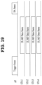
- FIG. 19 is an explanatory diagram of an uplink multi-user transmission situation according to an embodiment of the present invention.
- an 802.11ax system may employ UL MU transmission.
- UL MU transmission may be started when an AP transmits a trigger frame to a plurality of STAs (e.g., STA1 to STA4), as illustrated in FIG. 19 .
- the trigger frame may include UL MU allocation information.
- the UL MU allocation information may include at least one of resource position and size, STA IDs or reception STA addresses, MCS and MU type (MIMO, OFDMA, etc.).
- the trigger frame may include at least one of (i) a UL MU frame duration, (ii) the number of allocations (N) and (iii) information per allocation.
- the information per allocation may include information per user (Per user Info).
- the information per allocation may include at least one of an AID (AIDs corresponding to the number of STAs are added in the case of MU), power adjustment information, resource (or tone) allocation information (e.g., bitmap), MCS, the number of streams (Nsts), STBC, coding and transmission beamforming information.
- AID AIDs corresponding to the number of STAs are added in the case of MU
- resource (or tone) allocation information e.g., bitmap
- MCS the number of streams
- STBC coding and transmission beamforming information.
- the AP may acquire TXOP to transmit the trigger frame through a contention procedure to access media. Accordingly, the STAs may transmit UL data frames in a format indicated by the AP after SIFS of the trigger frame. It is assumed that the AP according to an embodiment of the present invention sends an acknowledgement response to the UL data frames through a block ACK (BA) frame.
- BA block ACK
- FIG. 20 illustrates a trigger frame format according to an embodiment.
- the trigger frame may include at least one of a frame control field, a duration field, an RA (recipient STA address) field, a TA (transmitting STA address) field, a common information field, one or more Per User Info fields and FCS (Frame Check Sum).
- the RA field indicates the address or ID of a recipient STA and may be omitted according to embodiments.
- the TA field indicates the address of a transmitting STA.
- the common information field may include at least one of a length subfield, a cascade indication subfield, an HE-SIG A information subfield, a CP/LTF type subfield, a trigger type subfield and a trigger-dependent common information subfield.
- the length subfield indicates the L-SIG length of a UL MU PPDU.
- the cascade indication indicates whether there is transmission of a subsequent trigger frame following the current trigger frame.
- the HE-SIG A information subfield indicates content to be included in the HE-SIG A of the UL MU PPDU.
- the CP/LTF type subfield indicates a CP and HE LTF type included in the UL MU PPDU.
- the trigger type subfield indicates the type of the trigger frame.
- the trigger frame may include common information specific to the type and information per user (Per User Info) specific to the type.
- the trigger type may be set to one of a basic trigger type (e.g., type 0), beamforming report poll trigger type (e.g., type 1), MU-BAR (Multi-user Block Ack Request) type (e.g., type 2) and MU-RTS (multi-user ready to send) type (e.g., type 3).
- the trigger type is not limited thereto.
- the trigger-dependent common information subfield may include a GCR (Groupcast with Retries) indicator and a GCR address.
- the Per User Info field may include at least one of a user ID subfield, an RU allocation subfield, a coding type subfield, an MCS subfield, a DCM (dual sub-carrier modulation) subfield, an SS (spatial stream) allocation subfield and a trigger dependent Per User Info subfield.
- the user ID subfield indicates the AID of an STA which will use a corresponding resource unit to transmit MPDU of the UL MU PPDU.
- the RU allocation subfield indicates a resource unit used for the STA to transmit the UL MU PPDU.
- the coding type subfield indicates the coding type of the UL MU PPDU transmitted by the STA.
- the MCS subfield indicates the MCS of the UL MU PPDU transmitted by the STA.
- the DCM subfield indicates information about double carrier modulation of the UL MU PPDU transmitted by the STA.
- the SS allocation subfield indicates information about spatial streams of the UL MU PPDU transmitted by the STA.
- the trigger-dependent Per User Info subfield may include BAR control and BAR information.
- NAV Network Allocation Vector
- a NAV may be understood as a timer for protecting TXOP of a transmitting STA (e.g., TXOP holder).
- An STA may not perform channel access during a period in which a NAV configured in the STA is valid so as to protect TXOP of other STAs.
- a current non-DMG STA supports one NAV.
- An STA which has received a valid frame can update the NAV through the duration field of the PSDU (e.g., the duration field of the MAC header).
- the STA does not update the NAV.
- a duration indicated by the duration field of the received frame is greater than the current NAV value of the STA, the STA updates the NAV through the duration of the received frame.
- FIG. 21 illustrates an example of NAV setting.
- a source STA transmits an RTS frame and a destination STA transmits CTS frame.
- the destination STA designated as a recipient through the RTS frame does not set a NAV.
- Some of other STAs may receive the RTS frame and set NAVs and others may receive the CTS frame and set NAVs.
- the CTS frame (e.g., PHY-RXSTART.indication primitive) is not received within a predetermined period from a timing when the RTS frame is received (e.g., PHY-RXEND.indication primitive for which MAC corresponds to the RTS frame is received)
- STAs which have set or updated NAVs through the RTS frame can reset the NAVs (e.g., 0).
- the predetermined period may be (2*aSIFSTime + CTS_Time + aRxPHYStartDelay + 2*aSlotTime).
- the CTS_Time may be calculated on the basis of the CTS frame length indicated by the RTS frame and a data rate.
- NAV setting/resetting/update may be performed on the basis of duration fields of various frames, for example, non-HT PPDU, HT PPDU, VHT PPDU and HE PPDU (e.g., the duration field of the MAC header of the MAC frame). For example, if the RA field of the received MAC frame does not correspond to the address of an STA (e.g., MAC address), the STA may set/reset/update the NAV.
- STA e.g., MAC address
- FIG. 22 illustrates an example of TXOP truncation.
- a TXOP holder STA may indicate to truncate TXOP by transmitting a CF-END frame.
- AN STA can reset the NAV (e.g., set the NAV to 0) upon reception of a CF-END frame or CF-END+CF-ACK frame.
- the STA can transmit a CF-END frame.
- the STA can explicitly indicate completion of TXOP thereof through transmission of the CF-END frame.
- the CF-END frame may be transmitted by a TXOP holder.
- a non-AP STA that is not a TXOP holder cannot transmit the CF-END frame.
- a STA which has received the CF-END frame resets the NAV at a time when a PPDU included in the CF-END frame is ended.
- an STA that has accessed a medium transmits a sequence (e.g., RTS/CTS) for NAV setting.
- a sequence e.g., RTS/CTS
- a TXOP holder (or TXOP initiator) and a TXOP responder transmit and receive PPDUs (e.g., initiator sequence).
- the TXOP holder truncates a TXOP by transmitting a CF-END frame when there is no data to be transmitted within the TXOP.
- a TXOP duration is set through the duration field of the MAC header in the current wireless LAN system. That is, a TXOP holder (e.g., Tx STA) and a TXOP responder (e.g., Rx STA) include whole TXOP information necessary for transmission and reception of frames in duration fields of frames transmitted and received therebetween and transmit the frames. Third party STAs other than the TXOP holder and the TXOP responder check the duration fields of frames exchanged between the TXOP holder and the TXOP responder and sets/updates NAVs to defer use of channels until NAV periods.
- Tx STA e.g., Tx STA
- Rx STA e.g., Rx STA
- Third party STAs other than the TXOP holder and the TXOP responder check the duration fields of frames exchanged between the TXOP holder and the TXOP responder and sets/updates NAVs to defer use of channels until NAV periods.
- the third party STAs cannot decode an MPDU included in a UL MU PPDU even when they receive the UL MU PPDU if the UL MU PPDU does not include the HE-SIG B. If the third party STAs cannot decode the MPDU, the third party STAs cannot acquire TXOP duration information (e.g., duration field) included in the MAC header of the MPDU. Accordingly, it is difficult to correctly perform NAV setting/update.
- TXOP duration information e.g., duration field
- the third party STAs cannot decode a MAC frame (e.g., an MPDU in the HE PPDU corresponding to other STAS) transmitted and received by other STAs. Accordingly, the third party STAs cannot acquire TXOP information in this case.
- a MAC frame e.g., an MPDU in the HE PPDU corresponding to other STAS
- an STA includes TXOP duration information in the HE-SIG A and transmits the HE-SIG A.
- 15 bits e.g., B0 to B14
- duration information may indicate duration information of up to 32.7 ms (0 to 32767 us).
- an 11ax third party STA can correctly set/update a NAV.
- HE-SIG A signaling overhead excessively increases.
- the HE-SIG A for common control information transmission in the physical layer is a compactly designed field, and thus an increase of 15 bits in the HE-SIG A corresponds to relatively large signaling overhead.
- an embodiment of the present invention proposes an efficient TXOP duration indication method for minimizing HE-SIG A overhead.
- an embodiment of the present invention proposes frame transmission and reception operations based on a TXOP duration newly defined in the HE-SIG A.
- the duration field included in the MAC header may be referred to as a MAC duration for convenience.
- TXOP duration information is included in the HE SIG A and transmitted in the following description, the scope of the present invention is not limited thereto and the TXOP duration information may be transmitted through other parts (e.g., L-SIG, HE-SIG B, HE-SIG C, ..., and part of A-MPDU or MPDU).
- the TXOP duration can be transmitted through common information (e.g., common part) of the HE-SIG B or a SIG B contents part (e.g., Per user Info) transmitted at the first (or end) part of the HE-SIG B.
- a value set to the NAV of a third party STA can be interpreted as a TXOP duration for a TXOP holder/responder.
- a duration field value is a TXOP for frame transmission and reception in view of the TXOP holder/responder.
- the duration field value refers to a NAV value in view of the third party STA.
- a NAV setting/update operation of the third party STA may be referred to as a TXOP setting/update operation because the NAV setting/update operation sets a NAV corresponding to a TXOP for the TXOP holder/responder.
- TXOP duration may be simply referred to as “duration” or "TXOP".
- the TXOP duration may be used to indicate a field (e.g., the TXOP duration field of the HE-SIG A) in a frame or to indicate an actual TXOP duration value.
- the TXOP duration may be set to 2 N -1 (or 2 N ). It is assumed that the TXOP duration is set to 2 N -1 for convenience.
- the value N can be transmitted in the TXOP duration field of the HE-SIG A.
- N when N is 4 bits, N has a value in the range of 0 to 15. Accordingly, the TXOP duration indicated through N having a size of 4 bits may have a value in the range of 0 to 32,767 ⁇ s.
- the TXOP duration may be set to X Y -1 (or X Y ). It is assumed that the TXOP duration is set to X Y -1.
- AN STA can transmit values X and Y through the TXOP duration field (e.g., in the HE-SIG A).
- n bits (first n bits) of the K bits may indicate the value X and m bits thereof (e.g., m bits at the end) may indicate the value Y.
- the n bits may be n MSBs or n LSBs and the m bits may be m LSBs or m MSBs.
- the values K, m and n can be set in various manners.
- an (X, Y) combination that minimizes X Y -1, from among (X, Y) combinations satisfying X Y -1 ⁇ P ms (e.g., 5ms), may be used to indicate a maximum TXOP duration value and other (X, Y) combinations may not be used.
- This example is one of methods of indicating the TXOP duration through Z * X Y -1 and thus X, Y and/or Z may be changed in various manners.
- Table 3 illustrates a case in which the TXOP duration field is set to 4 bits.
- the TXOP duration exponentially increases in the range of 32 ⁇ s to 512 ⁇ s (or 1,024 ⁇ s) and increases by 512 ⁇ s (approximately 0.5 ms) after 512 ⁇ s (or 1,024 ⁇ s).
- TXOP Duration field Actual value (unit: us) 0 0 1 32 2 64 3 128 4 256 5 512 6 1024 7 1536 8 2048 9 2560 10 3072 11 3584 12 4096 13 4608 14 5120 15 5632
- the TXOP duration can be set through an X-bit scaling factor and a Y-bit duration value.
- the TXOP duration can be set on the basis of Scaling factor (X bits) * Duration (Y bits).
- TXOP duration Scaling factor (X bits) * Duration (Y bits).
- TXOP Duration field Actual value (unit: us) TXOP Duration field Actualvalue (unit: us) 0 16 32 512 1 32 33 1024 2 48 34 1536 3 64 35 2048 4 80 36 2560 5 96 37 3072 6 112 38 3584 7 128 39 4096 8 144 40 4608 9 160 41 5120 10 176 42 5632 11 192 43 6144 12 208 44 6656 13 224 45 7168 14 240 46 7680 15 256 47 8192 16 272 48 8704 17 288 49 9216 18 304 50 9728 19 320 51 10240 20 336 52 10752 21 352 53 11264 22 368 54 11776 23 384 55 12288 24 400 56 12800 25 416 57 13312 20 432 58 13824 27 448 59 14336 28 464 60 14848 29 480 61 15360 30 496 62 15872 31 512 63 16384
- the duration of UL MU BA is set to 422.4 ⁇ s corresponding to the sum of 48 ⁇ s for the preamble and 374.4 ⁇ s for the MAC frame.
- the TXOP duration needs to support small packets having a small granularity (e.g., 16 or 32 ⁇ s).
- a method for supporting such small-capacity packets a method of using multiple granularities (e.g., small and large granularities) for TXOP may be considered.
- multiple units can be used for the TXOP duration.
- the number of multiple units may be 2 (or 4), the number of multiple units is not limited thereto. If the number of units is 2, respective units may be referred to as a small unit and a large unit for convenience.
- the actual sizes of the small unit and the large unit may depend on the size of the TXOP duration field (e.g., 5, 6 or 7 bits).
- the small unit can be used to indicate a duration of less than 512 ⁇ s and the large unit can be used to indicate a duration in the range of 512 ⁇ s to the maximum TXOP duration value (e.g., approximately 8 ms).
- the small unit can be used for the above-described UL MU BA (e.g., having a duration of approximately 400 ⁇ s) of the lowest data rate.
- B0 B1 ⁇ B4 TXOP duration range Unit TXOP duration value 0 0000 ⁇ 1111 0 us ⁇ 480 us 32 us (32 * value of (B1 ⁇ B4)) us 1 0000 ⁇ 1111 512 us ⁇ 8192 us 512 us (512+ 512 * value of (B1 ⁇ B4)) us
- the STA may acquire a TXOP duration value from a predefined lookup table.
- the STA may use a lookup table such as Table 23 instead of calculating a TXOP duration value every time.
- Table 23 shows results calculated according to the above-described TXOP duration value calculation method.
- the unit of 32 ⁇ s is applied to TXOP indices 0 and 1 and the unit of 512 ⁇ s is applied to TXOP indices 16 and 17.
- TXOP duration field 6 bits (e.g., B0 ⁇ B5)
- small unit 16 ⁇ s
- large unit 256 ⁇ s (option 2-1 of Table 20).
- B0 B1 ⁇ B5 TXOP duration range Unit TXOP duration value 0 00000 ⁇ 11111 0 us ⁇ 496 us 16 us (16 * value of (B1 ⁇ B5)) us 1 00000 ⁇ 11111 512 us ⁇ 8448 us 256 us (512+ 256 * value of (B1 ⁇ B5)) us
- B0 B1 ⁇ B6 TXOP duration range Unit TXOP duration value 0 000000 ⁇ 111111 0 us ⁇ 504 us 8 us (8 * value of (B1 ⁇ B6)) us 1 000000 ⁇ 111111 512 us ⁇ 8576 us 128 us (512+ 128 * value of (B1 ⁇ B6)) us
- the unit of 8 ⁇ s is applied to TXOP indices 0 and 32 and the unit of 128 ⁇ s is applied to TXOP indices 64 and 96.
- TXOP duration value 00 00000 ⁇ 11111 0 us ⁇ 248 us 8 us (8 * value of (B2 ⁇ B6)) us 01 00000 ⁇ 11111 256 us ⁇ 506 us (256+ 8 * value of (B2 ⁇ B6)) us 10 00000 ⁇ 11111 512 us ⁇ 760 us (512+ 8 * value of (B2 ⁇ B6)) us 11 00000 ⁇ 11111 768 us ⁇ 8704 us 256 us (768+ 256 * value of (B2 ⁇ B6)) us
- the STA may acquire a TXOP duration value from a predefined lookup table.
- a lookup table corresponding to Table 30 is omitted for convenience.
- B0 B1 ⁇ B6 TXOP duration range Unit TXOP duration value 0 000000 ⁇ 111111 0 us ⁇ 1008 us 16 us (16 * value of (B1 ⁇ B6)) us 1 000000 ⁇ 111111 1024 us ⁇ 12616 us 256 us (1024+ 256 * value of (B1 ⁇ B6)) us
- the STA may acquire a TXOP duration value from a predefined lookup table.
- a lookup table corresponding to Table 31 is omitted for convenience.
- Table 32 shows throughput and gains with respect to the above-described examples.
- 20 MHz channels on 5 GHz and 2Tx-2Rx are assumed.
- a buffer state is a full buffer state, TXOP is 2 ms and RTS is in an off state.
- the left column of Table 32 represents a case in which the CF-END frame is not used and the right column of Table 32 represents a case in which the CF-END frame is used.
- An STA (e.g., a TXOP holder/responder) transmitting frames needs to determine and calculate a TXOP duration value that the STA intends to signal through the TXOP duration field of the HE-SIG A.
- the STA can determine a TXOP duration value (e.g., a value indicated by the TXOP duration field of HE-SIG A) on the basis of the duration of a MAC header included in a frame that the STA transmits (e.g., the duration field of the MAC header of MPDU).
- FIG. 25 illustrates a method of setting a TXOP duration value according to an embodiment.
- MAC duration value D.
- ceiling (A) represents the smallest integer from among integers equal to or greater than A.
- the TXOP duration value is set to be greater than MAC duration value D.
- TXOP duration value MAC duration value D is satisfied when the MAC duration value D is a multiple of the granularity and TXOP duration value > MAC duration value D is satisfied in other cases.
- TXOP duration field value TXOP index
- TXOP duration field value TXOP index
- the TXOP duration field of HE-SIG A can set a TXOP duration on the basis of a relatively large granularity.
- the duration field included in the MAC header can be indicated based on a 1 ⁇ s granularity
- the TXOP duration field of HE-SIG A can be set to indicate a TXOP duration value on the basis of a granularity greater than the granularity of 1 ⁇ s.
- the TXOP duration When the TXOP duration is set by the TXOP duration field of HE-SIG A on the basis of a relatively large granularity, the TXOP duration can be set to a time longer than the time actually used for frame transmission. Accordingly, other STAs may set incorrect NAVs on the basis of HE-SIG A and thus cannot use channels for a specific time, and channel efficiency may be deteriorated.
- TXOP holder/responder transmits the last frame (e.g., ACK, Block ACK, Multi-STA BA) during a TXOP period
- the TXOP holder/responder may include information indicating early termination of TXOP in the last frame and transmit the last frame.
- Early TXOP termination may be represented as TXOP truncation or simply as (early) termination/truncation. A description will be given of TXOP termination methods.
- a TXOP holder/responder can transmit the last frame during a TXOP period and then terminate TXOP by transmitting a CF-END frame.
- STAs that have read both HE-SIG A and frame content set TXOP through duration information of the frame content (e.g., MAC header).
- the STAs that have read both HE-SIG A and frame content store the duration information included in HE-SIG A.
- the STAs determine a final TXOP duration on the basis of the duration of the MAC header (or duration of the content) instead of the duration of HE-SIG A to update NAVs.
- STAs that read only HE-SIG A update NAVs on the basis of the TXOP duration included in HE-SIG A.
- a problem that a TXOP duration longer than the actual TXOP duration of the MAC header is set may be generated.
- the STAs update TXOP through TXOP duration information included in HE-SIG A/B or the MAC header (e.g., NAV update) and can terminate TXOP at a corresponding time when the early termination indicator (or TXOP update indicator) is set to 1.
- TXOP termination may be performed on the basis of a BSS color.
- an STA e.g., third party
- the STA e.g., third party
- the STA checks a BSS color included in a frame. If the BSS color indicates other BSSs, the STA (e.g., third party) does not terminate TOXP even when the frame indicates TXOP termination. Accordingly, the STA (e.g., third party) can terminate/truncate TXOP only when a frame of the BSS thereof indicates TXOP termination (e.g., explicit indication or implicit indication in which duration is set to 0). However, loss of access opportunity of the STA for other BSSs may occur.
- an STA e.g., a TXOP holder/responder
- the STA can necessarily include TXOP termination/truncation information in the last frame and transmit the last frame.
- TXOP can be set because TXOP is set through the duration of the MAC header.
- the TXOP duration of HE-SIG may be overwritten by the duration of the MAC header.
- an STA may indicate early termination/truncation of TXOP by setting the duration field value of the last frame to a specific value (e.g., setting the duration field value to 0 or setting all bits to 1) instead of using an explicit TXOP termination indicator.
- a specific value e.g., setting the duration field value to 0 or setting all bits to 1
- an STA e.g., third party
- NAV update is performed only when a TXOP duration value of a received frame exceeds a NAV value currently set to an STA (e.g., third party).
- STA e.g., third party
- NAV update needs to be performed even when the TXOP duration value of the received frame is less than the NAV value currently set to an STA.
- the STA may update the NAV with a TXOP duration less than the NAV value currently set thereto on the basis of the aforementioned TXOP truncation/termination/update indicator.
- NAV update with a TXOP duration less than the currently set NAV value may be set to be performed only on the basis of a TXOP termination/update indicator included in myBSS frame.
- the STA may set and maintain a NAV per BSS color.
- the STA can truncate the TXOP of the NAV corresponding to a BSS color indicated by a frame indicating TXOP truncation upon reception of the frame.
- An operation for TXOP power reduction may be defined. For example, feasibility of NAV update is indicated, an STA (e.g., third party) maintains a wake-up state. If no NAV update is indicated, the STA can switch to a power saving (PS) mode.
- an STA e.g., a TXOP holder/responder
- an STA that sets a TXOP may include information about whether NAV update will be performed in a frame and transmit the frame.
- the STA (e.g., third party) may switch to the PS mode only when a received frame is myBSS frame and indicates switching to the PS mode. (e.g., indicates no NAV update).
- the STA may not instruct the STA (e.g., third party) to switch to the PS mode when indicating TXOP/NAV update through frame transmission and may instruct the STA (e.g., third party) to switch to the PS mode only when there is no NAV update.
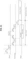
- FIG. 26 illustrates a frame transmission (e.g., TXOP management) and NAV management (e.g., frame reception) method according to an embodiment of the present invention. Description of redundant parts in the above description and the present embodiment will be omitted. It is assumed that STA 1 and STA 3 are TXOP holder/responder STAs and STA 2 is a third party STA. STA 1, STA 2 and STA 3 may be AP or non-AP STAs.
- STA 1 sets a first duration field (e.g., TXOP duration field) included in an HE-SIG A field.
- the first duration field may be set to indicate a TXOP (transmission opportunity value) using a smaller number of bits than that of a second duration field (e.g., MAC duration field) included in a MAC header.
- a granularity of a time unit used for indicating a TXOP value in the first duration field may be set to differ from a granularity (e.g., 1 ⁇ s) of a time unit used in the second duration field of the MAC header.
- the second duration field may be set to 15 bits.
- the granularity used in the first duration field may be set to an integer multiple of the granularity used in the second duration field.
- the granularity used in the first duration field may vary depending on a TXOP value to be indicated through the first duration field.
- the first duration field may include at least one bit (e.g., MSB) indicating a granularity determined according to a TXOP value.
- the remaining bits of the first duration field may indicate the number of time units included in a TXOP value based on the granularity indicated by the at least one bit.
- the first duration field may be set to 5, 6 or 7 bits and the MSB (most significant bit) of the first duration field may be used to indicate a granularity.
- the first duration field can be set to 5 bits and the granularity indicated by the MSB can be one of 32 ⁇ s and 512 ⁇ s.
- the first duration field can be set to 6 bits and the granularity indicated by the MSB can be one of 16 ⁇ s and 256 ⁇ s.
- the first duration field can be set to 7 bits and the granularity indicated by the MSB can be one of 8 ⁇ s and 128 ⁇ s.
- Both the TXOP value indicated by the first duration field and the TXOP value indicated by the second duration field may be set for transmission of the same frame.
- the TXOP value indicated by the first duration field can be calculated on the basis of the TXOP value indicated by the second duration field.
- the TXOP value indicated by the first duration field may be determined to be greater than or equals to the TXOP value indicated by the second duration field.
- STA 1 transmits frame 1 including an HE-SIG field and a MAC header (S2601).
- STA 3 is designated as a receiver of frame 1 for convenience of description.
- a receiver address field of frame 1 transmitted by STA 1 is set to the address of STA 3 (e.g., the MAC address or AID of STA 3).
- STA 1/STA 3 are TXOP holders/responders and STA 2 is a third party STA.
- STA 2 receives (or detects) frame 1 transmitted form STA 1 to STA 3 (S2615).
- STA 2 may perform NAV management on the basis of one of the first duration field included in the HE-SIG A field and the second duration field included in the MAC header (S2615).
- An STA performing NAV management can perform NAV management on the basis of the second duration field (e.g., MAC header) upon successful MAC header decoding and perform NAV management on the basis of the first duration field (e.g., HE-SIG A) upon MAC header decoding failure.
- the first duration field e.g., HE-SIG A
- second STA 2 sets a NAV on the basis of the first duration field (e.g., HE-SIG A) for convenience.
- STA 3 Upon reception of frame 1, STA 3 transmits frame 2 including an HE-SIG A and a MAC header to STA 1 (S2620). STA 2 can detect (or receive) frame 2 and update or reset a NAV on the basis of frame 2(S2625).
- FIG. 27 is an explanatory diagram of apparatuses for implementing the aforementioned method.
- a wireless device 800 and a wireless device 850 in FIG. 27 may correspond to the aforementioned STA/AP 1 and STA/AP 2, respectively.
- the STA 800 may include a processor 810, a memory 820, and a transceiver 830 and the AP 850 may include a processor 860, a memory 870, and a transceiver 860.
- the transceivers 830 and 880 may transmit/receive a wireless signal and may be implemented in a physical layer of IEEE 802.11/3GPP.
- the processors 810 and 860 are implemented in a physical layer and/or a MAC layer and are connected to the transceivers 830 and 880.
- the processors 810 and 860 may perform the above-described UL MU scheduling procedure.
- the processors 810 and 860 and/or the transceivers 830 and 880 may include an Application-Specific Integrated Circuit (ASIC), a chipset, a logical circuit, and/or a data processor.
- the memories 820 and 870 may include a Read-Only Memory (ROM), a Random Access Memory (RAM), a flash memory, a memory card, a storage medium, and/or a storage unit. If an example is performed by software, the above-described method may be executed in the form of a module (e.g., a process or a function) performing the above-described function.
- the module may be stored in the memories 820 and 870 and executed by the processors 810 and 860.
- the memories 820 and 870 may be located at the interior or exterior of the processors 810 and 860 and may be connected to the processors 810 and 860 via known means.
Landscapes
- Engineering & Computer Science (AREA)
- Computer Networks & Wireless Communication (AREA)
- Signal Processing (AREA)
- Mobile Radio Communication Systems (AREA)
Priority Applications (2)
| Application Number | Priority Date | Filing Date | Title |
|---|---|---|---|
| SI201631753T SI4075911T1 (sl) | 2015-05-13 | 2016-05-13 | Upravljanje vektorja omrežne alokacije |
| EP23201212.0A EP4280808A3 (en) | 2015-05-13 | 2016-05-13 | Network allocation vector management |
Applications Claiming Priority (11)
| Application Number | Priority Date | Filing Date | Title |
|---|---|---|---|
| US201562160614P | 2015-05-13 | 2015-05-13 | |
| US201562163984P | 2015-05-20 | 2015-05-20 | |
| US201562259078P | 2015-11-24 | 2015-11-24 | |
| US201662276246P | 2016-01-08 | 2016-01-08 | |
| US201662294310P | 2016-02-12 | 2016-02-12 | |
| US201662297938P | 2016-02-21 | 2016-02-21 | |
| US201662302202P | 2016-03-02 | 2016-03-02 | |
| US201662304304P | 2016-03-06 | 2016-03-06 | |
| EP16793036.1A EP3297359B1 (en) | 2015-05-13 | 2016-05-13 | Method for transmitting or receiving frame in wireless lan system and apparatus therefor |
| PCT/KR2016/005097 WO2016182390A1 (ko) | 2015-05-13 | 2016-05-13 | 무선랜 시스템에서 프레임을 송수신하는 방법 및 이를 위한 장치 |
| EP20208303.6A EP3799507B1 (en) | 2015-05-13 | 2016-05-13 | Method for transmitting or receiving frame in wireless lan system and apparatus therefor |
Related Parent Applications (3)
| Application Number | Title | Priority Date | Filing Date |
|---|---|---|---|
| EP16793036.1A Division EP3297359B1 (en) | 2015-05-13 | 2016-05-13 | Method for transmitting or receiving frame in wireless lan system and apparatus therefor |
| EP20208303.6A Division-Into EP3799507B1 (en) | 2015-05-13 | 2016-05-13 | Method for transmitting or receiving frame in wireless lan system and apparatus therefor |
| EP20208303.6A Division EP3799507B1 (en) | 2015-05-13 | 2016-05-13 | Method for transmitting or receiving frame in wireless lan system and apparatus therefor |
Related Child Applications (1)
| Application Number | Title | Priority Date | Filing Date |
|---|---|---|---|
| EP23201212.0A Division EP4280808A3 (en) | 2015-05-13 | 2016-05-13 | Network allocation vector management |
Publications (2)
| Publication Number | Publication Date |
|---|---|
| EP4075911A1 EP4075911A1 (en) | 2022-10-19 |
| EP4075911B1 true EP4075911B1 (en) | 2023-10-04 |
Family
ID=57248248
Family Applications (4)
| Application Number | Title | Priority Date | Filing Date |
|---|---|---|---|
| EP22177328.6A Active EP4075911B1 (en) | 2015-05-13 | 2016-05-13 | Network allocation vector management |
| EP16793036.1A Active EP3297359B1 (en) | 2015-05-13 | 2016-05-13 | Method for transmitting or receiving frame in wireless lan system and apparatus therefor |
| EP20208303.6A Active EP3799507B1 (en) | 2015-05-13 | 2016-05-13 | Method for transmitting or receiving frame in wireless lan system and apparatus therefor |
| EP23201212.0A Pending EP4280808A3 (en) | 2015-05-13 | 2016-05-13 | Network allocation vector management |
Family Applications After (3)
| Application Number | Title | Priority Date | Filing Date |
|---|---|---|---|
| EP16793036.1A Active EP3297359B1 (en) | 2015-05-13 | 2016-05-13 | Method for transmitting or receiving frame in wireless lan system and apparatus therefor |
| EP20208303.6A Active EP3799507B1 (en) | 2015-05-13 | 2016-05-13 | Method for transmitting or receiving frame in wireless lan system and apparatus therefor |
| EP23201212.0A Pending EP4280808A3 (en) | 2015-05-13 | 2016-05-13 | Network allocation vector management |
Country Status (7)
| Country | Link |
|---|---|
| US (10) | US10154482B2 (pl) |
| EP (4) | EP4075911B1 (pl) |
| ES (3) | ES2843534T3 (pl) |
| HU (2) | HUE064491T2 (pl) |
| PL (2) | PL3799507T3 (pl) |
| SI (2) | SI4075911T1 (pl) |
| WO (1) | WO2016182390A1 (pl) |
Families Citing this family (28)
| Publication number | Priority date | Publication date | Assignee | Title |
|---|---|---|---|---|
| US9955469B2 (en) * | 2015-02-27 | 2018-04-24 | Intel Corporation | Joint encoding of wireless communication allocation information |
| EP4075911B1 (en) | 2015-05-13 | 2023-10-04 | LG Electronics Inc. | Network allocation vector management |
| CN107925536B (zh) * | 2015-07-06 | 2021-10-29 | 瑞典爱立信有限公司 | 用于无线系统中数据传送的资源分配 |
| CN106550479B (zh) * | 2015-09-17 | 2021-11-05 | 中兴通讯股份有限公司 | 一种信道接入方法、接入点、站点 |
| CN113365368B (zh) * | 2015-09-28 | 2024-06-07 | 纽瑞科姆有限公司 | 用于phy报头中的txop持续时间字段的装置和方法 |
| US10153820B2 (en) | 2015-11-25 | 2018-12-11 | Newracom, Inc. | Receiver address field for multi-user transmissions in WLAN systems |
| US10200989B2 (en) * | 2016-01-13 | 2019-02-05 | Intel IP Corporation | Network allocation vector settings for multi-user operation |
| EP3986079B1 (en) | 2016-01-14 | 2023-11-22 | Huawei Technologies Co., Ltd. | Data transmission method and apparatus in wlan |
| WO2017136009A1 (en) * | 2016-02-04 | 2017-08-10 | Intel IP Corporation | CROSS TRANSMISSION OPPORTUNITY (TxOP) SCHEDULING |
| KR20180132608A (ko) * | 2016-04-13 | 2018-12-12 | 소니 주식회사 | 통신 장치, 통신 방법 및 프로그램 |
| US10517021B2 (en) | 2016-06-30 | 2019-12-24 | Evolve Cellular Inc. | Long term evolution-primary WiFi (LTE-PW) |
| US10439687B2 (en) * | 2016-07-18 | 2019-10-08 | Intel IP Corporation | Transmission opportunity (TXOP) duration field disable setting in high efficiency signal A (HE-SIG-A) |
| US10863539B2 (en) * | 2016-09-22 | 2020-12-08 | Qualcomm Incorporated | Transmission opportunity truncation |
| US10652889B2 (en) | 2016-11-02 | 2020-05-12 | Qualcomm Incorporated | Wireless communication between wideband ENB and narrowband UE |
| KR102914037B1 (ko) * | 2017-02-22 | 2026-01-16 | 삼성전자주식회사 | 무선 통신 시스템에서 무선 주파수 경로를 공유하기 위한 장치 및 방법 |
| US11160064B2 (en) * | 2018-02-16 | 2021-10-26 | Convida Wireless, Llc | Communications device, infrastructure equipment, wireless communications systems and methods |
| US11490332B2 (en) | 2018-07-12 | 2022-11-01 | Telefonaktiebolaget Lm Ericsson (Publ) | Multiplexing of wake-up signals |
| EP3909139A1 (en) * | 2019-01-11 | 2021-11-17 | Nokia Technologies Oy | Cooperative beamforming in wireless network |
| JP7292079B2 (ja) * | 2019-03-27 | 2023-06-16 | キヤノン株式会社 | 通信装置、制御方法、および、プログラム |
| US11350431B2 (en) * | 2019-06-21 | 2022-05-31 | Qualcomm Incorporated | Selective adjustment of packet durations |
| SG10202000280YA (en) * | 2020-01-10 | 2021-08-30 | Panasonic Ip Corp America | Communication apparatus and communication method for multi-link secured retransmissions |
| US11323918B2 (en) * | 2020-01-24 | 2022-05-03 | Cisco Technology, Inc. | Switch and backhaul capacity-based radio resource management |
| WO2021175448A1 (en) * | 2020-03-06 | 2021-09-10 | Telefonaktiebolaget Lm Ericsson (Publ) | Control of uplink wireless transmissions in shared txop |
| WO2022084341A1 (en) * | 2020-10-20 | 2022-04-28 | Canon Kabushiki Kaisha | Provision period management for ensuring a low latency service in a bss |
| JP7746690B2 (ja) * | 2021-05-21 | 2025-10-01 | Smc株式会社 | リモート無線装置及びリモート無線装置の通信方法 |
| CN115707121A (zh) * | 2021-08-06 | 2023-02-17 | 华为技术有限公司 | 通信方法、通信设备和计算机可读存储介质 |
| WO2024005792A1 (en) * | 2022-06-28 | 2024-01-04 | Intel Corporation | Early termination of physical layer convergence protocol data unit |
| US20250274976A1 (en) * | 2024-02-26 | 2025-08-28 | Qualcomm Incorporated | Medium protection for shared access points in coordinated time division multiple access |
Family Cites Families (26)
| Publication number | Priority date | Publication date | Assignee | Title |
|---|---|---|---|---|
| US8620989B2 (en) * | 2005-12-01 | 2013-12-31 | Firestar Software, Inc. | System and method for exchanging information among exchange applications |
| US8817698B2 (en) * | 2009-10-18 | 2014-08-26 | Intel Corporation | Device, system and method of selectively aborting reception of wireless communication packets |
| WO2011056790A1 (en) * | 2009-11-03 | 2011-05-12 | Marvell World Trade Ltd. | Power saving in a communication device |
| EP2617229B1 (en) * | 2010-09-13 | 2019-07-10 | Nokia Technologies Oy | Cooperation in channel reservation |
| CN103416017B (zh) * | 2010-11-12 | 2016-11-16 | 交互数字专利控股公司 | 用于执行信道聚合和媒介访问控制重传的方法和设备 |
| CN103891342B (zh) * | 2011-08-18 | 2018-04-24 | 马维尔国际贸易有限公司 | 用于wlan的信号字段设计 |
| EP2823676A1 (en) * | 2012-03-06 | 2015-01-14 | Interdigital Patent Holdings, Inc. | Method and apparatus for power savings in a wireless local area network |
| US9780919B2 (en) * | 2013-07-05 | 2017-10-03 | Quallcomm, Incorporated | High efficiency WLAN preamble structure |
| US20150055546A1 (en) * | 2013-08-21 | 2015-02-26 | Qualcomm Incorporated | Transmit opportunity (txop) sharing |
| CN105706522A (zh) * | 2013-10-29 | 2016-06-22 | Lg电子株式会社 | 发送数据的方法以及使用该方法的装置 |
| US9681335B2 (en) * | 2014-06-19 | 2017-06-13 | Samsung Electronics Co., Ltd. | Methods for bandwidth efficient operations in wireless local area networks |
| KR20160019867A (ko) * | 2014-08-12 | 2016-02-22 | 뉴라컴 인코포레이티드 | 고효율 무선랜 디바이스 전송 전력 제어 |
| US10153873B2 (en) * | 2014-08-20 | 2018-12-11 | Newracom, Inc. | Physical layer protocol data unit format applied with space time block coding in a high efficiency wireless LAN |
| US9991995B2 (en) * | 2014-10-06 | 2018-06-05 | Newracom, Inc. | Multiuser signaling and access request mechanisms |
| US9917679B2 (en) * | 2014-11-03 | 2018-03-13 | Newracom, Inc. | Method and apparatus for transmitting response frame based on type in a high efficiency wireless LAN |
| US10165470B2 (en) * | 2014-11-05 | 2018-12-25 | Intel IP Corporation | High-efficiency (HE) station and method for configuring HE packets with long and short preamble formats |
| KR102406033B1 (ko) * | 2014-11-18 | 2022-06-07 | 뉴라컴 인코포레이티드 | 고효율 무선랜에서 상향링크 다중 사용자 전송을 포함하는 사운딩 과정 |
| US10469631B2 (en) * | 2014-11-21 | 2019-11-05 | Newracom, Inc. | Systems and methods for multi-user resource assignments |
| CN107534897B (zh) * | 2015-03-06 | 2021-05-28 | 交互数字专利控股公司 | 用于无线局域网(wlan)长符号持续时间迁移的方法和系统 |
| US10218555B2 (en) * | 2015-03-06 | 2019-02-26 | Intel IP Corporation | Usage of early bits in wireless communications |
| US9641234B2 (en) * | 2015-04-24 | 2017-05-02 | Newracom, Inc. | Preamble and payload for high efficiency (HE) transmission |
| WO2016176680A1 (en) * | 2015-04-30 | 2016-11-03 | Newracom, Inc. | Multi-user communication in wireless networks |
| EP4075911B1 (en) * | 2015-05-13 | 2023-10-04 | LG Electronics Inc. | Network allocation vector management |
| US10123330B2 (en) * | 2015-07-01 | 2018-11-06 | Samsung Electronics Co., Ltd. | Methods to enable efficient wideband operations in local area networks using OFDMA |
| US10524289B2 (en) * | 2015-12-25 | 2019-12-31 | Kabushiki Kaisha Toshiba | Wireless communication device |
| US10200989B2 (en) * | 2016-01-13 | 2019-02-05 | Intel IP Corporation | Network allocation vector settings for multi-user operation |
-
2016
- 2016-05-13 EP EP22177328.6A patent/EP4075911B1/en active Active
- 2016-05-13 EP EP16793036.1A patent/EP3297359B1/en active Active
- 2016-05-13 WO PCT/KR2016/005097 patent/WO2016182390A1/ko not_active Ceased
- 2016-05-13 HU HUE22177328A patent/HUE064491T2/hu unknown
- 2016-05-13 EP EP20208303.6A patent/EP3799507B1/en active Active
- 2016-05-13 ES ES16793036T patent/ES2843534T3/es active Active
- 2016-05-13 US US15/520,822 patent/US10154482B2/en active Active
- 2016-05-13 EP EP23201212.0A patent/EP4280808A3/en active Pending
- 2016-05-13 PL PL20208303.6T patent/PL3799507T3/pl unknown
- 2016-05-13 ES ES22177328T patent/ES2961510T3/es active Active
- 2016-05-13 SI SI201631753T patent/SI4075911T1/sl unknown
- 2016-05-13 ES ES20208303T patent/ES2925306T3/es active Active
- 2016-05-13 SI SI201631588T patent/SI3799507T1/sl unknown
- 2016-05-13 PL PL22177328.6T patent/PL4075911T3/pl unknown
- 2016-05-13 HU HUE20208303A patent/HUE059650T2/hu unknown
-
2018
- 2018-10-25 US US16/171,142 patent/US10681690B2/en active Active
-
2020
- 2020-02-25 US US16/800,526 patent/US10779274B2/en active Active
- 2020-08-14 US US16/993,554 patent/US11357001B2/en active Active
-
2022
- 2022-05-25 US US17/824,106 patent/US11523387B2/en active Active
- 2022-11-16 US US17/988,464 patent/US11864165B2/en active Active
-
2023
- 2023-11-20 US US18/514,607 patent/US12133204B2/en active Active
-
2024
- 2024-10-03 US US18/905,556 patent/US20250031185A1/en active Pending
-
2025
- 2025-01-16 US US19/024,707 patent/US12471070B2/en active Active
- 2025-01-16 US US19/024,621 patent/US12477524B2/en active Active
Also Published As
Similar Documents
| Publication | Publication Date | Title |
|---|---|---|
| US12477524B2 (en) | Method for transmitting or receiving frame in wireless LAN system and apparatus therefor | |
| US11564204B2 (en) | Method for managing NAV in wireless LAN system and device for same | |
| US10887916B2 (en) | Method for updating a network allocation vector (NAV) in wireless LAN system and apparatus therefor | |
| US10448333B2 (en) | Power saving mode operation method in wireless LAN system, and apparatus for same | |
| US10517142B2 (en) | Method for transmitting and receiving frame in wireless LAN system, and apparatus therefor | |
| US10631334B2 (en) | Method for managing NAV in wireless LAN system, and device for same | |
| US10349445B2 (en) | Method for transmitting or receiving frame in wireless LAN system and apparatus therefor | |
| EP3313142B1 (en) | Method of transmitting or receiving frame in wireless lan system and apparatus therefor | |
| US10524201B2 (en) | Method for operating in power saving mode in wireless LAN system and apparatus therefor |
Legal Events
| Date | Code | Title | Description |
|---|---|---|---|
| PUAI | Public reference made under article 153(3) epc to a published international application that has entered the european phase |
Free format text: ORIGINAL CODE: 0009012 |
|
| STAA | Information on the status of an ep patent application or granted ep patent |
Free format text: STATUS: REQUEST FOR EXAMINATION WAS MADE |
|
| 17P | Request for examination filed |
Effective date: 20220603 |
|
| AC | Divisional application: reference to earlier application |
Ref document number: 3297359 Country of ref document: EP Kind code of ref document: P Ref document number: 3799507 Country of ref document: EP Kind code of ref document: P |
|
| AK | Designated contracting states |
Kind code of ref document: A1 Designated state(s): AL AT BE BG CH CY CZ DE DK EE ES FI FR GB GR HR HU IE IS IT LI LT LU LV MC MK MT NL NO PL PT RO RS SE SI SK SM TR |
|
| GRAP | Despatch of communication of intention to grant a patent |
Free format text: ORIGINAL CODE: EPIDOSNIGR1 |
|
| RIC1 | Information provided on ipc code assigned before grant |
Ipc: H04W 84/12 20090101ALN20230307BHEP Ipc: H04W 74/00 20090101AFI20230307BHEP |
|
| STAA | Information on the status of an ep patent application or granted ep patent |
Free format text: STATUS: GRANT OF PATENT IS INTENDED |
|
| INTG | Intention to grant announced |
Effective date: 20230413 |
|
| GRAS | Grant fee paid |
Free format text: ORIGINAL CODE: EPIDOSNIGR3 |
|
| GRAA | (expected) grant |
Free format text: ORIGINAL CODE: 0009210 |
|
| STAA | Information on the status of an ep patent application or granted ep patent |
Free format text: STATUS: THE PATENT HAS BEEN GRANTED |
|
| AC | Divisional application: reference to earlier application |
Ref document number: 3297359 Country of ref document: EP Kind code of ref document: P Ref document number: 3799507 Country of ref document: EP Kind code of ref document: P |
|
| AK | Designated contracting states |
Kind code of ref document: B1 Designated state(s): AL AT BE BG CH CY CZ DE DK EE ES FI FR GB GR HR HU IE IS IT LI LT LU LV MC MK MT NL NO PL PT RO RS SE SI SK SM TR |
|
| REG | Reference to a national code |
Ref country code: GB Ref legal event code: FG4D |
|
| REG | Reference to a national code |
Ref country code: CH Ref legal event code: EP |
|
| REG | Reference to a national code |
Ref country code: IE Ref legal event code: FG4D |
|
| REG | Reference to a national code |
Ref country code: DE Ref legal event code: R096 Ref document number: 602016083332 Country of ref document: DE |
|
| REG | Reference to a national code |
Ref country code: SE Ref legal event code: TRGR |
|
| REG | Reference to a national code |
Ref country code: NL Ref legal event code: FP |
|
| REG | Reference to a national code |
Ref country code: LT Ref legal event code: MG9D |
|
| REG | Reference to a national code |
Ref country code: SK Ref legal event code: T3 Ref document number: E 42975 Country of ref document: SK |
|
| REG | Reference to a national code |
Ref country code: ES Ref legal event code: FG2A Ref document number: 2961510 Country of ref document: ES Kind code of ref document: T3 Effective date: 20240312 |
|
| REG | Reference to a national code |
Ref country code: AT Ref legal event code: MK05 Ref document number: 1619179 Country of ref document: AT Kind code of ref document: T Effective date: 20231004 |
|
| REG | Reference to a national code |
Ref country code: HU Ref legal event code: AG4A Ref document number: E064491 Country of ref document: HU |
|
| PG25 | Lapsed in a contracting state [announced via postgrant information from national office to epo] |
Ref country code: GR Free format text: LAPSE BECAUSE OF FAILURE TO SUBMIT A TRANSLATION OF THE DESCRIPTION OR TO PAY THE FEE WITHIN THE PRESCRIBED TIME-LIMIT Effective date: 20240105 |
|
| PG25 | Lapsed in a contracting state [announced via postgrant information from national office to epo] |
Ref country code: IS Free format text: LAPSE BECAUSE OF FAILURE TO SUBMIT A TRANSLATION OF THE DESCRIPTION OR TO PAY THE FEE WITHIN THE PRESCRIBED TIME-LIMIT Effective date: 20240204 |
|
| PG25 | Lapsed in a contracting state [announced via postgrant information from national office to epo] |
Ref country code: LT Free format text: LAPSE BECAUSE OF FAILURE TO SUBMIT A TRANSLATION OF THE DESCRIPTION OR TO PAY THE FEE WITHIN THE PRESCRIBED TIME-LIMIT Effective date: 20231004 |
|
| PG25 | Lapsed in a contracting state [announced via postgrant information from national office to epo] |
Ref country code: AT Free format text: LAPSE BECAUSE OF FAILURE TO SUBMIT A TRANSLATION OF THE DESCRIPTION OR TO PAY THE FEE WITHIN THE PRESCRIBED TIME-LIMIT Effective date: 20231004 |
|
| PG25 | Lapsed in a contracting state [announced via postgrant information from national office to epo] |
Ref country code: LT Free format text: LAPSE BECAUSE OF FAILURE TO SUBMIT A TRANSLATION OF THE DESCRIPTION OR TO PAY THE FEE WITHIN THE PRESCRIBED TIME-LIMIT Effective date: 20231004 Ref country code: IS Free format text: LAPSE BECAUSE OF FAILURE TO SUBMIT A TRANSLATION OF THE DESCRIPTION OR TO PAY THE FEE WITHIN THE PRESCRIBED TIME-LIMIT Effective date: 20240204 Ref country code: GR Free format text: LAPSE BECAUSE OF FAILURE TO SUBMIT A TRANSLATION OF THE DESCRIPTION OR TO PAY THE FEE WITHIN THE PRESCRIBED TIME-LIMIT Effective date: 20240105 Ref country code: BG Free format text: LAPSE BECAUSE OF FAILURE TO SUBMIT A TRANSLATION OF THE DESCRIPTION OR TO PAY THE FEE WITHIN THE PRESCRIBED TIME-LIMIT Effective date: 20240104 Ref country code: AT Free format text: LAPSE BECAUSE OF FAILURE TO SUBMIT A TRANSLATION OF THE DESCRIPTION OR TO PAY THE FEE WITHIN THE PRESCRIBED TIME-LIMIT Effective date: 20231004 Ref country code: PT Free format text: LAPSE BECAUSE OF FAILURE TO SUBMIT A TRANSLATION OF THE DESCRIPTION OR TO PAY THE FEE WITHIN THE PRESCRIBED TIME-LIMIT Effective date: 20240205 |
|
| PG25 | Lapsed in a contracting state [announced via postgrant information from national office to epo] |
Ref country code: RS Free format text: LAPSE BECAUSE OF FAILURE TO SUBMIT A TRANSLATION OF THE DESCRIPTION OR TO PAY THE FEE WITHIN THE PRESCRIBED TIME-LIMIT Effective date: 20231004 Ref country code: NO Free format text: LAPSE BECAUSE OF FAILURE TO SUBMIT A TRANSLATION OF THE DESCRIPTION OR TO PAY THE FEE WITHIN THE PRESCRIBED TIME-LIMIT Effective date: 20240104 Ref country code: LV Free format text: LAPSE BECAUSE OF FAILURE TO SUBMIT A TRANSLATION OF THE DESCRIPTION OR TO PAY THE FEE WITHIN THE PRESCRIBED TIME-LIMIT Effective date: 20231004 Ref country code: HR Free format text: LAPSE BECAUSE OF FAILURE TO SUBMIT A TRANSLATION OF THE DESCRIPTION OR TO PAY THE FEE WITHIN THE PRESCRIBED TIME-LIMIT Effective date: 20231004 |
|
| REG | Reference to a national code |
Ref country code: DE Ref legal event code: R097 Ref document number: 602016083332 Country of ref document: DE |
|
| PG25 | Lapsed in a contracting state [announced via postgrant information from national office to epo] |
Ref country code: DK Free format text: LAPSE BECAUSE OF FAILURE TO SUBMIT A TRANSLATION OF THE DESCRIPTION OR TO PAY THE FEE WITHIN THE PRESCRIBED TIME-LIMIT Effective date: 20231004 |
|
| PG25 | Lapsed in a contracting state [announced via postgrant information from national office to epo] |
Ref country code: CZ Free format text: LAPSE BECAUSE OF FAILURE TO SUBMIT A TRANSLATION OF THE DESCRIPTION OR TO PAY THE FEE WITHIN THE PRESCRIBED TIME-LIMIT Effective date: 20231004 |
|
| PG25 | Lapsed in a contracting state [announced via postgrant information from national office to epo] |
Ref country code: SM Free format text: LAPSE BECAUSE OF FAILURE TO SUBMIT A TRANSLATION OF THE DESCRIPTION OR TO PAY THE FEE WITHIN THE PRESCRIBED TIME-LIMIT Effective date: 20231004 Ref country code: RO Free format text: LAPSE BECAUSE OF FAILURE TO SUBMIT A TRANSLATION OF THE DESCRIPTION OR TO PAY THE FEE WITHIN THE PRESCRIBED TIME-LIMIT Effective date: 20231004 Ref country code: EE Free format text: LAPSE BECAUSE OF FAILURE TO SUBMIT A TRANSLATION OF THE DESCRIPTION OR TO PAY THE FEE WITHIN THE PRESCRIBED TIME-LIMIT Effective date: 20231004 Ref country code: DK Free format text: LAPSE BECAUSE OF FAILURE TO SUBMIT A TRANSLATION OF THE DESCRIPTION OR TO PAY THE FEE WITHIN THE PRESCRIBED TIME-LIMIT Effective date: 20231004 Ref country code: CZ Free format text: LAPSE BECAUSE OF FAILURE TO SUBMIT A TRANSLATION OF THE DESCRIPTION OR TO PAY THE FEE WITHIN THE PRESCRIBED TIME-LIMIT Effective date: 20231004 |
|
| PLBE | No opposition filed within time limit |
Free format text: ORIGINAL CODE: 0009261 |
|
| STAA | Information on the status of an ep patent application or granted ep patent |
Free format text: STATUS: NO OPPOSITION FILED WITHIN TIME LIMIT |
|
| 26N | No opposition filed |
Effective date: 20240705 |
|
| REG | Reference to a national code |
Ref country code: CH Ref legal event code: PL |
|
| PG25 | Lapsed in a contracting state [announced via postgrant information from national office to epo] |
Ref country code: MC Free format text: LAPSE BECAUSE OF FAILURE TO SUBMIT A TRANSLATION OF THE DESCRIPTION OR TO PAY THE FEE WITHIN THE PRESCRIBED TIME-LIMIT Effective date: 20231004 |
|
| PG25 | Lapsed in a contracting state [announced via postgrant information from national office to epo] |
Ref country code: LU Free format text: LAPSE BECAUSE OF NON-PAYMENT OF DUE FEES Effective date: 20240513 |
|
| PG25 | Lapsed in a contracting state [announced via postgrant information from national office to epo] |
Ref country code: MC Free format text: LAPSE BECAUSE OF FAILURE TO SUBMIT A TRANSLATION OF THE DESCRIPTION OR TO PAY THE FEE WITHIN THE PRESCRIBED TIME-LIMIT Effective date: 20231004 Ref country code: LU Free format text: LAPSE BECAUSE OF NON-PAYMENT OF DUE FEES Effective date: 20240513 Ref country code: CH Free format text: LAPSE BECAUSE OF NON-PAYMENT OF DUE FEES Effective date: 20240531 |
|
| REG | Reference to a national code |
Ref country code: BE Ref legal event code: MM Effective date: 20240531 |
|
| PGFP | Annual fee paid to national office [announced via postgrant information from national office to epo] |
Ref country code: SE Payment date: 20250310 Year of fee payment: 10 |
|
| PG25 | Lapsed in a contracting state [announced via postgrant information from national office to epo] |
Ref country code: IE Free format text: LAPSE BECAUSE OF NON-PAYMENT OF DUE FEES Effective date: 20240513 |
|
| PG25 | Lapsed in a contracting state [announced via postgrant information from national office to epo] |
Ref country code: BE Free format text: LAPSE BECAUSE OF NON-PAYMENT OF DUE FEES Effective date: 20240531 |
|
| PGFP | Annual fee paid to national office [announced via postgrant information from national office to epo] |
Ref country code: SI Payment date: 20250408 Year of fee payment: 10 |
|
| PGFP | Annual fee paid to national office [announced via postgrant information from national office to epo] |
Ref country code: NL Payment date: 20250407 Year of fee payment: 10 |
|
| PGFP | Annual fee paid to national office [announced via postgrant information from national office to epo] |
Ref country code: PL Payment date: 20250408 Year of fee payment: 10 Ref country code: DE Payment date: 20250407 Year of fee payment: 10 |
|
| PGFP | Annual fee paid to national office [announced via postgrant information from national office to epo] |
Ref country code: ES Payment date: 20250613 Year of fee payment: 10 |
|
| PGFP | Annual fee paid to national office [announced via postgrant information from national office to epo] |
Ref country code: HU Payment date: 20250526 Year of fee payment: 10 |
|
| PGFP | Annual fee paid to national office [announced via postgrant information from national office to epo] |
Ref country code: IT Payment date: 20250408 Year of fee payment: 10 |
|
| PGFP | Annual fee paid to national office [announced via postgrant information from national office to epo] |
Ref country code: FR Payment date: 20250408 Year of fee payment: 10 |
|
| PGFP | Annual fee paid to national office [announced via postgrant information from national office to epo] |
Ref country code: TR Payment date: 20250408 Year of fee payment: 10 Ref country code: SK Payment date: 20250414 Year of fee payment: 10 |
|
| PG25 | Lapsed in a contracting state [announced via postgrant information from national office to epo] |
Ref country code: CY Free format text: LAPSE BECAUSE OF FAILURE TO SUBMIT A TRANSLATION OF THE DESCRIPTION OR TO PAY THE FEE WITHIN THE PRESCRIBED TIME-LIMIT; INVALID AB INITIO Effective date: 20160513 |
|
| PG25 | Lapsed in a contracting state [announced via postgrant information from national office to epo] |
Ref country code: FI Free format text: LAPSE BECAUSE OF FAILURE TO SUBMIT A TRANSLATION OF THE DESCRIPTION OR TO PAY THE FEE WITHIN THE PRESCRIBED TIME-LIMIT Effective date: 20231004 |
|
| PGFP | Annual fee paid to national office [announced via postgrant information from national office to epo] |
Ref country code: GB Payment date: 20260309 Year of fee payment: 11 |