EP4075823B1 - Ohrhörer - Google Patents
Ohrhörer Download PDFInfo
- Publication number
- EP4075823B1 EP4075823B1 EP22167823.8A EP22167823A EP4075823B1 EP 4075823 B1 EP4075823 B1 EP 4075823B1 EP 22167823 A EP22167823 A EP 22167823A EP 4075823 B1 EP4075823 B1 EP 4075823B1
- Authority
- EP
- European Patent Office
- Prior art keywords
- microphone boom
- microphone
- boom
- magnet
- force
- Prior art date
- Legal status (The legal status is an assumption and is not a legal conclusion. Google has not performed a legal analysis and makes no representation as to the accuracy of the status listed.)
- Active
Links
Images





Classifications
-
- H—ELECTRICITY
- H04—ELECTRIC COMMUNICATION TECHNIQUE
- H04R—LOUDSPEAKERS, MICROPHONES, GRAMOPHONE PICK-UPS OR LIKE ACOUSTIC ELECTROMECHANICAL TRANSDUCERS; ELECTRIC HEARING AIDS; PUBLIC ADDRESS SYSTEMS
- H04R1/00—Details of transducers, loudspeakers or microphones
- H04R1/10—Earpieces; Attachments therefor ; Earphones; Monophonic headphones
- H04R1/1058—Manufacture or assembly
- H04R1/1075—Mountings of transducers in earphones or headphones
-
- H—ELECTRICITY
- H04—ELECTRIC COMMUNICATION TECHNIQUE
- H04R—LOUDSPEAKERS, MICROPHONES, GRAMOPHONE PICK-UPS OR LIKE ACOUSTIC ELECTROMECHANICAL TRANSDUCERS; ELECTRIC HEARING AIDS; PUBLIC ADDRESS SYSTEMS
- H04R1/00—Details of transducers, loudspeakers or microphones
- H04R1/08—Mouthpieces; Microphones; Attachments therefor
-
- H—ELECTRICITY
- H04—ELECTRIC COMMUNICATION TECHNIQUE
- H04R—LOUDSPEAKERS, MICROPHONES, GRAMOPHONE PICK-UPS OR LIKE ACOUSTIC ELECTROMECHANICAL TRANSDUCERS; ELECTRIC HEARING AIDS; PUBLIC ADDRESS SYSTEMS
- H04R1/00—Details of transducers, loudspeakers or microphones
- H04R1/10—Earpieces; Attachments therefor ; Earphones; Monophonic headphones
- H04R1/1008—Earpieces of the supra-aural or circum-aural type
-
- H—ELECTRICITY
- H04—ELECTRIC COMMUNICATION TECHNIQUE
- H04R—LOUDSPEAKERS, MICROPHONES, GRAMOPHONE PICK-UPS OR LIKE ACOUSTIC ELECTROMECHANICAL TRANSDUCERS; ELECTRIC HEARING AIDS; PUBLIC ADDRESS SYSTEMS
- H04R1/00—Details of transducers, loudspeakers or microphones
- H04R1/10—Earpieces; Attachments therefor ; Earphones; Monophonic headphones
- H04R1/1041—Mechanical or electronic switches, or control elements
-
- H—ELECTRICITY
- H04—ELECTRIC COMMUNICATION TECHNIQUE
- H04R—LOUDSPEAKERS, MICROPHONES, GRAMOPHONE PICK-UPS OR LIKE ACOUSTIC ELECTROMECHANICAL TRANSDUCERS; ELECTRIC HEARING AIDS; PUBLIC ADDRESS SYSTEMS
- H04R2201/00—Details of transducers, loudspeakers or microphones covered by H04R1/00 but not provided for in any of its subgroups
- H04R2201/10—Details of earpieces, attachments therefor, earphones or monophonic headphones covered by H04R1/10 but not provided for in any of its subgroups
- H04R2201/107—Monophonic and stereophonic headphones with microphone for two-way hands free communication
Definitions
- the present disclosure relates to the technical field of earpieces, and in particular to an earpiece.
- An earpiece is a combination of a speaker and a microphone, in which the speaker can convert the electrical signal into the sound signal, and the microphone can convert the sound signal into the electrical signal for transmission.
- the microphone in the earpiece usually adopts a concealed structure.
- the present earpiece usually has a design with a tube made of a flexible material for retracting the microphone, and thus usually has an uncertain shape and is prone to shake.
- the space for bending the tube for storage of the microphone is large, which leads to a large size of the earpiece.
- the microphone in the present earpiece is stretched out or retracted manually with the poor user experience.
- US 2009/323998 A1 discloses a headset with a slideable microphone boom.
- the headset is arranged so that the boom is extended and retracted by a motor mounted within a body of the headset.
- the boom is biased towards its retracted or extended position using resilient means, such as a spring, to provide a semi-automatic extension/retraction mechanism.
- An objective of the present disclosure is to provide an earpiece capable of preventing the microphone from shaking easily, while stretching out or retracting the microphone boom semi-automatically.
- an earpiece including a housing, a microphone boom, a microphone and a force application structure for applying a predetermined force to the microphone boom; a guiding structure for guiding the microphone boom to slide and switch between a first position and a second position is provided on the housing; when the microphone boom is located at the first position, a distance between the microphone and a via hole reaches a first limit, and the microphone boom is under balanced force; when the microphone boom is located at the second position, the distance between the microphone and the via hole reaches a second limit greater than the first limit, and the microphone boom is under balanced force; when the microphone boom slides from the first position to the second position, the microphone boom slides along a first direction, and an included angle formed between a direction of the predetermined force and the first direction is switched from a first predetermined angle of greater than 90° to a second predetermined angle of less than 90°; and when the microphone boom slides from the second position to the first position, the microphone boom slides along a second direction,
- the guiding structure may be a sliding track matched with the microphone boom.
- the first switch may be a contact switch.
- the microphone boom may be of a linear rod-like structure or an arc rod-like structure.
- a limiting member may be provided on an inner wall of the cavity; and when the microphone boom is located at the second position, the limiting member may be located in the first direction of the microphone boom and abut against the microphone boom.
- the microphone boom may be provided at an outer side of the housing.
- the force application structure may further employ the following solutions:
- the force application structure may include a first magnet in the cavity and a second magnet on the microphone boom in the cavity; the first magnet and the second magnet may be the same in magnetism; the predetermined force may be a repulsive force between the first magnet and the second magnet; and when the microphone boom slides from the first position to the second position, a distance between the first magnet and the second magnet may be decreased first and then increased.
- the earpiece may further include a first fixing member provided in the cavity and configured to fix the microphone boom at the first position, and a second fixing member provided in the cavity and configured to fix the microphone boom at the second position;
- the first fixing member may be an integrated member made of a magnetic material;
- the first fixing member may have magnetism reverse to that of the second magnet;
- the second fixing member may be an integrated member made of a magnetic material;
- the second fixing member may have magnetism reverse to that of the second magnet; when the microphone boom is located at the first position, the first fixing member may generate a first attractive force to the second magnet to fix the microphone boom at the first position; and when the microphone boom is located at the second position, the second fixing member may generate a second attractive force to the second magnet to fix the microphone boom at the second position.
- the force application structure may include a stripped winding portion and a motor with an output shaft; the predetermined force may be a frictional force applied by the output shaft to the winding portion; a third switch for starting or stopping the motor may be provided on the motor; the winding portion may be wound on the output shaft, with one end of the winding portion connected to the microphone boom; when the output shaft rotates, the winding portion may drive the microphone boom to slide in the sliding track; an opening/closing member for closing the third switch may be provided on the winding portion; when the microphone boom slides from the first position to the second position, the opening/closing member may start the motor through the third switch and drive the microphone boom to slide toward the second position; when the microphone boom slides to the second position, the third switch may be open; when the microphone boom slides from the second position to the first position, the opening/closing member may start the motor through the third switch and drive the microphone boom to slide toward the first position; and when the microphone boom slides to the first position, the third switch may be open.
- the microphone boom can be stretched out or retracted according to a preset route regardless of whether a track is provided, minimizing the space for stretching out or retracting the microphone.
- the first direction refers to a direction from which the microphone boom is manually pulled out
- the microphone boom is located at the second position, namely the microphone is in a stretched state
- the second direction refers to a direction into which the microphone boom is manually pushed
- the first predetermined angle of greater than 90° is formed between the direction of the predetermined force and the sliding direction of the microphone boom
- the predetermined force obstructs the sliding tendency of the microphone boom and prevents the microphone boom from sliding, and through the predetermined force
- the microphone boom can be stably kept at the first position or second position under balanced force and is not shaken easily.
- the included angle formed between the direction of the predetermined force and the sliding direction of the microphone boom is switched from the first predetermined angle to the second predetermined angle of less than 90°, and the predetermined force follows the sliding tendency of the microphone boom and pushes the microphone boom to slide toward the second position.
- the microphone boom can be stretched out or retracted without the manual operation. The user only needs to pull out or push into a part of the microphone boom, and a remaining portion of the microphone boom is automatically moved by the force application structure, so the earpiece is operated simply and conveniently, with the good user experience.
- first and second are used only for the purpose of description and should not be construed as indicating or implying a relative importance, or implicitly indicating a quantity of indicated technical features.
- features defined with “first” and “second” may explicitly or implicitly include one or more of the features.
- a plurality of means two or more, unless otherwise specifically defined.
- connection may be a fixed connection, removable connection or integral connection; may be a mechanical connection or electrical connection; may be a direct connection or indirect connection using a medium; and may be a communication or interaction between two elements.
- connection may be a fixed connection, removable connection or integral connection; may be a mechanical connection or electrical connection; may be a direct connection or indirect connection using a medium; and may be a communication or interaction between two elements.
- the expression that a first feature is “above” or “under” a second feature may include that the first feature is in direct contact with the second feature, or that the first feature and the second feature are not in direct contact with each other but are in contact by using another feature between them.
- the expression that the first feature is “over”, “above”, and “on” the second feature includes that the first feature is directly above and diagonally above the second feature, or simply indicates that a horizontal height of the first feature is larger than that of the second feature.
- the expression where the first feature is "beneath”, “below”, and “under” the second feature includes that the first feature is directly below and diagonally below the second feature, or simply indicates that the altitude of the first feature is lower than that of the second feature.
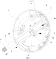
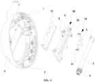
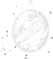
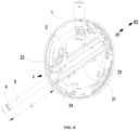
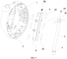
- FIG. 1 , FIG. 2 , FIG. 3 , FIG. 4 , FIG. 5 , FIG. 6 , FIG. 7 , FIG. 8 , FIG. 9 and FIG. 10 will be described below with reference to FIG. 1 , FIG. 2 , FIG. 3 , FIG. 4 , FIG. 5 , FIG. 6 , FIG. 7 , FIG. 8 , FIG. 9 and FIG. 10 .
- An embodiment provides an earpiece, including a housing 1, a microphone boom 3, a microphone 4 and a force application structure FA for applying a predetermined force F to the microphone boom 3.
- a cavity 2 is formed in the housing 1.
- a guiding structure GU for guiding the microphone boom 3 to slide and switch between a first position and a second position is provided on the housing 1.
- the microphone boom 3 slides along a first direction D1, and an included angle formed between a direction of the predetermined force F and the first direction D1 is switched from a first predetermined angle of greater than 90° to a second predetermined angle of less than 90°.
- the microphone boom 3 slides along a second direction D2
- an included angle formed between the direction of the predetermined force F and the second direction D2 is switched from a third predetermined angle of greater than 90° to a fourth predetermined angle of less than 90°.
- the microphone boom 3 may be provided at an outer side of the housing 1, which facilitates the subsequent maintenance on the directly exposed microphone boom 3, and further facilitates the manual operation of the user on the directly exposed microphone boom 3 to slide the microphone boom 3 from the first position to the second position or from the second position to the first position.
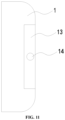
- a base 13 is provided at the outer side of the housing 1.
- An accommodating space is formed in the base 13.
- An opening 14 communicating with the accommodating space is formed in the base 13.
- the microphone boom 3 passes through the opening, with a part extending to the accommodating space.
- the microphone 4 is provided on the microphone boom 3 extending out of the accommodating space.
- the base 13 may be embedded into the outer side of the housing 1, as shown in FIG. 11 .
- the base 13 may also be directly provided at the outer side of the housing 1, as shown in FIG. 12 .
- the guiding structure GU may be provided at the outer side of the housing 1 together with the microphone boom 3, and may also be provided in the housing 1 and connected to the microphone boom 3 at the outer side of the housing 1.
- the microphone boom 3 is provided in the housing 1.
- the earpiece further includes a lid.
- the lid covers the cavity 2.
- the guiding structure GU is provided in the cavity 2.
- the via hole 9 for allowing the microphone boom 3 to pass through is formed in the housing 1.
- a part of the microphone boom 3 passes through the via hole 9 and extends out of the cavity 2.
- the microphone 4 is provided on the microphone boom 3 extending out of the cavity 2. Compared with the manner that the microphone boom 3 is provided at the outer side of the housing 1, the preferable implementation can better protect the microphone boom 3.
- the lid follows the shape of a cochlea, so the earpiece is sleeved by the user to the cochlea conveniently.
- the lid covers the cochlea of the user.
- the microphone boom 3 is located at the first position, and the microphone 4 is retracted to a position close to the via hole 9.
- the microphone boom 3 extending out of the cavity 2 is manually operated by the user, and under the guidance of the guiding structure GU, the microphone boom 3 slides to the second position along the first direction D1.
- the predetermined force F applied by the force application structure FA prevents the microphone boom 3 from sliding, and thus a greater force will be applied by the user to overcome the obstruction of the predetermined force F.
- the predetermined force F applied by the force application structure FA does not prevent the microphone boom 3 from sliding.
- the predetermined force F applied by the force application structure FA facilitates the sliding movement of the microphone boom 3 and pushes the microphone boom 3 to slide. In this case, the microphone boom 3 slides to the second position without the manual operation of the user.
- the microphone boom 3 When the microphone 4 is not used, and the microphone boom 3 needs to slide from the second position to the first position along the second direction D2, the above process is reversed.
- the angle between the direction of the predetermined force F and the second direction D2 is switched from the third predetermined angle to the fourth predetermined angle, the predetermined force F first prevents the microphone boom 3 from sliding and then facilitates the sliding movement of the microphone boom 3.
- the included angle formed between the predetermined force F and the second direction D2 is less than 90°, the microphone boom 3 can slide to the first position without the manual operation of the user.
- the microphone boom 3 When the microphone boom 3 is located at the first position, the microphone boom 3 tends to slide along the first direction D1 in case of an unexpected external force applied to the microphone boom 3. Nevertheless, as the first predetermined angle of greater than 90° is formed between the predetermined force F and the first direction D1, the microphone boom 3 is stably fixed at the first position without shaking under the influence of the predetermined force F.
- the microphone boom 3 when the microphone boom 3 is located at the second position, the microphone boom 3 tends to slide along the second direction D2 in case of an unexpected external force applied to the microphone boom 3. Nevertheless, as the third predetermined angle of greater than 90° is formed between the predetermined force F and the second direction D2, the microphone boom 3 is stably fixed at the second position without shaking under the influence of the predetermined force F.
- the microphone boom can be stretched out or retracted according to a preset route regardless of whether a track is provided, minimizing the space for stretching out or retracting the microphone.
- the microphone boom 3 is located at the first position, namely the microphone 4 is in a retracted state
- the first direction D1 refers to a direction from which the microphone boom 3 is manually pulled out
- the first predetermined angle of greater than 90° is formed between the direction of the predetermined force F and the first direction D1
- the predetermined force F obstructs the sliding tendency of the microphone boom 3 and prevents the microphone boom 3 from sliding.
- the predetermined force F faces toward the cavity, such that the microphone boom 3 abuts against the cavity 2, and the microphone boom 3 can be stably kept at the first position under balanced force.
- the included angle formed between the direction of the predetermined force F and the first direction D1 is switched from the first predetermined angle to the second predetermined angle of less than 90°, the predetermined force F follows the sliding tendency of the microphone boom 3 and pushes the microphone boom 3 to slide toward the second position, and thus with the predetermined force F, the microphone boom can slide semi-automatically.
- the microphone boom 3 When the microphone 4 is not used, the microphone boom 3 is located at the second position, namely the microphone 4 is in a stretched state, the second direction D2 refers to a direction into which the microphone boom 3 is manually pushed, the first predetermined angle of greater than 90° is formed between the direction of the predetermined force F and the second direction D2, the predetermined force F obstructs the sliding tendency of the microphone boom 3 and prevents the microphone boom 3 from sliding, and the force on microphone boom 3 is balanced and it is stably kept at the second position under the predetermined force F.
- the included angle formed between the direction of the predetermined force F and the second direction D2 is switched from the first predetermined angle to the second predetermined angle of less than 90°, the predetermined force F follows the sliding trenchancy of the microphone boom 3 and pushes the microphone boom 3 to slide toward the second position, and with the predetermined force F, the microphone boom slides semi-automatically.
- the microphone boom 3 has the advantages of hard shaking and stable structure, and the microphone boom 3 is stretched out or retracted without manual operation. The user only needs to pull out or push into a part of the microphone boom 3, and a remaining part of the microphone boom is automatically moved by the force application structure FA, so the earpiece is operated simply and conveniently, with the good user experience.
- the guiding structure GU is a sliding track 6 matched with the microphone boom 3.
- the earpiece further includes a first switch 7 electrically connected to the microphone boom 3 and configured to turn the microphone 4 on or off.
- the first switch 7 When the microphone boom 3 is located at the first position, the first switch 7 is in a first state, the microphone 4 is turned off and the microphone 4 is muted.
- the first switch 7 When the microphone boom 3 is located at the second position, the first switch 7 is in a second state, and the microphone 4 is turned on.
- the guiding structure GU is designed as the sliding track 6 matched with the microphone boom 3, the first switch 7 is provided in the sliding track 6.
- the first switch 7 is a contact switch.
- the microphone boom 3 When the microphone boom 3 is located at the first position, the microphone boom 3 contacts the first switch 7 and the first switch 7 is open, to mute the microphone 4.
- the first switch 7 When the guiding structure GU is designed as the sliding track 6 matched with the microphone boom 3, the first switch 7 is provided at a position away from the via hole 9 in the sliding track 6, so as to contact and open the first switch 7 when the microphone boom 3 is located at the first position.
- the microphone boom 3 is of a linear rod structure.
- the microphone boom 3 is of a curved rod structure.
- the microphone boom 3 is of a telescopic rod structure.
- the first predetermined angle and the fourth predetermined angle are complementary to one another, and the second predetermined angle and the third predetermined angle are complementary to one another.
- a seat is further provided in the cavity 2.
- the microphone boom 3 is connected to the seat and is stretched out or retracted under the action of the guiding structure GU.
- the microphone boom 3 may be of a multi-section telescopic structure.
- a speaker is further provided in the cavity 2 to implement a sound play function. In cooperation with the microphone 4, the sound can be received and played.
- the speaker is provided with a sound producing hole on a surface of the lid.
- a limiting member 25 for limiting the microphone boom 3 to slide is provided on an inner wall of the cavity 2.
- the limiting member 25 is located in the first direction D1 of the microphone boom 3 and abuts against the microphone boom 3, thereby limiting the microphone boom 3 to continuously slide along the first direction D1 and preventing the microphone boom 3 from sliding out of the cavity 2.
- the microphone boom 3 may further include a sliding member slidably provided on the sliding track 6.
- the limiting member 25 abuts against the sliding member, which limits the microphone boom 3 to continuously slide along the first direction D1 and prevents the microphone boom 3 from sliding out of the cavity 2.
- both the cavity 2 and the microphone 4 have a centroid, with a midline 11 defined as follows: When the microphone boom 3 is located at the second position, a straight line passing through the centroid of the microphone 4 and the centroid of the cavity 2 is the midline 11.
- the included angle formed between the midline 11 and the Frankfurt plane 12 is the predetermined included angle in use.
- the Frankfurt plane 12 refers to a plane formed by points on upper margins of external auditory canals at two sides of the skull and a point on a lower margin of the left orbit.
- the Frankfurt plane 12 passes through the centroid of the cavity 2 in use.
- the predetermined included angle is any value in a range of 35° ⁇ 15°.
- ⁇ A sin ⁇ 1 a a 2 + b 2
- a is a perpendicular distance between a horizontal plane of the human earhole and a horizontal plane of the human mouth
- b is a perpendicular distance between a vertical plane of the earhole and a vertical plane of the mouth.
- the earpiece further includes a second switch for turning on or off the microphone 4.
- the second switch is provided on the microphone boom 3 extending out of the cavity 2or provided on the housing 1.
- the second switch is provided in the embodiment.
- the present disclosure provides the following embodiments for the force application structure FA:
- the embodiment provides a structure for the force application structure FA in the present disclosure.
- the force application structure FA includes an elastic member 5.
- the elastic member 5 is provided with a first end 51 connected to an inner wall of the cavity 2 and a second end 52 connected to the microphone boom 3 in the cavity 2.
- the predetermined force F is an elastic force applied by the second end 52 to the microphone boom 3.
- the first direction D1 refers to the direction from which the microphone boom 3 is manually pulled out
- an obtuse angle of greater than 90° is formed between the direction of the predetermined force F applied by the elastic member 5 to the microphone boom 3 and the first direction D1, and the predetermined force F prevents the microphone boom 3 from sliding.
- the elastic member 5 When the microphone boom 3 slides continuously to a position at a minimal distance between the first end 51 and the second end 52, the elastic member 5 is compressed maximally, namely the predetermined force F reaches a maximum. However, as the direction of the predetermined force F is perpendicular to the first direction D1, the predetermined force F does not prevent the microphone boom 3 from sliding.
- the elastic member 5 While the microphone boom 3 slides continuously, the distance between the first end 51 and the second end 52 is increased, and the elastic member 5 is restored. In this case, an acute angle of less than 90° is formed between the direction of the predetermined force F applied by the elastic member 5 to the microphone boom 3 and the first direction D1, the elastic member 5 facilitates the sliding movement of the microphone boom 3, and the microphone boom is automatically stretched out without manual operation of the user.
- the second direction D2 refers to the direction into which the microphone boom is manually pushed, an obtuse angle of greater than 90° is formed between the direction of the predetermined force F applied by the elastic member 5 to the microphone boom 3 and the second direction D2, and the predetermined force F prevents the microphone boom 3 from sliding.
- the elastic member 5 When the microphone boom 3 slides continuously to a position at a minimal distance between the first end 51 and the second end 52, the elastic member 5 is compressed maximally, namely the predetermined force F reaches a maximum. However, as the direction of the predetermined force F is perpendicular to the second direction D2, the predetermined force F does not prevent the microphone boom 3 from sliding.
- the elastic member 5 facilitates the sliding movement of the microphone boom 3, and the microphone boom is automatically retracted without manual operation of the user.
- the force on the microphone boom 3 is balanced and it is kept at the first position through the elastic force.
- the force on the microphone boom 3 is balanced and it is kept at the second position through the elastic force.
- the spring in the embodiment has the simple structure and low cost, without affecting a magnetic coil in the speaker and the microphone 4.
- the embodiment stretches out or retracts the microphone 4 slidably, with the small space and no winding structure.
- the sliding track 6 is defined by a sliding frame 8 with grooves.
- the grooves in the sliding frame 8 enclose the sliding track 6.
- a plurality of flanges are arranged on the sliding frame 8.
- First through holes are formed in the plurality of flanges.
- a plurality of second through holes in one-to-one correspondence with a plurality of the first through holes are formed in the inner wall of the cavity 2.
- the sliding frame 8 is provided on the inner wall of the cavity 2 through a plurality of threaded rods in one-to-one correspondence with the first through holes.
- a mounting seat 10 is provided on a bottom wall of the cavity 2.
- the second through holes are formed in the mounting seat 10.
- Clamping grooves for accommodating the sliding frame 8 are formed in the mounting seat 10.
- the elastic member 5 is compressed to fix the microphone boom 3 at the first position and the second position.
- the earpiece further includes a first bolt.
- An end of the microphone boom 3 in the cavity 2 is provided with a first threaded hole.
- the first bolt is in threaded connection with the first threaded hole and fixes the second end 52 on the microphone boom 3.
- the fixing effect is better by winding the second end 52 on the second bolt.
- the earpiece further includes a second bolt.
- a second threaded hole is formed in the inner wall of the cavity 2.
- the second bolt is in threaded connection with the second threaded hole and fixes the first end 51 on the inner wall of the cavity 2.
- the fixing effect is better by winding the first end 51 on the second bolt.
- the cavity 2 is provided with a bottom wall and a sidewall.
- the first end 51 is connected to the bottom wall of the cavity 2.
- the force application structure FA includes a first magnet 21 in the cavity 2 and a second magnet 22 on the microphone boom 3 in the cavity 2.
- the first magnet 21 and the second magnet 22 are the same in magnetism.
- the predetermined force F is a repulsive force between the first magnet 21 and the second magnet 22.
- first magnet 21 and the second magnet 22 have the magnetism does not mean that the first magnet 21 and the second magnet 22 each include a magnetic substance, but the first magnet 21 serves as one magnetic pole of a magnetic substance having positive or negative magnetic poles, and the second magnet 22 also serves as one magnetic pole of a magnetic substance having positive or negative magnetic poles.
- the first direction D1 refers to the direction from which the microphone boom is manually pulled out
- an obtuse angle of greater than 90° is formed between the predetermined force F applied by the first magnet 21 to the second magnet 22 and the first direction D1, and the predetermined force F prevents the microphone boom 3 from sliding.
- the repulsive force reaches a maximum, namely the predetermined force F reaches a maximum.
- the predetermined force F does not prevent the microphone boom 3 from sliding.
- the microphone boom 3 slides continuously, the distance between the first end 21 and the second end 22 is increased, and there is still mutual repulsion between the first magnet 21 and the second magnet 22.
- an acute angle of less than 90° is formed between the direction of the predetermined force F applied by the first magnet 21 to the microphone boom 3 and the first direction D1, the first magnet 21 facilitates the sliding movement of the microphone boom 3, and the microphone boom is automatically stretched out without manual operation of the user.
- the second direction D2 refers to the direction into which the microphone boom is manually pushed, an obtuse angle of greater than 90° is formed between the predetermined force F applied by the first magnet 21 to the second magnet 22 and the sliding direction of the microphone boom 3, and the predetermined force F prevents the microphone boom 3 from sliding.
- the repulsive force reaches a maximum, namely the predetermined force F reaches a maximum.
- the predetermined force F does not prevent the microphone boom 3 from sliding.
- the force on the microphone boom 3 is balanced and it is kept at the first position through the repulsive force.
- the force on the microphone boom 3 is balanced and it is kept at the second position through the repulsive force.
- the embodiment Compared with other embodiments of the force application structure FA, with the magnets, the embodiment has the stable force application, long service life, and low cost.
- the embodiment stretches out or retracts the microphone 4 slidably, with the small space and no winding structure.
- the sliding track 6 is defined by a sliding frame 8 with grooves.
- the grooves in the sliding frame 8 enclose the sliding track 6.
- a plurality of flanges are arranged on the sliding frame 8.
- First through holes are formed in the plurality of flanges.
- a plurality of second through holes in one-to-one correspondence with a plurality of the first through holes are formed in the inner wall of the cavity 2.
- the sliding frame 8 is provided on the inner wall of the cavity 2 through a plurality of threaded rods in one-to-one correspondence with the first through holes.
- a mounting seat 10 is provided on a bottom wall of the cavity 2.
- the second through holes are formed in the mounting seat 10.
- Clamping grooves for accommodating the sliding frame 8 are formed in the mounting seat 10.
- first magnets 21 that are arranged at two sides of the sliding track 6.
- the second magnet 22 is provided at an end of the microphone boom 3 away from the via hole 9.
- the earpiece further includes a first fixing member 23 provided in the cavity 2 and configured to fix the microphone boom 3 at the first position.
- the first fixing member 23 is an integrated member made of a magnetic material. When the microphone boom 3 is located at the first position, the first fixing member 23 generates a first attractive force to the second magnet 22 to fix the microphone boom 3 at the first position.
- the microphone boom 3 there is a certain distance between the first magnet 21 and the second magnet 22, particularly for the case where the second magnet 22 is provided at the end of the microphone boom 3 away from the via hole 9.
- the first fixing member 23 is increased in the embodiment. With the mutual attractive force between the first fixing member 23 and the second magnet 22, the microphone boom 3 is fixed at the first position.
- the first fixing member 23 may be provided on an extending line of the sliding track 6, such that the microphone boom 3 is directly fixed with the mutual attractive force between the first fixing member 23 and the second magnet 22.
- the first fixing member 23 may also be provided on a perpendicular line perpendicular to the sliding track 6, such that a frictional force between the microphone boom 3 and the sliding track 6 is increased with the mutual attractive force between the first fixing member 23 and the second magnet 22, and the microphone boom 3 is indirectly fixed with the mutual attractive force between the first fixing member 23 and the second magnet 22.
- the first fixing member 23 has magnetism reverse to that of the first magnet 21.
- the first fixing member 23 may be made of a magnetizable material.
- the first fixing member 23 may be made of iron. The first iron fixing member 23 can attract the first magnet 21 after magnetized by the first magnet 21.
- first fixing members 23 that are arranged at the two sides of the sliding track 6.
- the earpiece further includes a second fixing member 24 provided in the cavity 2 and configured to fix the microphone boom 3 at the second position.
- the second fixing member 24 is an integrated member made of a magnetic material. When the microphone boom 3 is located at the second position, the first fixing member 24 generates a second attractive force to the second magnet 22 to fix the microphone boom 3 at the second position.
- the second fixing member 24 has magnetism reverse to that of the second magnet 22.
- the second fixing member 24 may be made of a magnetizable material.
- the second fixing member 24 may be made of iron. The second iron fixing member 24 can attract the second magnet 22 after magnetized by the second magnet 22.
- the second fixing member 24 may be provided on the extending line of the sliding track 6, such that the frictional force between the microphone boom 3 and the sliding track 6 is increased with the mutual attractive force between the second fixing member 24 and the first magnet 21, and the microphone boom 3 is indirectly fixed with the mutual attractive force between the second fixing member 24 and the second magnet 22.
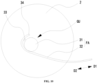
- the force application structure FA includes a stripped winding portion 32 and a motor 31 with an output shaft.
- the predetermined force F is a frictional force applied by the output shaft to the winding portion 32.
- a third switch 33 for starting or stopping the motor 31 is provided on the motor 31.
- the winding portion 32 is wound on the output shaft of the motor 31, with one end of the winding portion 32 connected to the microphone boom 3. When the output shaft of the motor 31 rotates, the winding portion 32 drives the microphone boom 3 to slide between the first position and the second position.
- An opening/closing member 34 for closing the third switch 33 is provided on the winding portion 32.
- the opening/closing member 34 starts the motor 31 through the third switch 33 and drives the microphone boom 3 to slide toward the second position.
- the third switch 33 is open.
- the opening/closing member 34 starts the motor 31 through the third switch 33 and drives the microphone boom 3 to slide toward the first position.
- the third switch 33 is open.
- the guiding structure GU is the output shaft of the motor 31, and the winding portion 32 rotates around the output shaft of the motor 31, such that the microphone boom 3 can slide and switch between the first position and the second position under the guidance of the output shaft of the motor 31.
- the force application structure FA implements the semi-automatic switching of the microphone boom 3 between the first position and the second position, there is no need to additionally provide the physical structure such as the sliding track 6 to guide the microphone boom 3.
- the winding portion 32 is taken as a part of the microphone boom 3, the first direction D1 and the second direction D2 are respectively tangential directions on a rotation trajectory for a part of the winding portion 32 wound on the output shaft of the motor 31, and the included angle formed between the direction of the predetermined force F and the first direction D1 or the second direction D2 is 180° or 0° constantly.
- An included angle of 180° is formed between the predetermined force F, which is the direction of the frictional force applied by the output shaft of the motor 31 to the winding portion 32, and the first direction D1, so the predetermined force F prevents the microphone boom 3 from sliding.
- the opening/closing member 34 contacts the third switch 33.
- the third switch 33 sends a signal to drive rotation of the output shaft of the motor 31. With the rotation of the output shaft, relative velocities of the output shaft and the winding portions are gradually decreased, and the predetermined force F is gradually decreased to 0. In this case, the force application structure FA does not prevent the microphone boom 3 from sliding.
- the predetermined force F is increased again from 0.
- an included angle of 0° is formed between the direction of the predetermined force F and the first direction D1
- the predetermined force F facilitates the sliding movement of the microphone boom 3, and the microphone boom 3 is automatically stretched out without manual operation of the user.
- the microphone boom 3 can also be stably fixed at the second position.
- An included angle of 180° is formed between the predetermined force F, which is the direction of the frictional force applied by the output shaft of the motor 31 to the winding portion 32, and the second direction D2, so the predetermined force F prevents the microphone boom 3 from sliding.
- the opening/closing member 34 contacts the third switch 33 again.
- the third switch 33 sends a signal to drive rotation of the output shaft of the motor 31.
- the predetermined force F is gradually decreased to 0. In this case, the force application structure FA does not prevent the microphone boom 3 from sliding.
- the predetermined force F is increased again from 0.
- an included angle of 0° is formed between the direction of the predetermined force F and the second direction D2
- the predetermined force F facilitates the sliding movement of the microphone boom 3, and the microphone boom 3 is automatically retracted without manual operation of the user.
- the force on the microphone boom 3 is balanced and it is kept at the first position through the elastic force.
- the force on the microphone boom 3 is balanced and it is kept at the second position through the elastic force.
- the winding portion 32 may be made of a hard material, such that the microphone boom can be stably stretched out or retracted along the preset route, and the microphone boom is not shaken easily at the first position or the second position.
- the motor 31 in the embodiment has the stable force application and long service life, without affecting a magnetic coil in the speaker and the microphone 4.
Landscapes
- Engineering & Computer Science (AREA)
- Physics & Mathematics (AREA)
- Acoustics & Sound (AREA)
- Signal Processing (AREA)
- Manufacturing & Machinery (AREA)
- Details Of Audible-Bandwidth Transducers (AREA)
- Telephone Set Structure (AREA)
Claims (8)
- Ein Ohrhörer, umfassend ein Gehäuse (1), einen Mikrofonarm (3), ein Mikrofon (4) und eine Kraftanwendungseinrichtung (FA) zur Ausübung einer vorbestimmten Kraft (F) auf den Mikrofonarm (3), wobeieine Führungseinrichtung (GU) zur Führung des Mikrofonarms (3) zum Gleiten und Wechseln zwischen einer ersten Position und einer zweiten Position am Gehäuse (1) vorgesehen ist;wenn sich der Mikrofonarm (3) in der ersten Position befindet, erreicht ein Abstand (L) zwischen dem Mikrofon (4) und einem Durchgangsloch (9) ein erstes Limit, und der Mikrofonarm (3) steht unter ausgeglichener Kraft; und wenn sich der Mikrofonarm (3) in der zweiten Position befindet, erreicht der Abstand (L) zwischen dem Mikrofon (4) und dem Durchgangsloch (9) ein zweites Limit, das größer ist als das erste Limit, und der Mikrofonarm (3) steht unter ausgeglichener Kraft;wobei der Ohrhörer ferner einen ersten Schalter (7) umfasst, der elektrisch mit dem Mikrofonarm (3) verbunden ist und dazu konfiguriert ist, das Mikrofon (4) ein- oder auszuschalten, wobei wenn sich der Mikrofonarm (3) in der ersten Position befindet, der erste Schalter (7) in einem ersten Zustand ist, und das Mikrofon (4) ausgeschaltet ist; und wenn sich der Mikrofonarm (3) in der zweiten Position befindet, der erste Schalter (7) in einem zweiten Zustand ist, und das Mikrofon (4) eingeschaltet ist;wobei, wenn der Mikrofonarm (3) von der ersten Position in die zweite Position gleitet, der Mikrofonarm (3) entlang einer ersten Richtung (D1) gleitet, und ein eingeschlossener Winkel, der zwischen einer Richtung der vorbestimmten Kraft (F) und der ersten Richtung (D1) gebildet wird, von einem ersten vorbestimmten Winkel größer als 90° auf einen zweiten vorbestimmten Winkel kleiner als 90° umgeschaltet wird;und wenn der Mikrofonarm (3) von der zweiten Position in die erste Position gleitet, der Mikrofonarm (3) entlang einer zweiten Richtung (D2) gleitet, und ein eingeschlossener Winkel, der zwischen der Richtung der vorbestimmten Kraft (F) und der zweiten Richtung (D2) gebildet wird, von einem dritten vorbestimmten Winkel größer als 90° auf einen vierten vorbestimmten Winkel kleiner als 90° umgeschaltet wird;wobei der Ohrhörer ferner einen Deckel umfasst; eine Höhlung (2) wird im Gehäuse (1) gebildet, und der Deckel bedeckt die Höhlung (2);die Führungseinrichtung (GU) ist in der Höhlung (2) vorgesehen; unddas Durchgangsloch (9), das es dem Mikrofonarm (3) ermöglicht, hindurchzugehen, wird im Gehäuse (1) gebildet; ein Teil des Mikrofonarms (3) geht durch das Durchgangsloch (9) und erstreckt sich aus der Höhlung (2); und das Mikrofon (4) ist an dem Mikrofonarm (3) angebracht, der sich aus der Höhlung (2) erstreckt;die Kraftanwendungseinrichtung (FA) umfasst ein elastisches Element (5);dadurch gekennzeichnet, dass das elastische Element (5) mit einem ersten Ende (51) verbunden ist, das an einer Innenwand der Höhlung (2) befestigt ist, und einem zweiten Ende (52), das in der Höhlung (2) mit dem Mikrofonarm (3) verbunden ist;wenn der Mikrofonarm (3) von der ersten Position in die zweite Position gleitet, wird zunächst der Abstand zwischen dem ersten Ende (51) und dem zweiten Ende (52) verringert, das elastische Element (5) wird zusammengedrückt, ein stumpfer Winkel größer als 90° wird zwischen der Richtung der vorbestimmten Kraft (F), die vom elastischen Element (5) auf den Mikrofonarm (3) ausgeübt wird, und einer ersten Richtung (D1), aus der der Mikrofonarm (3) manuell herausgezogen wird, gebildet;dann gleitet der Mikrofonarm (3) weiter in eine Position mit minimalem Abstand zwischen dem ersten Ende (51) und dem zweiten Ende (52), das elastische Element (5) wird maximal zusammengedrückt, die vorbestimmte Kraft (F) erreicht ein Maximum, und die Richtung der vorbestimmten Kraft (F) ist senkrecht zur ersten Richtung (D1);dann, während der Mikrofonarm (3) weiter gleitet, wird der Abstand zwischen dem ersten Ende (51) und dem zweiten Ende (52) vergrößert, das elastische Element (5) wird wiederhergestellt, ein spitzer Winkel kleiner als 90° wird zwischen der Richtung der vorbestimmten Kraft (F) und der ersten Richtung (D1) gebildet, der Mikrofonarm (3) wird automatisch herausgestreckt;der Ohrhörer umfasst ferner einen zweiten Schalter, der dazu konfiguriert ist, das Mikrofon (4) ein- oder auszuschalten, der zweite Schalter ist an dem Mikrofonarm (3) angebracht, der sich aus der Höhlung (2) erstreckt, oder ist am Gehäuse (1) angebracht.
- Der Ohrhörer gemäß Anspruch 1, wobei die Führungseinrichtung (GU) eine Gleitbahn (6) ist, die auf den Mikrofonarm (3) abgestimmt ist.
- Der Ohrhörer gemäß Anspruch 2, wobei der erste Schalter (7) ein Kontaktschalter ist.
- Der Ohrhörer gemäß Anspruch 1, wobei der Mikrofonarm (3) eine lineare stabähnliche Struktur oder eine bogenförmige stabähnliche Struktur aufweist.
- Der Ohrhörer gemäß Anspruch 1, wobei ein Begrenzungselement (25) an einer Innenwand der Höhlung (2) vorgesehen ist; und
wenn sich der Mikrofonarm (3) in der zweiten Position befindet, befindet sich das Begrenzungselement (25) in der ersten Richtung (D1) des Mikrofonarms (3) und stößt gegen den Mikrofonarm (3). - Der Ohrhörer gemäß Anspruch 1, wobei die Kraftanwendungseinrichtung (FA) einen ersten Magneten (21) in der Höhlung (2) und einen zweiten Magneten (22) am Mikrofonarm (3) in der Höhlung (2) umfasst;der erste Magnet (21) und der zweite Magnet (22) haben die gleiche Magnetisierung; und die vorbestimmte Kraft (F) ist eine Abstoßungskraft zwischen dem ersten Magneten (21) und dem zweiten Magneten (22); undwenn der Mikrofonarm (3) von der ersten Position in die zweite Position gleitet, wird der Abstand zwischen dem ersten Magneten (21) und dem zweiten Magneten (22) zunächst verringert und dann vergrößert.
- Der Ohrhörer gemäß Anspruch 6, ferner umfassend ein erstes Befestigungselement (23), das in der Höhlung (2) vorgesehen ist und dazu konfiguriert ist, den Mikrofonarm (3) in der ersten Position zu fixieren, und ein zweites Befestigungselement (24), das in der Höhlung (2) vorgesehen ist und dazu konfiguriert ist, den Mikrofonarm (3) in der zweiten Position zu fixieren, wobeidas erste Befestigungselement (23) ein integriertes Element ist, das aus einem magnetischen Material besteht; das erste Befestigungselement (23) hat eine entgegengesetzte Magnetisierung zum zweiten Magneten (22); das zweite Befestigungselement (24) ist ein integriertes Element, das aus einem magnetischen Material besteht; und das zweite Befestigungselement (24) hat eine entgegengesetzte Magnetisierung zum zweiten Magneten (22);wenn sich der Mikrofonarm (3) in der ersten Position befindet,erzeugt das erste Befestigungselement (23) eine erste Anziehungskraft auf den zweiten Magneten (22), um den Mikrofonarm (3) in der ersten Position zu fixieren; undwenn sich der Mikrofonarm (3) in der zweiten Position befindet,erzeugt das zweite Befestigungselement (24) eine zweite Anziehungskraft auf den zweiten Magneten (22), um den Mikrofonarm (3) in der zweiten Position zu fixieren.
- Der Ohrhörer gemäß Anspruch 1, wobei der Mikrofonarm (3) an der Außenseite des Gehäuses (1) vorgesehen ist.
Applications Claiming Priority (3)
| Application Number | Priority Date | Filing Date | Title |
|---|---|---|---|
| CN202110391913.0A CN113079436A (zh) | 2021-04-12 | 2021-04-12 | 一种耳麦 |
| CN202120740988.0U CN215187298U (zh) | 2021-04-12 | 2021-04-12 | 一种耳麦 |
| CN202220769999.6U CN217063975U (zh) | 2022-04-02 | 2022-04-02 | 一种耳麦 |
Publications (2)
| Publication Number | Publication Date |
|---|---|
| EP4075823A1 EP4075823A1 (de) | 2022-10-19 |
| EP4075823B1 true EP4075823B1 (de) | 2024-11-27 |
Family
ID=81307261
Family Applications (1)
| Application Number | Title | Priority Date | Filing Date |
|---|---|---|---|
| EP22167823.8A Active EP4075823B1 (de) | 2021-04-12 | 2022-04-12 | Ohrhörer |
Country Status (2)
| Country | Link |
|---|---|
| US (1) | US11917357B2 (de) |
| EP (1) | EP4075823B1 (de) |
Families Citing this family (1)
| Publication number | Priority date | Publication date | Assignee | Title |
|---|---|---|---|---|
| US12382206B2 (en) * | 2022-09-07 | 2025-08-05 | Sony Interactive Entertainment LLC | Headset with reciprocating microphone support |
Citations (3)
| Publication number | Priority date | Publication date | Assignee | Title |
|---|---|---|---|---|
| CN103763654A (zh) * | 2014-01-20 | 2014-04-30 | 东莞市晶丰电子科技有限公司 | 咪杆伸缩耳机 |
| CN107635174A (zh) * | 2017-11-13 | 2018-01-26 | 上海贤广信息科技有限公司 | 一种可自动伸缩、自动升降的蓝牙耳机 |
| CN211128135U (zh) * | 2020-02-17 | 2020-07-28 | 上海贤广信息科技有限公司 | 一种新型结构蓝牙耳机 |
Family Cites Families (11)
| Publication number | Priority date | Publication date | Assignee | Title |
|---|---|---|---|---|
| US5999822A (en) * | 1997-03-14 | 1999-12-07 | Sony Corporation | Cellular telephone with extendible microphone |
| US7349547B1 (en) * | 2001-11-20 | 2008-03-25 | Plantronics, Inc. | Noise masking communications apparatus |
| JP4015934B2 (ja) * | 2002-04-18 | 2007-11-28 | 株式会社東芝 | 動画像符号化方法及び装置 |
| US7089042B2 (en) * | 2004-01-08 | 2006-08-08 | Fellowes, Inc. | Headset with variable gain based on position of microphone boom |
| SG126012A1 (en) * | 2005-04-02 | 2006-10-30 | Simlab Inv & Consultancy Priva | A headset with a woundable microphone boom |
| US8135157B2 (en) * | 2005-06-03 | 2012-03-13 | Nokia Corporation | Headset with adjustable boom |
| US7647081B2 (en) * | 2006-05-16 | 2010-01-12 | Nokia Corporation | Electronic device sliding mechanism |
| US20080044002A1 (en) * | 2006-07-19 | 2008-02-21 | Bevirt Joeben | Wireless headset with extendable microphone |
| US20090080683A1 (en) * | 2007-03-14 | 2009-03-26 | Bevirt Joeben | Wireless headset with microphone boom with new bending properties |
| US20130121524A1 (en) * | 2011-11-10 | 2013-05-16 | Cheng Uei Presision Industry Co., Ltd. | Headset structure |
| DK2744221T3 (en) * | 2012-12-12 | 2016-05-17 | Sennheiser Comm As | microphone Tang |
-
2022
- 2022-04-12 US US17/719,328 patent/US11917357B2/en active Active
- 2022-04-12 EP EP22167823.8A patent/EP4075823B1/de active Active
Patent Citations (3)
| Publication number | Priority date | Publication date | Assignee | Title |
|---|---|---|---|---|
| CN103763654A (zh) * | 2014-01-20 | 2014-04-30 | 东莞市晶丰电子科技有限公司 | 咪杆伸缩耳机 |
| CN107635174A (zh) * | 2017-11-13 | 2018-01-26 | 上海贤广信息科技有限公司 | 一种可自动伸缩、自动升降的蓝牙耳机 |
| CN211128135U (zh) * | 2020-02-17 | 2020-07-28 | 上海贤广信息科技有限公司 | 一种新型结构蓝牙耳机 |
Also Published As
| Publication number | Publication date |
|---|---|
| EP4075823A1 (de) | 2022-10-19 |
| US20220329929A1 (en) | 2022-10-13 |
| US11917357B2 (en) | 2024-02-27 |
Similar Documents
| Publication | Publication Date | Title |
|---|---|---|
| CN109413535B (zh) | 一种真无线立体声耳机 | |
| EP2355552B1 (de) | Hörgerät und Handhabungswerkzeug | |
| EP4075823A1 (de) | Ohrhörer | |
| EP1542345A3 (de) | Kleinst-Aktuator mit Direktantrieb | |
| US7983431B2 (en) | Bone conduction device and tympanum thereof | |
| CN215187298U (zh) | 一种耳麦 | |
| CN110958532A (zh) | 一种无线耳机充电盒及无线耳机装置 | |
| CN206451560U (zh) | 电磁体装置 | |
| EP1585363A3 (de) | Verbesserte Audiofrequenz-Lautsprecher | |
| CN113079436A (zh) | 一种耳麦 | |
| CN113810818B (zh) | 耳机组件 | |
| CN217063975U (zh) | 一种耳麦 | |
| CN114302277B (zh) | 耳机仓和耳机组件 | |
| CN210579164U (zh) | 一种无线耳机充电盒及无线耳机装置 | |
| CN216162831U (zh) | 音箱和耳机音箱组合装置 | |
| EP1427248A3 (de) | Lautsprecher | |
| CN214045714U (zh) | 一种磁吸无线充桌面支架 | |
| CN212627646U (zh) | 一种电源适配器 | |
| CN222339546U (zh) | 一种麦克风旋转收纳结构及音箱 | |
| CN223437149U (zh) | 一种可穿戴的耳机盒 | |
| CN209345326U (zh) | 一种轻量且便于携带的耳机 | |
| CN221354379U (zh) | 一种具有线缆限位功能的视频解码器 | |
| CN218750004U (zh) | 一种具有导电胶垫转动机构的线装式装订机 | |
| CN223285640U (zh) | 一种磁共振无线供电装置 | |
| CN223231268U (zh) | 一种智能麦克风收纳组件及智能设备 |
Legal Events
| Date | Code | Title | Description |
|---|---|---|---|
| PUAI | Public reference made under article 153(3) epc to a published international application that has entered the european phase |
Free format text: ORIGINAL CODE: 0009012 |
|
| STAA | Information on the status of an ep patent application or granted ep patent |
Free format text: STATUS: REQUEST FOR EXAMINATION WAS MADE |
|
| 17P | Request for examination filed |
Effective date: 20220413 |
|
| AK | Designated contracting states |
Kind code of ref document: A1 Designated state(s): AL AT BE BG CH CY CZ DE DK EE ES FI FR GB GR HR HU IE IS IT LI LT LU LV MC MK MT NL NO PL PT RO RS SE SI SK SM TR |
|
| STAA | Information on the status of an ep patent application or granted ep patent |
Free format text: STATUS: EXAMINATION IS IN PROGRESS |
|
| 17Q | First examination report despatched |
Effective date: 20230627 |
|
| GRAP | Despatch of communication of intention to grant a patent |
Free format text: ORIGINAL CODE: EPIDOSNIGR1 |
|
| STAA | Information on the status of an ep patent application or granted ep patent |
Free format text: STATUS: GRANT OF PATENT IS INTENDED |
|
| INTG | Intention to grant announced |
Effective date: 20240620 |
|
| GRAS | Grant fee paid |
Free format text: ORIGINAL CODE: EPIDOSNIGR3 |
|
| GRAA | (expected) grant |
Free format text: ORIGINAL CODE: 0009210 |
|
| STAA | Information on the status of an ep patent application or granted ep patent |
Free format text: STATUS: THE PATENT HAS BEEN GRANTED |
|
| AK | Designated contracting states |
Kind code of ref document: B1 Designated state(s): AL AT BE BG CH CY CZ DE DK EE ES FI FR GB GR HR HU IE IS IT LI LT LU LV MC MK MT NL NO PL PT RO RS SE SI SK SM TR |
|
| P01 | Opt-out of the competence of the unified patent court (upc) registered |
Free format text: CASE NUMBER: APP_57149/2024 Effective date: 20241018 |
|
| REG | Reference to a national code |
Ref country code: GB Ref legal event code: FG4D |
|
| REG | Reference to a national code |
Ref country code: CH Ref legal event code: EP |
|
| REG | Reference to a national code |
Ref country code: IE Ref legal event code: FG4D |
|
| REG | Reference to a national code |
Ref country code: DE Ref legal event code: R096 Ref document number: 602022008063 Country of ref document: DE |
|
| REG | Reference to a national code |
Ref country code: LT Ref legal event code: MG9D |
|
| REG | Reference to a national code |
Ref country code: NL Ref legal event code: MP Effective date: 20241127 |
|
| PG25 | Lapsed in a contracting state [announced via postgrant information from national office to epo] |
Ref country code: HR Free format text: LAPSE BECAUSE OF FAILURE TO SUBMIT A TRANSLATION OF THE DESCRIPTION OR TO PAY THE FEE WITHIN THE PRESCRIBED TIME-LIMIT Effective date: 20241127 Ref country code: IS Free format text: LAPSE BECAUSE OF FAILURE TO SUBMIT A TRANSLATION OF THE DESCRIPTION OR TO PAY THE FEE WITHIN THE PRESCRIBED TIME-LIMIT Effective date: 20250327 Ref country code: PT Free format text: LAPSE BECAUSE OF FAILURE TO SUBMIT A TRANSLATION OF THE DESCRIPTION OR TO PAY THE FEE WITHIN THE PRESCRIBED TIME-LIMIT Effective date: 20250327 |
|
| PG25 | Lapsed in a contracting state [announced via postgrant information from national office to epo] |
Ref country code: FI Free format text: LAPSE BECAUSE OF FAILURE TO SUBMIT A TRANSLATION OF THE DESCRIPTION OR TO PAY THE FEE WITHIN THE PRESCRIBED TIME-LIMIT Effective date: 20241127 Ref country code: NL Free format text: LAPSE BECAUSE OF FAILURE TO SUBMIT A TRANSLATION OF THE DESCRIPTION OR TO PAY THE FEE WITHIN THE PRESCRIBED TIME-LIMIT Effective date: 20241127 |
|
| REG | Reference to a national code |
Ref country code: AT Ref legal event code: MK05 Ref document number: 1746907 Country of ref document: AT Kind code of ref document: T Effective date: 20241127 |
|
| PG25 | Lapsed in a contracting state [announced via postgrant information from national office to epo] |
Ref country code: BG Free format text: LAPSE BECAUSE OF FAILURE TO SUBMIT A TRANSLATION OF THE DESCRIPTION OR TO PAY THE FEE WITHIN THE PRESCRIBED TIME-LIMIT Effective date: 20241127 |
|
| PG25 | Lapsed in a contracting state [announced via postgrant information from national office to epo] |
Ref country code: ES Free format text: LAPSE BECAUSE OF FAILURE TO SUBMIT A TRANSLATION OF THE DESCRIPTION OR TO PAY THE FEE WITHIN THE PRESCRIBED TIME-LIMIT Effective date: 20241127 |
|
| PG25 | Lapsed in a contracting state [announced via postgrant information from national office to epo] |
Ref country code: NO Free format text: LAPSE BECAUSE OF FAILURE TO SUBMIT A TRANSLATION OF THE DESCRIPTION OR TO PAY THE FEE WITHIN THE PRESCRIBED TIME-LIMIT Effective date: 20250227 |
|
| PG25 | Lapsed in a contracting state [announced via postgrant information from national office to epo] |
Ref country code: LV Free format text: LAPSE BECAUSE OF FAILURE TO SUBMIT A TRANSLATION OF THE DESCRIPTION OR TO PAY THE FEE WITHIN THE PRESCRIBED TIME-LIMIT Effective date: 20241127 Ref country code: AT Free format text: LAPSE BECAUSE OF FAILURE TO SUBMIT A TRANSLATION OF THE DESCRIPTION OR TO PAY THE FEE WITHIN THE PRESCRIBED TIME-LIMIT Effective date: 20241127 Ref country code: GR Free format text: LAPSE BECAUSE OF FAILURE TO SUBMIT A TRANSLATION OF THE DESCRIPTION OR TO PAY THE FEE WITHIN THE PRESCRIBED TIME-LIMIT Effective date: 20250228 |
|
| PG25 | Lapsed in a contracting state [announced via postgrant information from national office to epo] |
Ref country code: PL Free format text: LAPSE BECAUSE OF FAILURE TO SUBMIT A TRANSLATION OF THE DESCRIPTION OR TO PAY THE FEE WITHIN THE PRESCRIBED TIME-LIMIT Effective date: 20241127 |
|
| PG25 | Lapsed in a contracting state [announced via postgrant information from national office to epo] |
Ref country code: RS Free format text: LAPSE BECAUSE OF FAILURE TO SUBMIT A TRANSLATION OF THE DESCRIPTION OR TO PAY THE FEE WITHIN THE PRESCRIBED TIME-LIMIT Effective date: 20250227 |
|
| PG25 | Lapsed in a contracting state [announced via postgrant information from national office to epo] |
Ref country code: SM Free format text: LAPSE BECAUSE OF FAILURE TO SUBMIT A TRANSLATION OF THE DESCRIPTION OR TO PAY THE FEE WITHIN THE PRESCRIBED TIME-LIMIT Effective date: 20241127 |
|
| PGFP | Annual fee paid to national office [announced via postgrant information from national office to epo] |
Ref country code: DE Payment date: 20250428 Year of fee payment: 4 |
|
| PG25 | Lapsed in a contracting state [announced via postgrant information from national office to epo] |
Ref country code: DK Free format text: LAPSE BECAUSE OF FAILURE TO SUBMIT A TRANSLATION OF THE DESCRIPTION OR TO PAY THE FEE WITHIN THE PRESCRIBED TIME-LIMIT Effective date: 20241127 |
|
| PG25 | Lapsed in a contracting state [announced via postgrant information from national office to epo] |
Ref country code: EE Free format text: LAPSE BECAUSE OF FAILURE TO SUBMIT A TRANSLATION OF THE DESCRIPTION OR TO PAY THE FEE WITHIN THE PRESCRIBED TIME-LIMIT Effective date: 20241127 |
|
| PG25 | Lapsed in a contracting state [announced via postgrant information from national office to epo] |
Ref country code: RO Free format text: LAPSE BECAUSE OF FAILURE TO SUBMIT A TRANSLATION OF THE DESCRIPTION OR TO PAY THE FEE WITHIN THE PRESCRIBED TIME-LIMIT Effective date: 20241127 |
|
| PG25 | Lapsed in a contracting state [announced via postgrant information from national office to epo] |
Ref country code: SK Free format text: LAPSE BECAUSE OF FAILURE TO SUBMIT A TRANSLATION OF THE DESCRIPTION OR TO PAY THE FEE WITHIN THE PRESCRIBED TIME-LIMIT Effective date: 20241127 |
|
| PG25 | Lapsed in a contracting state [announced via postgrant information from national office to epo] |
Ref country code: CZ Free format text: LAPSE BECAUSE OF FAILURE TO SUBMIT A TRANSLATION OF THE DESCRIPTION OR TO PAY THE FEE WITHIN THE PRESCRIBED TIME-LIMIT Effective date: 20241127 |
|
| PG25 | Lapsed in a contracting state [announced via postgrant information from national office to epo] |
Ref country code: IT Free format text: LAPSE BECAUSE OF FAILURE TO SUBMIT A TRANSLATION OF THE DESCRIPTION OR TO PAY THE FEE WITHIN THE PRESCRIBED TIME-LIMIT Effective date: 20241127 |
|
| REG | Reference to a national code |
Ref country code: DE Ref legal event code: R097 Ref document number: 602022008063 Country of ref document: DE |
|
| PG25 | Lapsed in a contracting state [announced via postgrant information from national office to epo] |
Ref country code: SE Free format text: LAPSE BECAUSE OF FAILURE TO SUBMIT A TRANSLATION OF THE DESCRIPTION OR TO PAY THE FEE WITHIN THE PRESCRIBED TIME-LIMIT Effective date: 20241127 |
|
| PLBE | No opposition filed within time limit |
Free format text: ORIGINAL CODE: 0009261 |
|
| STAA | Information on the status of an ep patent application or granted ep patent |
Free format text: STATUS: NO OPPOSITION FILED WITHIN TIME LIMIT |
|
| REG | Reference to a national code |
Ref country code: CH Ref legal event code: L10 Free format text: ST27 STATUS EVENT CODE: U-0-0-L10-L00 (AS PROVIDED BY THE NATIONAL OFFICE) Effective date: 20251008 |
|
| 26N | No opposition filed |
Effective date: 20250828 |
|
| REG | Reference to a national code |
Ref country code: CH Ref legal event code: H13 Free format text: ST27 STATUS EVENT CODE: U-0-0-H10-H13 (AS PROVIDED BY THE NATIONAL OFFICE) Effective date: 20251125 |
|
| PG25 | Lapsed in a contracting state [announced via postgrant information from national office to epo] |
Ref country code: LU Free format text: LAPSE BECAUSE OF NON-PAYMENT OF DUE FEES Effective date: 20250412 |
|
| PG25 | Lapsed in a contracting state [announced via postgrant information from national office to epo] |
Ref country code: MC Free format text: LAPSE BECAUSE OF FAILURE TO SUBMIT A TRANSLATION OF THE DESCRIPTION OR TO PAY THE FEE WITHIN THE PRESCRIBED TIME-LIMIT Effective date: 20241127 |
|
| REG | Reference to a national code |
Ref country code: BE Ref legal event code: MM Effective date: 20250430 |
|
| PG25 | Lapsed in a contracting state [announced via postgrant information from national office to epo] |
Ref country code: FR Free format text: LAPSE BECAUSE OF NON-PAYMENT OF DUE FEES Effective date: 20250430 |
|
| PG25 | Lapsed in a contracting state [announced via postgrant information from national office to epo] |
Ref country code: BE Free format text: LAPSE BECAUSE OF NON-PAYMENT OF DUE FEES Effective date: 20250430 |
|
| PG25 | Lapsed in a contracting state [announced via postgrant information from national office to epo] |
Ref country code: CH Free format text: LAPSE BECAUSE OF NON-PAYMENT OF DUE FEES Effective date: 20250430 |
|
| PG25 | Lapsed in a contracting state [announced via postgrant information from national office to epo] |
Ref country code: IE Free format text: LAPSE BECAUSE OF NON-PAYMENT OF DUE FEES Effective date: 20250412 |