EP4075780A1 - Display apparatus, electronic device and mobile terminal - Google Patents
Display apparatus, electronic device and mobile terminal Download PDFInfo
- Publication number
- EP4075780A1 EP4075780A1 EP20737330.9A EP20737330A EP4075780A1 EP 4075780 A1 EP4075780 A1 EP 4075780A1 EP 20737330 A EP20737330 A EP 20737330A EP 4075780 A1 EP4075780 A1 EP 4075780A1
- Authority
- EP
- European Patent Office
- Prior art keywords
- component
- wired connection
- separable camera
- main body
- camera component
- Prior art date
- Legal status (The legal status is an assumption and is not a legal conclusion. Google has not performed a legal analysis and makes no representation as to the accuracy of the status listed.)
- Withdrawn
Links
Images



Classifications
-
- H—ELECTRICITY
- H04—ELECTRIC COMMUNICATION TECHNIQUE
- H04M—TELEPHONIC COMMUNICATION
- H04M1/00—Substation equipment, e.g. for use by subscribers
- H04M1/02—Constructional features of telephone sets
- H04M1/0202—Portable telephone sets, e.g. cordless phones, mobile phones or bar type handsets
- H04M1/026—Details of the structure or mounting of specific components
- H04M1/0264—Details of the structure or mounting of specific components for a camera module assembly
-
- H—ELECTRICITY
- H04—ELECTRIC COMMUNICATION TECHNIQUE
- H04M—TELEPHONIC COMMUNICATION
- H04M1/00—Substation equipment, e.g. for use by subscribers
- H04M1/02—Constructional features of telephone sets
- H04M1/0202—Portable telephone sets, e.g. cordless phones, mobile phones or bar type handsets
- H04M1/0254—Portable telephone sets, e.g. cordless phones, mobile phones or bar type handsets comprising one or a plurality of mechanically detachable modules
-
- H—ELECTRICITY
- H04—ELECTRIC COMMUNICATION TECHNIQUE
- H04M—TELEPHONIC COMMUNICATION
- H04M1/00—Substation equipment, e.g. for use by subscribers
- H04M1/02—Constructional features of telephone sets
- H04M1/0202—Portable telephone sets, e.g. cordless phones, mobile phones or bar type handsets
- H04M1/0254—Portable telephone sets, e.g. cordless phones, mobile phones or bar type handsets comprising one or a plurality of mechanically detachable modules
- H04M1/0256—Portable telephone sets, e.g. cordless phones, mobile phones or bar type handsets comprising one or a plurality of mechanically detachable modules wherein the modules are operable in the detached state, e.g. one module for the user interface and one module for the transceiver
-
- H—ELECTRICITY
- H04—ELECTRIC COMMUNICATION TECHNIQUE
- H04M—TELEPHONIC COMMUNICATION
- H04M1/00—Substation equipment, e.g. for use by subscribers
- H04M1/02—Constructional features of telephone sets
- H04M1/0202—Portable telephone sets, e.g. cordless phones, mobile phones or bar type handsets
- H04M1/026—Details of the structure or mounting of specific components
- H04M1/0266—Details of the structure or mounting of specific components for a display module assembly
-
- H—ELECTRICITY
- H04—ELECTRIC COMMUNICATION TECHNIQUE
- H04N—PICTORIAL COMMUNICATION, e.g. TELEVISION
- H04N23/00—Cameras or camera modules comprising electronic image sensors; Control thereof
- H04N23/57—Mechanical or electrical details of cameras or camera modules specially adapted for being embedded in other devices
-
- H—ELECTRICITY
- H04—ELECTRIC COMMUNICATION TECHNIQUE
- H04N—PICTORIAL COMMUNICATION, e.g. TELEVISION
- H04N23/00—Cameras or camera modules comprising electronic image sensors; Control thereof
- H04N23/58—Means for changing the camera field of view without moving the camera body, e.g. nutating or panning of optics or image sensors
-
- H—ELECTRICITY
- H04—ELECTRIC COMMUNICATION TECHNIQUE
- H04M—TELEPHONIC COMMUNICATION
- H04M1/00—Substation equipment, e.g. for use by subscribers
- H04M1/02—Constructional features of telephone sets
- H04M1/0202—Portable telephone sets, e.g. cordless phones, mobile phones or bar type handsets
- H04M1/026—Details of the structure or mounting of specific components
- H04M1/0266—Details of the structure or mounting of specific components for a display module assembly
- H04M1/0268—Details of the structure or mounting of specific components for a display module assembly including a flexible display panel
-
- H—ELECTRICITY
- H04—ELECTRIC COMMUNICATION TECHNIQUE
- H04M—TELEPHONIC COMMUNICATION
- H04M1/00—Substation equipment, e.g. for use by subscribers
- H04M1/72—Mobile telephones; Cordless telephones, i.e. devices for establishing wireless links to base stations without route selection
- H04M1/724—User interfaces specially adapted for cordless or mobile telephones
- H04M1/72403—User interfaces specially adapted for cordless or mobile telephones with means for local support of applications that increase the functionality
- H04M1/72409—User interfaces specially adapted for cordless or mobile telephones with means for local support of applications that increase the functionality by interfacing with external accessories
- H04M1/72412—User interfaces specially adapted for cordless or mobile telephones with means for local support of applications that increase the functionality by interfacing with external accessories using two-way short-range wireless interfaces
-
- H—ELECTRICITY
- H04—ELECTRIC COMMUNICATION TECHNIQUE
- H04M—TELEPHONIC COMMUNICATION
- H04M2250/00—Details of telephonic subscriber devices
- H04M2250/20—Details of telephonic subscriber devices including a rotatable camera
Definitions
- the present application is related to the field of display technology, and specifically, to a display device, an electronic device, and a mobile terminal.
- OLED display devices have good bendable performance and are lighter.
- Mobile terminals which are equipped with OLED display devices become more and more popular.
- Full-screen mobile phones have appeared on the market.
- One of the full-screen mobile phones adopts a lifting camera design which hides a camera inside a case. This design does not require camera under panel (CUP) technology; thus, its yield is higher.
- CUP camera under panel
- a direction of the lifting camera is fixed, which can only be used for photographing in one direction, so it is very inflexible.
- An internal lifting motor increases power consumption of a product.
- the present application provides a display device, an electronic device, and a mobile terminal to solve problems that limitations of positions and photographing angles of the present display devices lead poor user experience and large power consumption of products.
- the present application provides a display device, including a device main body, a display component, and a separable camera component.
- the device main body includes the display component.
- the device main body is provided with a receiving groove.
- the receiving groove receives the separable camera component.
- the separable camera component is in communication with the device main body.
- the separable camera component is moveable out of the receiving groove to be separated from the device main body.
- the separable camera component is wirelessly connected to the device main body through a wireless module.
- the separable camera component is wiredly connected to the device main body through a wired connection component.
- the device main body includes a housing and a system motherboard.
- the system motherboard is disposed in the housing.
- the separable camera component is electrically connected to the system motherboard through the wired connection component.
- the system motherboard is electrically connected to the display component.
- the receiving groove is disposed on the housing.
- the receiving groove receives the wired connection component and the separable camera component.
- the separable camera component is configured to extend from or be received in the receiving groove through the wired connection component, and is configured to be moved and/or rotated in a movable region of the wired connection component.
- the separable camera component is configured to change a position and/or a photographing angle in the movable region of the wired connection component by moving and/or twisting of the wired connection component.
- the wired connection component includes a connecting wire and a flexible support.
- An end of the connecting wire is electrically connected to the system motherboard, and another end of the connecting wire is electrically connected to the separable camera component.
- the flexible support wraps the connecting wire, or the connecting wire is attached on a surface of the flexible support.
- the flexible support is a flexible sliding tube.
- the connecting wire is wrapped in the flexible sliding tube.
- the separable camera component is configured to extend from or be received in the receiving groove by stretching the flexible sliding tube, and is configured to change a position and/or a photographing angle by bending and/or twisting of the flexible sliding tube.
- a stretch length of the flexible sliding tube is less than or equal to a length of the connecting wire.
- the wired connection component further includes a rotating mechanism.
- the flexible support is connected to the separable camera component through the rotating mechanism.
- the separable camera component is configured to in-situ rotate through the rotating mechanism.
- the receiving groove includes a first receiving portion receiving the separable camera component and a second receiving portion receiving the wired connection component.
- the second receiving portion is disposed between the first receiving portion and the system motherboard. The first receiving portion and the second receiving portion are communicated with each other.
- the wired connection component is configured to extend from or be received in the receiving groove through the first receiving portion.
- the present application further provides an electronic device, including a device main body, a display component, and a separable camera component.
- the device main body includes the display component.
- the device main body is provided with a receiving groove.
- the receiving groove receives the separable camera component.
- the separable camera component is in communication with the device main body.
- the separable camera component is moveable out of the receiving groove to be separated from the device main body.
- the separable camera component is wirelessly connected to the device main body through a wireless module; or the separable camera component is wiredly connected to the device main body through a wired connection component.
- the device main body further includes a system motherboard.
- the receiving groove receives the wired connection component and the separable camera component.
- the separable camera component is electrically connected to the system motherboard through the wired connection component.
- the system motherboard is electrically connected to the display component.
- the separable camera component is configured to extend from or be received in the receiving groove through the wired connection component, and is configured to be moved and/or rotated in a movable region of the wired connection component.
- the separable camera component is configured to change a position and/or a photographing angle in the movable region of the wired connection component by moving and/or twisting of the wired connection component.
- the wired connection component includes a connecting wire and a flexible support.
- An end of the connecting wire is electrically connected to the system motherboard, and another end of the connecting wire is electrically connected to the separable camera component.
- the flexible support wraps the connecting wire, or the connecting wire is attached on a surface of the flexible support.
- the present application further provides a mobile terminal, including a terminal main body, a display component, and a separable camera component.
- the terminal main body includes the display component.
- the terminal main body is provided with a receiving groove.
- the receiving groove receives the separable camera component.
- the separable camera component is in communication with the terminal main body.
- the separable camera component is moveable out of the receiving groove to be separated from the terminal main body.
- the separable camera component is wirelessly connected to the terminal main body through a wireless module; or the separable camera component is wiredly connected to the terminal main body through a wired connection component.
- the terminal main body further includes a system motherboard.
- the receiving groove receives the wired connection component and the separable camera component.
- the separable camera component is electrically connected to the system motherboard through the wired connection component.
- the system motherboard is electrically connected to the display component.
- the separable camera component is configured to extend from or be received in the receiving groove through the wired connection component, and is configured to be moved and/or rotated in a movable region of the wired connection component.
- the separable camera component is configured to change a position and/or a photographing angle in the movable region of the wired connection component by moving and/or twisting of the wired connection component.
- the wired connection component includes a connecting wire and a flexible support.
- An end of the connecting wire is electrically connected to the system motherboard, and another end of the connecting wire is electrically connected to the separable camera component.
- the flexible support wraps the connecting wire, or the connecting wire is attached on a surface of the flexible support.
- the present application changes conventional fixed camera components to separable camera components.
- the display devices/electronic devices/mobile terminals use wireless or wired connection to connect the separable camera components so that the separable camera components can be separated from the device main bodies.
- first and second are used for descriptive purposes only, and cannot be understood as indicating or implying relative importance or implicitly indicating the number of technical features indicated. Therefore, the features defined as “first” and “second” may explicitly or implicitly include one or more of the features. In the description of the present application, the meaning of “multiple” is two or more, unless specifically defined otherwise.
- connection should be understood broadly, unless explicitly stated and limited otherwise.
- connection can be fixed connection or removable or integral connection, can be mechanical connection, electrical connection or mutual communication, can be direct connection or indirect connection through an intermedium, or can be the internal communication between two components or the mutual reaction between two components.
- connection can be fixed connection or removable or integral connection, can be mechanical connection, electrical connection or mutual communication, can be direct connection or indirect connection through an intermedium, or can be the internal communication between two components or the mutual reaction between two components.
- the first feature is “on” or “under” the second feature may refer to that the first feature and second feature are directly contact, or are indirectly through another feature between them.
- the first feature is "above”, “upon”, and “upper” the second feature, including that the first feature is directly above and obliquely above the second feature refers to that t the first feature is higher in level than the second feature.
- the first feature is "below”, “down”, and “under” of the second feature refers to that the first feature is directly below or obliquely below the second feature, or merely refers to that the first feature is horizontally lower than the second feature.
- "/" means “or”.
- the present application focus on technical problems that limitations of positions and photographing angles of the present display devices lead poor user experience and large power consumption of products. This embodiment can solve these defects.
- FIG. 1 is a structural diagram of a first type of a display device provided by the present application.
- FIG. 2 is a partial view of an internal diagram of the first type of the display device provided by the present application.
- the present application provides a device main body 10, a display component 2, a separable camera component 3, and a wired connection component 4.
- the device main body 10 includes a housing 1, a system motherboard 5, and a power supply device.
- the device main body 10 includes the display component 2.
- the system motherboard 5 is disposed in the housing 1 and is electrically connected to the display component 2.
- the separable camera component 3 is mechanically connected to the housing 1 through the wired connection component 4.
- the separable camera component 3 is electrically connected to the system motherboard 5 through the wired connection component 4.
- the housing 1 is provided with a receiving groove 100.
- the receiving groove 100 receives the wired connection component 4 and the separable camera component 3.
- the separable camera component 3 is configured to extend from or be received in the receiving groove 100 through the wired connection component 4.
- An opening of the receiving groove 100 needs to be disposed away from a region on an outer surface of the housing 1 covered by the display component 2, so as to prevent an extension of the wired connection component 4 and the separable camera component 3 from an affecting of the opening of the receiving groove 100 covered by the display component 2.
- the receiving groove 100 includes a first receiving portion 1001 receiving the separable camera component 3 and a second receiving portion 1002 receiving the wired connection component 4.
- the first receiving portion 1001 and the second receiving portion 1002 are communicated with each other.
- the second receiving portion 1002 is disposed between the first receiving portion 1001 and the system motherboard 5.
- the wired connection component 4 is configured to extend from or be received in the receiving groove 100 through the first receiving portion 1001.
- a shape of the first receiving portion 1001 matches a shape of the separable camera component 3.
- Size of the first receiving portion 1001 is slightly larger than size of the separable camera component 3, so the separable camera component 3 can be smoothly embedded in the first receiving portion 1001.
- a shape and size of the second receiving portion 1002 are not specifically required, as long as it can receive the wired connection component 4.
- the second receiving portion 1002 may not be provided, but the wired connection component 4 can be directly received in an internal storage space in the housing 1 through a through hole in the first receiving portion 1001.
- the internal storage space in the housing 1 is further provided with other devices such as a battery, which is not limited herein.
- the second receiving portion 1002 is provided with a guiding structure (not shown), which can guide the wired connection component 4 of the second receiving portion 102 during receiving the wired connection component 4, so as to arrange it neatly to prevent a use of the separable camera component 3 from affecting by "knotting" and “stuck” of the wired connection component 4.
- the separable camera component 3 and the wired connection component 4 When the separable camera component 3 and the wired connection component 4 are received in the receiving groove 100, the separable camera component 3 can be engaged with the receiving groove 100 to fix the separable camera component 3 on the housing 1.
- the separable camera component 3 can fill a gap of a surface of the housing 1 formed by the receiving groove 100.
- the wired connection component 4 is hidden in a cavity surround by the separable camera component 3 and the receiving groove 100. Because the separable camera component 3 and the wired connection component 4 are embedded in the receiving groove 100, they do not occupy a display region and an extra space of the display device.
- the separable camera component 3 is used to photograph an object facing a surface of the separable camera component 3 contacting outside, which means that a single-direction and a fixed-angle photograph at a fixed position is achieved without moving the display device; or the separable camera component 3 cannot perform photographing.
- the separable camera component 3 and the wired connection component 4 extend from the receiving groove 100, the separable camera component 3 can be separated from the housing 1 and moved and/or rotated in a movable region of the wired connection component 4 by moving and/or twisting of the wired connection component 4, that is, the separable camera component 3 changes a position and/or a photographing angle in the movable region of the wired connection component 4.
- the wired connection component 4 can be moved relative to the housing 1 in its movable region, and the wired connection component 4 itself can also realize twisting.
- the separable camera component 3 can be moved and rotated relative to the housing 1 under a traction of the wired connection component 4.
- the position of the separable camera component 3 related to the housing 1 changes.
- the photographing angle of the separable camera component 3 changes, which can realize 360-degree free rotation around a certain direction.
- the separable camera component 3 realize an all-round photographing without any blind spots.
- the wired connection component 4 includes a connecting wire and a flexible support. An end of the connecting wire is electrically connected to the system motherboard 5, and another end of the connecting wire is electrically connected to the separable camera component 3.
- the flexible support wraps the connecting wire, or the connecting wire is attached on a surface of the flexible support.
- the separable camera component 3 includes a camera 31.
- the flexible support of the wired connection component 4 is a flexible sliding tube 41.
- the connecting wire 42 is wrapped in the flexible sliding tube 41.
- the connecting wire 42 is wrapped with an insulating and protective tape such as an acetate tape.
- the flexible sliding tube 41 can be stretched, bent, and twisted and has protection and shaping functions, which can be bent/moved arbitrarily in its movable region and maintain a certain state.
- the flexible sliding tube 41 guides and includes the connecting wire 42, and it can be a flexible tube or a sleeve having shaping and supporting functions, which is not limited herein.
- a stretch length of the flexible sliding tube 41 is less than or equal to a length of the connecting wire 42 to prevent the connecting wire 42 from a risk of breakage due to a length of the connecting wire 42 being too short while stretching the flexible sliding tube 41.
- the stretch length of the flexible sliding tube 41 ranges from 1 to 100 mm.
- the length of the connecting wire 42 ranges from 1 to 500 mm.
- An end of the flexible sliding tube 41 is fixed to the housing in the receiving groove, and another end thereof is fixed to the separable camera component 3.
- the separable camera component 3 is configured to extend from or be received in the receiving groove by stretching the flexible sliding tube 41, and is configured to change a position and/or a photographing angle by bending and/or twisting of the flexible sliding tube 41.
- the wired connection component 4 further includes a rotating mechanism 43.
- the flexible sliding tube 41 is hinged with the separable camera component 3 through the rotating mechanism 43.
- the separable camera component 3 is configured to in-situ rotate through the rotating mechanism 43.
- the rotating mechanism 43 includes but is not limited to a ball hinge mechanism.
- the display device includes a device main body 10, a display component 2, and a separable camera component 3.
- the device main body 10 includes a housing 1 and a power supply device.
- the housing 1 is provided with a receiving groove 100.
- the receiving groove 100 receives the separable camera component 3.
- the device main body 10 includes the display component 2.
- the separable camera component 3 is wirelessly connected to the device main body 10. Specifically, the separable camera component 3 is wirelessly connected to the device main body 10 through a wireless module (not shown).
- the wireless module can be wireless communication module such as WIFI, Bluetooth, or zigbee, which is not limited herein.
- the separable camera component 3 When the separable camera component 3 is moved out of the receiving groove 100, it can be separated from the device main body 10, and the separable camera component 3 can be placed arbitrarily within a coverage of wireless communication.
- the display device provided by the present application disposes the wired connection component between the system motherboard and the separable camera component, or adopts a wireless connection between the separable camera component and the device main body to replace a fixed camera component of a traditional display device by the separable camera component, which is flexible to use. This solves problems that limitations of positions and photographing angles of the present display devices lead poor user experience and large power consumption of products.
- the separable camera component of the present application can be applied to various types of display devices.
- a wired connection is taken as an example, and the display device of the present application is described in detail below with reference to specific embodiments.
- FIG. 5 is a schematic diagram of a display device provided by the first embodiment of the present application in a small-sized display state.
- the display device includes a housing 1, a display component 2, a separable camera component 3, a wired connection component 4 (as shown in FIG. 2 ), a system motherboard 5 (as shown in FIG. 5 ), and a rotating component 6.
- the housing 1 includes a first housing 11 and a second housing 12, which are opposite to each other.
- the first housing 11 includes a first grid structure 111 and a first housing main body 112.
- the second housing 12 includes a second grid structure 121 and a second housing main body 122.
- the first grid structure 111 and the second grid structure 121 are disposed in a staggered manner to compensate each other.
- the first casing 11 and the second casing 12 realize relative movement through mutual compensation of the first grid structure 111 and the second grid structure 121.
- the rotating component 6 includes a first pulley 61 and a second pulley 62, whose axial directions are perpendicular to a moving direction of the first housing 11 and the second housing 12.
- the first grid structure 111 and the second grid structure 121 both form a gap with the first housing main body 112.
- the first housing 11 and the second housing 12 cooperate to form a receiving cavity 7.
- An opening channel 8 is formed between the first housing main body 112 and the second housing main body 122.
- the display component 2 bypasses an upper surface of the housing 1 and lower surfaces of the first pulley 61 and the housing 1 from a side of the opening channel 8 away from the second pulley 62, and then extends to the receiving cavity 7 from an opposite side of the opening channel 8.
- a side wall of the first housing main body 112 is provided with a receiving groove 100.
- the system motherboard is disposed inside the first housing main body 112.
- the separable camera component 3 can be received in the receiving groove 100.
- the system motherboard is electrically connected to the separable camera component 3 through the wired connection component.
- the separable camera component 3 can extend or be received in the receiving groove 100 by stretching the wired connection component, which can be shown in FIG. 2 .
- FIG. 5 shows a state that the separable camera component 3 and the wired connection component are received in the receiving groove 100.
- the housing 1 is provided with a buckle 200 at an opening of the receiving groove 100.
- the buckle 200 is in an opened state when the separable camera component 3 extends out of the receiving groove 100.
- the buckle 200 is in a closed state when the separable camera component 3 is received in the receiving groove 100.
- the separable camera component 3 can also be fixed to the housing 1 through other ways.
- the display component 2 includes an extension portion 20 in the receiving cavity 7. An end of the display component 2 provided with the extension portion 20 is bonded to an end of the second grid structure 121 close to the first pulley 61 through a first bonding position A. An opposite end of the display component 2 is bonded to a side surface of the second housing main body 122 away from the second pulley 62 through the second bonding position B.
- the extension portion 20 of the display component 2 is sent out of the receiving cavity 7 under a force (pushing force) of the second housing 12 at the first bonding position A due to a movement of the second housing 12. Meanwhile, an opposite end of the display component 2 is pulled out under a force (tension force) at the second bonding position B due to the movement of the second housing 12.
- This thus realizes a transition of the display device from the small-sized display state to a large-size display state, as shown in FIG. 6 .
- a transition of the display device from the large-size display state to the smallsize display state is a reverse of the above description, which is not repeated herein.
- the separable camera component 3 can extend or be received in the receiving groove 100 by stretching the wired connection component, and can be moved and/or rotated in a movable region of the wired connection component 4, which realizes a flexible change of a position and a photographing angle, so as to solve problems that limitations of positions and photographing angles of the present display devices lead poor user experience and large power consumption of products.
- the separable camera component 3 can also be disposed on the display device of this embodiment through a wireless connection, which is not repeated herein.
- FIG. 7 is a schematic diagram of a display device provided by the second embodiment of the present application in an expanded state.
- the display device includes a housing 1, a display component 2, a separable camera component 3, a wired connection component 4 (as shown in FIG. 2 ), a system motherboard 5 (as shown in FIG. 2 ), and a rotating component 6.
- the display device includes a bending portion 1A and non-bending portions 1B on two sides of the bending portion 1A.
- the non-bending portions 1B can be folded inward or outward through the bending portion 1A.
- the display component 2 is disposed on a side surface of the housing 1.
- a side wall of the housing 1 is provided with a receiving groove 100.
- the receiving groove 100 is correspondingly disposed on the non-bending portion 1B.
- the separable camera component 3 can be received in the receiving groove 100.
- the system motherboard is electrically connected to the separable camera component 3 through the wired connection component.
- the separable camera component 3 can extend or be received in the receiving groove 100 by stretching the wired connection component, which can be shown in FIG. 2 .
- the figure of this embodiment shows a state that the separable camera component 3 and the wired connection component are received in the receiving groove 100.
- the separable camera component 3 can extend or be received in the receiving groove 100 by stretching the wired connection component, and can be moved and/or rotated in a movable region of the wired connection component 4, which realizes a flexible change of a position and a photographing angle, so as to solve problems that limitations of positions and photographing angles of the present display devices lead poor user experience and large power consumption of products.
- the separable camera component 3 can also be disposed on the display device of this embodiment through a wireless connection, which is not repeated herein.
- the present application further provides an electronic device, referring to FIG. 8 , which includes a device main body 801, a display component 802, and a separable camera component 803.
- the device main body 801 includes the display component 802.
- the device main body 801 is provided with a receiving groove 8010.
- the receiving groove 8010 receives the separable camera component 803.
- the separable camera component 803 is in communication with the device main body 801.
- the separable camera component 803 is moveable out of the receiving groove 8010 to be separated from the device main body 801.
- the separable camera component 803 is wirelessly connected to the device main body 801 through a wireless module (not shown), or the separable camera component 803 is wiredly connected to the device main body 801 through a wired connection component.
- the wireless module can be wireless communication module such as WIFI, Bluetooth, or zigbee, which is not limited herein.
- the separable camera component 803 When the separable camera component 803 is moved out of the receiving groove 8010, it can be separated from the device main body 801, and the separable camera component 803 can be placed arbitrarily within a coverage of wireless communication.
- the following takes a wired connection between the separable camera component 803 and the device main body 801 as an example for description.
- the electronic device further includes a wired connection component 804 and a system motherboard 805.
- the receiving groove 8010 receives the wired connection component 804 and the separable camera component 803.
- the separable camera component 803 is electrically connected to the system motherboard 805 through the wired connection component 804.
- the system motherboard 805 is electrically connected to the display component 802.
- the separable camera component 803 is configured to extend from or be received in the receiving groove 8010 through the wired connection component 804, and is configured to be moved and/or rotated in a movable region of the wired connection component 804.
- the separable camera component 803 is configured to change a position and/or a photographing angle in the movable region of the wired connection component 804 by moving and/or twisting of the wired connection component 804.
- the wired connection component 804 includes a connecting wire and a flexible support. An end of the connecting wire is electrically connected to the system motherboard 805, and another end of the connecting wire is electrically connected to the separable camera component 803.
- the flexible support wraps the connecting wire, or the connecting wire is attached on a surface of the flexible support.
- the wired connection component 804 and the separable camera component 803 are same as/similar to the wired connection component and the separable camera component in the display device of the present application.
- a disposing method of the wired connection component 804 and the separable camera component 803 on the electronic device is same as/similar to a disposing method on the display device.
- a connecting method thereof, and a connecting method of the wired connection component 804 and the device main body 801 please refer to the description in the above display device, which is not repeated herein.
- the electronic device provided by the present application disposes the wired connection component between the system motherboard and the separable camera component, or adopts a wireless connection between the separable camera component and the device main body to replace a fixed camera component of a traditional electronic device by the separable camera component, which is flexible to use. This solves problems that limitations of positions and photographing angles of the present electronic devices lead poor user experience and large power consumption of products.
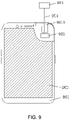
- the present application further provides a mobile terminal, referring to FIG. 9 , which includes a terminal main body 901, a display component 902, and a separable camera component 903.
- the terminal main body 901 includes the display component 902.
- the terminal main body 901 is provided with a receiving groove 9010.
- the receiving groove 8010 receives the separable camera component 903.
- the separable camera component 903 is in communication with the terminal main body 901.
- the separable camera component 903 is moveable out of the receiving groove 9010 to be separated from the terminal main body 901.
- the separable camera component 903 is wirelessly connected to the terminal main body 901 through a wireless module (not shown), or the separable camera component 903 is wiredly connected to the terminal main body 901 through a wired connection component.
- the wireless module can be wireless communication module such as WIFI, Bluetooth, or zigbee, which is not limited herein.
- the separable camera component 903 When the separable camera component 903 is moved out of the receiving groove 9010, it can be separated from the terminal main body 901, and the separable camera component 903 can be placed arbitrarily within a coverage of wireless communication.
- the following takes a wired connection between the separable camera component 903 and the terminal main body 901 as an example for description.
- the mobile terminal further includes a wired connection component 904 and a system motherboard 905.
- the receiving groove 9010 receives the wired connection component 904 and the separable camera component 903.
- the separable camera component 903 is electrically connected to the system motherboard 905 through the wired connection component 904.
- the system motherboard 905 is electrically connected to the display component 902.
- the separable camera component 903 is configured to extend from or be received in the receiving groove 9010 through the wired connection component 904, and is configured to be moved and/or rotated in a movable region of the wired connection component 904.
- the separable camera component 903 is configured to change a position and/or a photographing angle in the movable region of the wired connection component 904 by moving and/or twisting of the wired connection component 904.
- the wired connection component 904 includes a connecting wire and a flexible support. An end of the connecting wire is electrically connected to the system motherboard 905, and another end of the connecting wire is electrically connected to the separable camera component 903.
- the flexible support wraps the connecting wire, or the connecting wire is attached on a surface of the flexible support.
- the wired connection component 904 and the separable camera component 903 are same as/similar to the wired connection component and the separable camera component in the display device of the present application.
- a disposing method of the wired connection component 904 and the separable camera component 903 on the mobile terminal is same as/similar to a disposing method on the display device.
- a connecting method thereof, and a connecting method of the wired connection component 904 and the terminal main body 901 please refer to the description in the above display device, which is not repeated herein.
- the wired connection component 904 is a multi-stable support member that can replace a selfie stick.
- the separable camera component 903 can be separated from the terminal main body 901, and the support member can be used to adjust an angle of a selfie.
- the mobile terminal provided by the present application disposes the wired connection component between the system motherboard and the separable camera component, or adopts a wireless connection between the separable camera component and the terminal main body to replace a fixed camera component of a traditional mobile terminal by the separable camera component, which is flexible to use. This solves problems that limitations of positions and photographing angles of the present mobile terminals lead poor user experience and large power consumption of products.
- the separable camera component of the present application can be disposed on mobile terminals such as mobile phones and tablets, as well as other electronic devices and wearable devices, which is not limited herein.
- the display device, the electronic device, and the mobile terminal of the present application can be applied to a variety of different environments and places such as field surveys, construction sites, medical sites, and the like.
- the electronic device is taken as an example for description.
- FIG. 8 is a schematic diagram of a scenario where the electronic device provided by the present application is applied to an internal inspection of an instrument.
- the instrument 70 includes a small hole 702 (or a gap) on its outer shell.
- the component 701 to be inspected cannot be observed through the small hole 702 (or is not convenient for observation).
- the electronic device used for inspection cannot or is not convenient to enter an inside of the instrument 70 for inspection.
- the separable camera component 803 can be pulled out from the receiving groove 8010.
- the separable camera component 803 is fixed under a support of the wired connection component 804.
- the device main body 801 can be positioned relative to the separable camera component 803 by controlling parameters such as a stretch length and bending radius of the wired connection component 804.
- the wired connection component 804 further includes a rotating component 8041.
- the separable camera component 803 is hinged with the flexible support through the rotating component 8041.
- the separable camera component 803 includes a camera and a flash (not shown).
- the separable camera component 803 When the separable camera component 803 extends into the instrument 70 through the small hole 702, the separable camera component 803 realizes photographing at different angles through the rotating component 8041.
- the flash can be used to fill light, so as to implement inspection of the component 701 to be inspected inside the instrument 70.
- the display device, the electronic device, and the mobile terminal provided by the present application dispose the wired connection component between the system motherboard and the separable camera component, or adopts a wireless connection between the separable camera component and a main body to replace a traditional fixed camera component by the separable camera component.
- the separable camera component of the present application can be received in the receiving groove on the main body, and can be taken out of the receiving groove when in use.
- the separable camera component of the present application can be separated from the main body, so it is flexible to use. This solves problems that limitations of positions and photographing angles of the present display devices, electronic devices, and mobile terminals lead poor user experience and large power consumption of products.
Landscapes
- Engineering & Computer Science (AREA)
- Signal Processing (AREA)
- Multimedia (AREA)
- Human Computer Interaction (AREA)
- Studio Devices (AREA)
Abstract
Description
- The present application is related to the field of display technology, and specifically, to a display device, an electronic device, and a mobile terminal.
- Flexible organic light-emitting diode (OLED) display devices have good bendable performance and are lighter. Mobile terminals which are equipped with OLED display devices become more and more popular. Full-screen mobile phones have appeared on the market. One of the full-screen mobile phones adopts a lifting camera design which hides a camera inside a case. This design does not require camera under panel (CUP) technology; thus, its yield is higher. However, a direction of the lifting camera is fixed, which can only be used for photographing in one direction, so it is very inflexible. An internal lifting motor increases power consumption of a product.
- Therefore, the prior art has defects and needs to be urgently improved.
- The present application provides a display device, an electronic device, and a mobile terminal to solve problems that limitations of positions and photographing angles of the present display devices lead poor user experience and large power consumption of products.
- In order to solve the above problems, the present application provides technical solutions as follows.
- The present application provides a display device, including a device main body, a display component, and a separable camera component.
- The device main body includes the display component. The device main body is provided with a receiving groove. The receiving groove receives the separable camera component.
- The separable camera component is in communication with the device main body. The separable camera component is moveable out of the receiving groove to be separated from the device main body.
- In the display device of the present application, the separable camera component is wirelessly connected to the device main body through a wireless module.
- In the display device of the present application, the separable camera component is wiredly connected to the device main body through a wired connection component.
- In the display device of the present application, the device main body includes a housing and a system motherboard.
- The system motherboard is disposed in the housing. The separable camera component is electrically connected to the system motherboard through the wired connection component. The system motherboard is electrically connected to the display component.
- The receiving groove is disposed on the housing. The receiving groove receives the wired connection component and the separable camera component.
- The separable camera component is configured to extend from or be received in the receiving groove through the wired connection component, and is configured to be moved and/or rotated in a movable region of the wired connection component.
- In the display device of the present application, the separable camera component is configured to change a position and/or a photographing angle in the movable region of the wired connection component by moving and/or twisting of the wired connection component.
- In the display device of the present application, the wired connection component includes a connecting wire and a flexible support. An end of the connecting wire is electrically connected to the system motherboard, and another end of the connecting wire is electrically connected to the separable camera component. The flexible support wraps the connecting wire, or the connecting wire is attached on a surface of the flexible support.
- In the display device of the present application, the flexible support is a flexible sliding tube. The connecting wire is wrapped in the flexible sliding tube. The separable camera component is configured to extend from or be received in the receiving groove by stretching the flexible sliding tube, and is configured to change a position and/or a photographing angle by bending and/or twisting of the flexible sliding tube.
- In the display device of the present application, a stretch length of the flexible sliding tube is less than or equal to a length of the connecting wire.
- In the display device of the present application, the wired connection component further includes a rotating mechanism. The flexible support is connected to the separable camera component through the rotating mechanism. The separable camera component is configured to in-situ rotate through the rotating mechanism.
- In the display device of the present application, the receiving groove includes a first receiving portion receiving the separable camera component and a second receiving portion receiving the wired connection component. The second receiving portion is disposed between the first receiving portion and the system motherboard. The first receiving portion and the second receiving portion are communicated with each other. The wired connection component is configured to extend from or be received in the receiving groove through the first receiving portion.
- The present application further provides an electronic device, including a device main body, a display component, and a separable camera component.
- The device main body includes the display component. The device main body is provided with a receiving groove. The receiving groove receives the separable camera component.
- The separable camera component is in communication with the device main body. The separable camera component is moveable out of the receiving groove to be separated from the device main body.
- In the electronic device of the present application, the separable camera component is wirelessly connected to the device main body through a wireless module; or the separable camera component is wiredly connected to the device main body through a wired connection component.
- In the electronic device of the present application, the device main body further includes a system motherboard. The receiving groove receives the wired connection component and the separable camera component.
- The separable camera component is electrically connected to the system motherboard through the wired connection component. The system motherboard is electrically connected to the display component.
- The separable camera component is configured to extend from or be received in the receiving groove through the wired connection component, and is configured to be moved and/or rotated in a movable region of the wired connection component.
- In the electronic device of the present application, the separable camera component is configured to change a position and/or a photographing angle in the movable region of the wired connection component by moving and/or twisting of the wired connection component.
- In the electronic device of the present application, the wired connection component includes a connecting wire and a flexible support. An end of the connecting wire is electrically connected to the system motherboard, and another end of the connecting wire is electrically connected to the separable camera component. The flexible support wraps the connecting wire, or the connecting wire is attached on a surface of the flexible support.
- The present application further provides a mobile terminal, including a terminal main body, a display component, and a separable camera component.
- The terminal main body includes the display component. The terminal main body is provided with a receiving groove. The receiving groove receives the separable camera component.
- The separable camera component is in communication with the terminal main body. The separable camera component is moveable out of the receiving groove to be separated from the terminal main body.
- In the mobile terminal of the present application, the separable camera component is wirelessly connected to the terminal main body through a wireless module; or the separable camera component is wiredly connected to the terminal main body through a wired connection component.
- In the mobile terminal of the present application, the terminal main body further includes a system motherboard. The receiving groove receives the wired connection component and the separable camera component.
- The separable camera component is electrically connected to the system motherboard through the wired connection component. The system motherboard is electrically connected to the display component.
- The separable camera component is configured to extend from or be received in the receiving groove through the wired connection component, and is configured to be moved and/or rotated in a movable region of the wired connection component.
- In the mobile terminal of the present application, the separable camera component is configured to change a position and/or a photographing angle in the movable region of the wired connection component by moving and/or twisting of the wired connection component.
- In the mobile terminal of the present application, the wired connection component includes a connecting wire and a flexible support. An end of the connecting wire is electrically connected to the system motherboard, and another end of the connecting wire is electrically connected to the separable camera component. The flexible support wraps the connecting wire, or the connecting wire is attached on a surface of the flexible support.
- The beneficial effects of the present application are: the present application changes conventional fixed camera components to separable camera components. The display devices/electronic devices/mobile terminals use wireless or wired connection to connect the separable camera components so that the separable camera components can be separated from the device main bodies. As a result, the problems of poor user experience and large power consumption of products caused by limitations of positions and photographing angles of the present display devices are solved.
- The following describes specific embodiments of the present application in detail with reference to the accompanying drawings, which will make technical solutions and other beneficial effects of the present application obvious.
-
FIG. 1 is a structural diagram of a first type of a display device provided by the present application. -
FIG. 2 is a partial view of an internal diagram of the first type of a display device provided by the present application. -
FIG. 3 is an assembly diagram of a separable camera component and a wired connection component provided by the present application. -
FIG. 4 is a structural diagram of a second type of the display device provided by the present application. -
FIG. 5 is a schematic diagram of a display device provided by a first embodiment of the present application in a small-sized display state. -
FIG. 6 is a schematic diagram of the display device provided by the first embodiment of the present application in a large-sized display state. -
FIG. 7 is a schematic diagram of a display device provided by a second embodiment of the present application in an expanded state. -
FIG. 8 is a schematic diagram of a scenario where an electronic device provided by the present application is applied to an internal inspection of an instrument. -
FIG. 9 is a partial view of a cross-sectional diagram of a mobile terminal provided by the present application. - The technical solution of the present application embodiment will be clarified and completely described with reference accompanying drawings in embodiments of the present application embodiment. Obviously, the present application described parts of embodiments instead of all of the embodiments. Based on the embodiments of the present application, other embodiments which can be obtained by a skilled in the art without creative efforts fall into the protected scope of the of the present application.
- In the description of the present application, it should be noted that the terms "center", "portrait", "transverse", "length", "width", "thickness", "upper", "lower", "front", The directions or positional relationships indicated by "back", "left", "right", "vertical", "horizontal", "top", "bottom", "inside", "outside", etc. are based on the drawings. The orientation or positional relationship is only for the convenience of describing the present application and simplifying the description, and does not indicate or imply that the device or element referred to must have a specific orientation, structure and operation in a specific orientation, and should not be viewed as limitations of the present application. In addition, terms "first" and "second" are used for descriptive purposes only, and cannot be understood as indicating or implying relative importance or implicitly indicating the number of technical features indicated. Therefore, the features defined as "first" and "second" may explicitly or implicitly include one or more of the features. In the description of the present application, the meaning of "multiple" is two or more, unless specifically defined otherwise.
- In the description of the present application, it should be noted that terms "installation", "link", and "connection" should be understood broadly, unless explicitly stated and limited otherwise. For example, connection can be fixed connection or removable or integral connection, can be mechanical connection, electrical connection or mutual communication, can be direct connection or indirect connection through an intermedium, or can be the internal communication between two components or the mutual reaction between two components. For a skilled person in the art, the specific meanings of the above terms of the present application can be understood according to practical situations.
- In the present application, unless explicitly stated and limited, the first feature is "on" or "under" the second feature may refer to that the first feature and second feature are directly contact, or are indirectly through another feature between them. Moreover, the first feature is "above", "upon", and "upper" the second feature, including that the first feature is directly above and obliquely above the second feature refers to that t the first feature is higher in level than the second feature. The first feature is "below", "down", and "under" of the second feature refers to that the first feature is directly below or obliquely below the second feature, or merely refers to that the first feature is horizontally lower than the second feature. In the present application, "/" means "or".
- The following application provides many different embodiments or examples for implementing different structures of the present application. To simplify the application of the present application, the components and settings of specific examples are described below. Obviously, these are merely examples instead of limitation of the present application. Furthermore, the present application may repeat reference numbers and/or reference letters in different examples, and such repetition is for the purpose of simplicity and clarity, and does not indicate the relationship between the various embodiments and/or settings.
- The present application focus on technical problems that limitations of positions and photographing angles of the present display devices lead poor user experience and large power consumption of products. This embodiment can solve these defects.
- Please refer to
FIGs. 1 and 2. FIG. 1 is a structural diagram of a first type of a display device provided by the present application.FIG. 2 is a partial view of an internal diagram of the first type of the display device provided by the present application. The present application provides a devicemain body 10, adisplay component 2, aseparable camera component 3, and awired connection component 4. The devicemain body 10 includes ahousing 1, a system motherboard 5, and a power supply device. The devicemain body 10 includes thedisplay component 2. The system motherboard 5 is disposed in thehousing 1 and is electrically connected to thedisplay component 2. Theseparable camera component 3 is mechanically connected to thehousing 1 through thewired connection component 4. Theseparable camera component 3 is electrically connected to the system motherboard 5 through thewired connection component 4. - The
housing 1 is provided with a receivinggroove 100. The receivinggroove 100 receives thewired connection component 4 and theseparable camera component 3. Theseparable camera component 3 is configured to extend from or be received in the receivinggroove 100 through thewired connection component 4. An opening of the receivinggroove 100 needs to be disposed away from a region on an outer surface of thehousing 1 covered by thedisplay component 2, so as to prevent an extension of thewired connection component 4 and theseparable camera component 3 from an affecting of the opening of the receivinggroove 100 covered by thedisplay component 2. - The receiving
groove 100 includes afirst receiving portion 1001 receiving theseparable camera component 3 and asecond receiving portion 1002 receiving thewired connection component 4. Thefirst receiving portion 1001 and thesecond receiving portion 1002 are communicated with each other. Thesecond receiving portion 1002 is disposed between thefirst receiving portion 1001 and the system motherboard 5. Thewired connection component 4 is configured to extend from or be received in the receivinggroove 100 through thefirst receiving portion 1001. - A shape of the
first receiving portion 1001 matches a shape of theseparable camera component 3. Size of thefirst receiving portion 1001 is slightly larger than size of theseparable camera component 3, so theseparable camera component 3 can be smoothly embedded in thefirst receiving portion 1001. - A shape and size of the
second receiving portion 1002 are not specifically required, as long as it can receive thewired connection component 4. In an embodiment of the present application, thesecond receiving portion 1002 may not be provided, but thewired connection component 4 can be directly received in an internal storage space in thehousing 1 through a through hole in thefirst receiving portion 1001. In addition, the internal storage space in thehousing 1 is further provided with other devices such as a battery, which is not limited herein. - In an embodiment of the present application, the
second receiving portion 1002 is provided with a guiding structure (not shown), which can guide thewired connection component 4 of the second receiving portion 102 during receiving thewired connection component 4, so as to arrange it neatly to prevent a use of theseparable camera component 3 from affecting by "knotting" and "stuck" of thewired connection component 4. - When the
separable camera component 3 and thewired connection component 4 are received in the receivinggroove 100, theseparable camera component 3 can be engaged with the receivinggroove 100 to fix theseparable camera component 3 on thehousing 1. Theseparable camera component 3 can fill a gap of a surface of thehousing 1 formed by the receivinggroove 100. Meanwhile, thewired connection component 4 is hidden in a cavity surround by theseparable camera component 3 and the receivinggroove 100. Because theseparable camera component 3 and thewired connection component 4 are embedded in the receivinggroove 100, they do not occupy a display region and an extra space of the display device. - In this way, the
separable camera component 3 is used to photograph an object facing a surface of theseparable camera component 3 contacting outside, which means that a single-direction and a fixed-angle photograph at a fixed position is achieved without moving the display device; or theseparable camera component 3 cannot perform photographing. - When the
separable camera component 3 and thewired connection component 4 extend from the receivinggroove 100, theseparable camera component 3 can be separated from thehousing 1 and moved and/or rotated in a movable region of thewired connection component 4 by moving and/or twisting of thewired connection component 4, that is, theseparable camera component 3 changes a position and/or a photographing angle in the movable region of thewired connection component 4. - The
wired connection component 4 can be moved relative to thehousing 1 in its movable region, and thewired connection component 4 itself can also realize twisting. Theseparable camera component 3 can be moved and rotated relative to thehousing 1 under a traction of thewired connection component 4. - Specifically, when the
wired connection component 4 is moved relative to thehousing 1, the position of theseparable camera component 3 related to thehousing 1 changes. When thewired connection component 4 is twisted relative to thehousing 1, the photographing angle of theseparable camera component 3 changes, which can realize 360-degree free rotation around a certain direction. When thewired connection component 4 is moved and twisted relative to thehousing 1, theseparable camera component 3 realize an all-round photographing without any blind spots. - The
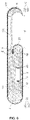
wired connection component 4 includes a connecting wire and a flexible support. An end of the connecting wire is electrically connected to the system motherboard 5, and another end of the connecting wire is electrically connected to theseparable camera component 3. The flexible support wraps the connecting wire, or the connecting wire is attached on a surface of the flexible support. - Specifically, as shown in
FIG. 3 , which is an assembly diagram of the separable camera component and the wired connection component provided by the present application, theseparable camera component 3 includes acamera 31. The flexible support of thewired connection component 4 is a flexible slidingtube 41. The connectingwire 42 is wrapped in the flexible slidingtube 41. The connectingwire 42 is wrapped with an insulating and protective tape such as an acetate tape. The flexible slidingtube 41 can be stretched, bent, and twisted and has protection and shaping functions, which can be bent/moved arbitrarily in its movable region and maintain a certain state. The flexible slidingtube 41 guides and includes the connectingwire 42, and it can be a flexible tube or a sleeve having shaping and supporting functions, which is not limited herein. - A stretch length of the flexible sliding
tube 41 is less than or equal to a length of the connectingwire 42 to prevent the connectingwire 42 from a risk of breakage due to a length of the connectingwire 42 being too short while stretching the flexible slidingtube 41. - In an embodiment, the stretch length of the flexible sliding
tube 41 ranges from 1 to 100 mm. The length of the connectingwire 42 ranges from 1 to 500 mm. - An end of the flexible sliding
tube 41 is fixed to the housing in the receiving groove, and another end thereof is fixed to theseparable camera component 3. Theseparable camera component 3 is configured to extend from or be received in the receiving groove by stretching the flexible slidingtube 41, and is configured to change a position and/or a photographing angle by bending and/or twisting of the flexible slidingtube 41. - In another embodiment, the
wired connection component 4 further includes arotating mechanism 43. As shown in the figure, the flexible slidingtube 41 is hinged with theseparable camera component 3 through therotating mechanism 43. Theseparable camera component 3 is configured to in-situ rotate through therotating mechanism 43. Therotating mechanism 43 includes but is not limited to a ball hinge mechanism. - As shown in
FIG. 4 , which is a structural diagram of a second type of the display device provided by the present application, the display device includes a devicemain body 10, adisplay component 2, and aseparable camera component 3. The devicemain body 10 includes ahousing 1 and a power supply device. Thehousing 1 is provided with a receivinggroove 100. The receivinggroove 100 receives theseparable camera component 3. - The device
main body 10 includes thedisplay component 2. Theseparable camera component 3 is wirelessly connected to the devicemain body 10. Specifically, theseparable camera component 3 is wirelessly connected to the devicemain body 10 through a wireless module (not shown). - The wireless module can be wireless communication module such as WIFI, Bluetooth, or zigbee, which is not limited herein.
- When the
separable camera component 3 is moved out of the receivinggroove 100, it can be separated from the devicemain body 10, and theseparable camera component 3 can be placed arbitrarily within a coverage of wireless communication. - The display device provided by the present application disposes the wired connection component between the system motherboard and the separable camera component, or adopts a wireless connection between the separable camera component and the device main body to replace a fixed camera component of a traditional display device by the separable camera component, which is flexible to use. This solves problems that limitations of positions and photographing angles of the present display devices lead poor user experience and large power consumption of products.
- The separable camera component of the present application can be applied to various types of display devices. A wired connection is taken as an example, and the display device of the present application is described in detail below with reference to specific embodiments.
- This embodiment disposes the separable camera component and the wired connection component on an extendable display device. As shown in
FIG. 5 , which is a schematic diagram of a display device provided by the first embodiment of the present application in a small-sized display state. The display device includes ahousing 1, adisplay component 2, aseparable camera component 3, a wired connection component 4 (as shown inFIG. 2 ), a system motherboard 5 (as shown inFIG. 5 ), and arotating component 6. Thehousing 1 includes afirst housing 11 and asecond housing 12, which are opposite to each other. Thefirst housing 11 includes afirst grid structure 111 and a first housingmain body 112. Thesecond housing 12 includes asecond grid structure 121 and a second housingmain body 122. Thefirst grid structure 111 and thesecond grid structure 121 are disposed in a staggered manner to compensate each other. Thefirst casing 11 and thesecond casing 12 realize relative movement through mutual compensation of thefirst grid structure 111 and thesecond grid structure 121. - The
rotating component 6 includes afirst pulley 61 and asecond pulley 62, whose axial directions are perpendicular to a moving direction of thefirst housing 11 and thesecond housing 12. Thefirst grid structure 111 and thesecond grid structure 121 both form a gap with the first housingmain body 112. Thefirst housing 11 and thesecond housing 12 cooperate to form a receivingcavity 7. Anopening channel 8 is formed between the first housingmain body 112 and the second housingmain body 122. Thedisplay component 2 bypasses an upper surface of thehousing 1 and lower surfaces of thefirst pulley 61 and thehousing 1 from a side of theopening channel 8 away from thesecond pulley 62, and then extends to the receivingcavity 7 from an opposite side of theopening channel 8. - A side wall of the first housing
main body 112 is provided with a receivinggroove 100. The system motherboard is disposed inside the first housingmain body 112. Theseparable camera component 3 can be received in the receivinggroove 100. The system motherboard is electrically connected to theseparable camera component 3 through the wired connection component. Theseparable camera component 3 can extend or be received in the receivinggroove 100 by stretching the wired connection component, which can be shown inFIG. 2 .FIG. 5 shows a state that theseparable camera component 3 and the wired connection component are received in the receivinggroove 100. - In this embodiment, the
housing 1 is provided with abuckle 200 at an opening of the receivinggroove 100. Thebuckle 200 is in an opened state when theseparable camera component 3 extends out of the receivinggroove 100. Thebuckle 200 is in a closed state when theseparable camera component 3 is received in the receivinggroove 100. Of course, it is not limited to this, theseparable camera component 3 can also be fixed to thehousing 1 through other ways. - In this embodiment, the
display component 2 includes anextension portion 20 in the receivingcavity 7. An end of thedisplay component 2 provided with theextension portion 20 is bonded to an end of thesecond grid structure 121 close to thefirst pulley 61 through a first bonding position A. An opposite end of thedisplay component 2 is bonded to a side surface of the second housingmain body 122 away from thesecond pulley 62 through the second bonding position B. - When the
second housing 12 is moved away from thefirst housing 11, theextension portion 20 of thedisplay component 2 is sent out of the receivingcavity 7 under a force (pushing force) of thesecond housing 12 at the first bonding position A due to a movement of thesecond housing 12. Meanwhile, an opposite end of thedisplay component 2 is pulled out under a force (tension force) at the second bonding position B due to the movement of thesecond housing 12. This thus realizes a transition of the display device from the small-sized display state to a large-size display state, as shown inFIG. 6 . A transition of the display device from the large-size display state to the smallsize display state is a reverse of the above description, which is not repeated herein. - The
separable camera component 3 can extend or be received in the receivinggroove 100 by stretching the wired connection component, and can be moved and/or rotated in a movable region of thewired connection component 4, which realizes a flexible change of a position and a photographing angle, so as to solve problems that limitations of positions and photographing angles of the present display devices lead poor user experience and large power consumption of products. - The
separable camera component 3 can also be disposed on the display device of this embodiment through a wireless connection, which is not repeated herein. - This embodiment is similar to the first embodiment described above, except that this embodiment disposes the separable camera component and the wired connection component on a foldable display device, as shown in
FIG. 7 , which is a schematic diagram of a display device provided by the second embodiment of the present application in an expanded state. The display device includes ahousing 1, adisplay component 2, aseparable camera component 3, a wired connection component 4 (as shown inFIG. 2 ), a system motherboard 5 (as shown inFIG. 2 ), and arotating component 6. - The display device includes a bending
portion 1A andnon-bending portions 1B on two sides of the bendingportion 1A. Thenon-bending portions 1B can be folded inward or outward through the bendingportion 1A. Thedisplay component 2 is disposed on a side surface of thehousing 1. A side wall of thehousing 1 is provided with a receivinggroove 100. The receivinggroove 100 is correspondingly disposed on thenon-bending portion 1B. - The
separable camera component 3 can be received in the receivinggroove 100. The system motherboard is electrically connected to theseparable camera component 3 through the wired connection component. Theseparable camera component 3 can extend or be received in the receivinggroove 100 by stretching the wired connection component, which can be shown inFIG. 2 . The figure of this embodiment shows a state that theseparable camera component 3 and the wired connection component are received in the receivinggroove 100. - The
separable camera component 3 can extend or be received in the receivinggroove 100 by stretching the wired connection component, and can be moved and/or rotated in a movable region of thewired connection component 4, which realizes a flexible change of a position and a photographing angle, so as to solve problems that limitations of positions and photographing angles of the present display devices lead poor user experience and large power consumption of products. - The
separable camera component 3 can also be disposed on the display device of this embodiment through a wireless connection, which is not repeated herein. - The present application further provides an electronic device, referring to
FIG. 8 , which includes a devicemain body 801, adisplay component 802, and aseparable camera component 803. The devicemain body 801 includes thedisplay component 802. The devicemain body 801 is provided with a receivinggroove 8010. The receivinggroove 8010 receives theseparable camera component 803. Theseparable camera component 803 is in communication with the devicemain body 801. Theseparable camera component 803 is moveable out of the receivinggroove 8010 to be separated from the devicemain body 801. - The
separable camera component 803 is wirelessly connected to the devicemain body 801 through a wireless module (not shown), or theseparable camera component 803 is wiredly connected to the devicemain body 801 through a wired connection component. - The wireless module can be wireless communication module such as WIFI, Bluetooth, or zigbee, which is not limited herein.
- When the
separable camera component 803 is moved out of the receivinggroove 8010, it can be separated from the devicemain body 801, and theseparable camera component 803 can be placed arbitrarily within a coverage of wireless communication. - The following takes a wired connection between the
separable camera component 803 and the devicemain body 801 as an example for description. - The electronic device further includes a
wired connection component 804 and asystem motherboard 805. The receivinggroove 8010 receives thewired connection component 804 and theseparable camera component 803. - The
separable camera component 803 is electrically connected to thesystem motherboard 805 through thewired connection component 804. Thesystem motherboard 805 is electrically connected to thedisplay component 802. - The
separable camera component 803 is configured to extend from or be received in the receivinggroove 8010 through thewired connection component 804, and is configured to be moved and/or rotated in a movable region of thewired connection component 804. - Specifically, the
separable camera component 803 is configured to change a position and/or a photographing angle in the movable region of thewired connection component 804 by moving and/or twisting of thewired connection component 804. - The
wired connection component 804 includes a connecting wire and a flexible support. An end of the connecting wire is electrically connected to thesystem motherboard 805, and another end of the connecting wire is electrically connected to theseparable camera component 803. The flexible support wraps the connecting wire, or the connecting wire is attached on a surface of the flexible support. - The
wired connection component 804 and theseparable camera component 803 are same as/similar to the wired connection component and the separable camera component in the display device of the present application. A disposing method of thewired connection component 804 and theseparable camera component 803 on the electronic device is same as/similar to a disposing method on the display device. For structures of thewired connection component 804 and theseparable camera component 803, a connecting method thereof, and a connecting method of thewired connection component 804 and the devicemain body 801, please refer to the description in the above display device, which is not repeated herein. - The electronic device provided by the present application disposes the wired connection component between the system motherboard and the separable camera component, or adopts a wireless connection between the separable camera component and the device main body to replace a fixed camera component of a traditional electronic device by the separable camera component, which is flexible to use. This solves problems that limitations of positions and photographing angles of the present electronic devices lead poor user experience and large power consumption of products.
- The present application further provides a mobile terminal, referring to
FIG. 9 , which includes a terminalmain body 901, adisplay component 902, and aseparable camera component 903. The terminalmain body 901 includes thedisplay component 902. The terminalmain body 901 is provided with a receivinggroove 9010. The receivinggroove 8010 receives theseparable camera component 903. Theseparable camera component 903 is in communication with the terminalmain body 901. Theseparable camera component 903 is moveable out of the receivinggroove 9010 to be separated from the terminalmain body 901. - The
separable camera component 903 is wirelessly connected to the terminalmain body 901 through a wireless module (not shown), or theseparable camera component 903 is wiredly connected to the terminalmain body 901 through a wired connection component. - The wireless module can be wireless communication module such as WIFI, Bluetooth, or zigbee, which is not limited herein.
- When the
separable camera component 903 is moved out of the receivinggroove 9010, it can be separated from the terminalmain body 901, and theseparable camera component 903 can be placed arbitrarily within a coverage of wireless communication. - The following takes a wired connection between the
separable camera component 903 and the terminalmain body 901 as an example for description. - As shown in
FIG. 9 , the mobile terminal further includes awired connection component 904 and asystem motherboard 905. The receivinggroove 9010 receives thewired connection component 904 and theseparable camera component 903. - The
separable camera component 903 is electrically connected to thesystem motherboard 905 through thewired connection component 904. Thesystem motherboard 905 is electrically connected to thedisplay component 902. - The
separable camera component 903 is configured to extend from or be received in the receivinggroove 9010 through thewired connection component 904, and is configured to be moved and/or rotated in a movable region of thewired connection component 904. - In the mobile terminal of the present application, the
separable camera component 903 is configured to change a position and/or a photographing angle in the movable region of thewired connection component 904 by moving and/or twisting of thewired connection component 904. - In the mobile terminal of the present application, the
wired connection component 904 includes a connecting wire and a flexible support. An end of the connecting wire is electrically connected to thesystem motherboard 905, and another end of the connecting wire is electrically connected to theseparable camera component 903. The flexible support wraps the connecting wire, or the connecting wire is attached on a surface of the flexible support. - The
wired connection component 904 and theseparable camera component 903 are same as/similar to the wired connection component and the separable camera component in the display device of the present application. A disposing method of thewired connection component 904 and theseparable camera component 903 on the mobile terminal is same as/similar to a disposing method on the display device. For structures of thewired connection component 904 and theseparable camera component 903, a connecting method thereof, and a connecting method of thewired connection component 904 and the terminalmain body 901, please refer to the description in the above display device, which is not repeated herein. - In an embodiment, the
wired connection component 904 is a multi-stable support member that can replace a selfie stick. When taking a selfie, theseparable camera component 903 can be separated from the terminalmain body 901, and the support member can be used to adjust an angle of a selfie. - The mobile terminal provided by the present application disposes the wired connection component between the system motherboard and the separable camera component, or adopts a wireless connection between the separable camera component and the terminal main body to replace a fixed camera component of a traditional mobile terminal by the separable camera component, which is flexible to use. This solves problems that limitations of positions and photographing angles of the present mobile terminals lead poor user experience and large power consumption of products.
- The separable camera component of the present application can be disposed on mobile terminals such as mobile phones and tablets, as well as other electronic devices and wearable devices, which is not limited herein.
- The display device, the electronic device, and the mobile terminal of the present application can be applied to a variety of different environments and places such as field surveys, construction sites, medical sites, and the like. The electronic device is taken as an example for description.
- As shown in
FIG. 8 , which is a schematic diagram of a scenario where the electronic device provided by the present application is applied to an internal inspection of an instrument. There is acomponent 701 to be inspected in theinstrument 70. Theinstrument 70 includes a small hole 702 (or a gap) on its outer shell. Thecomponent 701 to be inspected cannot be observed through the small hole 702 (or is not convenient for observation). Generally, the electronic device used for inspection cannot or is not convenient to enter an inside of theinstrument 70 for inspection. When the electronic device of the present application is used for inspection, theseparable camera component 803 can be pulled out from the receivinggroove 8010. Theseparable camera component 803 is fixed under a support of thewired connection component 804. The devicemain body 801 can be positioned relative to theseparable camera component 803 by controlling parameters such as a stretch length and bending radius of thewired connection component 804. - The
wired connection component 804 further includes arotating component 8041. Theseparable camera component 803 is hinged with the flexible support through therotating component 8041. Theseparable camera component 803 includes a camera and a flash (not shown). - When the
separable camera component 803 extends into theinstrument 70 through thesmall hole 702, theseparable camera component 803 realizes photographing at different angles through therotating component 8041. The flash can be used to fill light, so as to implement inspection of thecomponent 701 to be inspected inside theinstrument 70. - In summary, the display device, the electronic device, and the mobile terminal provided by the present application dispose the wired connection component between the system motherboard and the separable camera component, or adopts a wireless connection between the separable camera component and a main body to replace a traditional fixed camera component by the separable camera component. The separable camera component of the present application can be received in the receiving groove on the main body, and can be taken out of the receiving groove when in use. The separable camera component of the present application can be separated from the main body, so it is flexible to use. This solves problems that limitations of positions and photographing angles of the present display devices, electronic devices, and mobile terminals lead poor user experience and large power consumption of products.
- In the above embodiments, descriptions for the embodiments emphasize different aspects, and for a part without being described in detail in a certain embodiment, reference may be made to related descriptions in other embodiments.
- The electronic device provided by embodiments of the present application is described in detail above, the specific examples of this document are used to explain principles and embodiments of the present application, and the description of embodiments above is only for helping to understand the present application. Persons of ordinary skill in the art should understand that they may still make modifications to the technical solutions described in the above embodiments or make equivalent replacements to some or all technical features thereof, without departing from the scope of the technical solutions of the embodiments of the present application.
Claims (20)
- A display device, comprising a device main body, a display component, and a separable camera component;wherein the device main body comprises the display component, the device main body is provided with a receiving groove, and the receiving groove receives the separable camera component; andwherein the separable camera component is in communication with the device main body, and the separable camera component is moveable out of the receiving groove to be separated from the device main body.
- The display device according to claim 1, wherein the separable camera component is wirelessly connected to the device main body through a wireless module.
- The display device according to claim 1, wherein the separable camera component is wiredly connected to the device main body through a wired connection component.
- The display device according to claim 3, wherein the device main body comprises a housing and a system motherboard;the system motherboard is disposed in the housing, the separable camera component is electrically connected to the system motherboard through the wired connection component, and the system motherboard is electrically connected to the display component;the receiving groove is disposed on the housing, and the receiving groove receives the wired connection component and the separable camera component; andthe separable camera component is configured to extend from or be received in the receiving groove through the wired connection component, and is configured to be moved and/or rotated in a movable region of the wired connection component.
- The display device according to claim 4, wherein the separable camera component is configured to change a position and/or a photographing angle in the movable region of the wired connection component by moving and/or twisting of the wired connection component.
- The display device according to claim 4, wherein the wired connection component comprises a connecting wire and a flexible support, an end of the connecting wire is electrically connected to the system motherboard, and another end of the connecting wire is electrically connected to the separable camera component; and
the flexible support wraps the connecting wire, or the connecting wire is attached on a surface of the flexible support. - The display device according to claim 6, wherein the flexible support is a flexible sliding tube, the connecting wire is wrapped in the flexible sliding tube, the separable camera component is configured to extend from or be received in the receiving groove by stretching the flexible sliding tube, and is configured to change a position and/or a photographing angle by bending and/or twisting of the flexible sliding tube.
- The display device according to claim 7, wherein a stretch length of the flexible sliding tube is less than or equal to a length of the connecting wire.
- The display device according to claim 6, wherein the wired connection component further comprises a rotating mechanism, the flexible support is connected to the separable camera component through the rotating mechanism, and the separable camera component is configured to in-situ rotate through the rotating mechanism.
- The display device according to claim 4, wherein the receiving groove comprises a first receiving portion receiving the separable camera component and a second receiving portion receiving the wired connection component, the second receiving portion is disposed between the first receiving portion and the system motherboard, the first receiving portion and the second receiving portion are communicated with each other, and the wired connection component is configured to extend from or be received in the receiving groove through the first receiving portion.
- An electronic device, comprising a device main body, a display component, and a separable camera component;wherein the device main body comprises the display component, the device main body is provided with a receiving groove, and the receiving groove receives the separable camera component; andwherein the separable camera component is in communication with the device main body, and the separable camera component is moveable out of the receiving groove to be separated from the device main body.
- The electronic device according to claim 11, wherein the separable camera component is wirelessly connected to the device main body through a wireless module; or
the separable camera component is wiredly connected to the device main body through a wired connection component. - The electronic device according to claim 12, wherein the device main body further comprises a system motherboard, and the receiving groove receives the wired connection component and the separable camera component;the separable camera component is electrically connected to the system motherboard through the wired connection component, and the system motherboard is electrically connected to the display component; andthe separable camera component is configured to extend from or be received in the receiving groove through the wired connection component, and is configured to be moved and/or rotated in a movable region of the wired connection component.
- The electronic device according to claim 13, wherein the separable camera component is configured to change a position and/or a photographing angle in the movable region of the wired connection component by moving and/or twisting of the wired connection component.
- The electronic device according to claim 13, wherein the wired connection component comprises a connecting wire and a flexible support, an end of the connecting wire is electrically connected to the system motherboard, and another end of the connecting wire is electrically connected to the separable camera component; and
the flexible support wraps the connecting wire, or the connecting wire is attached on a surface of the flexible support. - A mobile terminal, comprising a terminal main body, a display component, and a separable camera component;wherein the terminal main body comprises the display component, the terminal main body is provided with a receiving groove, and the receiving groove receives the separable camera component; andwherein the separable camera component is in communication with the terminal main body, and the separable camera component is moveable out of the receiving groove to be separated from the terminal main body.
- The mobile terminal according to claim 16, wherein the separable camera component is wirelessly connected to the terminal main body through a wireless module; or
the separable camera component is wiredly connected to the terminal main body through a wired connection component. - The mobile terminal according to claim 17, wherein the terminal main body further comprises a system motherboard, and the receiving groove receives the wired connection component and the separable camera component;the separable camera component is electrically connected to the system motherboard through the wired connection component, and the system motherboard is electrically connected to the display component; andthe separable camera component is configured to extend from or be received in the receiving groove through the wired connection component, and is configured to be moved and/or rotated in a movable region of the wired connection component.
- The mobile terminal according to claim 18, wherein the separable camera component is configured to change a position and/or a photographing angle in the movable region of the wired connection component by moving and/or twisting of the wired connection component.
- The mobile terminal according to claim 18, wherein the wired connection component comprises a connecting wire and a flexible support, an end of the connecting wire is electrically connected to the system motherboard, and another end of the connecting wire is electrically connected to the separable camera component; and
the flexible support wraps the connecting wire, or the connecting wire is attached on a surface of the flexible support.
Applications Claiming Priority (2)
| Application Number | Priority Date | Filing Date | Title |
|---|---|---|---|
| CN201911256047.3A CN111083257A (en) | 2019-12-10 | 2019-12-10 | Display device, electronic equipment and mobile terminal |
| PCT/CN2020/070601 WO2021114448A1 (en) | 2019-12-10 | 2020-01-07 | Display apparatus, electronic device and mobile terminal |
Publications (2)
| Publication Number | Publication Date |
|---|---|
| EP4075780A1 true EP4075780A1 (en) | 2022-10-19 |
| EP4075780A4 EP4075780A4 (en) | 2024-01-10 |
Family
ID=70313512
Family Applications (1)
| Application Number | Title | Priority Date | Filing Date |
|---|---|---|---|
| EP20737330.9A Withdrawn EP4075780A4 (en) | 2019-12-10 | 2020-01-07 | Display apparatus, electronic device and mobile terminal |
Country Status (4)
| Country | Link |
|---|---|
| US (1) | US20220131962A1 (en) |
| EP (1) | EP4075780A4 (en) |
| CN (1) | CN111083257A (en) |
| WO (1) | WO2021114448A1 (en) |
Families Citing this family (3)
| Publication number | Priority date | Publication date | Assignee | Title |
|---|---|---|---|---|
| CN111427422B (en) * | 2020-04-30 | 2024-06-18 | 合肥联宝信息技术有限公司 | Anti-slip pad and electronic equipment |
| CN111669454B (en) * | 2020-05-06 | 2021-08-24 | 维沃移动通信有限公司 | Electronic device |
| CN113014700B (en) * | 2021-02-09 | 2023-10-20 | 维沃移动通信有限公司 | Electronic equipment |
Family Cites Families (15)
| Publication number | Priority date | Publication date | Assignee | Title |
|---|---|---|---|---|
| CN2151357Y (en) * | 1993-05-11 | 1993-12-29 | 孔云 | Desk lamp with magnifier |
| US5801919A (en) * | 1997-04-04 | 1998-09-01 | Gateway 2000, Inc. | Adjustably mounted camera assembly for portable computers |
| US7957765B1 (en) * | 2007-05-25 | 2011-06-07 | At&T Mobility Ii Llc | Mobile phone with integrated wireless camera |
| CN102014244A (en) * | 2009-09-07 | 2011-04-13 | 纬创资通股份有限公司 | Portable electronic system with detachable camera module |
| CN102235611A (en) * | 2010-04-22 | 2011-11-09 | 襄樊学院 | Multifunctional desk lamp |
| US8711566B2 (en) * | 2011-09-02 | 2014-04-29 | Microsoft Corporation | Expandable mobile device |
| CN103248974A (en) * | 2012-02-13 | 2013-08-14 | 深圳富泰宏精密工业有限公司 | Electronic device with a built-in earphone |
| CN203024026U (en) * | 2013-01-31 | 2013-06-26 | 鸡西大学 | Special desk lamp for piano |
| CN203387549U (en) * | 2013-06-27 | 2014-01-08 | 上海酷宇通讯技术有限公司 | Full-angle shooting mobile phone |
| TWI548966B (en) * | 2014-12-29 | 2016-09-11 | 鴻海精密工業股份有限公司 | Electronic device |
| US10579108B2 (en) * | 2016-03-20 | 2020-03-03 | Case Cam LLC | Phone case with camera |
| CN207304652U (en) * | 2017-09-22 | 2018-05-01 | 深圳市金立通信设备有限公司 | A kind of mobile terminal shell structure and mobile terminal |
| CN108696688A (en) * | 2018-07-13 | 2018-10-23 | 维沃移动通信有限公司 | A kind of camera, terminal and image pickup method |
| CN208638405U (en) * | 2018-09-26 | 2019-03-22 | 四川长虹电器股份有限公司 | A kind of screen smart-phone device comprehensively |
| CN209659365U (en) * | 2019-05-28 | 2019-11-19 | 维沃移动通信有限公司 | Terminal device |
-
2019
- 2019-12-10 CN CN201911256047.3A patent/CN111083257A/en active Pending
-
2020
- 2020-01-07 US US16/954,525 patent/US20220131962A1/en not_active Abandoned
- 2020-01-07 WO PCT/CN2020/070601 patent/WO2021114448A1/en not_active Ceased
- 2020-01-07 EP EP20737330.9A patent/EP4075780A4/en not_active Withdrawn
Also Published As
| Publication number | Publication date |
|---|---|
| CN111083257A (en) | 2020-04-28 |
| WO2021114448A1 (en) | 2021-06-17 |
| EP4075780A4 (en) | 2024-01-10 |
| US20220131962A1 (en) | 2022-04-28 |
Similar Documents
| Publication | Publication Date | Title |
|---|---|---|
| EP4075780A1 (en) | Display apparatus, electronic device and mobile terminal | |
| US10425515B2 (en) | Mobile terminal and electronic apparatus | |
| CN1306784C (en) | Portable terminal | |
| US7636590B2 (en) | Self-cradling type portable communication terminal | |
| CN110442196A (en) | Rotating mechanism, Folding display terminal | |
| KR102382300B1 (en) | Display apparatus | |
| US20200322515A1 (en) | Image Capturing Assembly and Electronic Device | |
| KR20190094411A (en) | Flexible devices | |
| CN209710124U (en) | Electronic equipment | |
| CN114006961B (en) | Folding device and electronic device | |
| CN113949757B (en) | Folding device and electronic equipment | |
| KR20190094412A (en) | Flexible devices | |
| CN113364906B (en) | Functional component, mobile terminal and control method thereof | |
| KR20180115611A (en) | A wearable smart phone having a strap with a parallel-connected battery system | |
| WO2021098043A1 (en) | Flexible screen module, terminal device and photographing method | |
| CN109873886B (en) | Terminal device | |
| CN211123830U (en) | Rotating mechanism, folding display terminal | |
| CN208316360U (en) | mobile terminal charging device | |
| CN213457674U (en) | Intelligence wearing equipment with shoot finder | |
| CN113163038A (en) | Screen assembly and electronic equipment | |
| CN110380593A (en) | A kind of functional device and electronic equipment | |
| CN110062136B (en) | Electronic equipment | |
| WO2019228479A1 (en) | Image capture device and electronic apparatus | |
| CN108712632A (en) | Optical cable inspection tour system and inspection method in standing | |
| CN116504137A (en) | A display component and a display device |
Legal Events
| Date | Code | Title | Description |
|---|---|---|---|
| STAA | Information on the status of an ep patent application or granted ep patent |
Free format text: STATUS: UNKNOWN |
|
| STAA | Information on the status of an ep patent application or granted ep patent |
Free format text: STATUS: THE INTERNATIONAL PUBLICATION HAS BEEN MADE |
|
| PUAI | Public reference made under article 153(3) epc to a published international application that has entered the european phase |
Free format text: ORIGINAL CODE: 0009012 |
|
| STAA | Information on the status of an ep patent application or granted ep patent |
Free format text: STATUS: REQUEST FOR EXAMINATION WAS MADE |
|
| 17P | Request for examination filed |
Effective date: 20200717 |
|
| AK | Designated contracting states |
Kind code of ref document: A1 Designated state(s): AL AT BE BG CH CY CZ DE DK EE ES FI FR GB GR HR HU IE IS IT LI LT LU LV MC MK MT NL NO PL PT RO RS SE SI SK SM TR |
|
| DAV | Request for validation of the european patent (deleted) | ||
| DAX | Request for extension of the european patent (deleted) | ||
| REG | Reference to a national code |
Ref country code: DE Ref legal event code: R079 Free format text: PREVIOUS MAIN CLASS: H04N0005225000 Ipc: H04M0001020000 |
|
| A4 | Supplementary search report drawn up and despatched |
Effective date: 20231211 |
|
| RIC1 | Information provided on ipc code assigned before grant |
Ipc: H04M 1/72412 20210101ALN20231205BHEP Ipc: H04M 1/02 20060101AFI20231205BHEP |
|
| STAA | Information on the status of an ep patent application or granted ep patent |
Free format text: STATUS: EXAMINATION IS IN PROGRESS |
|
| 17Q | First examination report despatched |
Effective date: 20250722 |
|
| STAA | Information on the status of an ep patent application or granted ep patent |
Free format text: STATUS: THE APPLICATION IS DEEMED TO BE WITHDRAWN |
|
| 18D | Application deemed to be withdrawn |
Effective date: 20251125 |