EP4075718B1 - Selbstsynchronisierungsmodus für einen verschlüsselungs- und entschlüsselungsalgorithmus - Google Patents
Selbstsynchronisierungsmodus für einen verschlüsselungs- und entschlüsselungsalgorithmus Download PDFInfo
- Publication number
- EP4075718B1 EP4075718B1 EP22166111.9A EP22166111A EP4075718B1 EP 4075718 B1 EP4075718 B1 EP 4075718B1 EP 22166111 A EP22166111 A EP 22166111A EP 4075718 B1 EP4075718 B1 EP 4075718B1
- Authority
- EP
- European Patent Office
- Prior art keywords
- ciphertext
- cryptographic
- cryptographic algorithm
- bits
- bit
- Prior art date
- Legal status (The legal status is an assumption and is not a legal conclusion. Google has not performed a legal analysis and makes no representation as to the accuracy of the status listed.)
- Active
Links
Images







Classifications
-
- H—ELECTRICITY
- H04—ELECTRIC COMMUNICATION TECHNIQUE
- H04L—TRANSMISSION OF DIGITAL INFORMATION, e.g. TELEGRAPHIC COMMUNICATION
- H04L9/00—Cryptographic mechanisms or cryptographic arrangements for secret or secure communications; Network security protocols
- H04L9/06—Cryptographic mechanisms or cryptographic arrangements for secret or secure communications; Network security protocols the encryption apparatus using shift registers or memories for block-wise or stream coding, e.g. DES systems or RC4; Hash functions; Pseudorandom sequence generators
- H04L9/0618—Block ciphers, i.e. encrypting groups of characters of a plain text message using fixed encryption transformation
- H04L9/0637—Modes of operation, e.g. cipher block chaining [CBC], electronic codebook [ECB] or Galois/counter mode [GCM]
-
- H—ELECTRICITY
- H04—ELECTRIC COMMUNICATION TECHNIQUE
- H04L—TRANSMISSION OF DIGITAL INFORMATION, e.g. TELEGRAPHIC COMMUNICATION
- H04L9/00—Cryptographic mechanisms or cryptographic arrangements for secret or secure communications; Network security protocols
- H04L9/06—Cryptographic mechanisms or cryptographic arrangements for secret or secure communications; Network security protocols the encryption apparatus using shift registers or memories for block-wise or stream coding, e.g. DES systems or RC4; Hash functions; Pseudorandom sequence generators
- H04L9/0618—Block ciphers, i.e. encrypting groups of characters of a plain text message using fixed encryption transformation
- H04L9/0631—Substitution permutation network [SPN], i.e. cipher composed of a number of stages or rounds each involving linear and nonlinear transformations, e.g. AES algorithms
-
- H—ELECTRICITY
- H04—ELECTRIC COMMUNICATION TECHNIQUE
- H04L—TRANSMISSION OF DIGITAL INFORMATION, e.g. TELEGRAPHIC COMMUNICATION
- H04L9/00—Cryptographic mechanisms or cryptographic arrangements for secret or secure communications; Network security protocols
- H04L9/06—Cryptographic mechanisms or cryptographic arrangements for secret or secure communications; Network security protocols the encryption apparatus using shift registers or memories for block-wise or stream coding, e.g. DES systems or RC4; Hash functions; Pseudorandom sequence generators
- H04L9/065—Encryption by serially and continuously modifying data stream elements, e.g. stream cipher systems, RC4, SEAL or A5/3
- H04L9/0656—Pseudorandom key sequence combined element-for-element with data sequence, e.g. one-time-pad [OTP] or Vernam's cipher
- H04L9/0662—Pseudorandom key sequence combined element-for-element with data sequence, e.g. one-time-pad [OTP] or Vernam's cipher with particular pseudorandom sequence generator
-
- H—ELECTRICITY
- H04—ELECTRIC COMMUNICATION TECHNIQUE
- H04L—TRANSMISSION OF DIGITAL INFORMATION, e.g. TELEGRAPHIC COMMUNICATION
- H04L9/00—Cryptographic mechanisms or cryptographic arrangements for secret or secure communications; Network security protocols
- H04L9/12—Transmitting and receiving encryption devices synchronised or initially set up in a particular manner
-
- H—ELECTRICITY
- H04—ELECTRIC COMMUNICATION TECHNIQUE
- H04L—TRANSMISSION OF DIGITAL INFORMATION, e.g. TELEGRAPHIC COMMUNICATION
- H04L2209/00—Additional information or applications relating to cryptographic mechanisms or cryptographic arrangements for secret or secure communication H04L9/00
- H04L2209/12—Details relating to cryptographic hardware or logic circuitry
Definitions
- This document relates generally to cryptographic systems. More particularly, this document relates to systems and methods for a self-synchronizing mode of operation.
- the cryptographic algorithm implements a method that generally involves: combining a cryptographic key with state initialization bits to generate first combination bits; producing a first keystream by performing a permutation function f using the first combination bits as inputs thereto; and using the first keystream to encrypt first data (e.g., authentication data or message body data) so as to produce first encrypted data (e.g., via modular arithmetic).
- the permutation function f comprises a round function f round that is iterated R times.
- the round function f round consists of (1) a substitution layer in which the first combination bits are substituted with substitute bits, (2) a permutation layer in which the substitute bits are re-arranged, (3) a mixing layer in which at least two outputs of the permutation layer are combined together, and (4) an addition layer in which a constant is added to the output of the mixing layer.
- a block cipher device for a cryptographically secured digital communication system includes a pair of first stages connected in parallel for receiving an input data block and a control data block. Each first stage defines a respective first data path and includes a sum modulo-two unit for receiving the control data block and the input data block. Each first stage also includes a first nibble swap unit downstream from the sum modulo-two unit. A key scheduler generates a random key data block based upon a received key data block. A pair of second stages is connected in parallel downstream from the first stages and receives the random key data block, the control data block and output signals from the first stages for providing an output data block.
- Document XP055953193 proposes two modes of operation for block ciphers, referred to as statistical cipher feedback (SCFB) mode and optimized cipher feedback (OCFB) mode, are investigated. Both cipher modes have the capability of self-synchronization with high efficiency. In particular, the paper studies the performance of SCFB mode and OCFB mode with respect to characteristics such as the theoretical efficiency, the synchronization recovery delay (SRD), and the error propagation factor (EPF).
- Document XP037019733 discloses development history of stream ciphers, classifies and summarizes the design principles of typical stream ciphers in groups, briefly discusses the advantages and weakness of various stream ciphers in terms of security and implementation .
- sponge construction which uses a wide random permutation, and allows inputting and outputting any amount of data, which leads to great flexibility.
- document discloses duplex structure and a fixed permutation of iterative functions with SPN structure.
- a result from combining the plaintext with a keystream block is used as the bitrate portion of the initialization value for a cryptographic algorithm when a determination is made that the given sequence of values does not exist within the ciphertext.
- the cryptographic algorithm may include, but is not limited to, an adaption of a sponge construction framework.
- the adaptation of the sponge construction framework may include, but is not limited to, a duplex construction in which a permutation function is iteratively performed.
- the ciphertext may be generated by the cryptographic system in accordance with the cryptographic algorithm or received from a remote device that generated the ciphertext.
- the synchronized cryptographic algorithm is used to decrypt the ciphertext or to encrypt plaintext.
- the implementing systems comprise digital logic circuits with logic/state devices.
- the implementing systems comprise: a processor; and a non-transitory computer-readable medium comprising programming instructions that are configured to cause the processor to implement a method for operating a cryptographic algorithm.
- the programming instructions comprise instructions to: obtain ciphertext by the cryptographic system; perform operations by the cryptographic system to determine whether a given sequence of values exits within the ciphertext; and synchronize the cryptographic system with another cryptographic system using the ciphertext as a bitrate portion of an initialization value for a cryptographic algorithm and zero as a capacity portion of the initialization value for the cryptographic algorithm, when a determination is made that the given sequence of values exist within the ciphertext.
- the programming instructions may also comprise instructions to cause the processor to use results from combining the plaintext with a keystream block as the bitrate portion of the initialization value for a cryptographic algorithm when a determination is made that the given sequence of values does not exist within the ciphertext.
- the present solution also has the following additional advantages: increased processing performance and provable computational cryptographic strength; cost effective alternative to embedded sovereign cryptography; includes cryptographic constructs and key lengths to provide post quantum security in a reasonable hardware and software footprint; and designed against a military threat model.
- FIG. 1 there is provided a schematic illustration of an illustrative architecture for a sponge construction 100 implementing the present solution.
- the sponge construction 100 uses a unique permutation function f (described below) to provide the traditional suite of cryptographic modes. This will become more evident as the discussion progresses.
- the sponge construction 100 is generally designed to implement symmetric cryptography functionalities, namely key derivation and message encryption/decryption.
- the sponge construction 100 is a simple iterated construction for building a function F based on a unique permutation function f
- the function F has a variable-length input and an arbitrary output length.
- the capacity c determines the security level of the sponge construction.
- the sponge construction 100 can be implemented in hardware, software or a combination of both hardware and software.
- the operations of each functional block 102-106 may be implemented using hardware and/or software.
- the hardware can include, but is not limited to an electronic circuit.
- the electronic circuit can include passive components, active components and logical components.
- the sponge construction 100 is divided into two phases.
- the first phase is an absorbing phase 120 in which the cryptographic key K or K ⁇ N (i.e., a concatenation of the cryptographic key K and a flag N ) is absorbed into a state of the sponge construction 100 while interleaving with applications of the underlying permutation function f .
- Such absorption is achieved by combining K (or K ⁇ N ) with the first r bits of the initialized state bits b.
- the bits b e.g., 512 bits
- the present solution is not limited in this regard.
- the bits b (e.g., 512 bits) may alternatively be initialized to any bit value (e.g., any 512 bit value). As such, each user could generate its own unique value to set during the initialization phase.
- K or K ⁇ N
- XOR exclusive OR
- XOR operations are well known in the art, and therefore will not be described in detail here. Still, it should be understood that the XOR operations are performed on a bit-by-bit basis. The result of each XOR operation is true whenever an odd number of inputs are true and false whenever an even number of inputs are true. The results of the XOR operations are then passed to permutation functional block 102 where the results are interleaved with applications of the unique permutation function f .
- the second phase is a squeezing phase 122 in which keystream blocks Z 0 , Z 1 , Z 2 are produced by the performance of the unique permutation function f in permutation functional blocks 102-106.
- Each keystream block Z 0 , Z 1 , Z 2 comprises r bits.
- the unique permutation function f will be described in detail below. Still, it should be understood that the permutation function f maps each possible value of the bits input thereto into a particular unique value of the output bits.
- permutation functional block 102 takes the output of the absorbing phase 120 as an input.
- Permutation functional block 104 takes the output of permutation functional block 102 as an input.
- Permutation functional block 106 takes the output of permutation functional block 104 as an input.
- the encrypted data block can include, but is not limited to, a ciphertext block C 0 , C 1 or C 2 .
- the present solution is described herein in relation to ciphertext.
- the present solution is not limited in this regard.
- the present solution can be used to encrypt any type of data (e.g., text, audio, video, etc).
- each keystream block Z 0 , Z 1 , Z 2 is combined with a respective block of message bits M 0 , M 1 , M 2 via modulo 2 addition.
- the modulo 2 addition can be implemented using an XOR operation, as shown in FIG. 1 .
- the XOR operation is performed on a bit-by-bit basis.
- a first bit m 0 of a message block M 0 , M 1 or M 2 is combined with a first bit z 0 of a respective keystream block Z 0 , Z 1 or Z 2 via modulo 2 addition.
- a second bit m 1 of a message block M 0 , M 1 or M 2 is combined with a first bit z 1 of a respective keystream block Z 0 , Z 1 or Z 2 via modulo 2 addition, and so on.
- the duplex construction 200 can be implemented in hardware, software or a combination of both hardware and software.
- the operations of each component 202-232 may be implemented using hardware and/or software.
- the hardware can include, but is not limited to an electronic circuit.
- the electronic circuit can include passive components, active components and logical components.
- the duplex construction 200 the absorbing phase and squeezing phase are combined into each of a plurality of duplex operations. Accordingly, the duplex construction 200 comprises a plurality of duplex objects 202-206. The operations of each duplex object will be described separately below. Notably, the state of each duplex object call is preserved.
- the input to duplex object 202 is a cryptographic key K (or optionally K ⁇ 1 , i.e. a concatenation of the cryptographic key K and a flag 1 ).
- the cryptographic key K (or optionally K ⁇ 1 ) is padded in padding functional block 214 to make it a multiple of r (if it is not a multiple of r ).
- the padding can involve appending bits to the beginning or end of the cryptographic key K (or optionally K ⁇ 1 ).
- the output of padding functional block 214 is then combined at 226 with the first r bits of the initialized state bits b.
- the present solution is not limited in this regard.
- the bits A (e.g., 512 bits) may alternatively be initialized to any bit value (e.g., a 512 bit value). As such, each user could generate its own unique value to set during the initialization phase.
- the input to duplex object 204 is authentication data A (or optionally A ⁇ 0 , i.e. a concatenation of authentication data A and a flag 0 ).
- the authentication data A can include but is not limited to, authenticated packet headers.
- the authentication data A (or optionally A ⁇ 0 ) is padded in padding functional block 216 to make it a multiple of r (if it is not a multiple of r ).
- the padding of padding functional block 216 is the same as or similar to that of padding functional block 214.
- the output of padding functional block 216 is then combined with keystream block Z 0 . This combining can be achieved via XOR operations 228, as shown in FIG. 2 .
- XOR operations are well known in the art, and therefore will not be described in detail here. Still, it should be understood that the XOR operations are performed on a bit-by-bit basis.
- the results of the XOR operations are then passed to permutation functional block 210.
- permutation functional block 210 the unique permutation function f is performed so as to generate a keystream block Z 1 .
- the keystream block Z 1 is then optionally truncated to a desired length l , as shown by truncate functional block 222.
- the value of l here can be less than r . Truncation may be performed when the number of bits contained in the message body B is less than r. In this case, the value of l equals the number of bits contained in the message body B.
- the truncated keystream block Z 1-Trunc is output from duplex object 204.
- the XOR operations are performed on a bit-by-bit basis.
- the results of the XOR operations are then passed to permutation functional block 212.
- permutation functional block 212 the unique permutation function f is performed so as to generate a keystream block Z 2 .
- the keystream block Z 2 is then optionally truncated to a desired length l , as shown by truncate functional block 224.
- the value of l here can be less than r.
- the truncated keystream block Z 2-Trunc is output from duplex object 204.
- the truncated keystream block Z 2-Trunc is then used as an authentication tag T.
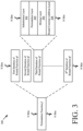
- FIG. 3 there is provided a schematic illustration that is useful for understanding the unique permutation function f of the present solution which is employed in the sponge and duplex constructions described above in relation to FIGS. 1-2 .
- the permutation function f supports any key size (e.g., 128 bits or 256 bits) and is bijective. Since the permutation function f is bijective, f -1 (inverse of f ) exists by definition. While f -1 is not used in practice, it may be helpful for cryptanalysis and verification purposes. Notably, the number of bits that are input and/or output from the permutation function f is also customizable.
- the permutation function f comprises a round function f round that is iterated R times, depending on the key size.
- the round function f round consists of the following layers: a substitution layer 302; a permutation layer 304; a mixing layer 306; and a round constant addition layer 308.
- the substitution layer 302 the bits input thereto are substituted with first substitute bits in accordance with a particular transformation and/or mapping algorithm. For example, input bits 010001 are substituted with bits 1010. The number of bits input/output to/from the substitution layer 302 can be the same or different.
- the permutation layer 304 the bits input thereto are re-arranged.
- the mixing layer 306 at least two outputs of the permutation layer are combined together.
- the round constant addition layer 308 a constant is added to the output of the mixing layer. The manners in which the operations of each layer 302-308 are achieved will be discussed in detail below.
- R is a customizable element of the permutation function f .
- R is determined by (1) calculating the number of rounds needed for linear and differential cryptanalysis and (2) adding some buffer to increase the security margin.
- the substitution layer 302 comprises a plurality of identical substitution boxes (or S-boxes) 402 1 , 402 2 , 402 3 , 402 4 , ..., 402 (N-1)/16 , 402 N/16 which collectively receive N input bits (e.g., 512 input bits) and individually receive X bits of the N input bits (e.g., 16 bits of 512 input bits).
- N is selected to be large enough to keep a cryptographic key secure.
- the value of N is selected to be 512 bits for a cryptographic key having a size of 128 bits or 256 bits.
- a user performs a user-software interaction to select at least one of a plurality of chaotic, random or pseudo-random algorithms that is to be used to generate values for the invertible matrix A and/or the vector b.
- the same or different algorithm can be used to generate numbers for the invertible matrix A and the vector b.
- the user may also enter or select values for parameters of the selected chaotic, random or pseudo-random algorithm(s).
- the present solution is not limited to the particulars of this example.
- bitwise permutation function includes a linear permutation function, an affine permutation function, or a random permutation function.
- bitwise permutation function 404 is customized by changing the permutation formula, but meeting the following criteria.
- Customization can be achieved by either selecting one of a plurality of predefined and/or preprogrammed permutation functions or by allowing a customer to enter their own unique permutation formula.
- the mixing layer 306 comprises a mixing function that is implemented via a plurality of mixers 406 1 , 406 2 , . . ., 410 16 .
- one mixer is provided for every two S-boxes.
- the present solution is not limited in this regard.
- the particular number of S-boxes per mixer is customizable.
- the mixing function is a customizable element of the present solution. The purpose of the mixing function is to provide local diffusion (i.e., across two words) and increase the linear and differential branch numbers of a round from two to three.
- the set of irreducible polynomials (e.g., 256) is selected at the factory from the 4,080 different 16-degree polynomials. Accordingly, a different set of irreducible polynomials (e.g., 256) can be selected for each customer to achieve customization of the cryptographic algorithm, i.e., a new set of predefined irreducible polynomials (e.g., 256) can be from the 4,080 different 16-degree polynomials for each customer.
- the bit string is entered by the user in the field.
- the bit string includes arbitrary bits.
- the user has no expertise with regard to cryptography. Still, the user is able to change the encryption/decryption algorithm without causing any degradation to the security thereof.
- the round constant addition layer 308 comprises a plurality of addition operations represented by blocks 408 1 , 408 2 , 408 3 , 408 4 ,. . ., 408 (N-1)/16 , 408 N/16 .
- the purpose of the addition operations is to add a constant N bit value to the state using bitwise XOR in order to disrupt symmetry and prevent slide attacks.
- the round constant must be fixed random N-bit values.
- Each round i must use a different round constant.
- the round constant is customizable, and should be unique for each round to prevent against slide attacks and be random, pseudorandom or highly asymmetric to reduce symmetry in the state. Accordingly, the round constant addition layer 308 is customizable by simply choosing different round constants, but meeting the following criteria.
- At least one of the following criteria may additionally be met.
- the present algorithm is highly customizable within a security margin. This customizability is useful in cases where different users want unique, proprietary algorithms.
- the following features of the present solution are customizable: (1) the state initialization; (2) the number of rounds R; (3) the permutation function f ; (4) the number of bits N input into the round function; (5) the type, number, parameters and mapping function of the S-boxes; (6) the bitwise permutation function; (7) the mixing function; and (8) the round constants.
- Method 600 begins with step 602 and continues with optional step 604.
- a cryptographic key is concatenated with a flag value.
- the cryptographic key is combined with state initialization bits to generate the first combination bits.
- a multi-bit value for the state initialization bits may be selected such that it is unique for a given application.
- the first combination bits are then used to produce a first keystream, as shown by step 608.
- the first keystream may optionally be truncated to a desired length, as shown by step 610.
- the first keystream is produced using a permutation function f .
- the permutation function f is performed using the first combination bits as inputs thereof.
- the permutation function f comprises a round function f round that is iterated R times.
- the round function f round consists of (1) a substitution layer in which the first combination bits are substituted with substitute bits, (2) a permutation layer in which the substitute bits are re-arranged, (3) a mixing layer in which at least two outputs of the permutation layer are combined together, and (4) an addition layer in which a constant is added to the output of the mixing layer.
- Step 612 involves padding the first data to make a total number of bits contained therein a multiple of the total number of state initialization bits prior to being encrypted.
- the first data is then encrypted using the first keystream, as shown by step 614.
- the first data may be combined with the first keystream using modular arithmetic (e.g., modulo 2 addition).
- the first data comprises, but is not limited to, authentication data and/or message body data.
- Step 618 involves producing a second keystream by performing the permutation function f using the first keystream as inputs thereto.
- Step 620 involves using the second keystream to encrypt the second data so as to produce the second encrypted data (e.g., ciphertext).
- method 600 ends or other processing is performed (e.g., repeat steps 618-620 for a next block of message data), as shown by step 628.
- FIG. 7 is a flow diagram of an illustrative method 700 for customizing a permutation function f .
- the customization changes the permutation function f without degenerating the security of the encryption/decryption algorithm.
- FIG. 7 includes a plurality of blocks 704-712 to illustrate that the permutation function f can be customized in various ways.
- FIG. 7 can be modified to eliminate any of the blocks or to show certain block as optional blocks.
- the present solution is not limited to the order in which the blocks are shown in FIG. 7 .
- block 712 can reside before block 710.
- method begins with 702 and continues with 704 where a first user-software interaction is performed to customize an S-box (e.g., S-box 402 1 , ..., or 402 N/16 of FIG. 4 ) of a substitution layer (e.g., substitution layer 302 of FIG. 3 ).
- S-box e.g., S-box 402 1 , ..., or 402 N/16 of FIG. 4
- substitution layer e.g., substitution layer 302 of FIG. 3
- the customization is achieved by changing a polynomial equation and/or by changing an input-to-output bit mapping, such that the S-box (1) has input values and output values that are all different, (2) does not have an output value that is equal to the corresponding input value, (3) does not have an output value that is a bitwise complement of the corresponding input value, (4) has a maximum differential probability of 2 -14 or smaller, and (5) has a maximum linear bias of 2 -8 or smaller.
- the values may be randomly selected in accordance with a chaotic, random or pseudo-random number algorithm.
- the same or different chaotic, random or pseudo-random number algorithm can be used to specify values for the multi-bit invertible matrix A and the multi-bit vector b.
- the first user-software interaction can be achieved using an input device (e.g., a touch screen 854 of FIG. 8 , a keypad 850 of FIG. 8 , a mouse, a drop down menu or any other input means) provided by a computing device (such as that shown in FIG. 8 ).
- a permutation formula is changed for a bitwise permutation function of a permutation layer (e.g., permutation layer 304 of FIG. 3 ).
- This change can be achieved by performing a second user-software interaction to (a) select a permutation formula from a plurality of predefined permutation formulas, or (b) enter a unique permutation formula that is not included in the plurality of predefined permutation formulas.
- each output bit of a given S-box goes to a different mixer's input bit; (2) bit positions of bits input to the permutation layer are different than the positions of corresponding bits output from the permutation layer; and (3) an order of each bit position is greater than a number of rounds in a bijective function.
- the second user-software interaction can be achieved using a touch screen, a key pad, a mouse, a drop down menu or any other input means provided by a computing device (such as that shown in FIG. 8 ).
- a third user-software interaction is performed to select a set of irreducible polynomial equations from a plurality of polynomial equations.
- the selected set is pre-program for possible use by mixers (e.g., mixers 406 1 ,.., 406 16 of FIG. 4 ) of a mixing layer (e.g., mixing layer 306 of FIG. 3 ).
- mixers e.g., mixers 406 1 ,.., 406 16 of FIG. 4
- a mixing layer e.g., mixing layer 306 of FIG. 3
- each of the plurality of polynomial equations comprises a degree-16 irreducible polynomial equation.
- a fourth user-software interaction is performed in 710 to select, for each mixer of the mixing layer, an irreducible polynomial p(x) from the pre-programmed set of irreducible polynomials.
- This selecting can be achieved by: receiving a first user-software interaction for entering a first bit string comprising a plurality of first arbitrary bits; breaking the first bit string into a plurality of equal length segments each comprising only a portion of the plurality of first bits; and converting/translating each of the equal length segments into irreducible polynomial coefficients into irreducible polynomial coefficients and/or an irreducible polynomial identifier, as described above.
- the computing device 800 comprises a user interface 802, a CPU 806, a system bus 810, a memory 812 connected to and accessible by other portions of computing device 800 through system bus 810, and hardware entities 814 connected to system bus 810.
- the user interface can include input devices (e.g., a keypad 850 ) and output devices (e.g., speaker 852, a display 854, and/or light emitting diodes 856 ), which facilitate user-software interactions for controlling operations of the computing device 800.
- the present solution provides a self-synchronizing mode of operation for the cryptographic systems (such as those described above in relation to FIGS. 1-8 ) employing block cipher based cryptographic algorithms.
- the self-synchronizing mode of operation enables automatic cryptographic resynchronization between transmitters and receivers, and also enables late network entry by communication devices into an already established conversation.
- the self-synchronizing mode of operation provides a way for a receiver to synchronize its local cryptographic algorithm when joining a conversation for which the synchronization information and initialization variable for the cryptographic algorithm has already been sent to participants. Based on pseudo-random events, the communication devices of a participant self-synchronize their cryptographic algorithms during the conversation.
- the pseudo-random events are based on the ciphertext being transmitted because the ciphertext appears statistically random. Every node on the network has access to the ciphertext, and is configured to detect patterns in the ciphertext. When a pattern is detected, a node will re-initialize a state of its cryptographic algorithm using the ciphertext transmitted over the channel.
- the channel may include, but is not limited to, a low bit error rate channel. In this way, the nodes will access uncorrupted ciphertext and concurrently synchronize states of their cryptographic algorithms.
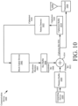
- the communication device 1000 comprises a transmitter circuit employing traditional block cipher encryption.
- the traditional block cipher encryption can include, but is not limited to, Advanced Encryption Standard (AES) based encryption, Data Encryption Standard (DES) based encryption, International Data Encryption Algorithm (IDEA) based encryption, and/or RC5 based encryption.
- AES Advanced Encryption Standard
- DES Data Encryption Standard
- IDEA International Data Encryption Algorithm
- RC5 based encryption
- the pattern detector 1022 obtains ciphertext 1020 from the CT buffer 1018 and analyzes the same to detect a known fixed pattern therein (e.g., 100110101).
- the known fixed pattern is defined by a given number of bits which is equal to or less than the total number of bits in the keystream block(s) 1004.
- the keystream block(s) 1004 include(s) sixty-four bits or one hundred twenty eight bits, while the known fixed pattern includes five to eleven bits. The present solution is not limited in this regard.
- the length of the known fixed pattern defines the statistical frequency at which the pattern will be detected by the pattern detector 1022. The shorter the pattern the more frequently the pattern is detected by the pattern detector 1022. The longer the pattern the less frequently the pattern is detected by the pattern detector 1022.
- the pattern length can be selected by a user of the communication device 902, and specifies an average frequency of cryptographic algorithm re-synchronization. Shorter patterns allow for quicker late network entry by the communication device 902 to an established conversation, but with a reduced performance. Longer patterns allow for an improved performance, but with a slower late network entry by the communication device 902. In response to the user selection of a pattern length, the communication device 902 performs operations to configure the pattern detector 1022 to detect a given pattern from a list of pre-defined known fixed patterns which has the user selected pattern length.
- the ciphertext 1020 of a given iteration of the pattern detection process can include one or more bits of ciphertext, and can have a total number of bits that is equal to or less than the keystream block(s) 1004.
- a keystream block 1004 has N bites (e.g., sixty-four bits or one hundred twenty eight bits), while the ciphertext 1020 analyzed by the pattern detector 1022 comprises N-M bits (e.g., thirty-seven bits).
- M and N are integers.
- the bit size of the ciphertext 1020 can increase by one bit per iteration of the pattern detection process performed by pattern detector 1022.
- the communication device 1100 comprises a receiver circuit employing traditional block cipher decryption.
- the traditional block cipher decryption can include, but is not limited to, AES based decryption, DES based decryption, IDEA based decryption, and/or RC5 based decryption.
- AES based decryption DES based decryption
- IDEA based decryption IDEA based decryption
- RC5 based decryption RC5 based decryption.
- Communication device 1100 receives ciphertext (e.g., ciphertext 1016 of FIG. 10 ) via antenna 1102 and receiver 1104.
- Ciphertext bits 1114 are provided to the combiner 1120 in a bit-by-bit manner.
- the combiner 1120 combines each ciphertext bit 1114 with a keystream bit 1118 to generate a plaintext bit 1122. This combining can be achieved via modulo arithmetic.
- the plaintext bit 1122 is then provided to the computing device 1124.
- the computing device 1124 can store and further process the plaintext bits (e.g., for display or otherwise output to a user thereof).
- the keystream bits 1118 are generated by the block cipher device 1112 and stored in the key buffer 1116.
- the block cipher device 1112 is configured to perform a block cipher decryption algorithm for decrypting ciphertext 1114 received by communication device 1100. This decryption is achieved using bits of keystream block(s) 1114 output from the block cipher device 1112. As described above, the decryption is achieved by combining ciphertext bits with keystream bits the combiner 1120.
- the ciphertext bits 1114 are also provided to the ciphertext buffer 1106 for storage therein.
- Ciphertext 1108 is provided from the ciphertext buffer 1106 to the pattern detector 1120.
- Pattern detector 1120 analyzes the ciphertext 1108 to detect a known fixed pattern therein (e.g., 100110101).
- the known fixed pattern is defined by a given number of bits which is equal to or less than the total number of bits in the keystream block(s) 1114.
- the keystream block(s) 1114 include(s) sixty-four bits or one hundred twenty eight bits, while the known fixed pattern includes five to eleven bits. The present solution is not limited in this regard.
- the length of the known fixed pattern defines the statistical frequency at which the pattern will be detected by the pattern detector 1120.
- the pattern detector 1120 When the pattern is detected, the pattern detector 1120 provides the ciphertext 1108 to the block cipher device 111.
- the block cipher device 1112 uses the ciphertext 1108 as an initialization value to re-initialize a state of the block cipher decryption algorithm.
- FIGS. 12-17 Illustrative communication devices are shown in FIGS. 12-17 which employ duplex constructions and are configured to self-synchronize the same.
- An illustrative duplex sponge construction is described above in relation to FIG. 2 .
- the discussion of FIG. 2 is sufficient for understanding the cryptographic algorithm employed by the communication devices of FIGS. 12-14 .
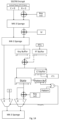
- FIG. 12 there is provided an illustration of an illustrative transmitting communication device 1200 configured to operate in a self-synchronization mode for synchronizing and re-synchronizing its sponge based cryptographic algorithm.
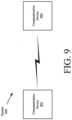
- the communication device 1200 may comprise communication device 902 of FIG. 9 .
- the sponge based cryptographic algorithm implements a permutation function f described above in relation to FIGS. 3-5 .
- the communication device 1200 comprises combiners 1202, 1206, 1209 and permutation functional blocks 1204, 1208, 1234.
- These listed components 1202, 1204, 1206, 1208, 1209, 1234 are the same as or similar to components 226, 208, 228, 210, 230, 212 of FIG. 2 .
- the discussion of components 226, 208, 228, 210, 230, 212 of FIG. 2 is sufficient for understanding components 1202, 1204, 1206, 1208, 1209, 1234 of FIG. 12 .
- the synchronization circuit 1250 comprises a key buffer 1210, a combiner 1218, a PT buffer 1212, a CT buffer 1222, a pattern detector 1226, and multiplexers (or other switching/selection devices) 1230, 1232.
- the synchronization circuit 1250 is coupled to a computing device 1248.
- Computing device 1248 can be the same as or similar to computing device 800 of FIG. 8 .
- One or more components of the synchronization circuit 1250 can be implemented by or integrated with computing device 1030. Accordingly, the listed components comprise hardware, software and/or machine-readable media.
- the synchronization circuit 1250 receives message body data B from the computing device 1248 and a keystream block Z 1 from permutation functional block 1208.
- the message body data B is stored in PT buffer 1212
- the keystream block Z 1 is stored in key buffer 1210.
- a single bit 1216 of plaintext is provided from the PT buffer 1212 to the combiner 1218.
- a single bit 1214 of a keystream block is provided from the key buffer 1210 to the combiner 1218.
- the combiner 12184 combines the plaintext bit 1216 with the keystream bit 1214 to generate a ciphertext bit 1220. This combining can be achieved via modulo arithmetic.
- the ciphertext bit 1220 is stored in the CT buffer 1222 and transmitted from the communication device 1200 via a transceiver 1236 and an antenna 1238. Transceivers and antennas are well known.
- the length of the known fixed pattern defines the statistical frequency at which the pattern will be detected by the pattern detector 1226. The shorter the pattern the more frequently the pattern is detected by the pattern detector 1226. The longer the pattern the less frequently the pattern is detected by the pattern detector 1226.
- the pattern length can be selected by a user of the communication device 1200, and specifies an average frequency of cryptographic algorithm re-synchronization. Shorter patterns allow for quicker late network entry by the communication device 1200 to an established conversation, but with a reduced performance. Longer patterns allow for an improved performance, but with a slower late network entry by the communication device 1200. In response to the user selection of a pattern length, the communication device 1200 performs operations to configure the pattern detector 1226 to detect a given pattern from a list of pre-defined known fixed patterns which has the user selected pattern length.
- the pattern detector 1226 When the pattern is detected, the pattern detector 1226 generates and provides a resynchronization signal 1228 to multiplexers 1230, 1232.
- the resynchronization signal 1228 causes the ciphertext 1224 to be passed to the permutation functional block 1234 instead of the keystream block Z 1 , and causes a value of zero to be passed to the permutation functional block 1234 instead of the capacity c 1 .
- the permutation functional block 1234 uses the ciphertext 1224 and zero value to re-initialize the cryptographic algorithm. More specifically, the unique permutation function f is performed in the permutation functional block 1234 using the ciphertext 1224 and zero value as inputs to generate a keystream block Z 2 .
- the keystream block Z 1 and capacity c 1 are passed to the permutation functional block 1234 when the pattern is not detected by the pattern detector 1226 and the resynchronization signal 1228 is not being provided to the multiplexers 1230, 1232.
- the permutation function f is performed in the permutation functional block 1234 using the keystream block Z 1 and capacity c 1 as inputs to generate a keystream block Z 2 .
- the keystream block(s) can be truncated in manner described above in relation to FIG. 2 .
- An illustration showing a modified version of the duplex construction 200 is provided in FIG. 13 .
- the modified duplex construction 200' includes the synchronization circuit 1250 of FIG. 12 inserted between permutation functional blocks 210 and 212.
- the duplex construction employed by communication device can comprise an MK-3 cryptographic algorithm.
- An illustration showing implementation of the present solution in an MK-3 context is provided in FIG. 14 .
- the MK-3 cryptographic algorithm first absorbs the key into the algorithm state.
- the Initialization Variable (IV) is absorbed into the algorithm state.
- the MK-3 cryptographic algorithm is ready to process data.
- the Rate (R) portion of algorithm state is loaded into the key buffer and plaintext is loaded into the plaintext buffer.
- the contents of the key and plaintext buffers are left shifted by one bit at a time, mod-2 added together and left shifted into the ciphertext buffer. Encryption continues in this manner until another iteration is initiated.
- Another iteration will begin either when the entire block of keystream is consumed or when the pattern detector is triggered. If another iteration is triggered when a block of keystream is consumed, the ciphertext buffer contents are concatenated with the capacity portion of the algorithm state and passed on for the next iteration of processing by the MK-3 cryptographic algorithm. If another iteration is triggered by the pattern detector, the traffic key is re-absorbed by mod-2 adding it into the ciphertext buffer. The ciphertext buffer contents are concatenated with a vector of all zeros and are passed on for the next iteration of processing by the MK-3 cryptographic algorithm.
- FIG. 15 there is provided an illustration of a receiving communication device 1500 that is configured to operate in a self-synchronization mode for synchronizing and re-synchronizing its sponge based cryptographic algorithm.
- the communication device 1500 can be comprise communication device 904 of FIG. 9 .
- the sponge based cryptographic algorithm implements a permutation function f described above in relation to FIGS. 3-5 .
- the communication device 1500 comprises combiners 1520, 1524, 1515 and permutation functional blocks 1522, 1526, 1528.
- These listed components 1515, 1520-1528 are the same as or similar to components 226, 208, 228, 210, 230, 212 of FIG. 2 .
- the discussion of components 226, 208, 228, 210, 230, 212 of FIG. 2 is sufficient for understanding components 1515, 1520-1528 of FIG. 15 .
- Communication device 1500 also comprises a synchronization circuit 1550.
- the synchronization circuit 1550 is configured to facilitate a self-synchronizing mode of operation.
- the self-synchronizing mode of operation enables automatic cryptographic resynchronization between communication device 1500 and another communication device (e.g., communication device 902 of FIG. 9 ).
- the communication device 1500 self-synchronizes it's cryptographic algorithm during on-going conversations or communication sessions.
- the pseudo-random events are based on the ciphertext being transmitted from the communication device 1500 because the ciphertext appears statistically random.
- the synchronization circuit 1550 is configured to detect patterns in the ciphertext. When a pattern is detected, the synchronization circuit 1550 will cause a state of the cryptographic algorithm to be re-initialized using the ciphertext as an initialization value.
- the communication device 1500 receives ciphertext via antenna 1502 and receiver 1504.
- the ciphertext 1506 is passed to the synchronization circuit 1550.
- the ciphertext 1506 is stored in the CT buffer 1508, and provided to the combiner 1534 in a bit-by-bit manner.
- the combiner 1534 combines each ciphertext bit 1506 with a keystream bit 1532 to generate a plaintext bit 1536. This combining can be achieved via modulo arithmetic.
- the plainttext bit 1536 is then provided to the ' computing device 1540.
- the computing device 1540 can store and further process the plainttext bits (e.g., for display or otherwise output to a user thereof).
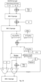
- the keystream bits 1532 are generated by the cryptographic algorithm and stored in the key buffer 1530.
- the cryptographic algorithm is configured to perform a sponge based decryption algorithm for decrypting ciphertext 1506 received by communication device 1500. This decryption is achieved using bits of keystream block(s) Z 1 output from the cryptographic device. As described above, the decryption is achieved by combining ciphertext bits with keystream bits the combiner 1534.
- the ciphertext 1510 is provided from the ciphertext buffer 1508 to the pattern detector 1512.
- Pattern detector 1512 analyzes the ciphertext 1510 to detect a known fixed pattern therein (e.g., 100110101).
- the known fixed pattern is defined by a given number of bits which is equal to or less than the total number of bits in the keystream block(s) Z 1 .
- the keystream block(s) Z 1 include(s) sixty-four bits or one hundred twenty eight bits, while the known fixed pattern includes five to eleven bits.
- the present solution is not limited in this regard.
- the length of the known fixed pattern defines the statistical frequency at which the pattern will be detected by the pattern detector 1512.
- the pattern detector 1512 When the pattern is detected, the pattern detector 1512 generates and provides a resynchronization signal 1514 to multiplexers 1516, 1518.
- the resynchronization signal 1514 causes the ciphertext 1510 to be passed to the permutation functional block 1528 instead of the keystream block Z 1 , and causes a value of zero to be passed to the permutation functional block 1528 instead of the capacity c 1 .
- the permutation functional block 1528 uses the ciphertext 1510 and zero value to re-initialize the cryptographic algorithm. More specifically, the unique permutation function f is performed in the permutation functional block 1528 using the ciphertext 1510 and zero value as inputs to generate a keystream block Z 2 .
- the keystream block Z 1 and capacity c 1 are passed to the permutation functional block 1528 when the pattern is not detected by the pattern detector 1512 and the resynchronization signal 1514 is not being provided to the multiplexers 1516, 1518.
- the permutation function f is performed in the permutation functional block 1528 using the keystream block Z 1 and capacity c 1 as inputs to generate a keystream block Z 2 .
- FIG. 16 there is provided an illustration of a receiving communication device implementing an MK-3 cryptographic algorithm and configured to synchronize/re-synchronize the same in accordance with the present solution.
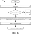
- Method 1700 begins with 1702 and continues to 1704 where ciphertext is obtained.
- 1704 can involve generating the ciphertext by a cryptographic system in accordance with a cryptographic algorithm or receiving the ciphertext from a remote device.
- the cryptographic algorithm can include, but is not limited to, an adaption of a sponge construction framework.
- the adaptation of the sponge construction framework can include, but is not limited to, a duplex construction in which a permutation function is iteratively performed (e.g., as shown in FIG. 2 ).
- This detection can be made based on an analysis of the ciphertext. For example, the system can analyze the ciphertext to determine whether a given sequence of values exits within the ciphertext. If the given sequence of values does exist within the ciphertext so, then the pseudo-random event is deemed to exist.
- method 1700 continues with 1712 which will be discussed below. In contrast, when the pseudo-random event does exit, then method 1700 continues with 1710-1712.
- 1710 involves synchronizing the cryptographic system with another cryptographic system using the ciphertext as at least part of an initialization value for the cryptographic algorithm.
- the ciphertext is used in 1710 as a bitrate portion r of the initialization value, while zero is used as a capacity portion c of the initialization value for the cryptographic algorithm.
- the cryptographic algorithm is performed to encrypt or decrypt information.
- results from combining plaintext with a keystream block is used in 1712 as the bitrate portion of the initialization value for a cryptographic algorithm when the pseudo-random event was not detected in 1706 (and/or a determination is made that a given sequence of values does not exist within the ciphertext).
- 1714 is performed where method 1700 ends or other operations are performed (e.g., return to 1702 ).
Landscapes
- Engineering & Computer Science (AREA)
- Computer Security & Cryptography (AREA)
- Computer Networks & Wireless Communication (AREA)
- Signal Processing (AREA)
- Mobile Radio Communication Systems (AREA)
Claims (7)
- Ein Verfahren zum Betreiben eines kryptographischen Systems, umfassend:Erlangung des Geheimtextes durch das kryptographische System;Durchführen von Operationen durch das kryptographische System, um zu bestimmen, ob eine gegebene Folge von Werten innerhalb des verschlüsselten Textes existiert, wobei die Länge der Folge von Werten von einem Benutzer ausgewählt werden kann; undSynchronisieren des kryptographischen Systems mit einem anderen kryptographischen System unter Verwendung des Chiffriertextes als einen Bitratenanteil R eines Initialisierungswertes B für einen kryptographischen Algorithmus und Null als einen Kapazitätsanteil C des Initialisierungswertes für den kryptographischen Algorithmus, indem veranlasst wird, dass ein Zustand des kryptographischen Algorithmus unter Verwendung des Chiffriertextes als Initialisierungswert neu initialisiert wird, wenn festgestellt wird, dass die gegebene Folge von Werten innerhalb des Chiffriertextes existiert, wobei B=R+C;dadurch gekennzeichnet, dass der kryptographische Algorithmus eine Anpassung eines Schwamm-Konstruktionsrahmens umfasst und die Anpassung des Schwamm-Konstruktionsrahmens eine Duplex-Konstruktion umfasst, in der eine Permutationsfunktion iterativ ausgeführt wird, wobei der kryptographische Algorithmus eine eindeutige Permutationsfunktion f umfasst, die mit einer Schwamm-Konstruktion und/oder der Duplex-Konstruktion verwendet wird.
- Das Verfahren nach Anspruch 1, das ferner die Verwendung von Ergebnissen aus der Kombination des Klartextes mit einem Schlüsselstromblock als Bitratenanteil des Initialisierungswertes für einen kryptographischen Algorithmus umfasst, wenn festgestellt wird, dass die gegebene Folge von Werten im verschlüsselten Text nicht existiert.
- Das Verfahren nach Anspruch 1, wobei das kryptografische System eine erste benutzerdefinierte Kryptofähigkeitseinstellung umfasst, die beim Einschalten in einem Verschlüsselungs-/Entschlüsselungsschaltkreis gespeichert und geladen und in einer Substitutionsschicht, einer Permutationsschicht und/oder einer Schicht für die Addition von Rundungskonstanten der eindeutigen Permutationsfunktion f implementiert wird.
- Das Verfahren nach Anspruch 3, wobei das kryptografische System ferner eine zweite kundenspezifische Algorithmusmodifizierungsfähigkeit umfasst, die eine kundenspezifische Anpassung des Verschlüsselungs-/Entschlüsselungsalgorithmus nach dem Einschalten ermöglicht und in einem N-Bit-Register gespeichert ist, wobei alle möglichen CAM-Registerwerte unterschiedliche, vollständig sichere kundenspezifische Algorithmen ergeben müssen und in einer Mischerschicht der eindeutigen Permutationsfunktion f implementiert sind.
- Das Verfahren nach Anspruch 1, wobei der Chiffretext von dem kryptographischen System gemäß dem kryptographischen Algorithmus erzeugt oder von einem entfernten Gerät, das den Chiffretext erzeugt hat, empfangen wird.
- Das Verfahren nach Anspruch 1, das ferner die Verwendung des synchronisierten kryptographischen Algorithmus zur Entschlüsselung des Chiffriertextes oder zur Verschlüsselung des Klartextes umfasst.
- Eine Kommunikationsvorrichtung (902), umfassend:einen Sender-Empfänger (1026), der so konfiguriert ist, dass er Signale einschließlich Chiffretext sendet und empfängt;eine Blockchiffriervorrichtung (1002), die so konfiguriert ist, dass sie Informationen gemäß einem kryptografischen Algorithmus verschlüsselt und entschlüsselt; undeine Synchronisationsschaltung (1250), die so konfiguriert ist, dass sie den kryptographischen Algorithmus mit einem kryptographischen Algorithmus einer anderen Kommunikationsvorrichtung (1200) auf der Grundlage einer Erfassung eines Pseudozufallsereignisses während einer laufenden Kommunikationssitzung synchronisiert;wobei das Pseudozufallsereignis über eine Analyse des Chiffriertextes erfasst wird; wobei die Synchronisationsschaltung ferner so konfiguriert ist, dass sie eine gegebene Sequenz von Werten in dem Chiffriertext erfasst, wobei die Länge der Sequenz von Werten von einem Benutzer ausgewählt werden kann; und wenn die Sequenz erfasst wird, die Synchronisationsschaltung ferner so angepasst ist, dass sie veranlasst, dass ein Zustand des kryptographischen Algorithmus unter Verwendung des Chiffriertextes als ein initialisierter Wert reinitialisiert wird; undwobei der Chiffretext als ein Bitratenanteil R des Initialisierungswertes B für den kryptographischen Algorithmus verwendet wird und Null als ein Kapazitätsanteil C des Initialisierungswertes für den kryptographischen Algorithmus verwendet wird, wenn das Pseudozufallsereignis erkannt wird, wobei B=R+C;dadurch gekennzeichnet, dass der kryptographische Algorithmus eine Anpassung eines Schwamm-Konstruktionsrahmens umfasst und die Anpassung des Schwamm-Konstruktionsrahmens eine Duplex-Konstruktion umfasst, in der eine Permutationsfunktion iterativ ausgeführt wird, wobei der kryptographische Algorithmus eine eindeutige Permutationsfunktion f umfasst, die mit einer Schwamm-Konstruktion und/oder der Duplex-Konstruktion verwendet wird.
Applications Claiming Priority (1)
| Application Number | Priority Date | Filing Date | Title |
|---|---|---|---|
| US17/229,608 US11870884B2 (en) | 2021-04-13 | 2021-04-13 | Self-synchronizing mode of operation for an encryption/decryption algorithm |
Publications (2)
| Publication Number | Publication Date |
|---|---|
| EP4075718A1 EP4075718A1 (de) | 2022-10-19 |
| EP4075718B1 true EP4075718B1 (de) | 2024-12-18 |
Family
ID=81325692
Family Applications (1)
| Application Number | Title | Priority Date | Filing Date |
|---|---|---|---|
| EP22166111.9A Active EP4075718B1 (de) | 2021-04-13 | 2022-03-31 | Selbstsynchronisierungsmodus für einen verschlüsselungs- und entschlüsselungsalgorithmus |
Country Status (2)
| Country | Link |
|---|---|
| US (1) | US11870884B2 (de) |
| EP (1) | EP4075718B1 (de) |
Families Citing this family (3)
| Publication number | Priority date | Publication date | Assignee | Title |
|---|---|---|---|---|
| US12407500B2 (en) * | 2021-11-29 | 2025-09-02 | T-Mobile Usa, Inc. | Quantum cryptographic keys for secure wireless communications in a telecommunications network |
| US12413386B2 (en) * | 2022-12-20 | 2025-09-09 | New Keys Lab Ltd. | Chaotic-based encryption |
| US20260088974A1 (en) * | 2024-09-25 | 2026-03-26 | Infineon Technologies Ag | Encrypted communications using a short pulse width modulation (pwm) code (spc) protocol |
Family Cites Families (7)
| Publication number | Priority date | Publication date | Assignee | Title |
|---|---|---|---|---|
| US6108421A (en) | 1998-03-06 | 2000-08-22 | Harris Corporation | Method and apparatus for data encryption |
| US7599490B2 (en) | 2004-03-03 | 2009-10-06 | Harris Corporation | Method and apparatus for data encryption |
| US8515059B2 (en) * | 2010-03-30 | 2013-08-20 | Daniel W. Engels | Cryptographic processor with dynamic update of encryption state |
| ES2409458B1 (es) | 2011-04-12 | 2014-06-24 | Telef�Nica, S.A. | Método y sistema para mejorar la sincronización de cifrados de flujo |
| US9596075B2 (en) * | 2014-06-03 | 2017-03-14 | L3 Technologies, Inc. | Transparent serial encryption |
| US9438416B2 (en) | 2014-07-18 | 2016-09-06 | Harris Corporation | Customizable encryption algorithm based on a sponge construction with authenticated and non-authenticated modes of operation |
| US10666437B2 (en) * | 2017-11-07 | 2020-05-26 | Harris Solutions NY, Inc. | Customizable encryption/decryption algorithm |
-
2021
- 2021-04-13 US US17/229,608 patent/US11870884B2/en active Active
-
2022
- 2022-03-31 EP EP22166111.9A patent/EP4075718B1/de active Active
Also Published As
| Publication number | Publication date |
|---|---|
| US11870884B2 (en) | 2024-01-09 |
| US20220337394A1 (en) | 2022-10-20 |
| EP4075718A1 (de) | 2022-10-19 |
Similar Documents
| Publication | Publication Date | Title |
|---|---|---|
| Aoki et al. | Camellia: A 128-bit block cipher suitable for multiple platforms—design andanalysis | |
| EP3480999B1 (de) | Anpassbarer verschlüsselung-/entschlüsselungsalgorithmus | |
| EP4075718A1 (de) | Selbstsynchronisierungsmodus für einen verschlüsselungs- und entschlüsselungsalgorithmus | |
| US8660265B2 (en) | Cipher implementation | |
| EP1246389B1 (de) | Vorrichtung zur wählbaren Ver- bzw. Entschlüsselung von Daten | |
| US9438416B2 (en) | Customizable encryption algorithm based on a sponge construction with authenticated and non-authenticated modes of operation | |
| US20170195116A1 (en) | Method and apparatus for efficiently implementing the advanced encryption standard | |
| Mohurle et al. | Review on realization of AES encryption and decryption with power and area optimization | |
| US20040202318A1 (en) | Apparatus for supporting advanced encryption standard encryption and decryption | |
| Sivakumar et al. | High speed VLSI design CCMP AES cipher for WLAN (IEEE 802.11 i) | |
| Emon et al. | Advanced Encryption Standard for embedded applications: An FPGA-based implementation using VHDL | |
| Abdulazeez et al. | Design and Implementation of Advanced Encryption Standard Security Algorithm using FPGA | |
| Salameh | A new symmetric-key block ciphering algorithm | |
| Sugawara et al. | ASIC performance comparison for the ISO standard block ciphers | |
| US12627468B2 (en) | Systems and methods for providing substitution boxes | |
| Lanjewar et al. | Implementation of aes-256 bit: A review | |
| Guzmán et al. | FPGA implementation of the AES-128 algorithm in non-feedback modes of operation | |
| Dulla et al. | A unique message encryption technique based on enhanced blowfish algorithm | |
| Aoki et al. | The 128-bit block cipher Camellia | |
| Mahmoud et al. | Improved Rijndael Algorithm by Encryption S-Box Using NTRU Algorithm | |
| Kitsos | Hardware implementations for the ISO/IEC 18033-4: 2005 standard for stream ciphers | |
| Nayana et al. | VLSI implementation of AES Encryption/Decryption Algorithm using FPGA | |
| Rohiem et al. | FPGA implementation of reconfigurable parameters AES algorithm | |
| Varhade et al. | A Review on Implementation of AES Algorithm Using FPGA & Its Performance Analysis | |
| Sklavos et al. | Reconfigurable crypto processor design of encryption algorithms operation modes methods and FPGA integration |
Legal Events
| Date | Code | Title | Description |
|---|---|---|---|
| PUAI | Public reference made under article 153(3) epc to a published international application that has entered the european phase |
Free format text: ORIGINAL CODE: 0009012 |
|
| STAA | Information on the status of an ep patent application or granted ep patent |
Free format text: STATUS: REQUEST FOR EXAMINATION WAS MADE |
|
| 17P | Request for examination filed |
Effective date: 20220331 |
|
| AK | Designated contracting states |
Kind code of ref document: A1 Designated state(s): AL AT BE BG CH CY CZ DE DK EE ES FI FR GB GR HR HU IE IS IT LI LT LU LV MC MK MT NL NO PL PT RO RS SE SI SK SM TR |
|
| GRAP | Despatch of communication of intention to grant a patent |
Free format text: ORIGINAL CODE: EPIDOSNIGR1 |
|
| STAA | Information on the status of an ep patent application or granted ep patent |
Free format text: STATUS: GRANT OF PATENT IS INTENDED |
|
| RIC1 | Information provided on ipc code assigned before grant |
Ipc: H04L 9/12 20060101ALI20240904BHEP Ipc: H04L 9/06 20060101AFI20240904BHEP |
|
| INTG | Intention to grant announced |
Effective date: 20240917 |
|
| GRAS | Grant fee paid |
Free format text: ORIGINAL CODE: EPIDOSNIGR3 |
|
| GRAA | (expected) grant |
Free format text: ORIGINAL CODE: 0009210 |
|
| STAA | Information on the status of an ep patent application or granted ep patent |
Free format text: STATUS: THE PATENT HAS BEEN GRANTED |
|
| P01 | Opt-out of the competence of the unified patent court (upc) registered |
Free format text: CASE NUMBER: APP_60115/2024 Effective date: 20241107 |
|
| AK | Designated contracting states |
Kind code of ref document: B1 Designated state(s): AL AT BE BG CH CY CZ DE DK EE ES FI FR GB GR HR HU IE IS IT LI LT LU LV MC MK MT NL NO PL PT RO RS SE SI SK SM TR |
|
| REG | Reference to a national code |
Ref country code: CH Ref legal event code: EP |
|
| REG | Reference to a national code |
Ref country code: DE Ref legal event code: R096 Ref document number: 602022008726 Country of ref document: DE |
|
| REG | Reference to a national code |
Ref country code: IE Ref legal event code: FG4D |
|
| REG | Reference to a national code |
Ref country code: LT Ref legal event code: MG9D |
|
| PG25 | Lapsed in a contracting state [announced via postgrant information from national office to epo] |
Ref country code: HR Free format text: LAPSE BECAUSE OF FAILURE TO SUBMIT A TRANSLATION OF THE DESCRIPTION OR TO PAY THE FEE WITHIN THE PRESCRIBED TIME-LIMIT Effective date: 20241218 |
|
| PG25 | Lapsed in a contracting state [announced via postgrant information from national office to epo] |
Ref country code: FI Free format text: LAPSE BECAUSE OF FAILURE TO SUBMIT A TRANSLATION OF THE DESCRIPTION OR TO PAY THE FEE WITHIN THE PRESCRIBED TIME-LIMIT Effective date: 20241218 |
|
| PG25 | Lapsed in a contracting state [announced via postgrant information from national office to epo] |
Ref country code: BG Free format text: LAPSE BECAUSE OF FAILURE TO SUBMIT A TRANSLATION OF THE DESCRIPTION OR TO PAY THE FEE WITHIN THE PRESCRIBED TIME-LIMIT Effective date: 20241218 |
|
| PG25 | Lapsed in a contracting state [announced via postgrant information from national office to epo] |
Ref country code: NO Free format text: LAPSE BECAUSE OF FAILURE TO SUBMIT A TRANSLATION OF THE DESCRIPTION OR TO PAY THE FEE WITHIN THE PRESCRIBED TIME-LIMIT Effective date: 20250318 |
|
| REG | Reference to a national code |
Ref country code: NL Ref legal event code: MP Effective date: 20241218 |
|
| PG25 | Lapsed in a contracting state [announced via postgrant information from national office to epo] |
Ref country code: GR Free format text: LAPSE BECAUSE OF FAILURE TO SUBMIT A TRANSLATION OF THE DESCRIPTION OR TO PAY THE FEE WITHIN THE PRESCRIBED TIME-LIMIT Effective date: 20250319 Ref country code: LV Free format text: LAPSE BECAUSE OF FAILURE TO SUBMIT A TRANSLATION OF THE DESCRIPTION OR TO PAY THE FEE WITHIN THE PRESCRIBED TIME-LIMIT Effective date: 20241218 |
|
| PG25 | Lapsed in a contracting state [announced via postgrant information from national office to epo] |
Ref country code: RS Free format text: LAPSE BECAUSE OF FAILURE TO SUBMIT A TRANSLATION OF THE DESCRIPTION OR TO PAY THE FEE WITHIN THE PRESCRIBED TIME-LIMIT Effective date: 20250318 |
|
| PG25 | Lapsed in a contracting state [announced via postgrant information from national office to epo] |
Ref country code: NL Free format text: LAPSE BECAUSE OF FAILURE TO SUBMIT A TRANSLATION OF THE DESCRIPTION OR TO PAY THE FEE WITHIN THE PRESCRIBED TIME-LIMIT Effective date: 20241218 |
|
| REG | Reference to a national code |
Ref country code: AT Ref legal event code: MK05 Ref document number: 1753131 Country of ref document: AT Kind code of ref document: T Effective date: 20241218 |
|
| PG25 | Lapsed in a contracting state [announced via postgrant information from national office to epo] |
Ref country code: SM Free format text: LAPSE BECAUSE OF FAILURE TO SUBMIT A TRANSLATION OF THE DESCRIPTION OR TO PAY THE FEE WITHIN THE PRESCRIBED TIME-LIMIT Effective date: 20241218 |
|
| PG25 | Lapsed in a contracting state [announced via postgrant information from national office to epo] |
Ref country code: PL Free format text: LAPSE BECAUSE OF FAILURE TO SUBMIT A TRANSLATION OF THE DESCRIPTION OR TO PAY THE FEE WITHIN THE PRESCRIBED TIME-LIMIT Effective date: 20241218 |
|
| PG25 | Lapsed in a contracting state [announced via postgrant information from national office to epo] |
Ref country code: ES Free format text: LAPSE BECAUSE OF FAILURE TO SUBMIT A TRANSLATION OF THE DESCRIPTION OR TO PAY THE FEE WITHIN THE PRESCRIBED TIME-LIMIT Effective date: 20241218 |
|
| PG25 | Lapsed in a contracting state [announced via postgrant information from national office to epo] |
Ref country code: IS Free format text: LAPSE BECAUSE OF FAILURE TO SUBMIT A TRANSLATION OF THE DESCRIPTION OR TO PAY THE FEE WITHIN THE PRESCRIBED TIME-LIMIT Effective date: 20250418 |
|
| PG25 | Lapsed in a contracting state [announced via postgrant information from national office to epo] |
Ref country code: PT Free format text: LAPSE BECAUSE OF FAILURE TO SUBMIT A TRANSLATION OF THE DESCRIPTION OR TO PAY THE FEE WITHIN THE PRESCRIBED TIME-LIMIT Effective date: 20250421 |
|
| PG25 | Lapsed in a contracting state [announced via postgrant information from national office to epo] |
Ref country code: EE Free format text: LAPSE BECAUSE OF FAILURE TO SUBMIT A TRANSLATION OF THE DESCRIPTION OR TO PAY THE FEE WITHIN THE PRESCRIBED TIME-LIMIT Effective date: 20241218 |
|
| PG25 | Lapsed in a contracting state [announced via postgrant information from national office to epo] |
Ref country code: AT Free format text: LAPSE BECAUSE OF FAILURE TO SUBMIT A TRANSLATION OF THE DESCRIPTION OR TO PAY THE FEE WITHIN THE PRESCRIBED TIME-LIMIT Effective date: 20241218 Ref country code: RO Free format text: LAPSE BECAUSE OF FAILURE TO SUBMIT A TRANSLATION OF THE DESCRIPTION OR TO PAY THE FEE WITHIN THE PRESCRIBED TIME-LIMIT Effective date: 20241218 |
|
| PG25 | Lapsed in a contracting state [announced via postgrant information from national office to epo] |
Ref country code: SK Free format text: LAPSE BECAUSE OF FAILURE TO SUBMIT A TRANSLATION OF THE DESCRIPTION OR TO PAY THE FEE WITHIN THE PRESCRIBED TIME-LIMIT Effective date: 20241218 |
|
| PG25 | Lapsed in a contracting state [announced via postgrant information from national office to epo] |
Ref country code: CZ Free format text: LAPSE BECAUSE OF FAILURE TO SUBMIT A TRANSLATION OF THE DESCRIPTION OR TO PAY THE FEE WITHIN THE PRESCRIBED TIME-LIMIT Effective date: 20241218 |
|
| PG25 | Lapsed in a contracting state [announced via postgrant information from national office to epo] |
Ref country code: SE Free format text: LAPSE BECAUSE OF FAILURE TO SUBMIT A TRANSLATION OF THE DESCRIPTION OR TO PAY THE FEE WITHIN THE PRESCRIBED TIME-LIMIT Effective date: 20241218 |
|
| REG | Reference to a national code |
Ref country code: DE Ref legal event code: R097 Ref document number: 602022008726 Country of ref document: DE |
|
| PG25 | Lapsed in a contracting state [announced via postgrant information from national office to epo] |
Ref country code: DK Free format text: LAPSE BECAUSE OF FAILURE TO SUBMIT A TRANSLATION OF THE DESCRIPTION OR TO PAY THE FEE WITHIN THE PRESCRIBED TIME-LIMIT Effective date: 20241218 |
|
| PG25 | Lapsed in a contracting state [announced via postgrant information from national office to epo] |
Ref country code: MC Free format text: LAPSE BECAUSE OF FAILURE TO SUBMIT A TRANSLATION OF THE DESCRIPTION OR TO PAY THE FEE WITHIN THE PRESCRIBED TIME-LIMIT Effective date: 20241218 |
|
| PLBE | No opposition filed within time limit |
Free format text: ORIGINAL CODE: 0009261 |
|
| REG | Reference to a national code |
Ref country code: CH Ref legal event code: H13 Free format text: ST27 STATUS EVENT CODE: U-0-0-H10-H13 (AS PROVIDED BY THE NATIONAL OFFICE) Effective date: 20251023 |
|
| STAA | Information on the status of an ep patent application or granted ep patent |
Free format text: STATUS: NO OPPOSITION FILED WITHIN TIME LIMIT |
|
| PG25 | Lapsed in a contracting state [announced via postgrant information from national office to epo] |
Ref country code: LU Free format text: LAPSE BECAUSE OF NON-PAYMENT OF DUE FEES Effective date: 20250331 |
|
| 26N | No opposition filed |
Effective date: 20250919 |
|
| REG | Reference to a national code |
Ref country code: BE Ref legal event code: MM Effective date: 20250331 |
|
| PG25 | Lapsed in a contracting state [announced via postgrant information from national office to epo] |
Ref country code: BE Free format text: LAPSE BECAUSE OF NON-PAYMENT OF DUE FEES Effective date: 20250331 |
|
| PG25 | Lapsed in a contracting state [announced via postgrant information from national office to epo] |
Ref country code: CH Free format text: LAPSE BECAUSE OF NON-PAYMENT OF DUE FEES Effective date: 20250331 |
|
| PG25 | Lapsed in a contracting state [announced via postgrant information from national office to epo] |
Ref country code: IE Free format text: LAPSE BECAUSE OF NON-PAYMENT OF DUE FEES Effective date: 20250331 |
|
| PGFP | Annual fee paid to national office [announced via postgrant information from national office to epo] |
Ref country code: GB Payment date: 20260327 Year of fee payment: 5 |
|
| PGFP | Annual fee paid to national office [announced via postgrant information from national office to epo] |
Ref country code: DE Payment date: 20260327 Year of fee payment: 5 |
|
| PGFP | Annual fee paid to national office [announced via postgrant information from national office to epo] |
Ref country code: IT Payment date: 20260319 Year of fee payment: 5 |
|
| PGFP | Annual fee paid to national office [announced via postgrant information from national office to epo] |
Ref country code: FR Payment date: 20260325 Year of fee payment: 5 |