EP4075708A1 - Communication method and communication apparatus - Google Patents
Communication method and communication apparatus Download PDFInfo
- Publication number
- EP4075708A1 EP4075708A1 EP22161250.0A EP22161250A EP4075708A1 EP 4075708 A1 EP4075708 A1 EP 4075708A1 EP 22161250 A EP22161250 A EP 22161250A EP 4075708 A1 EP4075708 A1 EP 4075708A1
- Authority
- EP
- European Patent Office
- Prior art keywords
- reg
- regs
- reg bundle
- cce
- time domain
- Prior art date
- Legal status (The legal status is an assumption and is not a legal conclusion. Google has not performed a legal analysis and makes no representation as to the accuracy of the status listed.)
- Granted
Links
- 238000000034 method Methods 0.000 title claims abstract description 123
- 238000004891 communication Methods 0.000 title claims abstract description 59
- 230000011664 signaling Effects 0.000 claims description 19
- 230000001965 increasing effect Effects 0.000 claims description 15
- 238000004590 computer program Methods 0.000 claims description 14
- 238000012545 processing Methods 0.000 description 43
- 230000015654 memory Effects 0.000 description 40
- 238000010586 diagram Methods 0.000 description 36
- 238000013507 mapping Methods 0.000 description 32
- 230000006870 function Effects 0.000 description 26
- 238000013461 design Methods 0.000 description 21
- 238000003860 storage Methods 0.000 description 21
- 239000011159 matrix material Substances 0.000 description 17
- 230000008569 process Effects 0.000 description 13
- 101150071746 Pbsn gene Proteins 0.000 description 7
- 230000003247 decreasing effect Effects 0.000 description 6
- 230000002776 aggregation Effects 0.000 description 5
- 238000004220 aggregation Methods 0.000 description 5
- 230000005540 biological transmission Effects 0.000 description 5
- 238000010295 mobile communication Methods 0.000 description 5
- 238000000794 confocal Raman spectroscopy Methods 0.000 description 4
- 238000011500 cytoreductive surgery Methods 0.000 description 4
- 108010076504 Protein Sorting Signals Proteins 0.000 description 3
- 239000007787 solid Substances 0.000 description 3
- 101000741965 Homo sapiens Inactive tyrosine-protein kinase PRAG1 Proteins 0.000 description 2
- 102100038659 Inactive tyrosine-protein kinase PRAG1 Human genes 0.000 description 2
- 230000009471 action Effects 0.000 description 2
- 230000001413 cellular effect Effects 0.000 description 2
- 238000006243 chemical reaction Methods 0.000 description 2
- 238000005516 engineering process Methods 0.000 description 2
- 230000007774 longterm Effects 0.000 description 2
- 238000007726 management method Methods 0.000 description 2
- 230000003287 optical effect Effects 0.000 description 2
- 238000001228 spectrum Methods 0.000 description 2
- 238000012384 transportation and delivery Methods 0.000 description 2
- 101100412394 Drosophila melanogaster Reg-2 gene Proteins 0.000 description 1
- 101001044053 Mus musculus Lithostathine-1 Proteins 0.000 description 1
- 101000581817 Rattus norvegicus Regenerating islet-derived protein 3-alpha Proteins 0.000 description 1
- 230000006978 adaptation Effects 0.000 description 1
- 230000008859 change Effects 0.000 description 1
- 239000003795 chemical substances by application Substances 0.000 description 1
- 125000004122 cyclic group Chemical group 0.000 description 1
- 238000013500 data storage Methods 0.000 description 1
- 238000009826 distribution Methods 0.000 description 1
- 230000002708 enhancing effect Effects 0.000 description 1
- 230000004048 modification Effects 0.000 description 1
- 238000012986 modification Methods 0.000 description 1
- 239000013307 optical fiber Substances 0.000 description 1
- 230000002093 peripheral effect Effects 0.000 description 1
- 230000000750 progressive effect Effects 0.000 description 1
- 230000008707 rearrangement Effects 0.000 description 1
- 238000013468 resource allocation Methods 0.000 description 1
- 230000002441 reversible effect Effects 0.000 description 1
- 239000004065 semiconductor Substances 0.000 description 1
- 230000007480 spreading Effects 0.000 description 1
- 238000003892 spreading Methods 0.000 description 1
- 239000003381 stabilizer Substances 0.000 description 1
Images


Classifications
-
- H—ELECTRICITY
- H04—ELECTRIC COMMUNICATION TECHNIQUE
- H04L—TRANSMISSION OF DIGITAL INFORMATION, e.g. TELEGRAPHIC COMMUNICATION
- H04L5/00—Arrangements affording multiple use of the transmission path
- H04L5/003—Arrangements for allocating sub-channels of the transmission path
-
- H—ELECTRICITY
- H04—ELECTRIC COMMUNICATION TECHNIQUE
- H04L—TRANSMISSION OF DIGITAL INFORMATION, e.g. TELEGRAPHIC COMMUNICATION
- H04L5/00—Arrangements affording multiple use of the transmission path
- H04L5/0001—Arrangements for dividing the transmission path
- H04L5/0003—Two-dimensional division
- H04L5/0005—Time-frequency
-
- H—ELECTRICITY
- H03—ELECTRONIC CIRCUITRY
- H03M—CODING; DECODING; CODE CONVERSION IN GENERAL
- H03M13/00—Coding, decoding or code conversion, for error detection or error correction; Coding theory basic assumptions; Coding bounds; Error probability evaluation methods; Channel models; Simulation or testing of codes
- H03M13/27—Coding, decoding or code conversion, for error detection or error correction; Coding theory basic assumptions; Coding bounds; Error probability evaluation methods; Channel models; Simulation or testing of codes using interleaving techniques
- H03M13/2778—Interleaver using block-wise interleaving, e.g. the interleaving matrix is sub-divided into sub-matrices and the permutation is performed in blocks of sub-matrices
-
- H—ELECTRICITY
- H04—ELECTRIC COMMUNICATION TECHNIQUE
- H04L—TRANSMISSION OF DIGITAL INFORMATION, e.g. TELEGRAPHIC COMMUNICATION
- H04L1/00—Arrangements for detecting or preventing errors in the information received
- H04L1/12—Arrangements for detecting or preventing errors in the information received by using return channel
- H04L1/16—Arrangements for detecting or preventing errors in the information received by using return channel in which the return channel carries supervisory signals, e.g. repetition request signals
- H04L1/18—Automatic repetition systems, e.g. Van Duuren systems
-
- H—ELECTRICITY
- H04—ELECTRIC COMMUNICATION TECHNIQUE
- H04L—TRANSMISSION OF DIGITAL INFORMATION, e.g. TELEGRAPHIC COMMUNICATION
- H04L5/00—Arrangements affording multiple use of the transmission path
- H04L5/003—Arrangements for allocating sub-channels of the transmission path
- H04L5/0044—Arrangements for allocating sub-channels of the transmission path allocation of payload
-
- H—ELECTRICITY
- H04—ELECTRIC COMMUNICATION TECHNIQUE
- H04L—TRANSMISSION OF DIGITAL INFORMATION, e.g. TELEGRAPHIC COMMUNICATION
- H04L5/00—Arrangements affording multiple use of the transmission path
- H04L5/003—Arrangements for allocating sub-channels of the transmission path
- H04L5/0048—Allocation of pilot signals, i.e. of signals known to the receiver
- H04L5/0051—Allocation of pilot signals, i.e. of signals known to the receiver of dedicated pilots, i.e. pilots destined for a single user or terminal
-
- H—ELECTRICITY
- H04—ELECTRIC COMMUNICATION TECHNIQUE
- H04L—TRANSMISSION OF DIGITAL INFORMATION, e.g. TELEGRAPHIC COMMUNICATION
- H04L5/00—Arrangements affording multiple use of the transmission path
- H04L5/003—Arrangements for allocating sub-channels of the transmission path
- H04L5/0053—Allocation of signaling, i.e. of overhead other than pilot signals
- H04L5/0055—Physical resource allocation for ACK/NACK
-
- H—ELECTRICITY
- H04—ELECTRIC COMMUNICATION TECHNIQUE
- H04L—TRANSMISSION OF DIGITAL INFORMATION, e.g. TELEGRAPHIC COMMUNICATION
- H04L5/00—Arrangements affording multiple use of the transmission path
- H04L5/0091—Signaling for the administration of the divided path
-
- H—ELECTRICITY
- H04—ELECTRIC COMMUNICATION TECHNIQUE
- H04L—TRANSMISSION OF DIGITAL INFORMATION, e.g. TELEGRAPHIC COMMUNICATION
- H04L5/00—Arrangements affording multiple use of the transmission path
- H04L5/0091—Signaling for the administration of the divided path
- H04L5/0094—Indication of how sub-channels of the path are allocated
-
- H—ELECTRICITY
- H04—ELECTRIC COMMUNICATION TECHNIQUE
- H04W—WIRELESS COMMUNICATION NETWORKS
- H04W72/00—Local resource management
- H04W72/04—Wireless resource allocation
-
- H—ELECTRICITY
- H04—ELECTRIC COMMUNICATION TECHNIQUE
- H04W—WIRELESS COMMUNICATION NETWORKS
- H04W72/00—Local resource management
- H04W72/04—Wireless resource allocation
- H04W72/044—Wireless resource allocation based on the type of the allocated resource
- H04W72/0446—Resources in time domain, e.g. slots or frames
-
- H—ELECTRICITY
- H04—ELECTRIC COMMUNICATION TECHNIQUE
- H04W—WIRELESS COMMUNICATION NETWORKS
- H04W72/00—Local resource management
- H04W72/04—Wireless resource allocation
- H04W72/044—Wireless resource allocation based on the type of the allocated resource
- H04W72/0453—Resources in frequency domain, e.g. a carrier in FDMA
-
- H—ELECTRICITY
- H04—ELECTRIC COMMUNICATION TECHNIQUE
- H04W—WIRELESS COMMUNICATION NETWORKS
- H04W72/00—Local resource management
- H04W72/20—Control channels or signalling for resource management
- H04W72/23—Control channels or signalling for resource management in the downlink direction of a wireless link, i.e. towards a terminal
-
- H—ELECTRICITY
- H04—ELECTRIC COMMUNICATION TECHNIQUE
- H04W—WIRELESS COMMUNICATION NETWORKS
- H04W80/00—Wireless network protocols or protocol adaptations to wireless operation
- H04W80/08—Upper layer protocols
Definitions
- This application relates to communications field, and in particular, to a communication method and a communication apparatus for sending or receiving control information in field of wireless communications.
- user equipment detects downlink control information on a time-frequency resource on which a downlink control channel is located, and determines, based on the detected downlink control information, control information corresponding to sending or receiving data, for example, a time-frequency resource position on which the data to be sent/received is located.
- a time-frequency resource position of a reference signal is predefined, and the user equipment receives the reference signal based on the time-frequency resource position of the reference signal, and performs channel estimation based on the received signal.
- a physical downlink control channel Physical Downlink Control Channel, PDCCH
- CRS Cell specific Reference Signal
- CRSs are distributed on a resource block (Physical Resource Block, PRB) pair including 12 subcarriers and 14 symbols, and the CRSs do not vary with a PDCCH configuration. For example, CRSs corresponding to two antennas occupy 16 resource elements, and are distributed on 4 symbols in a PRB.
- an enhanced physical downlink control channel (Enhanced PDCCH, EPDCCH) is further introduced in the LTE system.
- An LTE EPDCCH is demodulated based on a demodulation reference signal (Demodulation Reference Signal, DMRS), and DMRSs of the LTE EPDCCH occupy 12 resource elements, and are distributed on 12 subcarriers and 4 symbols in each resource block used by the EPDCCH.
- DMRS Demodulation Reference Signal
- one control channel corresponds to one or more control channel elements (Control Channel Element, CCE).
- CCE Control Channel Element
- the control channel is mapped, by using the CCE, onto physical time-frequency resources used by the control channel.
- One CCE may correspond to a particular quantity of resource element groups (Resource Element Group, REG), for example, four or six REGs.
- REG resource element groups
- One REG corresponds to one physical resource block (Physical Resource Block, PRB).
- PRB Physical Resource Block
- one PRB includes 12 consecutive subcarriers in frequency domain and one symbol (not 14 or 12 symbols) in time domain.
- one PRB includes 12 resource elements (Resource Element, RE). Each RE occupies one subcarrier and one symbol.
- Resource Element Resource Element
- some of the REs carry a demodulation reference signal (Demodulation Reference Signal, DMRS) used to demodulate a control channel, and some of the REs carry downlink control information.
- DMRS Demodulation Reference Signal
- User equipment User Equipment, UE may use the DMRS to obtain a channel estimate, so as to demodulate and decode the downlink control information.
- the DMRS used by the control channel in the 5G NR occupies very limited resource overheads, for example, two or four resource elements, and is located only in a PRB or a REG used by the control channel, and reference signal in other symbol or in other PRB cannot be directly used by the control channel. Therefore, reference signals that can be used by the control channel in the 5G NR are very limited. This actually limits channel estimation performance, and consequently causes a difficulty in meeting a coverage performance requirement of the control channel.
- this application provides a communication method, to improve channel estimation precision of a control channel, thereby improving transmission reliability of control information.
- resource reuse efficiency of the control channel and a data channel can be further improved.
- a communication method for sending control information includes: determining a quantity and a position of a control channel element CCE used by a control channel of user equipment, where each of the CCE corresponds to a plurality of resource element groups REGs, the plurality of REGs form at least one REG set, and any REG set in the at least one REG set includes a plurality of resource blocks RBs that are consecutive or adjacent in time domain and/or frequency domain; and sending the control channel to the user equipment by using the CCE.
- the method further includes: determining, by the network device, the at least one REG set from a control resource set based on a REG bundle size or a REG bundle pattern, where the control resource set includes a resource block RB set used to send the control channel, and the RB set includes the plurality of RBs.
- the REG bundle size is information predefined based on search space or the control resource set
- the REG bundle pattern is information predefined based on search space or the control resource set.
- CCE index of each of the CCE corresponds to a plurality of interleaved REG indexes, and the plurality of interleaved REG indexes are obtained based on the REG bundle size or the REG bundle pattern or the REG set.
- that the plurality of interleaved REG indexes are obtained based on the REG bundle size or the REG bundle pattern or the REG set specifically includes: grouping, based on the REG bundle size or the REG bundle pattern or the REG set, REG indexes corresponding to the control resource set, and performing interleaving within each group by using a REG set as a granularity.
- that the plurality of interleaved REG indexes are obtained based on the REG bundle size or the REG bundle pattern or the REG set specifically includes: grouping and interleaving, based on the REG bundle size or the REG bundle pattern, all REG sets corresponding to the control resource set.
- the grouping and interleaving REG sets corresponding to the control resource set specifically includes:
- the network device uses an interleaver to perform the interleaving, and the method further includes:
- a communication method for receiving control information includes: determining, by user equipment, a quantity and a position of a control channel element CCE used by a control channel of the user equipment, where each of the CCE corresponds to a plurality of resource element groups REGs, the plurality of REGs form at least one REG set, and any REG set in the at least one REG set includes a plurality of resource blocks RBs that are consecutive or adjacent in time domain and/or frequency domain; and receiving, by the user equipment, the control channel from a network device by using the CCE.
- the method further includes: determining, by the user equipment, the at least one REG set from a control resource set based on a REG bundle size or a REG bundle pattern, where the control resource set includes a resource block RB set used to receive the control channel, and the RB set includes the plurality of RBs.
- the REG bundle size is information predefined based on search space or the control resource set
- the REG bundle pattern is information predefined based on search space or the control resource set.
- CCE index of each of the CCE corresponds to a plurality of interleaved REG indexes, and the plurality of interleaved REG indexes are obtained based on the REG bundle size or the REG bundle pattern or the REG set.
- that the plurality of interleaved REG indexes are obtained based on the REG bundle size or the REG bundle pattern or the REG set specifically includes: grouping, based on the REG bundle size or the REG bundle pattern or the REG set, REG indexes corresponding to the control resource set, and performing interleaving within each group by using a REG set as a granularity.
- that the plurality of interleaved REG indexes are obtained based on the REG bundle size or the REG bundle pattern or the REG set specifically includes: grouping and interleaving, based on the REG bundle size or the REG bundle pattern, REG sets corresponding to the control resource set.
- the grouping and interleaving REG sets corresponding to the control resource set specifically includes:
- the user equipment uses an interleaver to perform interleaving, and the method further includes:
- this application provides a network device, where the network device can implement a function performed by the network device in the method in the foregoing aspects.
- the function may be implemented by using hardware, or may be implemented by executing corresponding software by hardware.
- the hardware or the software includes one or more units or modules corresponding to the foregoing function.
- a structure of the network device includes a processor and a transceiver, and the processor is configured to support the apparatus in performing a corresponding function in the foregoing method.
- the transceiver is configured to support communication between the apparatus and another network element.
- the apparatus may further include a memory, and the memory is configured to be coupled to the processor, and stores a program instruction and data that are necessary for the apparatus.
- this application provides user equipment, and the user equipment can implement a function performed by the user equipment in the method in the foregoing aspects.
- the function may be implemented by using hardware, or may be implemented by executing corresponding software by hardware.
- the hardware or the software includes one or more units or modules corresponding to the foregoing function.
- a structure of the user equipment includes a processor and a transceiver, and the processor is configured to support the apparatus in performing a corresponding function in the foregoing method.
- the transceiver is configured to support communication between the apparatus and another network element.
- the apparatus may further include a memory, and the memory is configured to be coupled to the processor, and stores a program instruction and data that are necessary for the apparatus.
- a communications system includes the network device and the user equipment in the foregoing aspects.
- a computer program product includes computer program code.
- the computer program product includes computer program code.
- the computer program product includes computer program code.
- this application provides a computer storage medium, configured to store a computer software instruction used by the foregoing network device, where the computer software instruction includes a program used to execute the designs in the foregoing aspects.
- this application provides a computer storage medium, configured to store a computer software instruction used by the foregoing user equipment, where the computer software instruction includes a program used to execute the designs in the foregoing aspects.
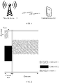
- FIG. 1 shows a communications system 100 applicable to this application.
- the communications system 100 includes a network device 110 and a terminal device 120, and the network device 110 communicates with the terminal device 120 by using a wireless network.
- a wireless communications module may encode information for transmission.
- the wireless communications module may obtain a particular quantity of data bits to be sent to the network device 110 by using a channel.
- These data bits are, for example, data bits that are generated by a processing module, received from another device, or stored in a storage module.
- These data bits may be included in one or more transport blocks (which may also be referred to as information blocks or data blocks), and the transport block may be segmented to generate a plurality of code blocks.
- the terminal device may be referred to as an access terminal, user equipment (user equipment, UE), a subscriber unit, a subscriber station, a mobile station, a mobile station, a remote station, a remote terminal, a mobile device, a user terminal, a terminal, radio communications equipment, a user agent, or a user apparatus.
- the access terminal may be a cellular phone, a handheld device or a computing device having a wireless communication function, another processing device connected to a wireless modem, an in-vehicle device, a wearable device, or user equipment in a 5G communications system.
- the network device may be a base transceiver station (base transceiver station, BTS) in a Code Division Multiple Access (code division multiple access, CDMA) system, a NodeB (node B, NB) in a Wideband Code Division Multiple Access (wideband code division multiple access, WCDMA) system, an evolved NodeB (evolutional node B, eNB) in a Long Term Evolution (long term evolution, LTE) system, or a gNB (gNB) in a 5G communications system.
- the foregoing base stations are merely examples for description.
- the network device may be a relay station, an access point, an in-vehicle device, a wearable device, or another type of device.
- the foregoing communications system applicable to this application is merely an example for description.
- a communications system applicable to this application is not limited thereto.
- the communications system may alternatively include another quantity of network devices and another quantity of terminal devices.
- a basic time unit for scheduling downlink resources is a slot (slot).
- One slot includes 7 or 14 symbols in time domain, and may be divided into a control area and a data area.
- the data area is used to send a physical downlink shared channel (physical downlink shared channel, PDSCH) that carries downlink data.
- the control area is used to send a physical downlink control channel (physical downlink control channel, PDCCH), and the PDCCH is used to carry downlink control information (downlink control information, DCI).
- a time-frequency resource used by the PDSCH includes one or more resource blocks (Resource Block, RB) in frequency domain. Each RB includes 12 consecutive subcarriers in frequency domain and one symbol in time domain.
- Resource Block Resource Block
- the DCI carried by the PDCCH includes information indicating a position of an RB(s) used by the PDSCH in time/frequency domain, namely, downlink resource allocation information.
- control resource set control resource set, CORESET.
- the UE can detect the PDCCH on the one or more CORESETs. As shown in FIG. 2 , there are two CORESETs in a control area of a slot, and the two CORESETs may occupy resources of different sizes in time domain and frequency domain.
- the PDCCH corresponds to one or more control channel elements (Control Channel Element, CCE).
- CCE Control Channel Element
- one PDCCH may correspond to 1, 2, 4, 8, or 16 CCEs.
- a quantity of CCE corresponding to one PDCCH is also referred to as an aggregation level of the PDCCH.
- a base station may select different aggregation levels based on channel statuses of the UE, so as to change a channel code rate corresponding to the PDCCH, thereby implementing link adaptation.
- Each CCE may include one or more resource element groups (Control Resource Element Group, REG), for example, six or four REGs.
- REG is used to define mapping of the PDCCH onto resource elements REs, equivalently, or define mapping of a CCE corresponding to the PDCCH onto REs.
- Each REG may correspond to one resource block (Resource Block, RB).
- An RB set that can be used by a control channel of each UE may be predefined, for example, bandwidth specified with respect to a carrier center is predefined to send or receive a control channel; or may be notified by using higher layer signaling, for example, a control resource set (control resource set, CORESET) of the UE is notified by using RRC signaling.
- Manner of mapping a CCE onto REGs include the following: a localized (localized) manner and a distributed (distributed) manner; a time-first (time-first) manner, and a frequency-first (frequency-first) manner.
- REGs included in a CCE are consecutive in frequency domain or time domain.
- REGs included in a CCE are discrete or partially consecutive in frequency domain or time domain.
- a CCE is mapped onto REGs first in time domain and then in frequency domain.
- a CCE is mapped onto REGs first in frequency domain and then in time domain.
- a plurality of REGs that are consecutive in frequency domain or time domain may form a REG set.
- a plurality of REGs that are consecutive in frequency domain or time domain are bundled (bundling) to form a REG bundle (bundle).
- the REG set or the REG bundle (bundle) may also be referred to as a REG group (group).
- a specific name of the REG set is not limited in this application. Because a PDCCH is mapped onto REGs by using a CCE(s), a plurality of REGs corresponding to each CCE are bundled (bundling) to form one or more REG sets.
- the UE can use an available DMRSs in the REG set instead of a single REG to perform joint channel estimation, thereby improving channel estimation precision.
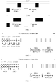
- FIG. 3 shows two possible DMRS patterns, and one REG includes two or four REs used for a DMRS.
- a same precoder may be used for a DMRS and DCI that are sent in a same REG on a DMRS-based control channel, so that the UE may directly obtain, from the DMRS, a channel estimate corresponding to the DCI.
- a precondition for using a DMRS in REGs in a REG set or a REG bundle to perform joint channel estimation is that the REGs included in the REG set or the REG bundle have channel correlation in time domain and/or frequency domain, so that the channel correlation in time domain and/or frequency domain can be used to perform joint channel estimation.
- a least square (Least Squared) or minimum mean square error (Minimum Mean Squared Error, MMSE) criterion is used to obtain a channel estimate.
- MMSE Minimum Mean Squared Error
- FIG. 4 shows a localized and frequency-first CCE-to-REG mapping method according to this application.
- a control channel includes two CCEs: a CCE 0 and a CCE 1.
- Each CCE includes six REGs, and a bundle size (bundling size) of the six REGs is three REGs in frequency domain and one REG in time domain.
- FIG. 5 shows another localized and frequency-first CCE-to-REG mapping method according to this application.
- a control channel includes two CCEs: a CCE 0 and a CCE 1.
- Each CCE includes six REGs, and a bundle size of the six REGs is six REGs in frequency domain and one REG in time domain.
- FIG. 6 shows a distributed and frequency-first CCE-to-REG mapping method according to this application.
- a control channel includes two CCEs: a CCE 0 and a CCE 1.
- Each CCE includes six REGs, and a bundle size of the six REGs is two REGs in frequency domain and one REG in time domain.
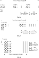
- FIG. 7 shows another distributed and frequency-first CCE-to-REG mapping method according to this application.
- a control channel includes two CCEs: a CCE 0 and a CCE 1.
- Each CCE includes six REGs, and a bundling size of the six REGs is three REGs in frequency domain and one REG in time domain.
- FIG. 8 shows a localized and time-first CCE-to-REG mapping method according to this application.
- a control channel includes two CCEs: a CCE 0 and a CCE 1.
- Each CCE includes six REGs, and a bundling size of the six REGs is two REGs in frequency domain and three REGs in time domain.
- FIG. 9 shows another localized and time-first CCE-to-REG mapping method according to this application.
- a control channel includes two CCEs: a CCE 0 and a CCE 1.
- Each CCE includes six REGs, and a bundling size of the six REGs is three REGs in frequency domain and two REGs in time domain.
- FIG. 10 shows a distributed and time-first CCE-to-REG mapping method according to this application.
- a control channel includes two CCEs: a CCE 0 and a CCE 1.
- Each CCE includes six REGs, and a bundling size of the six REGs is one REG in frequency domain and two REGs in time domain.
- FIG. 11 shows another distributed and time-first CCE-to-REG mapping method according to this application.
- a control channel includes two CCEs: a CCE 0 and a CCE 1.
- Each CCE includes six REGs, and a bundling size of the six REGs is one REG in frequency domain and three REGs in time domain.
- REG sets or REG bundles shown in FIG. 4 to FIG. 11 may be consecutive or inconsecutive in frequency domain.
- the bundle size limits a resource granularity based on which the control channel can be mapped in frequency domain or time domain.
- the bundle size in frequency domain is one REG
- the bundle size in time domain may be two or three REGs.
- the bundle size in time domain may be one or three REGs.
- the bundle size in time domain may be one or two REGs.
- the bundle size in frequency domain is six REGs
- the bundle size in time domain may be one REG.
- a REG set or REG bundle pattern in a specific implementation may be a pattern 0, 1, 2, or 3 shown in FIG. 12 ; or a REG set or REG bundle pattern in a specific implementation may be a pattern 0 or 1 shown in FIG. 13 ; or a REG set or REG bundle pattern in a specific implementation may be a pattern 0 or 1 shown in FIG. 14 .
- REGs given in each REG set or REG bundle pattern are consecutive in time and/or frequency.
- FIG. 15 shows a communication method according to this application, and the communication method may be performed by a base station.
- the method 100 includes the following steps.
- S110 Determine a quantity and a position of a CCE used by a control channel of user equipment UE, where each of the CCE corresponds to a plurality of resource element groups REGs, the plurality of REGs form at least one REG set, and any REG set in the at least one REG set includes a plurality of resource blocks RBs that are consecutive or adjacent in time domain or frequency domain.
- control channel may carry scheduling allocation information or other control information.
- control channel may be, for example, a PDCCH, or may be another control channel configured to transmit control information.
- a specific name of the control channel is not limited in this application.
- the quantity of a CCE used by the control channel of the user equipment UE may be determined by the base station based on a channel condition of the UE.
- the control channel of the user equipment UE may use 1, 2, 4, 8, or 16 CCEs. Different CCE quantities correspond to different code rates of the control channel.
- the base station may learn the channel condition, especially a signal to noise ratio SNR, of the UE based on a channel quality indicator (Channel Quality Indicator, CQI) fed back by the UE.
- CQI Channel Quality Indicator
- a quantity of CCEs required for meeting a performance requirement is obtained based on the SNR, a performance requirement on, for example, a block error rate BLER or a bit error rate BER, and channel coding performance such as an SNR vs BER curve of the control channel.
- the CCE used by the control channel of the user equipment UE may be a plurality of CCEs with a particular CCE index as a start position.
- the start position may be derived according to a predefined rule or function based on a UE identifier ID, a slot index, a symbol index, or an aggregation level.
- the start position may be derived according to an indexing function of a start position of an LTE PDCCH or an EPDCCH. Details are not further described herein.
- the solution in the present invention for determining the quantity and a position of a CCE may be flexibly selected based on an actual requirement on control information transmission. No limitation is imposed in the present invention.
- the quantity and positions of CCEs may be shown in FIG. 4 to FIG. 11 .
- REG indexes or numbers shown in FIG. 4 to FIG. 11 are numbered based on CCE indexes. The present invention is not limited by the numbering.
- the REG indexes may be numbered first in frequency domain and then in time domain in increasing order of frequency domain positions, or may be numbered first in time domain and then in frequency domain, specifically, provided that a CCE index is mapped onto related REG indexes.
- S120 Send the control channel to the user equipment UE by using the CCEs.
- the user equipment determines the quantity and a position of a control channel elements CCE used by the control channel of the UE, where each of the CCE corresponds to a plurality of resource element groups REGs, the plurality of REGs form at least one REG set, and any REG set in the at least one REG set includes a plurality of resource blocks RBs that are consecutive or adjacent in time domain or frequency domain.
- the user equipment determines the quantity and a position of a CCE based on different aggregation levels and a quantity of candidates of the control channel, and each aggregation level corresponds to different CCE quantities.
- each aggregation level corresponds to different CCE quantities.
- S140 The user equipment receives, by using the CCE, the control channel sent by the network device.
- each of the CCE corresponds to a plurality of resource element groups REGs, for example, the CCE may correspond to six or four REGs.
- the plurality of REGs form at least one REG set or REG bundle, and any REG set or REG bundle in the at least one REG set or REG bundle includes a plurality of resource blocks RBs that are consecutive or adjacent in time domain or frequency domain.
- the CCE respectively include two, one, three, and two REG sets or REG bundles, and each REG set or REG bundle includes three, six, three, or two REGs that are consecutive or adjacent in frequency domain.
- the CCE respectively include one, one, three, and two REG sets or REG bundles.
- Each REG set or REG bundle includes six, six, three, or two REGs that are consecutive or adjacent in time domain or in time domain and frequency domain.
- a plurality of REGs that are included in each REG set or REG bundle and that are consecutive or adjacent in time domain or frequency domain may form a different pattern in time domain or frequency domain.
- the REG sets or REG bundles thereof each include REGs that are consecutive or adjacent in frequency domain or time domain or in frequency domain and time domain.
- a REG in any REG set or REG bundle may correspond to one physical resource block RB.
- being adjacent in frequency domain means that a plurality of RBs configured for the control resource set may be inconsecutive in frequency domain but after the RBs are arranged in increasing or decreasing order in frequency domain, indexes of the RBs may be consecutive.
- being adjacent in time domain means that a plurality of RBs configured for the control resource set may be inconsecutive in time domain but after the RBs are arranged in increasing or decreasing order in time domain, indexes of the RBs may be consecutive.
- the REGs in the REG set or the REG bundle are consecutive or adjacent in at least one of dimensions of time domain and frequency domain, so that a plurality of DMRSs in bundled REGs may be used to perform joint channel estimation, thereby improving channel estimation precision.
- a channel estimate is usually obtained by using a channel estimation algorithm based on correlation in time and/or frequency between a position at which an RE corresponding to a DMRS is located and a position at which an RE corresponding to DCI is located.
- an actual channel estimation process usually includes two basic steps: First, obtain, by using the least square method based on a DMRS sequence predefined or known in advance, a channel estimate at a position at which an RE corresponding to a DMRS is located.
- Second derive, by using a minimum mean square error estimation algorithm based on correlation in time and/or frequency between a position at which the RE corresponding to the DMRS is located and a position at which an RE corresponding to DCI is located, a channel estimate at the position at which the RE corresponding to the DCI is located from the channel estimate at the position at which the RE corresponding to the DMRS is located.
- Correlation of the radio channels between different RE positions in time and/or frequency is usually obtained based on channel statistics.
- the correlation in frequency domain may be obtained based on multipath delay characteristics such as delay spread and variance.
- the correlation in time domain may be obtained based on multipath directional distribution and a Doppler frequency shift characteristic.
- the channel estimation algorithm based on the correlation in time or frequency belongs to the prior art.
- a specific implementation is not limited in the present invention.
- a channel estimate at a position at which an RE corresponding to DCI is located is usually a weighted combination of channel estimates at positions at which REs corresponding to DMRSs are located. More available DMRSs indicate that a channel estimate at the position at which the RE corresponding to the DCI is located can be determined more precisely by using the correlation in time domain or frequency domain.
- each of the CCE corresponds to a plurality of resource element groups REGs
- the plurality of REGs form at least one REG set
- any REG set in the at least one REG set includes a plurality of resource blocks RBs that are consecutive or adjacent in time domain or frequency domain.
- DMRSs in a plurality of consecutive or adjacent REGs in the REG set can be fully used, and DMRSs in a plurality of adjacent resource blocks in frequency domain and/or a plurality of symbols in time domain can be used to perform joint channel estimation, thereby greatly improving channel estimation performance.
- the sending the control channel to the user equipment UE by using the CCE may specifically include:
- the receiving, by the user equipment by using the CCE, the control channel sent by the network device specifically includes:
- control information carried by the control channel belongs to the prior art, and details are not described herein.
- the method 100 further includes the following steps.
- Step A The network device determines the at least one REG set from a control resource set based on a REG bundle size or a REG bundle pattern.
- the control resource set includes a resource block set used to send the control channel.
- Step B The user equipment determines the at least one REG set from a control resource set based on a REG bundle size or a REG bundle pattern.
- the control resource set includes a resource block set used to receive the control channel.
- control resource set may be predefined. For example, a plurality of consecutive or discrete RBs and a plurality of symbols in time are specified on predefined positions of a frequency band as a control resource set.
- the predefined control resource set may be specific for a frequency band (Band).
- control resource set may be notified to the UE by using signaling.
- a quantity, positions, and a time length of RBs included in the control resource set are notified to the UE by using RRC signaling.
- Specific positions of the RBs may be obtained by coding RB indexes by using generalized combinatorial numbers.
- the time length may be one, two, or three OFDM symbols.
- control resource set may be predefined. For example, a plurality of consecutive or discrete RBs and a plurality of symbols in time are specified on predefined positions of a frequency band as a control resource set.
- the predefined control resource set may be specific for a frequency band (Band).
- control resource set may alternatively be obtained in a manner of combining the foregoing two manners: predefining a plurality of frequency band (Band) specific control resource sets, and indicating one or more of the control resource sets by using RRC signaling.
- Band frequency band
- Each RB in the control resource set may correspond to one REG.
- REGs corresponding to the control resource set may be numbered first in frequency domain and then in time domain, and arranged in increasing order in frequency domain. For example, for a total of 48 RBs including 2 symbols in time domain and 24 RBs in frequency domain, numbering of REG indexes of the REGs is shown in FIG. 16 .
- the REGs corresponding to the control resource set may be numbered first in time domain and then in frequency domain, and arranged in increasing order in frequency domain. For example, for a total of 48 RBs including 2 symbols in time domain and 24 RBs in frequency domain, numbering of REG indexes of the REGs is shown in FIG. 17 .
- the following uses an example in which REGs are numbered first in frequency domain and then in time domain, and arranged in increasing order in frequency domain, but the present invention is not limited thereto.
- the REG bundle size may include a REG bundle size in frequency domain and/or a REG bundle size in time domain.
- the REG bundle size in frequency domain may be 2, 3, or 6, separately as shown in FIG. 6 , FIG. 4, and FIG. 5 .
- the REG bundle size in time domain may be 2 or 3, as shown in FIG. 10 and FIG. 11 .
- the REG bundle size in time domain and frequency domain may be 6, as shown in FIG. 8 and FIG. 9 .
- the REG bundle or the REG bundle pattern may be shown in FIG. 12, FIG. 13, and FIG. 14.
- FIG. 12 shows patterns of one, two, three, and six REGs bundled in frequency domain.
- FIG. 13 shows patterns of two symbols bundled in time domain and one or three REGs bundled in frequency domain.
- FIG. 14 shows patterns of three symbols bundled in time domain and one or two REGs bundled in frequency domain.
- the REG bundle size is predefined, for example, may be predefined based on a control resource set, namely, a control resource set specific REG bundle size; or may be predefined based on search space, for example, a common search space specific REG bundle size or a UE-specific search space specific REG bundle size.
- the REG bundle pattern may be predefined, as shown by patterns in FIG. 12, FIG. 13, and FIG. 14 .
- a quantity of REGs that are consecutive or adjacent in frequency domain or time domain may be obtained from the REG bundle size or the REG bundle pattern.
- the REG bundle size or the REG bundle pattern may be predefined based on the control resource set or the search space, and therefore is known to both the base station and the user equipment.
- the REG bundle size or the REG bundle pattern may alternatively be notified by the base station to the UE by using signaling, for example, notified to the UE by using higher layer signaling such as RRC signaling. Specifically, for example, the REG bundle size or the REG bundle pattern may be notified to the UE based on the control resource set or search space configuration information.
- any REG set in the at least one REG set meets at least one of the following conditions: m consecutive or adjacent PRBs in frequency domain, where m is a positive integer; or n consecutive or adjacent symbols in time domain, where n is a positive integer.
- a value of m may be 1, 2, 3, 6, 12, or the like; or 2, 4, 8, or 16.
- a value of n may be 1, 2, 3, or the like.
- the determining the at least one REG set from the control resource set based on the REG bundle size or the preset REG bundle pattern may specifically include:
- REGs in a control resource set shown in FIG. 16 are bundled based on a bundle size of 2 in frequency domain or a REG bundle pattern 1 shown in FIG. 18 , to obtain 24 REG sets or REG bundles shown in FIG. 18 .
- a REG set or REG bundle 0 includes a REG 0 and a REG 1;
- a REG set or REG bundle 1 includes a REG 2 and a REG 3; and so on.
- REGs in a control resource set shown in FIG. 16 are bundled based on a bundle size of 3 in frequency domain and a bundle size of 2 in time domain, or a REG bundle pattern 1 shown in FIG. 19 , to obtain eight REG sets or REG bundles shown in FIG. 19 .
- a REG set or REG bundle 0 includes REGs 0, 1, 2, 24, 25, and 26;
- a REG set or REG bundle 1 includes REGs 3, 4, 5, 27, 28, and 29; and so on.
- time-frequency positions of the plurality of REGs corresponding to each CCE are determined based on REG indexes corresponding to each CCE index.
- a CCE index may correspond to a plurality of consecutive REG indexes in sequence (in sequence).
- a CCE index corresponds to six consecutive REG indexes in sequence.
- CCE index of each of the CCE corresponds to at least one interleaved REG index
- the interleaved REG index is obtained based on the REG bundle size or the REG bundle pattern or the REG set.
- the interleaved REG index is obtained by interleaving REG indexes corresponding to the control resource set based on the REG bundle size or the REG bundle pattern.
- the interleaved REG index is obtained by interleaving REG indexes corresponding to the control resource set based on the REG set or the REG bundle.
- a control resource set and a REG bundle size or a REG bundle pattern in FIG. 18 are used as an example.
- a REG set or a REG bundle that is formed based on the REG bundle size or the REG bundle pattern may be used as an interleaving granularity, to form 24 REG sets or REG bundles, and each CCE corresponds to three REG sets or REG bundles, that is, six REGs.
- That a REG set or a REG bundle is used as an interleaving granularity means that REG indexes corresponding to the REG set or the REG bundle form an N-tuple, where N is a quantity of REGs corresponding to the REG set or the REG bundle, and all N-tuples are interleaved.
- performing interleaving by using the REG set or the REG bundle as an interleaving granularity may include:
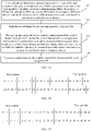
- a row-in column-out interleaver may be used, and inter-column re-arrangement based on bit inversion may be used.
- a principle of the interleaver is similar to that of an interleaver used for an LTE convolutional code or Turbo code. Specifically, the principle includes:
- the inter-column interleaving pattern may be based on bit inversion (bit reverse).
- bit inversion bit reverse
- a column interleaving pattern corresponding to 32 columns is as follows, where ⁇ P (0), P (1),..., P ( N C -1)> is column position indexes obtained after interleaving.
- REG set or REG bundle indexes corresponding to CCE 0 are 0, 16, and 8 in sequence, which correspond to REG indexes of 0, 1, 32, 33, 16, and 17.
- REGs or REG sets or REG bundles corresponding to a CCE or a control channel are distributed in different times or frequencies, so that time or frequency selectivity of a radio channel can be fully used. Therefore, a time or frequency diversity gain can be obtained.
- REGs on each symbol in a control resource set may be interleaved by using an interleaver based on a REG bundle size or a REG bundle pattern.
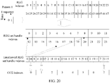
- REGs on two symbols shown in FIG. 18 are separately interleaved by using the foregoing interleaver to obtain REG set or REG bundle indexes and corresponding REG indexes, as shown in FIG. 21 .
- frequency-first CCE-to-REG mapping can be implemented.
- REGs or REG sets or REG bundles corresponding to a CCE or a control channel are distributed on a same symbol but in different frequencies. A frequency diversity gain can be obtained.
- the control channel may be located on a single symbol, so that fast hybrid automatic repeat request (HARQ)-acknowledgment/negative acknowledgment (ACK/NACK) feedback can be implemented. Moreover, this is particularly applicable to a URLLC service scenario.
- HARQ fast hybrid automatic repeat request
- ACK/NACK acknowledgement/negative acknowledgment
- time-first CCE-to-REG mapping can be implemented based on a REG bundle size or a REG bundle pattern. As shown in FIG. 22 , a REG bundle pattern corresponds to two REGs bundled in time domain. All REGs in a control resource set are interleaved based on a REG bundle size or a REG bundle pattern. In this embodiment, time-first CCE-to-REG mapping can be implemented.
- REGs or REG sets or REG bundles corresponding to a CCE or a control channel can implement time-first CCE-to-REG mapping.
- a frequency diversity gain can be obtained.
- a control channel may be located on different symbols, and power headroom on the symbols can be used to perform power boosting (power boosting) on the control channel, especially on a DMRS on the control channel, thereby improving channel estimation performance and enhancing control channel coverage.
- frequency-first CCE-to-REG mapping can be implemented based on a REG bundle size or a REG bundle pattern in time domain and frequency domain.
- a REG bundle pattern corresponds to two REGs bundled in time domain and three REGs bundled in frequency domain. All REGs in a control resource set are interleaved based on a REG bundle size or a REG bundle pattern, thereby actually implementing CCE-granularity interleaving.
- REGs corresponding to a control resource set are interleaved by using a REG set or a REG bundle as an interleaving granularity based on a REG bundle size or a REG bundle pattern.
- DMRSs in the REG set or the REG bundle can be used to perform joint channel estimation, thereby improving channel estimation precision.
- a case in which different REGs in a REG set or a REG bundle are distributed on different CCEs is effectively avoided, thereby effectively decreasing receiving complexity.
- the REG bundle is used as an interleaving granularity may be predefined or obtained through configuration, so that a resource granularity of the control channel can match that of a data channel.
- a CCE actually used to send the control channel may occupy only some of time-frequency resources in a control channel resource set in most cases, or may occupy all the time-frequency resources.
- a reference signal used to demodulate the control channel and DCI are located only in a control area in which a control resource set is located.
- a base station does not send the reference signal and the DCI in a time-frequency resource area in which the control channel is sent. Therefore, in the control channel resource set, if a CCE actually used to send the control channel does not occupy all the time-frequency resources in the control channel resource set, remaining control channel resources in the control channel resource set can be used to send a PDSCH.
- a CCE actually used to receive the control channel may occupy only some of time-frequency resources in a control channel resource set in most cases, or may occupy all the time-frequency resources.
- a reference signal used to demodulate the control channel and DCI are located only in a control area in which a control resource set is located.
- the base station does not send the reference signal and the DCI in a time-frequency resource area in which the control channel is sent. Therefore, in the control channel resource set, if a CCE actually used to receive the control channel does not occupy all the time-frequency resources in the control channel resource set, remaining control channel resources in the control channel resource set can be used to receive a PDSCH.
- that the interleaved REG indexes are obtained based on the REG bundle size or the REG bundle pattern or the REG set may further include: grouping, based on the REG bundle size or the REG bundle pattern or the REG set, REG indexes corresponding to the control resource set, where REG indexes included in each group correspond to a plurality of REG sets or REG bundles.
- a set of REGs in one group and a set of REGs in another group may overlap, or may not overlap.
- REG indexes in each group are interleaved based on the REG bundle size or the REG bundle pattern or the REG set. Specifically, REGs in a group may be interleaved by using a REG set or REG bundle as a granularity. Interleaved REG indexes are obtained from the interleaved REG set or REG bundle index.
- the method 100 includes the following steps:
- REGs in each group may be interleaved by using the foregoing row-in-column-out interleaver and by using a REG set or a REG bundle as a granularity, and columns may be re-arranged. Details are not further described herein.
- REGs corresponding to the control resource set are grouped based on the REG bundle size or the REG bundle pattern, and interleaving is performed within each group by using a REG set or a REG bundle as a granularity.
- DMRSs in the REG set or the REG bundle can be used to perform joint channel estimation, thereby improving channel estimation precision.
- resource conflicts between CCEs corresponding to different groups can be effectively reduced, thereby effectively avoiding a resource collision between different control channels.
- the REG bundle is used as an interleaving granularity may be predefined or obtained through configuration, so that a resource granularity of the control channel can match that of a data channel.
- the control channel and the data channel can be coordinated to respectively reuse different control resource areas, thereby effectively improving resource use efficiency.
- manners of grouping and interleaving REG sets or REG bundles corresponding to the control resource set based on the REG bundle size or the REG bundle pattern include but are not limited to the following two manners: Manner 1: REGs on each symbol of the control resource set are interleaved respectively.
- REGs on each symbol of the control resource set form a group.
- the REGs on each symbol are interleaved based on the REG bundle size or the REG bundle pattern by using a REG set or REG bundle as an interleaving granularity.
- REGs on two symbols shown in FIG. 18 are separately interleaved by using the foregoing interleaver to obtain REG set or REG bundle indexes and corresponding REG indexes, as shown in FIG. 21 .
- frequency-first CCE-to-REG mapping can be implemented.
- REGs or REG sets or REG bundles corresponding to a CCE or a control channel are distributed on a same symbol but in different frequencies.
- a frequency diversity gain can be obtained.
- the control channel may be located on a single symbol, so that fast hybrid automatic repeat request (HARQ)-acknowledgment/negative acknowledgment (ACK/NACK) feedback can be implemented.
- HARQ fast hybrid automatic repeat request
- ACK/NACK acknowledgenowledgment/negative acknowledgment
- Manner 2 grouping with equal-space is performed, based on a REG set, on all REGs corresponding to the control resource set, and interleaving is performed within each group by using the REG set as a granularity.
- a REG bundle size of 3 in frequency domain or a bundle size of 3 in frequency domain in a REG bundle pattern is used as an example, as shown in FIG. 24 .
- a REG bundle size of 2 in frequency domain or a bundle size of 2 in frequency domain in a REG bundle pattern is used as an example, as shown in FIG. 25 .
- a REG bundle size of 2 or 3 in time domain or a bundle size of 2 or 3 in time domain in a REG bundle pattern is used as an example, as shown in FIG. 26 .
- a REG bundle size of 4 in frequency domain or a bundle size of 4 in frequency domain in a REG bundle pattern is used as an example, as shown in FIG. 27 .
- a REG bundle size of 2 in frequency domain or a bundle size of 2 in frequency domain in a REG bundle pattern is used as an example, as shown in FIG. 28 .
- a REG bundle size of 2 or 3 in time domain or a bundle size of 2 or 3 in time domain in a REG bundle pattern is used as an example, as shown in FIG. 29 .
- each group can be independently interleaved.
- only one of the groups may be interleaved, and another group is derived by performing cyclic shifting on an index obtained based on an interleaved group, and an offset equal to a group length is introduced.
- REG indexes after a group 1 is interleaved are 0, 8, 4, 2, 10, 6, 1, 9, 5, 3, 11, and 7; and indexes of a group 2 may be 3+12, 11+12, 7+12, 0+12, 8+12, 4+12, 2+12, 10+12, 6+12, 1+12, 9+12, and 5+12.
- 5G NR allows a traffic channel to reuse resources of a control channel.
- a base station configures, by using higher layer signaling such as Radio Resource Control (Radio Resource Control, RRC) signaling, a control resource set (Control Resource Set, CORESET) that can be used by user equipment (User Equipment, UE).
- RRC Radio Resource Control
- CORESET Control Resource Set
- Each occasion of sending a control channel depends on a channel condition and a control channel format or a payload (payload), and a physical resource actually used by the control channel may be a part of the configured control resource set CORESET.
- another resource in the control resource set CORESET can be used for the traffic channel such as a downlink shared channel (Physical Downlink Shared Channel, PDSCH).
- PDSCH Physical Downlink Shared Channel
- the REGs corresponding to the control resource set are grouped based on the REG bundle size or the REG bundle pattern, and interleaving is performed within each group by using a REG set or a REG bundle as a granularity.
- a DMRS in the REG set or the REG bundle can be used to perform joint channel estimation, thereby improving channel estimation precision.
- resource conflicts between CCEs corresponding to different groups can be effectively reduced, thereby effectively avoiding a resource collision between different control channels.
- the REG bundle is used as an interleaving granularity may be predefined or obtained through configuration, so that a resource granularity of the control channel can match that of the data channel. Furthermore, through grouping, the control channel and the data channel can be coordinated to respectively reuse different control resource areas, thereby effectively improving resource use efficiency.
- REGs corresponding to the control resource set may alternatively be grouped and interleaved based on configuration information of the control resource set, to obtain interleaved REG indexes.
- the configuration information of the control resource set may be the REG bundle size or the REG bundle pattern or a quantity of resource blocks or symbols in the control resource set.
- the base station uses an interleaver to perform the grouping and interleaving.
- the method 100 further includes the following steps:
- the REGs corresponding to the control resource set are grouped based on the REG bundle size or the REG bundle pattern, and interleaving is performed within each group by using a REG set or a REG bundle as a granularity.
- a DMRS in the REG set or the REG bundle can be used to perform joint channel estimation, thereby improving channel estimation precision.
- resource conflicts between CCEs corresponding to different groups can be effectively reduced, thereby effectively avoiding a resource collision between different control channels.
- the REG bundle is used as an interleaving granularity may be predefined or obtained through configuration, so that a resource granularity of the control channel can match that of a data channel.
- the control channel and the data channel can be coordinated to respectively reuse different control resource areas, thereby effectively improving resource use efficiency.
- step C and step D described above may be performed by the network device, or may be performed by the user equipment.
- FIG. 30 is a schematic diagram of a network device 400 according to an embodiment of this application.
- the network device 400 can be applied to the scenario shown in FIG. 1 , and configured to perform the method 100 corresponding to FIG. 15 .
- the network device 400 includes a processing unit 401 and a transceiver unit 402.
- the transceiver unit 402 may be specifically configured to perform various information transmitting and receiving that are performed by the network device in the method 100.
- the processing unit 401 is specifically configured to perform other processing that is performed by the network device in the method 100 and that is different from information transmitting and receiving.
- the processing unit 401 is configured to determine a quantity and a position of a control channel element CCE used by a control channel of user equipment, where each of the CCE corresponds to a plurality of resource element groups REGs, the plurality of REGs form at least one REG set, any REG set in the at least one REG set includes a plurality of physical resource blocks PRBs that are consecutive in at least one dimensions of time domain and frequency domain, REGs in any REG set are in one-to-one correspondence with the PRBs, and the plurality of PRBs belong to a control channel resource set.
- the transceiver unit 402 is configured to send control information to the user equipment by using the CCE determined by the processor.
- a network device 500 may include a processor 501, a transceiver 502, and a memory 503.
- the memory 503 may be configured to store a program/code preinstalled on the network device 500 at delivery, or may store code executed by the processor 501, and the like.
- the network device 500 in this embodiment of this application may correspond to the network device in the method 100 in the embodiment of this application.
- the transceiver 502 is configured to perform various information transmitting and receiving that are performed by the network device in the method 100.
- the processor 501 is configured to perform other processing that is performed by the network device in the method 100 and that is different from information transmitting and receiving. Details are not described herein again.
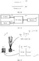
- FIG. 32 is a schematic structural diagram of a network device 20.
- the network device 20 may be, for example, a base station.
- the network device 20 can be applied to the system shown in FIG. 1 , to perform the method corresponding to FIG. 15 .
- the network device 20 includes one or more remote radio units (English: remote radio unit, RRU for short) 201 and one or more baseband units (English: baseband unit, BBU for short) 202.
- the RRU 201 may be referred to as a transceiver unit, a transceiver, a transceiver circuit, a transceiver device, or the like, and may include at least one antenna 2011 and a radio frequency unit 2012.
- the RRU 201 is mainly configured to transmit and receive a radio frequency signal and perform conversion between a radio frequency signal and a baseband signal.
- the RRU 201 is configured to perform various information transmitting and receiving that are performed by the network device in the foregoing method 200 or 300.
- the BBU 202 is mainly configured to perform baseband processing, control the network device, and the like.
- the RRU 201 and the BBU 202 may be physically disposed together, or may be physically disposed separately, for example, may be on distributed base stations.
- the BBU 202 is a control center of the network device, and may also be referred to as a processing unit.
- the BBU 202 is mainly configured to complete baseband processing functions, such as channel coding, multiplexing, modulation, and spectrum spreading.
- the BBU processing unit
- the BBU may be configured to control the network device to perform other processing that is different from information transmitting and receiving in the method 100.
- the BBU 202 may include one or more boards.
- a plurality of boards can jointly support a radio access network (such as an LTE network) in a single access standard, or may support radio access networks in different access standards.
- the BBU 202 may further include a memory 2021 and a processor 2022.
- the memory 2021 is configured to store necessary instructions and data.
- the memory 2021 stores the codebooks C1 and C2 and/or the codebook C in the foregoing embodiment.
- the processor 2022 is configured to control the network device to perform a necessary action, for example, configured to control the network device to perform other processing that is different from information transmitting and receiving in the foregoing method 200 or 300.
- the memory 2021 and the processor 2022 can serve one or more boards. To be specific, a memory and a processor may be separately disposed on each board. Alternatively, a plurality of boards may share a same memory and a same processor. In addition, a necessary circuit is further disposed on each board.
- FIG. 33 is a schematic diagram of a terminal device 600 according to an embodiment of this application.
- the terminal device 600 can be applied to the scenario shown in FIG. 1 , to perform the method corresponding to FIG. 15 .
- the terminal device 600 includes a processing unit 601 and a transceiver unit 602.
- the transceiver unit 602 may be specifically configured to perform various information transmitting and receiving that are performed by the terminal device in the method 100.
- the processing unit 601 is specifically configured to perform other processing that is performed by the terminal device in the method 100 and that is different from information transmitting and receiving.
- the processing unit 601 is configured to determine a quantity and a position of a control channel element CCE used by a control channel of the communication apparatus, where each of the CCE corresponds to a plurality of resource element groups REGs, the plurality of REGs form at least one REG set, any REG set in the at least one REG set includes a plurality of physical resource blocks PRBs that are consecutive in at least one dimensions of time domain and frequency domain, REGs in any REG set are in one-to-one correspondence with the PRBs, and the plurality of PRBs belong to a control channel resource set.
- the transceiver unit 602 is configured to receive control information from the network device by using the CCE determined by the processor.
- a terminal device 700 may include a processor 701, a transceiver 702, and a memory 703.
- the memory 703 may be configured to store a program/code preinstalled on the terminal device 700 at delivery, or may store code executed by the processor 701, and the like.
- the terminal device 700 in this embodiment of this application may correspond to the terminal device in the method 100 in the embodiment of this application.
- the transceiver 702 is configured to perform various information transmitting and receiving that are performed by the terminal device in the method 100.
- the processor 701 is configured to perform other processing that is performed by the terminal device in the method 100 and that is different from information transmitting and receiving. Details are not described herein again.
- FIG. 35 is a schematic structural diagram of a terminal device.
- the terminal device can be applied to the scenario shown in FIG. 1 , to perform the method corresponding to FIG. 15 .
- FIG. 35 shows only main components of the terminal device.
- a terminal device 10 includes a processor, a memory, a control circuit, an antenna, and an input/output apparatus.
- the control circuit is mainly configured to perform conversion between a baseband signal and a radio frequency signal, and process the radio frequency signal.
- the control circuit and the antenna together may also be referred to as a transceiver device, mainly configured to transmit and receive a radio frequency signal in a form of an electromagnetic wave, and receive a signaling instruction and/or a reference signal sent by a base station, and configured to perform various information transmitting and receiving that are performed by the terminal device in the foregoing method 100.
- the processor is mainly configured to process a communications protocol and communication data, control the entire terminal device, execute a software program, and process data of the software program, for example, configured to support the terminal device in performing an action different from information transmitting and receiving in the method 100.
- the memory is mainly configured to store a software program and data.
- the input/output apparatus such as a touchscreen, a display, or a keyboard is mainly configured to receive data input by a user and output data to the user.
- the processor can read a software program in a storage unit, interpret and execute an instruction of the software program, and process data of the software program.
- the processor performs baseband processing on the to-be-sent data, and then outputs a baseband signal to a radio frequency circuit.
- the radio frequency circuit performs radio frequency processing on the baseband signal, and then sends the radio frequency signal in a form of an electromagnetic wave by using an antenna.
- the radio frequency circuit receives a radio frequency signal by using the antenna, converts the radio frequency signal into a baseband signal, and outputs the baseband signal to the processor.
- the processor converts the baseband signal into data and processes the data.
- FIG. 35 shows only one memory and one processor. In actual user equipment, there may be a plurality of processors and memories.
- the memory may also be referred to as a storage medium or a storage device. This is not limited in this embodiment of this application.
- the processor may include a baseband processor and a central processing unit.
- the baseband processor is mainly configured to process a communications protocol and communication data.
- the central processing unit is mainly configured to control the entire terminal device, execute a software program, and process data of the software program. Functions of the baseband processor and the central processing unit are integrated in the processor in FIG. 9 .
- the baseband processor and the central processing unit may alternatively be independent processors connected to each other by using technologies such as a bus.
- the terminal device may include a plurality of baseband processors, to adapt to different network standards.
- the terminal device may include a plurality of central processing units to enhance a processing capability of the terminal device.
- the baseband processor may also be described as a baseband processing circuit or a baseband processing chip.
- the central processing unit may also be described as a central processing circuit or a central processing chip. Functions of processing the communications protocol and the communication data may be built in the processor, or may be stored in a storage unit in a form of a software program, and the processor executes the software program to implement baseband processing functions.
- an antenna having transmitting and receiving functions and a control circuit may be considered as a transceiver unit 101 of the terminal device 10, and a processor having a processing function may be considered as a processing unit 102 of UE 10.
- the terminal device 10 includes the transceiver unit 101 and the processing unit 102.
- the transceiver unit may also be referred to as a transceiver device, a transceiver, a transceiver apparatus, or the like.
- a device, configured to implement a receiving function, in the transceiver unit 101 may be considered as a receiving unit, and a device, configured to implement a transmitting function, in the transceiver unit 101 may be considered as a transmitting unit.
- the transceiver unit 101 includes a receiving unit and a transmitting unit.
- the receiving unit may also be referred to as a receiver, a receiving device, a receiving circuit, or the like.
- the transmitting unit may be referred to as a transmitter, a transmitting device, a transmitting circuit, or the like.
- the transceiver may be a wired transceiver, a wireless transceiver, or a combination thereof.
- the wired transceiver may be, for example, an Ethernet interface.
- the Ethernet interface may be an optical interface, an electrical interface, or a combination thereof.
- the wireless transceiver may be, for example, a wireless local area network transceiver, a cellular network transceiver, or a combination thereof.
- the processor may be a central processing unit (English: central processing unit, CPU for short), a network processor (English: network processor, NP for short), or a combination of the CPU and the NP.
- the processor may further include a hardware chip.
- the hardware chip may be an application-specific integrated circuit (English: application-specific integrated circuit, ASIC for short), a programmable logic device (English: programmable logic device, PLD for short), or a combination thereof.
- the PLD may be a complex programmable logic device (English: complex programmable logic device, CPLD for short), a field-programmable gate array (English: field-programmable gate array, FPGA for short), a generic array logic (English: generic array logic, GAL for short), or any combination thereof.
- the memory may include a volatile memory (English: volatile memory), for example, a random access memory (English: random-access memory, RAM for short).
- the memory may also include a nonvolatile memory (English: non-volatile memory), for example, a read-only memory (English: read-only memory, ROM for short), a flash memory (English: flash memory), a hard disk (English: hard disk drive, HDD for short) or a solid state disk (English: solid-state drive, SSD for short).
- a nonvolatile memory English: non-volatile memory
- a read-only memory English: read-only memory, ROM for short
- a flash memory English: flash memory
- a hard disk English: hard disk drive, HDD for short
- SSD solid state disk
- the memory may further include a combination of the foregoing types of memories.
- a bus interface may be further included.
- the bus interface may include any quantity of interconnected buses and bridges, specifically, one or more processors represented by the processor and various circuits of memories represented by the memory are connected together.
- the bus interface may further connect various other circuits such as a peripheral device, a voltage stabilizer, and a power management circuit together, which is well known in the art. Therefore, details are not further described in this specification.
- the bus interface provides an interface.
- the transceiver provides a unit configured to communicate with various other devices on a transmission medium.
- the processor is responsible for bus architecture management and general processing, and the memory can store data used by the processor for performing an operation.
- the various illustrative logical units and circuits described in the embodiments of the present invention may implement or operate the described functions by using a general processor, a digital signal processor, an application-specific integrated circuit (ASIC), a field programmable gate array (FPGA) or another programmable logical apparatus, a discrete gate or transistor logic, a discrete hardware component, or a design of any combination thereof.
- the general processor may be a microprocessor. In a specific implementation, the general processor may also be any conventional processor, controller, microcontroller, or state machine.
- the processor may also be implemented by a combination of computing apparatuses, such as a digital signal processor and a microprocessor, a plurality of microprocessors, one or more microprocessors with a digital signal processor core, or any other similar configuration.
- Steps of the methods or algorithms described in the embodiments of this application may be directly embedded into hardware, a software unit executed by a processor, or a combination thereof.
- the software unit may be stored in a RAM memory, a flash memory, a ROM memory, an EPROM memory, an EEPROM memory, a register, a hard disk, a removable magnetic disk, a CD-ROM, or a storage medium of any other form in the art.
- the storage medium may connect to a processor, so that the processor may read information from the storage medium and write information to the storage medium.
- the storage medium may also be integrated into the processor.
- the processor and the storage medium may be disposed in an ASIC, and the ASIC may be disposed in UE.
- the processor and the storage medium may also be disposed in different components of the UE.
- sequence numbers of the foregoing processes do not mean execution sequences in various embodiments of this application.
- the execution sequences of the processes should be determined according to functions and internal logic of the processes, and should not be construed as any limitation on the implementation processes of the embodiments of this application.
- All or some of the foregoing embodiments may be implemented by using software, hardware, firmware, or any combination thereof.
- the embodiments may be implemented completely or partially in a form of a computer program product.
- the computer program product includes one or more computer instructions.
- the computer may be a general-purpose computer, a dedicated computer, a computer network, or other programmable apparatuses.
- the computer instructions may be stored in a computer-readable storage medium or may be transmitted from a computer-readable storage medium to another computer-readable storage medium.
- the computer instructions may be transmitted from a website, computer, server, or data center to another website, computer, server, or data center in a wired (for example, a coaxial cable, an optical fiber, or a digital subscriber line (DSL)) or wireless (for example, infrared, radio, or microwave) manner.
- the computer-readable storage medium may be any usable medium accessible by a computer, or a data storage device, such as a server or a data center, integrating one or more usable media.
- the usable medium may be a magnetic medium (for example, a floppy disk, a hard disk, or a magnetic tape), an optical medium (for example, a DVD), a semiconductor medium (for example, a solid state disk Solid State Disk (SSD)), or the like.
- a magnetic medium for example, a floppy disk, a hard disk, or a magnetic tape
- an optical medium for example, a DVD
- a semiconductor medium for example, a solid state disk Solid State Disk (SSD)
- Embodiment 1 A communication method, comprising:
- Embodiment 2 The method according to embodiment 1, further comprising: determining the at least one REG set from a control resource set based on a REG bundle size or a REG bundle pattern, wherein the control resource set comprises a resource block RB set used to send the control channel, the RB set comprises the plurality of RBs, each RB corresponds to one REG, and REGs corresponding to the control resource set are numbered first in time domain and then in frequency domain, and arranged in increasing order of frequency domain.
- the control resource set comprises a resource block RB set used to send the control channel
- the RB set comprises the plurality of RBs, each RB corresponds to one REG
- REGs corresponding to the control resource set are numbered first in time domain and then in frequency domain, and arranged in increasing order of frequency domain.
- Embodiment 3 The method according to embodiment 2, wherein
- Embodiment 4 The method according to any one of embodiments 1 to 3, wherein the REG bundle size or the REG bundle pattern is predefined based on the control resource set or notified by a base station by using higher layer signaling.
- Embodiment 5 The method according to any one of embodiments 1 to 4, wherein REG indexes corresponding to a CCE index x in the CCE are 6x, 6x+1, 6x+2, 6x+3, 6x+4, and 6x+5.
- Embodiment 6 The method according to any one of embodiments 1 to 5, wherein CCE index of each of the CCE corresponds to a plurality of interleaved REG indexes, and the plurality of interleaved REG indexes are obtained based on the REG bundle size or the REG bundle pattern or the REG set.
- Embodiment 7 The method according to embodiment 6, wherein the plurality of interleaved REG indexes are obtained by interleaving, based on the REG bundle size or the REG bundle pattern or the REG set, REG indexes corresponding to the control resource set, wherein a REG set formed based on the REG bundle size or the REG bundle pattern is used as an interleaving granularity.
- Embodiment 8 The method according to embodiment 7, wherein the performing interleaving by using the REG set as the interleaving granularity specifically comprises:
- Embodiment 9 A communication method, comprising:
- Embodiment 10 The method according to embodiment 9, further comprising: determining the at least one REG set from a control resource set based on a REG bundle size or a REG bundle pattern, wherein the control resource set comprises a resource block RB set used to receive the control channel, the RB set comprises the plurality of RBs, each RB corresponds to one REG, and REGs corresponding to the control resource set are numbered first in time domain and then in frequency domain, and arranged in increasing order of frequency domain.
- the control resource set comprises a resource block RB set used to receive the control channel
- the RB set comprises the plurality of RBs, each RB corresponds to one REG
- REGs corresponding to the control resource set are numbered first in time domain and then in frequency domain, and arranged in increasing order of frequency domain.
- Embodiment 11 The method according to embodiment 10, wherein
- Embodiment 12 The method according to any one of embodiments 9 to 11, wherein the REG bundle size or the REG bundle pattern is predefined based on the control resource set or notified by a base station by using higher layer signaling.
- Embodiment 13 The method according to any one of embodiments 9 to 12, wherein REG indexes corresponding to a CCE index x in the CCE are 6x, 6x+1, 6x+2, 6x+3, 6x+4, and 6x+5.
- Embodiment 14 The method according to any one of embodiments 9 to 13, wherein CCE index of each of the CCE corresponds to a plurality of interleaved REG indexes, and the plurality of interleaved REG indexes are obtained based on the REG bundle size or the REG bundle pattern or the REG set.
- Embodiment 15 The method according to embodiment 14, wherein the plurality of interleaved REG indexes are obtained by interleaving, based on the REG bundle size or the REG bundle pattern or the REG set, REG indexes corresponding to the control resource set, wherein a REG set formed based on the REG bundle size or the REG bundle pattern is used as an interleaving granularity.
- Embodiment 16 The method according to embodiment 15, wherein the performing interleaving by using the REG set as the interleaving granularity specifically comprises:
- Embodiment 17 A network device, comprising a processor and a transceiver, wherein
- Embodiment 18 The network device according to embodiment 17, wherein the processor is further configured to: determine the at least one REG set from a control resource set based on a REG bundle size or a REG bundle pattern, wherein the control resource set comprises a resource block RB set used to send the control channel, the RB set comprises the plurality of RBs, each RB corresponds to one REG, and REGs corresponding to the control resource set are numbered first in time domain and then in frequency domain, and arranged in increasing order of frequency domain.
- the control resource set comprises a resource block RB set used to send the control channel
- the RB set comprises the plurality of RBs
- each RB corresponds to one REG
- REGs corresponding to the control resource set are numbered first in time domain and then in frequency domain, and arranged in increasing order of frequency domain.
- Embodiment 19 The network device according to embodiment 18, wherein
- Embodiment 20 The network device according to any one of embodiments 17 to 19, wherein the REG bundle size or the REG bundle pattern is predefined based on the control resource set or notified by a base station by using higher layer signaling.
- Embodiment 21 The network device according to any one of embodiments 17 to 20, wherein REG indexes corresponding to a CCE index x in the CCE are 6x, 6x+1, 6x+2, 6x+3, 6x+4, and 6x+5.
- Embodiment 22 The network device according to any one of embodiments 17 to 21, wherein CCE index of each of the CCE corresponds to a plurality of interleaved REG indexes, and the plurality of interleaved REG indexes are obtained based on the REG bundle size or the REG bundle pattern or the REG set.
- Embodiment 23 The network device according to embodiment 22, wherein the plurality of interleaved REG indexes are obtained by interleaving, based on the REG bundle size or the REG bundle pattern or the REG set, REG indexes corresponding to the control resource set, wherein a REG set formed based on the REG bundle size or the REG bundle pattern is used as an interleaving granularity.
- Embodiment 24 The network device according to embodiment 23, wherein the processor is specifically configured to:
- Embodiment 25 User equipment, comprising a processor and a transceiver, wherein
- Embodiment 26 The user equipment according to embodiment 25, wherein the processor is further configured to: determine the at least one REG set from a control resource set based on a REG bundle size or a REG bundle pattern, wherein the control resource set comprises a resource block RB set used to receive the control channel, the RB set comprises the plurality of RBs, each RB corresponds to one REG, and REGs corresponding to the control resource set are numbered first in time domain and then in frequency domain, and arranged in increasing order of frequency domain.
- the control resource set comprises a resource block RB set used to receive the control channel
- the RB set comprises the plurality of RBs, each RB corresponds to one REG
- REGs corresponding to the control resource set are numbered first in time domain and then in frequency domain, and arranged in increasing order of frequency domain.
- Embodiment 27 The user equipment according to embodiment 26, wherein
- Embodiment 28 The user equipment according to any one of embodiments 25 to 27, wherein the REG bundle size or the REG bundle pattern is predefined based on the control resource set or notified by a base station by using higher layer signaling.
- Embodiment 29 The user equipment according to any one of embodiments 25 to 28, wherein REG indexes corresponding to a CCE index x in the CCE are 6x, 6x+1, 6x+2, 6x+3, 6x+4, and 6x+5.
- Embodiment 30 The user equipment according to any one of embodiments 25 to 29, wherein CCE index of each of the CCE corresponds to a plurality of interleaved REG indexes, and the plurality of interleaved REG indexes are obtained based on the REG bundle size or the REG bundle pattern or the REG set.
- Embodiment 31 The user equipment according to embodiment 30, wherein the plurality of interleaved REG indexes are obtained by interleaving, based on the REG bundle size or the REG bundle pattern or the REG set, REG indexes corresponding to the control resource set, wherein a REG set formed based on the REG bundle size or the REG bundle pattern is used as an interleaving granularity.
- Embodiment 32 The user equipment according to embodiment 31, wherein the processor is further configured to:
- Embodiment 33 A communication apparatus, comprising a unit, configured to perform the steps of the method according to any one of embodiments 1 to 16.
- Embodiment 34 A computer readable storage medium, wherein the computer readable storage medium stores an instruction, and when the computer readable storage medium runs on a computer, the computer performs the steps of the method according to any one of embodiments 1 to 16.
- Embodiment 35 A computer program product comprising an instruction, wherein when the computer program product runs on a computer, the computer performs the steps of the method according to any one of embodiments 1 to 16.
Abstract
Description
- This application claims priority to
Chinese Patent Application No. 201710309835.9, filed with the Chinese Patent Office on May 4, 2017 - This application relates to communications field, and in particular, to a communication method and a communication apparatus for sending or receiving control information in field of wireless communications.
- In a mobile communications system, user equipment detects downlink control information on a time-frequency resource on which a downlink control channel is located, and determines, based on the detected downlink control information, control information corresponding to sending or receiving data, for example, a time-frequency resource position on which the data to be sent/received is located. In the prior art, a time-frequency resource position of a reference signal is predefined, and the user equipment receives the reference signal based on the time-frequency resource position of the reference signal, and performs channel estimation based on the received signal. In an existing LTE system, a physical downlink control channel (Physical Downlink Control Channel, PDCCH) is demodulated based on a cell specific reference signal (Cell specific Reference Signal, CRS). CRSs are distributed on a resource block (Physical Resource Block, PRB) pair including 12 subcarriers and 14 symbols, and the CRSs do not vary with a PDCCH configuration. For example, CRSs corresponding to two antennas occupy 16 resource elements, and are distributed on 4 symbols in a PRB. In addition, an enhanced physical downlink control channel (Enhanced PDCCH, EPDCCH) is further introduced in the LTE system. An LTE EPDCCH is demodulated based on a demodulation reference signal (Demodulation Reference Signal, DMRS), and DMRSs of the LTE EPDCCH occupy 12 resource elements, and are distributed on 12 subcarriers and 4 symbols in each resource block used by the EPDCCH.
- In a 5th generation New Radio (5th generation New Radio, 5G NR) mobile communications system that is being standardized currently, one control channel corresponds to one or more control channel elements (Control Channel Element, CCE). To be specific, the control channel is mapped, by using the CCE, onto physical time-frequency resources used by the control channel. One CCE may correspond to a particular quantity of resource element groups (Resource Element Group, REG), for example, four or six REGs. One REG corresponds to one physical resource block (Physical Resource Block, PRB). Different from the existing LTE system, in the 5G NR, one PRB includes 12 consecutive subcarriers in frequency domain and one symbol (not 14 or 12 symbols) in time domain. In other words, one PRB includes 12 resource elements (Resource Element, RE). Each RE occupies one subcarrier and one symbol. In 12 REs included in one REG, some of the REs carry a demodulation reference signal (Demodulation Reference Signal, DMRS) used to demodulate a control channel, and some of the REs carry downlink control information. User equipment (User Equipment, UE) may use the DMRS to obtain a channel estimate, so as to demodulate and decode the downlink control information. Different from an existing LTE PDCCH/EPDCCH, the DMRS used by the control channel in the 5G NR occupies very limited resource overheads, for example, two or four resource elements, and is located only in a PRB or a REG used by the control channel, and reference signal in other symbol or in other PRB cannot be directly used by the control channel. Therefore, reference signals that can be used by the control channel in the 5G NR are very limited. This actually limits channel estimation performance, and consequently causes a difficulty in meeting a coverage performance requirement of the control channel.
- In view of this, this application provides a communication method, to improve channel estimation precision of a control channel, thereby improving transmission reliability of control information. In addition, according to the method, resource reuse efficiency of the control channel and a data channel can be further improved.
- According to a first aspect, a communication method for sending control information is provided. The method includes: determining a quantity and a position of a control channel element CCE used by a control channel of user equipment, where each of the CCE corresponds to a plurality of resource element groups REGs, the plurality of REGs form at least one REG set, and any REG set in the at least one REG set includes a plurality of resource blocks RBs that are consecutive or adjacent in time domain and/or frequency domain; and sending the control channel to the user equipment by using the CCE.
- In an optional design, the method further includes: determining, by the network device, the at least one REG set from a control resource set based on a REG bundle size or a REG bundle pattern, where the control resource set includes a resource block RB set used to send the control channel, and the RB set includes the plurality of RBs.
- In an optional design, the REG bundle size is information predefined based on search space or the control resource set, and/or the REG bundle pattern is information predefined based on search space or the control resource set.
- In an optional design, CCE index of each of the CCE corresponds to a plurality of interleaved REG indexes, and the plurality of interleaved REG indexes are obtained based on the REG bundle size or the REG bundle pattern or the REG set.
- In an optional design, that the plurality of interleaved REG indexes are obtained based on the REG bundle size or the REG bundle pattern or the REG set specifically includes: grouping, based on the REG bundle size or the REG bundle pattern or the REG set, REG indexes corresponding to the control resource set, and performing interleaving within each group by using a REG set as a granularity.
- In an optional design, that the plurality of interleaved REG indexes are obtained based on the REG bundle size or the REG bundle pattern or the REG set specifically includes: grouping and interleaving, based on the REG bundle size or the REG bundle pattern, all REG sets corresponding to the control resource set.
- In an optional design, the grouping and interleaving REG sets corresponding to the control resource set specifically includes:
- interleaving REGs on each symbols respectively in the control resource set; or
- performing, based on the REG set, grouping with equal-space all the REGs corresponding to the control resource set, and performing interleaving within each group by using the REG set as a granularity.
- In an optional design, the network device uses an interleaver to perform the interleaving, and the method further includes:
- determining, based on a resource size of the control resource set, a quantity of columns of an interleaving matrix used by the interleaver; and/or
- sending indication information to the user equipment, where the indication information is used to indicate the quantity of columns of the interleaving matrix used by the interleaver.
- According to another aspect, a communication method for receiving control information is provided. The method includes: determining, by user equipment, a quantity and a position of a control channel element CCE used by a control channel of the user equipment, where each of the CCE corresponds to a plurality of resource element groups REGs, the plurality of REGs form at least one REG set, and any REG set in the at least one REG set includes a plurality of resource blocks RBs that are consecutive or adjacent in time domain and/or frequency domain; and
receiving, by the user equipment, the control channel from a network device by using the CCE. - In an optional design, the method further includes: determining, by the user equipment, the at least one REG set from a control resource set based on a REG bundle size or a REG bundle pattern, where the control resource set includes a resource block RB set used to receive the control channel, and the RB set includes the plurality of RBs.
- In an optional design, the REG bundle size is information predefined based on search space or the control resource set, and/or the REG bundle pattern is information predefined based on search space or the control resource set.
- In an optional design, CCE index of each of the CCE corresponds to a plurality of interleaved REG indexes, and the plurality of interleaved REG indexes are obtained based on the REG bundle size or the REG bundle pattern or the REG set.
- In an optional design, that the plurality of interleaved REG indexes are obtained based on the REG bundle size or the REG bundle pattern or the REG set specifically includes:
grouping, based on the REG bundle size or the REG bundle pattern or the REG set, REG indexes corresponding to the control resource set, and performing interleaving within each group by using a REG set as a granularity. - In an optional design, that the plurality of interleaved REG indexes are obtained based on the REG bundle size or the REG bundle pattern or the REG set specifically includes:
grouping and interleaving, based on the REG bundle size or the REG bundle pattern, REG sets corresponding to the control resource set. - In an optional design, the grouping and interleaving REG sets corresponding to the control resource set specifically includes:
- interleaving REGs on each symbols respectively in the control resource set; or
- performing, based on the REG set, grouping with equal-space, all REGs corresponding to the control resource set, and performing interleaving within each group by using the REG set as a granularity.
- In an optional design, the user equipment uses an interleaver to perform interleaving, and the method further includes:
- determining, based on a resource size of the control resource set, a quantity of columns of an interleaving matrix used by the interleaver; and/or
- receiving indication information sent by the network device, where the indication information is used to indicate the quantity of columns of the interleaving matrix used by the interleaver.
- According to still another aspect, this application provides a network device, where the network device can implement a function performed by the network device in the method in the foregoing aspects. The function may be implemented by using hardware, or may be implemented by executing corresponding software by hardware. The hardware or the software includes one or more units or modules corresponding to the foregoing function.
- In a possible design, a structure of the network device includes a processor and a transceiver, and the processor is configured to support the apparatus in performing a corresponding function in the foregoing method. The transceiver is configured to support communication between the apparatus and another network element. The apparatus may further include a memory, and the memory is configured to be coupled to the processor, and stores a program instruction and data that are necessary for the apparatus.
- According to yet another aspect, this application provides user equipment, and the user equipment can implement a function performed by the user equipment in the method in the foregoing aspects. The function may be implemented by using hardware, or may be implemented by executing corresponding software by hardware. The hardware or the software includes one or more units or modules corresponding to the foregoing function.
- In a possible design, a structure of the user equipment includes a processor and a transceiver, and the processor is configured to support the apparatus in performing a corresponding function in the foregoing method. The transceiver is configured to support communication between the apparatus and another network element. The apparatus may further include a memory, and the memory is configured to be coupled to the processor, and stores a program instruction and data that are necessary for the apparatus.
- According to still yet another aspect, a communications system is provided, and the communications system includes the network device and the user equipment in the foregoing aspects.
- According to a further aspect, a computer program product is provided, and the computer program product includes computer program code. When the computer program code is run by a communications unit, a processing unit, a transceiver, or a processor of user equipment, a network device performs the method in the foregoing implementations. According to a still further aspect, a computer program product is provided, and the computer program product includes computer program code. When the computer program code is run by a communications unit, a processing unit, a transceiver, or a processor of user equipment, the user equipment performs the method in the foregoing implementations.
- According to a yet further aspect, this application provides a computer storage medium, configured to store a computer software instruction used by the foregoing network device, where the computer software instruction includes a program used to execute the designs in the foregoing aspects.
- According to a still yet further aspect, this application provides a computer storage medium, configured to store a computer software instruction used by the foregoing user equipment, where the computer software instruction includes a program used to execute the designs in the foregoing aspects.
-
-
FIG. 1 is a schematic diagram of a communications system applicable to this application; -
FIG. 2 is a schematic diagram of a control resource set according to this application; -
FIG. 3 is a schematic diagram of two possible DMRSs according to this application; -
FIG. 4 is a schematic diagram of a localized and frequency-first CCE-to-REG mapping method according to this application; -
FIG. 5 is a schematic diagram of another localized and frequency-first CCE-to-REG mapping method according to this application; -
FIG. 6 is a schematic diagram of a distributed and frequency-first CCE-to-REG mapping method according to this application; -
FIG. 7 is a schematic diagram of another distributed and frequency-first CCE-to-REG mapping method according to this application; -
FIG. 8 is a schematic diagram of a localized and time-first CCE-to-REG mapping method according to this application; -
FIG. 9 is a schematic diagram of another localized and time-first CCE-to-REG mapping method according to this application; -
FIG. 10 is a schematic diagram of a distributed and time-first CCE-to-REG mapping method according to this application; -
FIG. 11 is a schematic diagram of another distributed and time-first CCE-to-REG mapping method according to this application; -
FIG. 12 shows a possible REG set pattern according to this application; -
FIG. 13 shows another possible REG set pattern according to this application; -
FIG. 14 shows still another possible REG set pattern according to this application; -
FIG. 15 is a schematic diagram of a communication method for sending and receiving control information according to this application; -
FIG. 16 is a schematic diagram of a REG index according to this application; -
FIG. 17 is a schematic diagram of another REG index according to this application; -
FIG. 18 is a schematic diagram of a REG bundle size according to this application; -
FIG. 19 is a schematic diagram of another REG bundle size according to this application; -
FIG. 20 is a schematic diagram of an interleaved REG set index according to this application; -
FIG. 21 is a schematic diagram of another interleaved REG set index according to this application; -
FIG. 22 is a schematic diagram of still another interleaved REG set index according to this application; -
FIG. 23 is a schematic diagram of yet another interleaved REG set index according to this application; -
FIG. 24 is a schematic diagram of a grouping manner according to this application; -
FIG. 25 is a schematic diagram of a grouping manner according to this application; -
FIG. 26 is a schematic diagram of a grouping manner according to this application; -
FIG. 27 is a schematic diagram of a grouping manner according to this application; -
FIG. 28 is a schematic diagram of a grouping manner according to this application; -
FIG. 29 is a schematic diagram of a grouping manner according to this application; -
FIG. 30 is a schematic diagram of a network device according to this application; -
FIG. 31 is a schematic diagram of a network device according to this application; -
FIG. 32 is a schematic diagram of a network device according to this application; -
FIG. 33 is a schematic diagram of user equipment according to this application; -
FIG. 34 is a schematic diagram of user equipment according to this application; and -
FIG. 35 is a schematic diagram of user equipment according to this application. - The following describes technical solutions in this application with reference to the accompanying drawings.
FIG. 1 shows a communications system 100 applicable to this application. The communications system 100 includes anetwork device 110 and aterminal device 120, and thenetwork device 110 communicates with theterminal device 120 by using a wireless network. When theterminal device 120 sends data, a wireless communications module may encode information for transmission. Specifically, the wireless communications module may obtain a particular quantity of data bits to be sent to thenetwork device 110 by using a channel. These data bits are, for example, data bits that are generated by a processing module, received from another device, or stored in a storage module. These data bits may be included in one or more transport blocks (which may also be referred to as information blocks or data blocks), and the transport block may be segmented to generate a plurality of code blocks. - In this application, the terminal device may be referred to as an access terminal, user equipment (user equipment, UE), a subscriber unit, a subscriber station, a mobile station, a mobile station, a remote station, a remote terminal, a mobile device, a user terminal, a terminal, radio communications equipment, a user agent, or a user apparatus. The access terminal may be a cellular phone, a handheld device or a computing device having a wireless communication function, another processing device connected to a wireless modem, an in-vehicle device, a wearable device, or user equipment in a 5G communications system.
- The network device may be a base transceiver station (base transceiver station, BTS) in a Code Division Multiple Access (code division multiple access, CDMA) system, a NodeB (node B, NB) in a Wideband Code Division Multiple Access (wideband code division multiple access, WCDMA) system, an evolved NodeB (evolutional node B, eNB) in a Long Term Evolution (long term evolution, LTE) system, or a gNB (gNB) in a 5G communications system. The foregoing base stations are merely examples for description. The network device may be a relay station, an access point, an in-vehicle device, a wearable device, or another type of device.
- The foregoing communications system applicable to this application is merely an example for description. A communications system applicable to this application is not limited thereto. For example, the communications system may alternatively include another quantity of network devices and another quantity of terminal devices.
- For ease of understanding of this application, before a method for sending control information provided in this application is described, concepts in this application are first described briefly.
- In a 5G mobile communications system, a basic time unit for scheduling downlink resources is a slot (slot). One slot includes 7 or 14 symbols in time domain, and may be divided into a control area and a data area. The data area is used to send a physical downlink shared channel (physical downlink shared channel, PDSCH) that carries downlink data. The control area is used to send a physical downlink control channel (physical downlink control channel, PDCCH), and the PDCCH is used to carry downlink control information (downlink control information, DCI). A time-frequency resource used by the PDSCH includes one or more resource blocks (Resource Block, RB) in frequency domain. Each RB includes 12 consecutive subcarriers in frequency domain and one symbol in time domain. One subcarrier in frequency domain and one symbol in time domain are referred to as one resource element (Resource Element, RE). To correctly receive the PDSCH, UE needs to first demodulate the PDCCH. The DCI carried by the PDCCH includes information indicating a position of an RB(s) used by the PDSCH in time/frequency domain, namely, downlink resource allocation information. In a control area of a slot, there is one or more control resource sets (control resource set, CORESET). The UE can detect the PDCCH on the one or more CORESETs. As shown in
FIG. 2 , there are two CORESETs in a control area of a slot, and the two CORESETs may occupy resources of different sizes in time domain and frequency domain. - The PDCCH corresponds to one or more control channel elements (Control Channel Element, CCE). For example, one PDCCH may correspond to 1, 2, 4, 8, or 16 CCEs. A quantity of CCE corresponding to one PDCCH is also referred to as an aggregation level of the PDCCH. A base station may select different aggregation levels based on channel statuses of the UE, so as to change a channel code rate corresponding to the PDCCH, thereby implementing link adaptation.
- Each CCE may include one or more resource element groups (Control Resource Element Group, REG), for example, six or four REGs. an REG is used to define mapping of the PDCCH onto resource elements REs, equivalently, or define mapping of a CCE corresponding to the PDCCH onto REs. Each REG may correspond to one resource block (Resource Block, RB). An RB set that can be used by a control channel of each UE may be predefined, for example, bandwidth specified with respect to a carrier center is predefined to send or receive a control channel; or may be notified by using higher layer signaling, for example, a control resource set (control resource set, CORESET) of the UE is notified by using RRC signaling.
- Manner of mapping a CCE onto REGs include the following: a localized (localized) manner and a distributed (distributed) manner; a time-first (time-first) manner, and a frequency-first (frequency-first) manner.
- In the localized mapping manner, REGs included in a CCE are consecutive in frequency domain or time domain. In the distributed mapping manner, REGs included in a CCE are discrete or partially consecutive in frequency domain or time domain.
- When the PDCCH may be mapped onto a plurality of symbols, in the time-first mapping manner, a CCE is mapped onto REGs first in time domain and then in frequency domain. In the frequency-first mapping manner, a CCE is mapped onto REGs first in frequency domain and then in time domain.
- To improve channel estimation precision, a plurality of REGs that are consecutive in frequency domain or time domain may form a REG set. In other words, a plurality of REGs that are consecutive in frequency domain or time domain are bundled (bundling) to form a REG bundle (bundle). The REG set or the REG bundle (bundle) may also be referred to as a REG group (group). A specific name of the REG set is not limited in this application. Because a PDCCH is mapped onto REGs by using a CCE(s), a plurality of REGs corresponding to each CCE are bundled (bundling) to form one or more REG sets. For each REG set, the UE can use an available DMRSs in the REG set instead of a single REG to perform joint channel estimation, thereby improving channel estimation precision.
FIG. 3 shows two possible DMRS patterns, and one REG includes two or four REs used for a DMRS. - It should be noted that, a same precoder (precoder) may be used for a DMRS and DCI that are sent in a same REG on a DMRS-based control channel, so that the UE may directly obtain, from the DMRS, a channel estimate corresponding to the DCI. A precondition for using a DMRS in REGs in a REG set or a REG bundle to perform joint channel estimation is that the REGs included in the REG set or the REG bundle have channel correlation in time domain and/or frequency domain, so that the channel correlation in time domain and/or frequency domain can be used to perform joint channel estimation. For example, a least square (Least Squared) or minimum mean square error (Minimum Mean Squared Error, MMSE) criterion is used to obtain a channel estimate. If different precoders are used on REGs in a REG set or a REG bundle, and the UE cannot learn the precoders in advance, the UE cannot learn channel correlation between the REGs, included in the REG set or the REG bundle, in time domain and/or frequency domain. Therefore, the UE can use a same precoding matrix (precoder) for the REGs in the REG bundle to perform joint channel estimation. The REGs in the REG bundle are consecutive in time domain and/or frequency domain, so that a plurality of available DMRSs that are bundled in the REG set or the REG bundle can be used to perform joint channel estimation, thereby improving channel estimation precision.
-
FIG. 4 shows a localized and frequency-first CCE-to-REG mapping method according to this application. InFIG. 4 , a control channel includes two CCEs: aCCE 0 and aCCE 1. Each CCE includes six REGs, and a bundle size (bundling size) of the six REGs is three REGs in frequency domain and one REG in time domain. -
FIG. 5 shows another localized and frequency-first CCE-to-REG mapping method according to this application. In -
FIG. 5 , a control channel includes two CCEs: aCCE 0 and aCCE 1. Each CCE includes six REGs, and a bundle size of the six REGs is six REGs in frequency domain and one REG in time domain. -
FIG. 6 shows a distributed and frequency-first CCE-to-REG mapping method according to this application. InFIG. 6 , a control channel includes two CCEs: aCCE 0 and aCCE 1. Each CCE includes six REGs, and a bundle size of the six REGs is two REGs in frequency domain and one REG in time domain. -
FIG. 7 shows another distributed and frequency-first CCE-to-REG mapping method according to this application. In -
FIG. 7 , a control channel includes two CCEs: aCCE 0 and aCCE 1. Each CCE includes six REGs, and a bundling size of the six REGs is three REGs in frequency domain and one REG in time domain. -
FIG. 8 shows a localized and time-first CCE-to-REG mapping method according to this application. InFIG. 8 , a control channel includes two CCEs: aCCE 0 and aCCE 1. Each CCE includes six REGs, and a bundling size of the six REGs is two REGs in frequency domain and three REGs in time domain. -
FIG. 9 shows another localized and time-first CCE-to-REG mapping method according to this application. InFIG. 9 , a control channel includes two CCEs: aCCE 0 and aCCE 1. Each CCE includes six REGs, and a bundling size of the six REGs is three REGs in frequency domain and two REGs in time domain. -
FIG. 10 shows a distributed and time-first CCE-to-REG mapping method according to this application. InFIG. 10 , a control channel includes two CCEs: aCCE 0 and aCCE 1. Each CCE includes six REGs, and a bundling size of the six REGs is one REG in frequency domain and two REGs in time domain. -
FIG. 11 shows another distributed and time-first CCE-to-REG mapping method according to this application. InFIG. 11 , a control channel includes two CCEs: aCCE 0 and aCCE 1. Each CCE includes six REGs, and a bundling size of the six REGs is one REG in frequency domain and three REGs in time domain. - It should be noted that REG sets or REG bundles shown in
FIG. 4 to FIG. 11 may be consecutive or inconsecutive in frequency domain. - It may be learned from
FIG. 4 to FIG. 11 that, the bundle size limits a resource granularity based on which the control channel can be mapped in frequency domain or time domain. When the bundle size in frequency domain is one REG, the bundle size in time domain may be two or three REGs. When the bundle size in frequency domain is two REGs, the bundle size in time domain may be one or three REGs. When the bundle size in frequency domain is three REGs, the bundle size in time domain may be one or two REGs. When the bundle size in frequency domain is six REGs, the bundle size in time domain may be one REG. - It may be learned from
FIG. 4 to FIG. 11 that, when a CCE corresponds to six REGs, a REG set or REG bundle pattern in a specific implementation may be apattern FIG. 12 ; or a REG set or REG bundle pattern in a specific implementation may be apattern FIG. 13 ; or a REG set or REG bundle pattern in a specific implementation may be apattern FIG. 14 . REGs given in each REG set or REG bundle pattern are consecutive in time and/or frequency. - The following describes in detail a method for sending and receiving control information according to this application with reference to the accompanying drawings.
-
FIG. 15 shows a communication method according to this application, and the communication method may be performed by a base station. The method 100 includes the following steps. - S110: Determine a quantity and a position of a CCE used by a control channel of user equipment UE, where each of the CCE corresponds to a plurality of resource element groups REGs, the plurality of REGs form at least one REG set, and any REG set in the at least one REG set includes a plurality of resource blocks RBs that are consecutive or adjacent in time domain or frequency domain.
- Specifically, the control channel may carry scheduling allocation information or other control information.
- In this application, the control channel may be, for example, a PDCCH, or may be another control channel configured to transmit control information. A specific name of the control channel is not limited in this application.
- The quantity of a CCE used by the control channel of the user equipment UE may be determined by the base station based on a channel condition of the UE. For example, the control channel of the user equipment UE may use 1, 2, 4, 8, or 16 CCEs. Different CCE quantities correspond to different code rates of the control channel. The base station may learn the channel condition, especially a signal to noise ratio SNR, of the UE based on a channel quality indicator (Channel Quality Indicator, CQI) fed back by the UE. A quantity of CCEs required for meeting a performance requirement is obtained based on the SNR, a performance requirement on, for example, a block error rate BLER or a bit error rate BER, and channel coding performance such as an SNR vs BER curve of the control channel.
- The CCE used by the control channel of the user equipment UE may be a plurality of CCEs with a particular CCE index as a start position. For example, the start position may be derived according to a predefined rule or function based on a UE identifier ID, a slot index, a symbol index, or an aggregation level. For example, the start position may be derived according to an indexing function of a start position of an LTE PDCCH or an EPDCCH. Details are not further described herein.
- It should be noted that the solution in the present invention for determining the quantity and a position of a CCE may be flexibly selected based on an actual requirement on control information transmission. No limitation is imposed in the present invention. In addition, specifically, the quantity and positions of CCEs may be shown in
FIG. 4 to FIG. 11 . It should be further noted that REG indexes or numbers shown inFIG. 4 to FIG. 11 are numbered based on CCE indexes. The present invention is not limited by the numbering. For example, the REG indexes may be numbered first in frequency domain and then in time domain in increasing order of frequency domain positions, or may be numbered first in time domain and then in frequency domain, specifically, provided that a CCE index is mapped onto related REG indexes. - S120: Send the control channel to the user equipment UE by using the CCEs.
- S130: The user equipment determines the quantity and a position of a control channel elements CCE used by the control channel of the UE, where each of the CCE corresponds to a plurality of resource element groups REGs, the plurality of REGs form at least one REG set, and any REG set in the at least one REG set includes a plurality of resource blocks RBs that are consecutive or adjacent in time domain or frequency domain.
- The user equipment determines the quantity and a position of a CCE based on different aggregation levels and a quantity of candidates of the control channel, and each aggregation level corresponds to different CCE quantities. Refer to a process in which user equipment in an existing LTE system determines a start position and a quantity of CCEs. Details are not described herein.
- S140: The user equipment receives, by using the CCE, the control channel sent by the network device.
- In this application, each of the CCE corresponds to a plurality of resource element groups REGs, for example, the CCE may correspond to six or four REGs. The plurality of REGs form at least one REG set or REG bundle, and any REG set or REG bundle in the at least one REG set or REG bundle includes a plurality of resource blocks RBs that are consecutive or adjacent in time domain or frequency domain. As shown in
FIG. 4, FIG. 5 ,FIG. 6, and FIG. 7 , the CCE respectively include two, one, three, and two REG sets or REG bundles, and each REG set or REG bundle includes three, six, three, or two REGs that are consecutive or adjacent in frequency domain. - As shown in
FIG. 8 ,FIG. 9, FIG. 10, and FIG. 11 , the CCE respectively include one, one, three, and two REG sets or REG bundles. Each REG set or REG bundle includes six, six, three, or two REGs that are consecutive or adjacent in time domain or in time domain and frequency domain. - In addition, it should be noted that a plurality of REGs that are included in each REG set or REG bundle and that are consecutive or adjacent in time domain or frequency domain may form a different pattern in time domain or frequency domain. For example, as shown in
FIG. 12, FIG. 13, and FIG. 14 , the REG sets or REG bundles thereof each include REGs that are consecutive or adjacent in frequency domain or time domain or in frequency domain and time domain. Specifically, a REG in any REG set or REG bundle may correspond to one physical resource block RB. - It should be noted that being adjacent in frequency domain herein means that a plurality of RBs configured for the control resource set may be inconsecutive in frequency domain but after the RBs are arranged in increasing or decreasing order in frequency domain, indexes of the RBs may be consecutive. Being adjacent in time domain herein means that a plurality of RBs configured for the control resource set may be inconsecutive in time domain but after the RBs are arranged in increasing or decreasing order in time domain, indexes of the RBs may be consecutive.
- The REGs in the REG set or the REG bundle are consecutive or adjacent in at least one of dimensions of time domain and frequency domain, so that a plurality of DMRSs in bundled REGs may be used to perform joint channel estimation, thereby improving channel estimation precision.
- Specifically, because radio channels have correlation in time or frequency, a channel estimate is usually obtained by using a channel estimation algorithm based on correlation in time and/or frequency between a position at which an RE corresponding to a DMRS is located and a position at which an RE corresponding to DCI is located. For example, an actual channel estimation process usually includes two basic steps: First, obtain, by using the least square method based on a DMRS sequence predefined or known in advance, a channel estimate at a position at which an RE corresponding to a DMRS is located. Second, derive, by using a minimum mean square error estimation algorithm based on correlation in time and/or frequency between a position at which the RE corresponding to the DMRS is located and a position at which an RE corresponding to DCI is located, a channel estimate at the position at which the RE corresponding to the DCI is located from the channel estimate at the position at which the RE corresponding to the DMRS is located. Correlation of the radio channels between different RE positions in time and/or frequency is usually obtained based on channel statistics. For example, the correlation in frequency domain may be obtained based on multipath delay characteristics such as delay spread and variance. The correlation in time domain may be obtained based on multipath directional distribution and a Doppler frequency shift characteristic. It should be noted that, the channel estimation algorithm based on the correlation in time or frequency belongs to the prior art. A specific implementation is not limited in the present invention. However, it should be noted that in such a correlation-based channel estimation algorithm, a channel estimate at a position at which an RE corresponding to DCI is located is usually a weighted combination of channel estimates at positions at which REs corresponding to DMRSs are located. More available DMRSs indicate that a channel estimate at the position at which the RE corresponding to the DCI is located can be determined more precisely by using the correlation in time domain or frequency domain.
- Therefore, in the present invention, each of the CCE corresponds to a plurality of resource element groups REGs, the plurality of REGs form at least one REG set, and any REG set in the at least one REG set includes a plurality of resource blocks RBs that are consecutive or adjacent in time domain or frequency domain. DMRSs in a plurality of consecutive or adjacent REGs in the REG set can be fully used, and DMRSs in a plurality of adjacent resource blocks in frequency domain and/or a plurality of symbols in time domain can be used to perform joint channel estimation, thereby greatly improving channel estimation performance.
- The sending the control channel to the user equipment UE by using the CCE may specifically include:
- performing channel coding on control information such as scheduling allocation information and a data transmission format, where the channel coding may be, for example, convolutional coding, Turbo coding, polar coding, LDPC coding, or the like, and rate matching may be performed on the channel coding based on an actual status;
- performing modulation, for example, QPSK modulation, on a bit sequence obtained after channel coding, to obtain a complex symbol sequence;
- mapping the complex symbol sequence onto one or more CCEs corresponding to the control channel; and
- mapping the complex symbol sequence corresponding to the one or more CCEs that correspond to the physical channel onto REs in a corresponding REG for sending, where mapping the complex symbol sequence corresponding to the CCE onto specific REs for sending belongs to the prior art, and details are not further described herein.
- Correspondingly, the receiving, by the user equipment by using the CCE, the control channel sent by the network device specifically includes:
- receiving a complex signal sequence on each RE in the REGs corresponding to the CCE;
- obtaining a channel estimate based on a DMRS;
- demodulating the complex signal sequence by using the channel estimate;
- performing channel decoding on demodulated soft bits and performing a CRC check; and
- determining DCI based on a CRC check result.
- A manner of how the user equipment obtains, based on the received complex signal sequence, control information carried by the control channel belongs to the prior art, and details are not described herein.
- The following describes in detail how to determine a position of REGs corresponding to a CCE. In a specific implementation, the method 100 further includes the following steps.
- Step A: The network device determines the at least one REG set from a control resource set based on a REG bundle size or a REG bundle pattern.
- The control resource set includes a resource block set used to send the control channel.
- Step B: The user equipment determines the at least one REG set from a control resource set based on a REG bundle size or a REG bundle pattern.
- The control resource set includes a resource block set used to receive the control channel.
- Specifically, the control resource set may be predefined. For example, a plurality of consecutive or discrete RBs and a plurality of symbols in time are specified on predefined positions of a frequency band as a control resource set. The predefined control resource set may be specific for a frequency band (Band).
- Specifically, the control resource set may be notified to the UE by using signaling. For example, a quantity, positions, and a time length of RBs included in the control resource set are notified to the UE by using RRC signaling. Specific positions of the RBs may be obtained by coding RB indexes by using generalized combinatorial numbers. The time length may be one, two, or three OFDM symbols.
- Specifically, the control resource set may be predefined. For example, a plurality of consecutive or discrete RBs and a plurality of symbols in time are specified on predefined positions of a frequency band as a control resource set. The predefined control resource set may be specific for a frequency band (Band).
- Specifically, the control resource set may alternatively be obtained in a manner of combining the foregoing two manners: predefining a plurality of frequency band (Band) specific control resource sets, and indicating one or more of the control resource sets by using RRC signaling.
- Each RB in the control resource set may correspond to one REG. REGs corresponding to the control resource set may be numbered first in frequency domain and then in time domain, and arranged in increasing order in frequency domain. For example, for a total of 48 RBs including 2 symbols in time domain and 24 RBs in frequency domain, numbering of REG indexes of the REGs is shown in
FIG. 16 . The REGs corresponding to the control resource set may be numbered first in time domain and then in frequency domain, and arranged in increasing order in frequency domain. For example, for a total of 48 RBs including 2 symbols in time domain and 24 RBs in frequency domain, numbering of REG indexes of the REGs is shown inFIG. 17 . The following uses an example in which REGs are numbered first in frequency domain and then in time domain, and arranged in increasing order in frequency domain, but the present invention is not limited thereto. - The REG bundle size (Bundling size) may include a REG bundle size in frequency domain and/or a REG bundle size in time domain. For example, the REG bundle size in frequency domain may be 2, 3, or 6, separately as shown in
FIG. 6 ,FIG. 4, and FIG. 5 . The REG bundle size in time domain may be 2 or 3, as shown inFIG. 10 and FIG. 11 . The REG bundle size in time domain and frequency domain may be 6, as shown inFIG. 8 andFIG. 9 . - The REG bundle or the REG bundle pattern may be shown in
FIG. 12, FIG. 13, and FIG. 14. FIG. 12 shows patterns of one, two, three, and six REGs bundled in frequency domain.FIG. 13 shows patterns of two symbols bundled in time domain and one or three REGs bundled in frequency domain.FIG. 14 shows patterns of three symbols bundled in time domain and one or two REGs bundled in frequency domain. - The REG bundle size is predefined, for example, may be predefined based on a control resource set, namely, a control resource set specific REG bundle size; or may be predefined based on search space, for example, a common search space specific REG bundle size or a UE-specific search space specific REG bundle size.
- The REG bundle pattern may be predefined, as shown by patterns in
FIG. 12, FIG. 13, and FIG. 14 . - A quantity of REGs that are consecutive or adjacent in frequency domain or time domain may be obtained from the REG bundle size or the REG bundle pattern.
- The REG bundle size or the REG bundle pattern may be predefined based on the control resource set or the search space, and therefore is known to both the base station and the user equipment.
- The REG bundle size or the REG bundle pattern may alternatively be notified by the base station to the UE by using signaling, for example, notified to the UE by using higher layer signaling such as RRC signaling. Specifically, for example, the REG bundle size or the REG bundle pattern may be notified to the UE based on the control resource set or search space configuration information.
- In a specific implementation, any REG set in the at least one REG set meets at least one of the following conditions:
m consecutive or adjacent PRBs in frequency domain, where m is a positive integer; or n consecutive or adjacent symbols in time domain, where n is a positive integer. - For example, a value of m may be 1, 2, 3, 6, 12, or the like; or 2, 4, 8, or 16. A value of n may be 1, 2, 3, or the like. It should be noted that being adjacent in frequency domain herein means that a plurality of RBs configured for the control resource set may be inconsecutive in frequency domain but after the RBs are arranged in increasing or decreasing order in frequency domain, indexes of the RBs may be consecutive. Being adjacent in time domain herein means that a plurality of RBs configured for the control resource set may be inconsecutive in time domain but after the RBs are arranged in increasing or decreasing order in time domain, indexes of the RBs may be consecutive.
- The determining the at least one REG set from the control resource set based on the REG bundle size or the preset REG bundle pattern may specifically include:
- determining the quantity of REGs that are consecutive or adjacent in frequency domain and/or time domain based on the REG bundle size or the preset REG bundle pattern;
- obtaining all REG indexes based on the control resource set, where as described above, the REG indexes are numbered first in frequency domain and then in time domain or first in time domain and then in frequency domain; and
- obtaining, based on the quantity of REGs that are consecutive or adjacent in frequency domain and/or time domain, a set of REG indexes corresponding to each REG set index.
- For example, REGs in a control resource set shown in
FIG. 16 are bundled based on a bundle size of 2 in frequency domain or aREG bundle pattern 1 shown inFIG. 18 , to obtain 24 REG sets or REG bundles shown inFIG. 18 . For example, a REG set orREG bundle 0 includes aREG 0 and aREG 1; a REG set orREG bundle 1 includes aREG 2 and aREG 3; and so on. - For another example, REGs in a control resource set shown in
FIG. 16 are bundled based on a bundle size of 3 in frequency domain and a bundle size of 2 in time domain, or aREG bundle pattern 1 shown inFIG. 19 , to obtain eight REG sets or REG bundles shown inFIG. 19 . For example, a REG set orREG bundle 0 includesREGs REG bundle 1 includesREGs - In a specific implementation, time-frequency positions of the plurality of REGs corresponding to each CCE are determined based on REG indexes corresponding to each CCE index.
- In a specific implementation, a CCE index may correspond to a plurality of consecutive REG indexes in sequence (in sequence). For example, a CCE index corresponds to six consecutive REG indexes in sequence. For example, a REG set in
FIG. 18 is used as an example, REG indexes corresponding to a CCE index x may be 6x, 6x+1, 6x+2, ..., 6x+5, where x=0, ... 7. - In a specific implementation, CCE index of each of the CCE corresponds to at least one interleaved REG index, and the interleaved REG index is obtained based on the REG bundle size or the REG bundle pattern or the REG set. Specifically, the interleaved REG index is obtained by interleaving REG indexes corresponding to the control resource set based on the REG bundle size or the REG bundle pattern. Equivalently, the interleaved REG index is obtained by interleaving REG indexes corresponding to the control resource set based on the REG set or the REG bundle.
- For example, a control resource set and a REG bundle size or a REG bundle pattern in
FIG. 18 are used as an example. A REG set or a REG bundle that is formed based on the REG bundle size or the REG bundle pattern may be used as an interleaving granularity, to form 24 REG sets or REG bundles, and each CCE corresponds to three REG sets or REG bundles, that is, six REGs. - That a REG set or a REG bundle is used as an interleaving granularity means that REG indexes corresponding to the REG set or the REG bundle form an N-tuple, where N is a quantity of REGs corresponding to the REG set or the REG bundle, and all N-tuples are interleaved.
- Equivalently, performing interleaving by using the REG set or the REG bundle as an interleaving granularity may include:
- interleaving a REG set or a REG bundle corresponding to the control resource set, to obtain an interleaved REG set or REG bundle index; and
- accordingly determining interleaved REG indexes based on the interleaved REG set or REG bundle index.
- In a specific implementation, a row-in column-out interleaver may be used, and inter-column re-arrangement based on bit inversion may be used. A principle of the interleaver is similar to that of an interleaver used for an LTE convolutional code or Turbo code. Specifically, the principle includes:
- obtaining a quantity NC of columns of an interleaving matrix used by the row-in column-out interleaver, where
- the quantity of columns may be predefined, for example, may be 32 or 16 columns, or may be notified by the base station to the UE by using RRC signaling; and the quantity of columns may be specific to a control resource set or search space;
- obtaining, based on a quantity of REG sets or REG bundles, a quantity NR of rows of the interleaving matrix used by the interleaver, where NR is a smallest integer not less than Q, and Q is a quotient obtained by dividing the quantity of REG sets or REG bundles by the quantity of columns of the interleaving matrix; and the rows of the matrix are numbered in decreasing order;
- sequentially writing, row by row, the N-tuples corresponding to the REG set or REG bundle into the matrix starting from
row 0column 0, and if NR is greater than Q, which means that the quantity of REG sets or REG bundles is not divisible by the quantity of columns of the interleaving matrix, padding the last row with NULLs; - re-arranging the columns of the matrix based on a specified inter- columns interleaving pattern; and
- sequentially reading, column by column, from the matrix to obtain interleaved N-tuples, which include REG indexes.
- The inter-column interleaving pattern may be based on bit inversion (bit reverse). For example, a column interleaving pattern corresponding to 32 columns is as follows, where <P(0),P(1),...,P(NC -1)> is column position indexes obtained after interleaving.
Quantity of columns Inter-column interleaving pattern <P(0),P(1),...,P(NC-1)> 32 <0, 16, 8, 24, 4, 20, 12, 28, 2, 18, 10, 26, 6, 22, 14, 30, 1, 17, 9, 25, 5, 21, 13, 29, 3, 19, 11, 27, 7, 23, 15, 31> Quantity of columns Inter-column interleaving pattern <P(0),P(1),...,P(NC -1)> 32 <1, 17, 9, 25, 5, 21, 13, 29, 3, 19, 11, 27, 7, 23, 15, 31, 0, 16, 8, 24, 4, 20, 12, 28, 2, 18, 10, 26, 6, 22, 14, 30> - For example, a control resource set and a REG bundle size or a REG bundle pattern in
FIG. 18 are used as an example. Interleaved REG set or REG bundle indexes are obtained, as shown inFIG. 20 . REG set or REG bundle indexes corresponding toCCE 0 are 0, 16, and 8 in sequence, which correspond to REG indexes of 0, 1, 32, 33, 16, and 17. In the foregoing embodiment, REGs or REG sets or REG bundles corresponding to a CCE or a control channel are distributed in different times or frequencies, so that time or frequency selectivity of a radio channel can be fully used. Therefore, a time or frequency diversity gain can be obtained. - In a specific implementation, REGs on each symbol in a control resource set may be interleaved by using an interleaver based on a REG bundle size or a REG bundle pattern. For example, REGs on two symbols shown in
FIG. 18 are separately interleaved by using the foregoing interleaver to obtain REG set or REG bundle indexes and corresponding REG indexes, as shown inFIG. 21 . In this embodiment, frequency-first CCE-to-REG mapping can be implemented. In the foregoing embodiment, REGs or REG sets or REG bundles corresponding to a CCE or a control channel are distributed on a same symbol but in different frequencies. A frequency diversity gain can be obtained. In addition, the control channel may be located on a single symbol, so that fast hybrid automatic repeat request (HARQ)-acknowledgment/negative acknowledgment (ACK/NACK) feedback can be implemented. Moreover, this is particularly applicable to a URLLC service scenario. - In a specific implementation, time-first CCE-to-REG mapping can be implemented based on a REG bundle size or a REG bundle pattern. As shown in
FIG. 22 , a REG bundle pattern corresponds to two REGs bundled in time domain. All REGs in a control resource set are interleaved based on a REG bundle size or a REG bundle pattern. In this embodiment, time-first CCE-to-REG mapping can be implemented. - In the foregoing embodiment, REGs or REG sets or REG bundles corresponding to a CCE or a control channel can implement time-first CCE-to-REG mapping. A frequency diversity gain can be obtained. In addition, a control channel may be located on different symbols, and power headroom on the symbols can be used to perform power boosting (power boosting) on the control channel, especially on a DMRS on the control channel, thereby improving channel estimation performance and enhancing control channel coverage.
- In a specific implementation, frequency-first CCE-to-REG mapping can be implemented based on a REG bundle size or a REG bundle pattern in time domain and frequency domain. As shown in
FIG. 23 , a REG bundle pattern corresponds to two REGs bundled in time domain and three REGs bundled in frequency domain. All REGs in a control resource set are interleaved based on a REG bundle size or a REG bundle pattern, thereby actually implementing CCE-granularity interleaving. - In the embodiments shown in
FIG. 20 to FIG. 23 , REGs corresponding to a control resource set are interleaved by using a REG set or a REG bundle as an interleaving granularity based on a REG bundle size or a REG bundle pattern. DMRSs in the REG set or the REG bundle can be used to perform joint channel estimation, thereby improving channel estimation precision. In addition, a case in which different REGs in a REG set or a REG bundle are distributed on different CCEs is effectively avoided, thereby effectively decreasing receiving complexity. Moreover, that the REG bundle is used as an interleaving granularity may be predefined or obtained through configuration, so that a resource granularity of the control channel can match that of a data channel. - On each occasion of sending a control channel, a CCE actually used to send the control channel may occupy only some of time-frequency resources in a control channel resource set in most cases, or may occupy all the time-frequency resources. In a 5G mobile communications system, a reference signal used to demodulate the control channel and DCI are located only in a control area in which a control resource set is located. In addition, when no control information is sent, a base station does not send the reference signal and the DCI in a time-frequency resource area in which the control channel is sent. Therefore, in the control channel resource set, if a CCE actually used to send the control channel does not occupy all the time-frequency resources in the control channel resource set, remaining control channel resources in the control channel resource set can be used to send a PDSCH.
- On each occasion of receiving a control channel, a CCE actually used to receive the control channel may occupy only some of time-frequency resources in a control channel resource set in most cases, or may occupy all the time-frequency resources. In a 5G mobile communications system, a reference signal used to demodulate the control channel and DCI are located only in a control area in which a control resource set is located. In addition, when a base station does not send control information, the base station does not send the reference signal and the DCI in a time-frequency resource area in which the control channel is sent. Therefore, in the control channel resource set, if a CCE actually used to receive the control channel does not occupy all the time-frequency resources in the control channel resource set, remaining control channel resources in the control channel resource set can be used to receive a PDSCH.
- In a specific implementation, that the interleaved REG indexes are obtained based on the REG bundle size or the REG bundle pattern or the REG set may further include: grouping, based on the REG bundle size or the REG bundle pattern or the REG set, REG indexes corresponding to the control resource set, where REG indexes included in each group correspond to a plurality of REG sets or REG bundles.
- In a specific implementation, a set of REGs in one group and a set of REGs in another group may overlap, or may not overlap.
- REG indexes in each group are interleaved based on the REG bundle size or the REG bundle pattern or the REG set. Specifically, REGs in a group may be interleaved by using a REG set or REG bundle as a granularity. Interleaved REG indexes are obtained from the interleaved REG set or REG bundle index.
- In a specific implementation, the method 100 includes the following steps:
- Step C: Group and interleave, based on the REG bundle size or the REG bundle pattern, REG sets or REG bundles corresponding to the control resource set, to obtain interleaved REG sets or REG bundle indexes.
- Step D: Determine interleaved REG indexes based on the interleaved REG sets or REG bundle indexes.
- In a specific implementation, REGs in each group may be interleaved by using the foregoing row-in-column-out interleaver and by using a REG set or a REG bundle as a granularity, and columns may be re-arranged. Details are not further described herein.
- In the method in the foregoing embodiment, REGs corresponding to the control resource set are grouped based on the REG bundle size or the REG bundle pattern, and interleaving is performed within each group by using a REG set or a REG bundle as a granularity. DMRSs in the REG set or the REG bundle can be used to perform joint channel estimation, thereby improving channel estimation precision. In addition, resource conflicts between CCEs corresponding to different groups can be effectively reduced, thereby effectively avoiding a resource collision between different control channels. Moreover, that the REG bundle is used as an interleaving granularity may be predefined or obtained through configuration, so that a resource granularity of the control channel can match that of a data channel. Furthermore, through grouping, the control channel and the data channel can be coordinated to respectively reuse different control resource areas, thereby effectively improving resource use efficiency.
- In a specific implementation, manners of grouping and interleaving REG sets or REG bundles corresponding to the control resource set based on the REG bundle size or the REG bundle pattern include but are not limited to the following two manners:
Manner 1: REGs on each symbol of the control resource set are interleaved respectively. - In the foregoing embodiment, REGs on each symbol of the control resource set form a group. The REGs on each symbol are interleaved based on the REG bundle size or the REG bundle pattern by using a REG set or REG bundle as an interleaving granularity.
- For example, REGs on two symbols shown in
FIG. 18 are separately interleaved by using the foregoing interleaver to obtain REG set or REG bundle indexes and corresponding REG indexes, as shown inFIG. 21 . In this embodiment, frequency-first CCE-to-REG mapping can be implemented. - In the foregoing embodiment, REGs or REG sets or REG bundles corresponding to a CCE or a control channel are distributed on a same symbol but in different frequencies. A frequency diversity gain can be obtained. In addition, the control channel may be located on a single symbol, so that fast hybrid automatic repeat request (HARQ)-acknowledgment/negative acknowledgment (ACK/NACK) feedback can be implemented. Moreover, this is particularly applicable to a URLLC service scenario. Furthermore, resource collisions between different control channels can be effectively reduced.
- Manner 2: grouping with equal-space is performed, based on a REG set, on all REGs corresponding to the control resource set, and interleaving is performed within each group by using the REG set as a granularity.
- A REG bundle size of 3 in frequency domain or a bundle size of 3 in frequency domain in a REG bundle pattern is used as an example, as shown in
FIG. 24 . Agroup 0 is formed based on a REG set or REGbundle index mod 2=0, and agroup 1 is formed based on a REG set or REGbundle index mod 2=1, where mod indicates a modulo operation. A REG bundle size of 2 in frequency domain or a bundle size of 2 in frequency domain in a REG bundle pattern is used as an example, as shown inFIG. 25 . Agroup 0 is formed based on a REG set or REGbundle index mod 3=0, agroup 1 is formed based on a REG set or REGbundle index mod 3=1, and agroup 2 is formed based on a REG set or REGbundle index mod 3=2, where mod indicates a modulo operation. - A REG bundle size of 2 or 3 in time domain or a bundle size of 2 or 3 in time domain in a REG bundle pattern is used as an example, as shown in
FIG. 26 . Agroup 0 is formed based on a REG set or REGbundle index mod 3=0, agroup 1 is formed based on a REG set or REGbundle index mod 3=1, and agroup 2 is formed based on a REG set or REGbundle index mod 3=2, where mod indicates a modulo operation. - A REG bundle size of 4 in frequency domain or a bundle size of 4 in frequency domain in a REG bundle pattern is used as an example, as shown in
FIG. 27 . Agroup 0 is formed based on a REG set or REGbundle index mod 2=0, and agroup 1 is formed based on a REG set or REGbundle index mod 2=1, where mod indicates a modulo operation. A REG bundle size of 2 in frequency domain or a bundle size of 2 in frequency domain in a REG bundle pattern is used as an example, as shown inFIG. 28 . A group i, where i=0, 1, 2, or 3, is formed based on a REG set or REGbundle index mod 4=i, where mod indicates a modulo operation. - A REG bundle size of 2 or 3 in time domain or a bundle size of 2 or 3 in time domain in a REG bundle pattern is used as an example, as shown in
FIG. 29 . A group i, where i=0, 1, 2, or 3, is formed based on a REG set or REGbundle index mod 4=i, where mod indicates a modulo operation. - In a specific implementation, each group can be independently interleaved.
- In another specific implementation, only one of the groups may be interleaved, and another group is derived by performing cyclic shifting on an index obtained based on an interleaved group, and an offset equal to a group length is introduced. For example, REG indexes after a
group 1 is interleaved are 0, 8, 4, 2, 10, 6, 1, 9, 5, 3, 11, and 7; and indexes of agroup 2 may be 3+12, 11+12, 7+12, 0+12, 8+12, 4+12, 2+12, 10+12, 6+12, 1+12, 9+12, and 5+12. - To improve a spectrum resource use rate, 5G NR allows a traffic channel to reuse resources of a control channel. A base station configures, by using higher layer signaling such as Radio Resource Control (Radio Resource Control, RRC) signaling, a control resource set (Control Resource Set, CORESET) that can be used by user equipment (User Equipment, UE). Each occasion of sending a control channel depends on a channel condition and a control channel format or a payload (payload), and a physical resource actually used by the control channel may be a part of the configured control resource set CORESET. In this case, another resource in the control resource set CORESET can be used for the traffic channel such as a downlink shared channel (Physical Downlink Shared Channel, PDSCH). In this case, resource reuse problems of a control channel and a data channel in a control resource area need to be resolved. In the method in the foregoing embodiment, the REGs corresponding to the control resource set are grouped based on the REG bundle size or the REG bundle pattern, and interleaving is performed within each group by using a REG set or a REG bundle as a granularity. A DMRS in the REG set or the REG bundle can be used to perform joint channel estimation, thereby improving channel estimation precision. In addition, resource conflicts between CCEs corresponding to different groups can be effectively reduced, thereby effectively avoiding a resource collision between different control channels. Moreover, that the REG bundle is used as an interleaving granularity may be predefined or obtained through configuration, so that a resource granularity of the control channel can match that of the data channel. Furthermore, through grouping, the control channel and the data channel can be coordinated to respectively reuse different control resource areas, thereby effectively improving resource use efficiency.
- In a specific implementation, REGs corresponding to the control resource set may alternatively be grouped and interleaved based on configuration information of the control resource set, to obtain interleaved REG indexes.
- The configuration information of the control resource set may be the REG bundle size or the REG bundle pattern or a quantity of resource blocks or symbols in the control resource set.
- In a specific implementation, the base station uses an interleaver to perform the grouping and interleaving. The method 100 further includes the following steps:
- Step E: The network device determines, based on a resource size of the control resource set, a quantity of columns of an interleaving matrix used by the interleaver.
- Step F: The user equipment determines, based on the resource size of the control resource set, the quantity of columns of the interleaving matrix used by the interleaver.
- Alternatively:
- Step F: The network device notifies, by using indication information, the UE of the quantity of columns of the interleaving matrix used by the interleaver. The indication information may be higher layer signaling, for example, RRC signaling or a MAC information element.
- Step G: The user equipment receives the indication information sent by the network device, where the indication information is used to notify the UE of the quantity of columns of the interleaving matrix used by the interleaver. The indication information may be higher layer signaling, for example, RRC signaling or a MAC information element. Specifically, in step F and step G, the network device determines, based on a current resource use status and a channel condition of the UE, the quantity of columns of the interleaving matrix used by the interleaver. When the UE is in a poor channel condition, for example, is located in an edge area of a cell, the control channel uses a relatively large quantity of physical resources, and there are a relatively large quantity of corresponding CCEs. In this case, the quantity of columns of the interleaver is properly increased. After the network device determines the quantity of columns of the interleaving matrix, the UE is notified, by using the indication information, of the quantity of columns of the interleaving matrix used by the interleaver.
- In the method in the foregoing embodiment, the REGs corresponding to the control resource set are grouped based on the REG bundle size or the REG bundle pattern, and interleaving is performed within each group by using a REG set or a REG bundle as a granularity. A DMRS in the REG set or the REG bundle can be used to perform joint channel estimation, thereby improving channel estimation precision. In addition, resource conflicts between CCEs corresponding to different groups can be effectively reduced, thereby effectively avoiding a resource collision between different control channels. Moreover, that the REG bundle is used as an interleaving granularity may be predefined or obtained through configuration, so that a resource granularity of the control channel can match that of a data channel. Furthermore, through grouping, the control channel and the data channel can be coordinated to respectively reuse different control resource areas, thereby effectively improving resource use efficiency.
- It should be noted that step C and step D described above may be performed by the network device, or may be performed by the user equipment.
- The following describes an apparatus corresponding to the foregoing method embodiment with reference to the accompanying drawings.
-
FIG. 30 is a schematic diagram of a network device 400 according to an embodiment of this application. The network device 400 can be applied to the scenario shown inFIG. 1 , and configured to perform the method 100 corresponding toFIG. 15 . As shown inFIG. 30 , the network device 400 includes aprocessing unit 401 and atransceiver unit 402. Thetransceiver unit 402 may be specifically configured to perform various information transmitting and receiving that are performed by the network device in the method 100. Theprocessing unit 401 is specifically configured to perform other processing that is performed by the network device in the method 100 and that is different from information transmitting and receiving. - For example, the
processing unit 401 is configured to determine a quantity and a position of a control channel element CCE used by a control channel of user equipment, where each of the CCE corresponds to a plurality of resource element groups REGs, the plurality of REGs form at least one REG set, any REG set in the at least one REG set includes a plurality of physical resource blocks PRBs that are consecutive in at least one dimensions of time domain and frequency domain, REGs in any REG set are in one-to-one correspondence with the PRBs, and the plurality of PRBs belong to a control channel resource set. Thetransceiver unit 402 is configured to send control information to the user equipment by using the CCE determined by the processor. - For specific content, refer to description of a related part in the method 100. Details are not described herein again.
- It should be understood that the foregoing unit division is merely logical function division, and some or all of the units may be integrated into a physical entity, or may be physically separate. In this embodiment of this application, the
transceiver unit 402 may be implemented by a transceiver, and theprocessing unit 401 may be implemented by a processor. As shown inFIG. 31 , anetwork device 500 may include aprocessor 501, atransceiver 502, and amemory 503. Thememory 503 may be configured to store a program/code preinstalled on thenetwork device 500 at delivery, or may store code executed by theprocessor 501, and the like. - It should be understood that the
network device 500 in this embodiment of this application may correspond to the network device in the method 100 in the embodiment of this application. Thetransceiver 502 is configured to perform various information transmitting and receiving that are performed by the network device in the method 100. Theprocessor 501 is configured to perform other processing that is performed by the network device in the method 100 and that is different from information transmitting and receiving. Details are not described herein again. -
FIG. 32 is a schematic structural diagram of anetwork device 20. Thenetwork device 20 may be, for example, a base station. Thenetwork device 20 can be applied to the system shown inFIG. 1 , to perform the method corresponding toFIG. 15 . Thenetwork device 20 includes one or more remote radio units (English: remote radio unit, RRU for short) 201 and one or more baseband units (English: baseband unit, BBU for short) 202. TheRRU 201 may be referred to as a transceiver unit, a transceiver, a transceiver circuit, a transceiver device, or the like, and may include at least oneantenna 2011 and aradio frequency unit 2012. TheRRU 201 is mainly configured to transmit and receive a radio frequency signal and perform conversion between a radio frequency signal and a baseband signal. For example, theRRU 201 is configured to perform various information transmitting and receiving that are performed by the network device in the foregoing method 200 or 300. TheBBU 202 is mainly configured to perform baseband processing, control the network device, and the like. TheRRU 201 and theBBU 202 may be physically disposed together, or may be physically disposed separately, for example, may be on distributed base stations. - The
BBU 202 is a control center of the network device, and may also be referred to as a processing unit. TheBBU 202 is mainly configured to complete baseband processing functions, such as channel coding, multiplexing, modulation, and spectrum spreading. For example, the BBU (processing unit) may be configured to control the network device to perform other processing that is different from information transmitting and receiving in the method 100. - In an example, the
BBU 202 may include one or more boards. A plurality of boards can jointly support a radio access network (such as an LTE network) in a single access standard, or may support radio access networks in different access standards. TheBBU 202 may further include amemory 2021 and aprocessor 2022. Thememory 2021 is configured to store necessary instructions and data. For example, thememory 2021 stores the codebooks C1 and C2 and/or the codebook C in the foregoing embodiment. Theprocessor 2022 is configured to control the network device to perform a necessary action, for example, configured to control the network device to perform other processing that is different from information transmitting and receiving in the foregoing method 200 or 300. Thememory 2021 and theprocessor 2022 can serve one or more boards. To be specific, a memory and a processor may be separately disposed on each board. Alternatively, a plurality of boards may share a same memory and a same processor. In addition, a necessary circuit is further disposed on each board. -
FIG. 33 is a schematic diagram of a terminal device 600 according to an embodiment of this application. The terminal device 600 can be applied to the scenario shown inFIG. 1 , to perform the method corresponding toFIG. 15 . As shown inFIG. 33 , the terminal device 600 includes aprocessing unit 601 and atransceiver unit 602. Thetransceiver unit 602 may be specifically configured to perform various information transmitting and receiving that are performed by the terminal device in the method 100. Theprocessing unit 601 is specifically configured to perform other processing that is performed by the terminal device in the method 100 and that is different from information transmitting and receiving. For example, theprocessing unit 601 is configured to determine a quantity and a position of a control channel element CCE used by a control channel of the communication apparatus, where each of the CCE corresponds to a plurality of resource element groups REGs, the plurality of REGs form at least one REG set, any REG set in the at least one REG set includes a plurality of physical resource blocks PRBs that are consecutive in at least one dimensions of time domain and frequency domain, REGs in any REG set are in one-to-one correspondence with the PRBs, and the plurality of PRBs belong to a control channel resource set. Thetransceiver unit 602 is configured to receive control information from the network device by using the CCE determined by the processor. - For specific content, refer to specific description of the foregoing method 100. Details are not described herein again. It should be understood that the foregoing unit division is merely logical function division, and some or all of the units may be integrated into a physical entity, or may be physically separate. In this embodiment of this application, the
transceiver unit 602 may be implemented by a transceiver, and theprocessing unit 601 may be implemented by a processor. As shown inFIG. 34 , aterminal device 700 may include aprocessor 701, atransceiver 702, and amemory 703. Thememory 703 may be configured to store a program/code preinstalled on theterminal device 700 at delivery, or may store code executed by theprocessor 701, and the like. - It should be understood that the
terminal device 700 in this embodiment of this application may correspond to the terminal device in the method 100 in the embodiment of this application. Thetransceiver 702 is configured to perform various information transmitting and receiving that are performed by the terminal device in the method 100. Theprocessor 701 is configured to perform other processing that is performed by the terminal device in the method 100 and that is different from information transmitting and receiving. Details are not described herein again. -
FIG. 35 is a schematic structural diagram of a terminal device. The terminal device can be applied to the scenario shown inFIG. 1 , to perform the method corresponding toFIG. 15 . For ease of description,FIG. 35 shows only main components of the terminal device. As shown inFIG. 35 , aterminal device 10 includes a processor, a memory, a control circuit, an antenna, and an input/output apparatus. The control circuit is mainly configured to perform conversion between a baseband signal and a radio frequency signal, and process the radio frequency signal. The control circuit and the antenna together may also be referred to as a transceiver device, mainly configured to transmit and receive a radio frequency signal in a form of an electromagnetic wave, and receive a signaling instruction and/or a reference signal sent by a base station, and configured to perform various information transmitting and receiving that are performed by the terminal device in the foregoing method 100. For details, refer to description of the foregoing related parts. The processor is mainly configured to process a communications protocol and communication data, control the entire terminal device, execute a software program, and process data of the software program, for example, configured to support the terminal device in performing an action different from information transmitting and receiving in the method 100. The memory is mainly configured to store a software program and data. The input/output apparatus such as a touchscreen, a display, or a keyboard is mainly configured to receive data input by a user and output data to the user. - After the terminal device is powered on, the processor can read a software program in a storage unit, interpret and execute an instruction of the software program, and process data of the software program. When data needs to be sent in a wireless manner, the processor performs baseband processing on the to-be-sent data, and then outputs a baseband signal to a radio frequency circuit. The radio frequency circuit performs radio frequency processing on the baseband signal, and then sends the radio frequency signal in a form of an electromagnetic wave by using an antenna. When data is sent to the terminal device, the radio frequency circuit receives a radio frequency signal by using the antenna, converts the radio frequency signal into a baseband signal, and outputs the baseband signal to the processor. The processor converts the baseband signal into data and processes the data.
- A person skilled in the art may understand that, for ease of description,
FIG. 35 shows only one memory and one processor. In actual user equipment, there may be a plurality of processors and memories. The memory may also be referred to as a storage medium or a storage device. This is not limited in this embodiment of this application. - In a specific implementation, the processor may include a baseband processor and a central processing unit. The baseband processor is mainly configured to process a communications protocol and communication data. The central processing unit is mainly configured to control the entire terminal device, execute a software program, and process data of the software program. Functions of the baseband processor and the central processing unit are integrated in the processor in
FIG. 9 . A person skilled in the art may understand that the baseband processor and the central processing unit may alternatively be independent processors connected to each other by using technologies such as a bus. A person skilled in the art may understand that the terminal device may include a plurality of baseband processors, to adapt to different network standards. The terminal device may include a plurality of central processing units to enhance a processing capability of the terminal device. Components of the terminal device may be connected by using various buses. The baseband processor may also be described as a baseband processing circuit or a baseband processing chip. The central processing unit may also be described as a central processing circuit or a central processing chip. Functions of processing the communications protocol and the communication data may be built in the processor, or may be stored in a storage unit in a form of a software program, and the processor executes the software program to implement baseband processing functions. - For example, in this embodiment of this application, an antenna having transmitting and receiving functions and a control circuit may be considered as a
transceiver unit 101 of theterminal device 10, and a processor having a processing function may be considered as aprocessing unit 102 ofUE 10. As shown inFIG. 35 , theterminal device 10 includes thetransceiver unit 101 and theprocessing unit 102. The transceiver unit may also be referred to as a transceiver device, a transceiver, a transceiver apparatus, or the like. In a specific implementation, a device, configured to implement a receiving function, in thetransceiver unit 101 may be considered as a receiving unit, and a device, configured to implement a transmitting function, in thetransceiver unit 101 may be considered as a transmitting unit. In other words, thetransceiver unit 101 includes a receiving unit and a transmitting unit. For example, the receiving unit may also be referred to as a receiver, a receiving device, a receiving circuit, or the like. The transmitting unit may be referred to as a transmitter, a transmitting device, a transmitting circuit, or the like. - In the embodiments of this application, the transceiver may be a wired transceiver, a wireless transceiver, or a combination thereof. The wired transceiver may be, for example, an Ethernet interface. The Ethernet interface may be an optical interface, an electrical interface, or a combination thereof. The wireless transceiver may be, for example, a wireless local area network transceiver, a cellular network transceiver, or a combination thereof. The processor may be a central processing unit (English: central processing unit, CPU for short), a network processor (English: network processor, NP for short), or a combination of the CPU and the NP. The processor may further include a hardware chip. The hardware chip may be an application-specific integrated circuit (English: application-specific integrated circuit, ASIC for short), a programmable logic device (English: programmable logic device, PLD for short), or a combination thereof. The PLD may be a complex programmable logic device (English: complex programmable logic device, CPLD for short), a field-programmable gate array (English: field-programmable gate array, FPGA for short), a generic array logic (English: generic array logic, GAL for short), or any combination thereof. The memory may include a volatile memory (English: volatile memory), for example, a random access memory (English: random-access memory, RAM for short). The memory may also include a nonvolatile memory (English: non-volatile memory), for example, a read-only memory (English: read-only memory, ROM for short), a flash memory (English: flash memory), a hard disk (English: hard disk drive, HDD for short) or a solid state disk (English: solid-state drive, SSD for short). The memory may further include a combination of the foregoing types of memories.
- In
FIG. 31 andFIG. 34 , a bus interface may be further included. The bus interface may include any quantity of interconnected buses and bridges, specifically, one or more processors represented by the processor and various circuits of memories represented by the memory are connected together. The bus interface may further connect various other circuits such as a peripheral device, a voltage stabilizer, and a power management circuit together, which is well known in the art. Therefore, details are not further described in this specification. The bus interface provides an interface. The transceiver provides a unit configured to communicate with various other devices on a transmission medium. The processor is responsible for bus architecture management and general processing, and the memory can store data used by the processor for performing an operation. - A person skilled in the art may further understand that various illustrative logical blocks (illustrative logic block) and steps (step) that are listed in the embodiments of this application may be implemented by using electronic hardware, computer software, or a combination thereof. Whether the functions are implemented by using hardware or software depends on particular applications and a design requirement of the entire system. A person skilled in the art may use various methods to implement the described functions for each particular application, but it should not be considered that the implementation goes beyond the scope of the embodiments of this application.
- The various illustrative logical units and circuits described in the embodiments of the present invention may implement or operate the described functions by using a general processor, a digital signal processor, an application-specific integrated circuit (ASIC), a field programmable gate array (FPGA) or another programmable logical apparatus, a discrete gate or transistor logic, a discrete hardware component, or a design of any combination thereof. The general processor may be a microprocessor. In a specific implementation, the general processor may also be any conventional processor, controller, microcontroller, or state machine. The processor may also be implemented by a combination of computing apparatuses, such as a digital signal processor and a microprocessor, a plurality of microprocessors, one or more microprocessors with a digital signal processor core, or any other similar configuration.
- Steps of the methods or algorithms described in the embodiments of this application may be directly embedded into hardware, a software unit executed by a processor, or a combination thereof. The software unit may be stored in a RAM memory, a flash memory, a ROM memory, an EPROM memory, an EEPROM memory, a register, a hard disk, a removable magnetic disk, a CD-ROM, or a storage medium of any other form in the art. For example, the storage medium may connect to a processor, so that the processor may read information from the storage medium and write information to the storage medium. In a specific implementation, the storage medium may also be integrated into the processor. The processor and the storage medium may be disposed in an ASIC, and the ASIC may be disposed in UE. In a specific implementation, the processor and the storage medium may also be disposed in different components of the UE.
- It should be understood that sequence numbers of the foregoing processes do not mean execution sequences in various embodiments of this application. The execution sequences of the processes should be determined according to functions and internal logic of the processes, and should not be construed as any limitation on the implementation processes of the embodiments of this application.
- All or some of the foregoing embodiments may be implemented by using software, hardware, firmware, or any combination thereof. When software is used to implement the embodiments, the embodiments may be implemented completely or partially in a form of a computer program product. The computer program product includes one or more computer instructions. When the computer program instructions are loaded and executed on the computer, the procedure or functions according to the embodiments of this application are all or partially generated. The computer may be a general-purpose computer, a dedicated computer, a computer network, or other programmable apparatuses. The computer instructions may be stored in a computer-readable storage medium or may be transmitted from a computer-readable storage medium to another computer-readable storage medium. For example, the computer instructions may be transmitted from a website, computer, server, or data center to another website, computer, server, or data center in a wired (for example, a coaxial cable, an optical fiber, or a digital subscriber line (DSL)) or wireless (for example, infrared, radio, or microwave) manner. The computer-readable storage medium may be any usable medium accessible by a computer, or a data storage device, such as a server or a data center, integrating one or more usable media. The usable medium may be a magnetic medium (for example, a floppy disk, a hard disk, or a magnetic tape), an optical medium (for example, a DVD), a semiconductor medium (for example, a solid state disk Solid State Disk (SSD)), or the like.
- The embodiments in this specification are all described in a progressive manner, for same or similar parts in the embodiments, refer to these embodiments, and each embodiment focuses on a difference from other embodiments. Especially, apparatus and system embodiments are basically similar to a method embodiment, and therefore are described briefly; for related parts, refer to partial descriptions in the method embodiment.
- Further embodiments of the present invention are provided in the following. It should be noted that the numbering used in the following section does not necessarily need to comply with the numbering used in the previous sections.
-
Embodiment 1. A communication method, comprising: - determining a quantity and a position of a control channel element CCE used by a control channel of user equipment, wherein each of the CCE corresponds to a plurality of resource element groups REGs, the plurality of REGs form at least one REG set, and any REG set in the at least one REG set comprises a plurality of resource blocks RBs that are consecutive or adjacent in time domain and/or frequency domain; and
- sending the control channel to the user equipment by using the CCE.
-
Embodiment 2. The method according toembodiment 1, further comprising:
determining the at least one REG set from a control resource set based on a REG bundle size or a REG bundle pattern, wherein the control resource set comprises a resource block RB set used to send the control channel, the RB set comprises the plurality of RBs, each RB corresponds to one REG, and REGs corresponding to the control resource set are numbered first in time domain and then in frequency domain, and arranged in increasing order of frequency domain. -
Embodiment 3. The method according toembodiment 2, wherein - when the control resource set comprises one symbol in time domain, the REG bundle size is one symbol in time domain and two or six REGs in frequency domain;
- when the control resource set comprises two symbols in time domain, the REG bundle pattern is two symbols in time domain and one or three REGs in frequency domain; or
- when the control resource set comprises three symbols in time domain, the REG bundle pattern is three symbols in time domain and one or two REGs in frequency domain.
-
Embodiment 4. The method according to any one ofembodiments 1 to 3, wherein
the REG bundle size or the REG bundle pattern is predefined based on the control resource set or notified by a base station by using higher layer signaling. -
Embodiment 5. The method according to any one ofembodiments 1 to 4, wherein
REG indexes corresponding to a CCE index x in the CCE are 6x, 6x+1, 6x+2, 6x+3, 6x+4, and 6x+5. -
Embodiment 6. The method according to any one ofembodiments 1 to 5, wherein CCE index of each of the CCE corresponds to a plurality of interleaved REG indexes, and the plurality of interleaved REG indexes are obtained based on the REG bundle size or the REG bundle pattern or the REG set. -
Embodiment 7. The method according toembodiment 6, wherein the plurality of interleaved REG indexes are obtained by interleaving, based on the REG bundle size or the REG bundle pattern or the REG set, REG indexes corresponding to the control resource set, wherein a REG set formed based on the REG bundle size or the REG bundle pattern is used as an interleaving granularity. -
Embodiment 8. The method according toembodiment 7, wherein
the performing interleaving by using the REG set as the interleaving granularity specifically comprises: - performing interleaving on REG sets corresponding to the control resource set, to obtain an interleaved REG set index; and
- determining interleaved REG indexes based on the interleaved REG set index.
-
Embodiment 9. A communication method, comprising: - determining a quantity and a position of a control channel element CCE used by a control channel of the user equipment, wherein each of the CCE corresponds to a plurality of resource element groups REGs, the plurality of REGs form at least one REG set, and any REG set in the at least one REG set comprises a plurality of resource blocks RBs that are consecutive or adjacent in time domain and/or frequency domain; and
- receiving the control channel from a network device by using the CCE.
-
Embodiment 10. The method according toembodiment 9, further comprising:
determining the at least one REG set from a control resource set based on a REG bundle size or a REG bundle pattern, wherein the control resource set comprises a resource block RB set used to receive the control channel, the RB set comprises the plurality of RBs, each RB corresponds to one REG, and REGs corresponding to the control resource set are numbered first in time domain and then in frequency domain, and arranged in increasing order of frequency domain. -
Embodiment 11. The method according toembodiment 10, wherein - when the control resource set comprises one symbol in time domain, the REG bundle size is one symbol in time domain and two or six REGs in frequency domain;
- when the control resource set comprises two symbols in time domain, the REG bundle pattern is two symbols in time domain and one or three REGs in frequency domain; or
- when the control resource set comprises three symbols in time domain, the REG bundle pattern is three symbols in time domain and one or two REGs in frequency domain.
-
Embodiment 12. The method according to any one ofembodiments 9 to 11, wherein
the REG bundle size or the REG bundle pattern is predefined based on the control resource set or notified by a base station by using higher layer signaling. -
Embodiment 13. The method according to any one ofembodiments 9 to 12, wherein
REG indexes corresponding to a CCE index x in the CCE are 6x, 6x+1, 6x+2, 6x+3, 6x+4, and 6x+5. -
Embodiment 14. The method according to any one ofembodiments 9 to 13, wherein
CCE index of each of the CCE corresponds to a plurality of interleaved REG indexes, and the plurality of interleaved REG indexes are obtained based on the REG bundle size or the REG bundle pattern or the REG set. -
Embodiment 15. The method according toembodiment 14, wherein the plurality of interleaved REG indexes are obtained by interleaving, based on the REG bundle size or the REG bundle pattern or the REG set, REG indexes corresponding to the control resource set, wherein a REG set formed based on the REG bundle size or the REG bundle pattern is used as an interleaving granularity. -
Embodiment 16. The method according toembodiment 15, wherein
the performing interleaving by using the REG set as the interleaving granularity specifically comprises: - performing interleaving on REG sets corresponding to the control resource set, to obtain an interleaved REG set index; and
- determining interleaved REG indexes based on the interleaved REG set index.
-
Embodiment 17. A network device, comprising a processor and a transceiver, wherein - the processor is configured to determine a quantity and a position of a control channel element CCE used by a control channel of user equipment, wherein each of the CCE corresponds to a plurality of resource element groups REGs, the plurality of REGs form at least one REG set, and any REG set in the at least one REG set comprises a plurality of resource blocks RBs that are consecutive or adjacent in time domain and/or frequency domain; and
- the transceiver is configured to send the control channel to the user equipment by using the CCE.
-
Embodiment 18. The network device according toembodiment 17, wherein the processor is further configured to:
determine the at least one REG set from a control resource set based on a REG bundle size or a REG bundle pattern, wherein the control resource set comprises a resource block RB set used to send the control channel, the RB set comprises the plurality of RBs, each RB corresponds to one REG, and REGs corresponding to the control resource set are numbered first in time domain and then in frequency domain, and arranged in increasing order of frequency domain. -
Embodiment 19. The network device according toembodiment 18, wherein - when the control resource set comprises one symbol in time domain, the REG bundle size is one symbol in time domain and two or six REGs in frequency domain;
- when the control resource set comprises two symbols in time domain, the REG bundle pattern is two symbols in time domain and one or three REGs in frequency domain; or
- when the control resource set comprises three symbols in time domain, the REG bundle pattern is three symbols in time domain and one or two REGs in frequency domain.
-
Embodiment 20. The network device according to any one ofembodiments 17 to 19, wherein
the REG bundle size or the REG bundle pattern is predefined based on the control resource set or notified by a base station by using higher layer signaling. -
Embodiment 21. The network device according to any one ofembodiments 17 to 20, wherein
REG indexes corresponding to a CCE index x in the CCE are 6x, 6x+1, 6x+2, 6x+3, 6x+4, and 6x+5. -
Embodiment 22. The network device according to any one ofembodiments 17 to 21, wherein CCE index of each of the CCE corresponds to a plurality of interleaved REG indexes, and the plurality of interleaved REG indexes are obtained based on the REG bundle size or the REG bundle pattern or the REG set. -
Embodiment 23. The network device according toembodiment 22, wherein
the plurality of interleaved REG indexes are obtained by interleaving, based on the REG bundle size or the REG bundle pattern or the REG set, REG indexes corresponding to the control resource set, wherein a REG set formed based on the REG bundle size or the REG bundle pattern is used as an interleaving granularity. -
Embodiment 24. The network device according toembodiment 23, wherein the processor is specifically configured to: - perform interleaving on REG sets corresponding to the control resource set, to obtain an interleaved REG set index; and
- determine interleaved REG indexes based on the interleaved REG set index.
-
Embodiment 25. User equipment, comprising a processor and a transceiver, wherein - the processor is configured to determine a quantity and a position of a control channel element CCE used by a control channel of the user equipment, wherein each of the CCE corresponds to a plurality of resource element groups REGs, the plurality of REGs form at least one REG set, and any REG set in the at least one REG set comprises a plurality of resource blocks RBs that are consecutive or adjacent in time domain and/or frequency domain; and
- the transceiver is configured to receive the control channel from a network device by using the CCE.
-
Embodiment 26. The user equipment according toembodiment 25, wherein the processor is further configured to:
determine the at least one REG set from a control resource set based on a REG bundle size or a REG bundle pattern, wherein the control resource set comprises a resource block RB set used to receive the control channel, the RB set comprises the plurality of RBs, each RB corresponds to one REG, and REGs corresponding to the control resource set are numbered first in time domain and then in frequency domain, and arranged in increasing order of frequency domain. -
Embodiment 27. The user equipment according toembodiment 26, wherein - when the control resource set comprises one symbol in time domain, the REG bundle size is one symbol in time domain and two or six REGs in frequency domain;
- when the control resource set comprises two symbols in time domain, the REG bundle pattern is two symbols in time domain and one or three REGs in frequency domain; or
- when the control resource set comprises three symbols in time domain, the REG bundle pattern is three symbols in time domain and one or two REGs in frequency domain.
-
Embodiment 28. The user equipment according to any one ofembodiments 25 to 27, wherein
the REG bundle size or the REG bundle pattern is predefined based on the control resource set or notified by a base station by using higher layer signaling. -
Embodiment 29. The user equipment according to any one ofembodiments 25 to 28, wherein
REG indexes corresponding to a CCE index x in the CCE are 6x, 6x+1, 6x+2, 6x+3, 6x+4, and 6x+5. -
Embodiment 30. The user equipment according to any one ofembodiments 25 to 29, wherein
CCE index of each of the CCE corresponds to a plurality of interleaved REG indexes, and the plurality of interleaved REG indexes are obtained based on the REG bundle size or the REG bundle pattern or the REG set. -
Embodiment 31. The user equipment according toembodiment 30, wherein the plurality of interleaved REG indexes are obtained by interleaving, based on the REG bundle size or the REG bundle pattern or the REG set, REG indexes corresponding to the control resource set, wherein a REG set formed based on the REG bundle size or the REG bundle pattern is used as an interleaving granularity. -
Embodiment 32. The user equipment according toembodiment 31, wherein the processor is further configured to: - perform interleaving on REG sets corresponding to the control resource set, to obtain an interleaved REG set index; and
- determine interleaved REG indexes based on the interleaved REG set index.
-
Embodiment 33. A communication apparatus, comprising a unit, configured to perform the steps of the method according to any one ofembodiments 1 to 16. -
Embodiment 34. A computer readable storage medium, wherein the computer readable storage medium stores an instruction, and when the computer readable storage medium runs on a computer, the computer performs the steps of the method according to any one ofembodiments 1 to 16. -
Embodiment 35. A computer program product comprising an instruction, wherein when the computer program product runs on a computer, the computer performs the steps of the method according to any one ofembodiments 1 to 16. According to the foregoing description of this specification in this application, technologies in the art may use or implement the content of this application. Any modification based on the disclosed content shall be considered obvious in the art. The basic principles described in this application may be applied to other variations without departing from the essence and scope of this application. Therefore, the content disclosed in this application is not limited to the described embodiments and designs but may also be extended to a maximum scope that is consistent with the principles and disclosed new features of this application.
Claims (12)
- A communication method performed by a communication apparatus, the method comprising:transmitting, to a terminal device, information about a control resource set, wherein the control resource set consists of K resource blocks, RBs, in frequency domain and one or more symbols in time domain, the K RBs and the one or more symbols form M resource element groups (REGs), each of the M REGs consists of one RB and one symbol, and wherein indexes of the M REGs are obtained by numbering the M REGs consecutively in an increasing order in a time-first manner, K and M are positive integer;determining (110) one or more control channel elements, CCEs , wherein each of the one or more CCEs consists of at least one first REG bundle, a quantity of first REGs included in any first REG bundle in the at least one first REG bundle is L, L RBs corresponding to the L first REGs included in the any first REG bundle are consecutive in time domain and/or frequency domain and belong to the M REGs, and L is an interger greater than 1; andsending (120) a control channel to the terminal device by using the one or more CCEs,wherein the method further comprises:performing interleaving on at least one REG bundle index, to obtain the at least one first REG bundle, L is used as an interleaving granularity, wherein REGs included in any of at least one REG bundle corresponding to the at least one REG bundle index belong to the M REGs; anddetermining REG indexes of the L first REGs.
- A communication method performed by a communication apparatus, the method comprising:receiving, from a network device, information about a control resource set, wherein the control resource set consists of K resource blocks, RBs, in frequency domain and one or more symbols in time domain, the K RBs and the one or more symbols form M resource element groups (REGs), each of the M REGs consists of one RB and one symbol, and wherein indexes of the M REGs are obtained by numbering the M REGs consecutively in an increasing order in a time-first manner, K and M are positive integer;determining (130) one or more control channel elements, CCEs , wherein each of the one or more CCEs consists of at least one first REG bundle, a quantity of first REGs included in any first REG bundle in the at least one first REG bundle is L, L RBs corresponding to the L first REGs included in the any first REG bundle are consecutive in time domain and/or frequency domain and belong to the M REGs, and L is an interger greater than 1; andreceiving (140) the control channel from a network device by using the one or more CCEs,wherein the method further comprises:performing interleaving on at least one REG bundle index, to obtain the at least one first REG bundle, L is used as an interleaving granularity, wherein REGs included in any of at least one REG bundle corresponding to the at least one REG bundle index belong to the M REGs; anddetermining REG indexes of the L first REGs.
- The method according to claim 1 or 2, wherein a CCE with CCE index j consists of the one or more first REG bundles with indexes {f(6j/L), f(6j/L +1), ..., f(6j/L+P-1)}, wherein the CCE belongs to the more or more CCEs, f(-) is an interleaver, wherein P is a quantity of the one or more first REG bundles, and wherein j is an integer greater than or equal to 0, P is an positive integer, and P∗L=6.
- The method according to any one of claims 1 to 3, whereinwhen the control resource set comprises one symbols in time domain, L=2, 3 or 6;when the control resource set comprises two symbols in time domain, L=2 or 6; orwhen the control resource set comprises three symbols in time domain, L=3 or 6.
- The method according to any one of claims 1 to 4, wherein
L is predefined based on the control resource set or notified by the network device by using higher layer signaling. - The method according to any one of claims 1 to 5, wherein
REG indexes corresponding to a CCE index x in the CCE are 6x, 6x+1, 6x+2, 6x+3, 6x+4, and 6x+5. - A communication apparatus being configured to perform the method according to claim 1, or any one of claims 3 to 6 when referring back to claim 1.
- The communication apparatus according to claim 7, wherein the communication apparatus is a network device.
- A communication apparatus being configured to perform the method according to claim 2, or any one of claims 3 to 6 when referring back to claim 2.
- The communication apparatus according to claim 9, wherein the communication apparatus is a terminal device.
- A communication system, comprising a communication apparatus according to claim 7 and a communication apparatus according to claim 9.
- A computer program comprising an instruction, wherein when the instruction is executed, the method according to any one of claims 1 to 6 is performed.
Priority Applications (1)
| Application Number | Priority Date | Filing Date | Title |
|---|---|---|---|
| EP23205733.1A EP4336938A3 (en) | 2017-05-04 | 2018-05-04 | Communication method and communication apparatus |
Applications Claiming Priority (3)
| Application Number | Priority Date | Filing Date | Title |
|---|---|---|---|
| CN201710309835.9A CN108809572B (en) | 2017-05-04 | 2017-05-04 | Communication method and communication device |
| EP18794307.1A EP3611864B1 (en) | 2017-05-04 | 2018-05-04 | Efficient transmission and reception of control signals |
| PCT/CN2018/085713 WO2018202167A1 (en) | 2017-05-04 | 2018-05-04 | Communication method and communication apparatus |
Related Parent Applications (2)
| Application Number | Title | Priority Date | Filing Date |
|---|---|---|---|
| EP18794307.1A Division EP3611864B1 (en) | 2017-05-04 | 2018-05-04 | Efficient transmission and reception of control signals |
| EP18794307.1A Division-Into EP3611864B1 (en) | 2017-05-04 | 2018-05-04 | Efficient transmission and reception of control signals |
Related Child Applications (1)
| Application Number | Title | Priority Date | Filing Date |
|---|---|---|---|
| EP23205733.1A Division EP4336938A3 (en) | 2017-05-04 | 2018-05-04 | Communication method and communication apparatus |
Publications (2)
| Publication Number | Publication Date |
|---|---|
| EP4075708A1 true EP4075708A1 (en) | 2022-10-19 |
| EP4075708B1 EP4075708B1 (en) | 2023-11-22 |
Family
ID=64015877
Family Applications (3)
| Application Number | Title | Priority Date | Filing Date |
|---|---|---|---|
| EP18794307.1A Active EP3611864B1 (en) | 2017-05-04 | 2018-05-04 | Efficient transmission and reception of control signals |
| EP23205733.1A Pending EP4336938A3 (en) | 2017-05-04 | 2018-05-04 | Communication method and communication apparatus |
| EP22161250.0A Active EP4075708B1 (en) | 2017-05-04 | 2018-05-04 | Communication method and communication apparatus |
Family Applications Before (2)
| Application Number | Title | Priority Date | Filing Date |
|---|---|---|---|
| EP18794307.1A Active EP3611864B1 (en) | 2017-05-04 | 2018-05-04 | Efficient transmission and reception of control signals |
| EP23205733.1A Pending EP4336938A3 (en) | 2017-05-04 | 2018-05-04 | Communication method and communication apparatus |
Country Status (6)
| Country | Link |
|---|---|
| US (2) | US11122556B2 (en) |
| EP (3) | EP3611864B1 (en) |
| CN (3) | CN113783678B (en) |
| AU (1) | AU2018263113B2 (en) |
| BR (1) | BR112019022830B1 (en) |
| WO (1) | WO2018202167A1 (en) |
Families Citing this family (14)
| Publication number | Priority date | Publication date | Assignee | Title |
|---|---|---|---|---|
| WO2018199684A1 (en) * | 2017-04-28 | 2018-11-01 | 엘지전자 주식회사 | Method for receiving downlink control channel and apparatus therefor |
| US11664947B2 (en) * | 2017-06-26 | 2023-05-30 | Qualcomm Incorporated | Techniques for orthogonal demodulation reference signals |
| AU2017426186A1 (en) * | 2017-08-03 | 2020-02-20 | Nec Corporation | Methods and apparatuses for control resource mapping |
| EP3738238B1 (en) * | 2018-01-12 | 2022-09-21 | Telefonaktiebolaget LM Ericsson (publ) | Wireless communication block interleaving |
| US11546109B2 (en) * | 2018-07-20 | 2023-01-03 | Lenovo (Beijing) Limited | Method and apparatus for MPDCCH performance enhancement |
| CN111601382B (en) * | 2019-02-20 | 2022-12-13 | 华为技术有限公司 | Data transmission method and communication device |
| CN110535556A (en) * | 2019-03-29 | 2019-12-03 | 中兴通讯股份有限公司 | A kind of resource regulating method, device and storage medium |
| CN112311514B (en) * | 2019-07-30 | 2022-04-12 | 华为技术有限公司 | Control information transmission method and device |
| US11916671B2 (en) * | 2019-09-18 | 2024-02-27 | Qualcomm Incorporated | Methods for interleaved mapping |
| CN112714486A (en) * | 2019-10-25 | 2021-04-27 | 北京三星通信技术研究有限公司 | PDCCH detection method, DRX configuration method, terminal and base station |
| CN113115448B (en) * | 2020-01-13 | 2023-04-07 | 维沃移动通信有限公司 | Method, device, equipment and medium for determining physical downlink control channel |
| CN115053594A (en) * | 2020-02-13 | 2022-09-13 | 高通股份有限公司 | Demodulation reference signal time domain bundling |
| CN111786916B (en) * | 2020-06-04 | 2022-12-20 | Oppo广东移动通信有限公司 | Channel estimation method and device, terminal and storage medium |
| US11943159B2 (en) * | 2022-04-14 | 2024-03-26 | Qualcomm Incorporated | Reference signal mapping |
Family Cites Families (15)
| Publication number | Priority date | Publication date | Assignee | Title |
|---|---|---|---|---|
| CN106712921B (en) | 2011-07-14 | 2020-06-30 | Lg电子株式会社 | Method and apparatus for setting channel in wireless communication system |
| KR101578012B1 (en) | 2011-07-28 | 2015-12-28 | 엘지전자 주식회사 | Method of transmitting/receiving downlink control information and user equipment therefor in wireless access system |
| CN102958183B (en) * | 2011-08-18 | 2015-09-09 | 华为技术有限公司 | Transmission strengthens the method, apparatus and system of down control channel |
| CN102420685B (en) * | 2011-11-07 | 2014-08-06 | 电信科学技术研究院 | Method and device for transmitting control information |
| CN103313273B (en) * | 2012-03-13 | 2018-04-27 | 中兴通讯股份有限公司 | A kind of channel sending method, detection method, base station and terminal |
| WO2014019181A1 (en) * | 2012-08-01 | 2014-02-06 | 华为技术有限公司 | Transmission method and device for control channel |
| WO2014019208A1 (en) * | 2012-08-02 | 2014-02-06 | 华为技术有限公司 | Method, apparatus, and system for transmitting control information |
| CN103813459A (en) * | 2012-11-05 | 2014-05-21 | 上海贝尔股份有限公司 | Method and device for determining search space of E-PDCCH (Enhanced Physical Downlink Control Channel) of UE (User Equipment) |
| US11825482B2 (en) * | 2016-10-03 | 2023-11-21 | Qualcomm Incorporated | Techniques for improved control channels |
| US10432441B2 (en) * | 2017-02-06 | 2019-10-01 | Samsung Electronics Co., Ltd. | Transmission structures and formats for DL control channels |
| CN116707738A (en) * | 2017-03-17 | 2023-09-05 | 松下电器(美国)知识产权公司 | Base station, terminal and communication method |
| US10757581B2 (en) * | 2017-03-22 | 2020-08-25 | Mediatek Inc. | Physical downlink control channel design for NR systems |
| MX2019011831A (en) * | 2017-04-03 | 2019-11-21 | Guangdong Oppo Mobile Telecommunications Corp Ltd | Methods and apparatuses for configuring a control resource set in a wireless communication system. |
| WO2018199684A1 (en) * | 2017-04-28 | 2018-11-01 | 엘지전자 주식회사 | Method for receiving downlink control channel and apparatus therefor |
| CN110431770B (en) * | 2017-05-03 | 2021-09-10 | Lg电子株式会社 | Method of transmitting or receiving signal in wireless communication system and apparatus therefor |
-
2017
- 2017-05-04 CN CN202111101863.4A patent/CN113783678B/en active Active
- 2017-05-04 CN CN201710309835.9A patent/CN108809572B/en active Active
- 2017-05-04 CN CN202311560330.1A patent/CN117856996A/en active Pending
-
2018
- 2018-05-04 BR BR112019022830-6A patent/BR112019022830B1/en active IP Right Grant
- 2018-05-04 EP EP18794307.1A patent/EP3611864B1/en active Active
- 2018-05-04 EP EP23205733.1A patent/EP4336938A3/en active Pending
- 2018-05-04 EP EP22161250.0A patent/EP4075708B1/en active Active
- 2018-05-04 AU AU2018263113A patent/AU2018263113B2/en active Active
- 2018-05-04 WO PCT/CN2018/085713 patent/WO2018202167A1/en unknown
-
2019
- 2019-11-04 US US16/672,646 patent/US11122556B2/en active Active
-
2021
- 2021-09-13 US US17/473,670 patent/US11930505B2/en active Active
Non-Patent Citations (2)
| Title |
|---|
| GUANGDONG OPPO MOBILE TELECOM: "On NR PDCCH Structure and CCE-PRB mapping", vol. RAN WG1, no. Athens, Greece; 20170213 - 20170217, 12 February 2017 (2017-02-12), XP051209112, Retrieved from the Internet <URL:http://www.3gpp.org/ftp/Meetings_3GPP_SYNC/RAN1/Docs/> [retrieved on 20170212] * |
| MEDIATEK INC: "Discussion on NR-PDCCH Structure", vol. RAN WG1, no. Spokane, USA; 20170403 - 20170407, 25 March 2017 (2017-03-25), XP051251235, Retrieved from the Internet <URL:http://www.3gpp.org/ftp/tsg_ran/WG1_RL1/TSGR1_88b/Docs/> [retrieved on 20170325] * |
Also Published As
| Publication number | Publication date |
|---|---|
| EP4075708B1 (en) | 2023-11-22 |
| CN113783678A (en) | 2021-12-10 |
| US11930505B2 (en) | 2024-03-12 |
| EP3611864A4 (en) | 2020-04-22 |
| CN108809572A (en) | 2018-11-13 |
| US20220078770A1 (en) | 2022-03-10 |
| BR112019022830B1 (en) | 2023-03-07 |
| US11122556B2 (en) | 2021-09-14 |
| CN113783678B (en) | 2023-03-10 |
| CN117856996A (en) | 2024-04-09 |
| EP3611864B1 (en) | 2022-04-13 |
| AU2018263113A1 (en) | 2019-11-07 |
| CN108809572B (en) | 2023-12-01 |
| EP4336938A3 (en) | 2024-03-27 |
| WO2018202167A1 (en) | 2018-11-08 |
| US20200068540A1 (en) | 2020-02-27 |
| AU2018263113B2 (en) | 2021-01-14 |
| EP4336938A2 (en) | 2024-03-13 |
| BR112019022830A2 (en) | 2020-05-26 |
| EP3611864A1 (en) | 2020-02-19 |
Similar Documents
| Publication | Publication Date | Title |
|---|---|---|
| US11930505B2 (en) | Communication method and communication apparatus | |
| US10785769B2 (en) | Physical downlink control channel design for 5G new radio | |
| CN109511172B (en) | Method and apparatus for transmitting control information in wireless communication system | |
| JP5994986B2 (en) | Base station apparatus, mobile station apparatus and communication method | |
| US9544891B2 (en) | Method and apparatus for receiving data | |
| CN107196736B (en) | Method and wireless device for monitoring control channel | |
| JP6263782B2 (en) | Mobile station apparatus, base station apparatus, communication method, and integrated circuit | |
| JP6143153B2 (en) | Base station, terminal, communication method and integrated circuit | |
| CN110063025B (en) | Efficient control channel design using polarization codes | |
| CN110741591B (en) | Method and apparatus for downlink control physical structure | |
| US11038625B2 (en) | Base station apparatus, terminal apparatus, and communication method | |
| JP2014033327A (en) | Base station, terminal, communication system, communication method and integrated circuit | |
| WO2013164026A1 (en) | Method for transmission of control channel signals | |
| CN114884619B (en) | CRC bits for joint decoding and verification of control information using polarization codes |
Legal Events
| Date | Code | Title | Description |
|---|---|---|---|
| PUAI | Public reference made under article 153(3) epc to a published international application that has entered the european phase |
Free format text: ORIGINAL CODE: 0009012 |
|
| STAA | Information on the status of an ep patent application or granted ep patent |
Free format text: STATUS: REQUEST FOR EXAMINATION WAS MADE |
|
| 17P | Request for examination filed |
Effective date: 20220310 |
|
| AC | Divisional application: reference to earlier application |
Ref document number: 3611864 Country of ref document: EP Kind code of ref document: P |
|
| AK | Designated contracting states |
Kind code of ref document: A1 Designated state(s): AL AT BE BG CH CY CZ DE DK EE ES FI FR GB GR HR HU IE IS IT LI LT LU LV MC MK MT NL NO PL PT RO RS SE SI SK SM TR |
|
| GRAP | Despatch of communication of intention to grant a patent |
Free format text: ORIGINAL CODE: EPIDOSNIGR1 |
|
| STAA | Information on the status of an ep patent application or granted ep patent |
Free format text: STATUS: GRANT OF PATENT IS INTENDED |
|
| INTG | Intention to grant announced |
Effective date: 20230605 |
|
| GRAS | Grant fee paid |
Free format text: ORIGINAL CODE: EPIDOSNIGR3 |
|
| GRAA | (expected) grant |
Free format text: ORIGINAL CODE: 0009210 |
|
| STAA | Information on the status of an ep patent application or granted ep patent |
Free format text: STATUS: THE PATENT HAS BEEN GRANTED |
|
| AC | Divisional application: reference to earlier application |
Ref document number: 3611864 Country of ref document: EP Kind code of ref document: P |
|
| AK | Designated contracting states |
Kind code of ref document: B1 Designated state(s): AL AT BE BG CH CY CZ DE DK EE ES FI FR GB GR HR HU IE IS IT LI LT LU LV MC MK MT NL NO PL PT RO RS SE SI SK SM TR |
|
| REG | Reference to a national code |
Ref country code: GB Ref legal event code: FG4D |
|
| REG | Reference to a national code |
Ref country code: CH Ref legal event code: EP Ref country code: DE Ref legal event code: R096 Ref document number: 602018061701 Country of ref document: DE |
|
| REG | Reference to a national code |
Ref country code: IE Ref legal event code: FG4D |
|
| P01 | Opt-out of the competence of the unified patent court (upc) registered |
Effective date: 20231121 |
|
| REG | Reference to a national code |
Ref country code: NL Ref legal event code: FP |
|
| REG | Reference to a national code |
Ref country code: LT Ref legal event code: MG9D |
|
| PG25 | Lapsed in a contracting state [announced via postgrant information from national office to epo] |
Ref country code: GR Free format text: LAPSE BECAUSE OF FAILURE TO SUBMIT A TRANSLATION OF THE DESCRIPTION OR TO PAY THE FEE WITHIN THE PRESCRIBED TIME-LIMIT Effective date: 20240223 |
|
| PG25 | Lapsed in a contracting state [announced via postgrant information from national office to epo] |
Ref country code: IS Free format text: LAPSE BECAUSE OF FAILURE TO SUBMIT A TRANSLATION OF THE DESCRIPTION OR TO PAY THE FEE WITHIN THE PRESCRIBED TIME-LIMIT Effective date: 20240322 |
|
| PG25 | Lapsed in a contracting state [announced via postgrant information from national office to epo] |
Ref country code: LT Free format text: LAPSE BECAUSE OF FAILURE TO SUBMIT A TRANSLATION OF THE DESCRIPTION OR TO PAY THE FEE WITHIN THE PRESCRIBED TIME-LIMIT Effective date: 20231122 |
|
| REG | Reference to a national code |
Ref country code: AT Ref legal event code: MK05 Ref document number: 1634861 Country of ref document: AT Kind code of ref document: T Effective date: 20231122 |