EP4075610A1 - Male or female connector for automotive applications and method of assembling thereof - Google Patents
Male or female connector for automotive applications and method of assembling thereof Download PDFInfo
- Publication number
- EP4075610A1 EP4075610A1 EP21168031.9A EP21168031A EP4075610A1 EP 4075610 A1 EP4075610 A1 EP 4075610A1 EP 21168031 A EP21168031 A EP 21168031A EP 4075610 A1 EP4075610 A1 EP 4075610A1
- Authority
- EP
- European Patent Office
- Prior art keywords
- signal contact
- male
- female
- section
- elongated
- Prior art date
- Legal status (The legal status is an assumption and is not a legal conclusion. Google has not performed a legal analysis and makes no representation as to the accuracy of the status listed.)
- Pending
Links
- 238000000034 method Methods 0.000 title description 14
- 238000004519 manufacturing process Methods 0.000 claims abstract description 20
- 239000007787 solid Substances 0.000 claims description 12
- 238000005096 rolling process Methods 0.000 claims description 9
- 230000004888 barrier function Effects 0.000 claims description 5
- 239000007788 liquid Substances 0.000 claims description 3
- 238000002788 crimping Methods 0.000 description 5
- 239000002184 metal Substances 0.000 description 5
- 229910052751 metal Inorganic materials 0.000 description 5
- 238000003466 welding Methods 0.000 description 5
- 230000013011 mating Effects 0.000 description 3
- 229910000842 Zamak Inorganic materials 0.000 description 2
- 239000000463 material Substances 0.000 description 2
- 229910001297 Zn alloy Inorganic materials 0.000 description 1
- 238000005452 bending Methods 0.000 description 1
- 230000005540 biological transmission Effects 0.000 description 1
- 239000004020 conductor Substances 0.000 description 1
- 230000003247 decreasing effect Effects 0.000 description 1
- 230000000694 effects Effects 0.000 description 1
- 238000000465 moulding Methods 0.000 description 1
- SPJMAPNWDLIVRR-UHFFFAOYSA-M sodium;3-chloro-2-phenylphenolate Chemical compound [Na+].[O-]C1=CC=CC(Cl)=C1C1=CC=CC=C1 SPJMAPNWDLIVRR-UHFFFAOYSA-M 0.000 description 1
- 238000005476 soldering Methods 0.000 description 1
Images


Classifications
-
- H—ELECTRICITY
- H01—ELECTRIC ELEMENTS
- H01R—ELECTRICALLY-CONDUCTIVE CONNECTIONS; STRUCTURAL ASSOCIATIONS OF A PLURALITY OF MUTUALLY-INSULATED ELECTRICAL CONNECTING ELEMENTS; COUPLING DEVICES; CURRENT COLLECTORS
- H01R13/00—Details of coupling devices of the kinds covered by groups H01R12/70 or H01R24/00 - H01R33/00
- H01R13/46—Bases; Cases
- H01R13/502—Bases; Cases composed of different pieces
- H01R13/504—Bases; Cases composed of different pieces different pieces being moulded, cemented, welded, e.g. ultrasonic, or swaged together
- H01R13/5045—Bases; Cases composed of different pieces different pieces being moulded, cemented, welded, e.g. ultrasonic, or swaged together different pieces being assembled by press-fit
-
- H—ELECTRICITY
- H01—ELECTRIC ELEMENTS
- H01R—ELECTRICALLY-CONDUCTIVE CONNECTIONS; STRUCTURAL ASSOCIATIONS OF A PLURALITY OF MUTUALLY-INSULATED ELECTRICAL CONNECTING ELEMENTS; COUPLING DEVICES; CURRENT COLLECTORS
- H01R13/00—Details of coupling devices of the kinds covered by groups H01R12/70 or H01R24/00 - H01R33/00
- H01R13/40—Securing contact members in or to a base or case; Insulating of contact members
- H01R13/405—Securing in non-demountable manner, e.g. moulding, riveting
-
- H—ELECTRICITY
- H01—ELECTRIC ELEMENTS
- H01R—ELECTRICALLY-CONDUCTIVE CONNECTIONS; STRUCTURAL ASSOCIATIONS OF A PLURALITY OF MUTUALLY-INSULATED ELECTRICAL CONNECTING ELEMENTS; COUPLING DEVICES; CURRENT COLLECTORS
- H01R13/00—Details of coupling devices of the kinds covered by groups H01R12/70 or H01R24/00 - H01R33/00
- H01R13/02—Contact members
- H01R13/22—Contacts for co-operating by abutting
- H01R13/24—Contacts for co-operating by abutting resilient; resiliently-mounted
- H01R13/2464—Contacts for co-operating by abutting resilient; resiliently-mounted characterized by the contact point
-
- H—ELECTRICITY
- H01—ELECTRIC ELEMENTS
- H01R—ELECTRICALLY-CONDUCTIVE CONNECTIONS; STRUCTURAL ASSOCIATIONS OF A PLURALITY OF MUTUALLY-INSULATED ELECTRICAL CONNECTING ELEMENTS; COUPLING DEVICES; CURRENT COLLECTORS
- H01R13/00—Details of coupling devices of the kinds covered by groups H01R12/70 or H01R24/00 - H01R33/00
- H01R13/46—Bases; Cases
-
- H—ELECTRICITY
- H01—ELECTRIC ELEMENTS
- H01R—ELECTRICALLY-CONDUCTIVE CONNECTIONS; STRUCTURAL ASSOCIATIONS OF A PLURALITY OF MUTUALLY-INSULATED ELECTRICAL CONNECTING ELEMENTS; COUPLING DEVICES; CURRENT COLLECTORS
- H01R13/00—Details of coupling devices of the kinds covered by groups H01R12/70 or H01R24/00 - H01R33/00
- H01R13/62—Means for facilitating engagement or disengagement of coupling parts or for holding them in engagement
- H01R13/627—Snap or like fastening
- H01R13/6271—Latching means integral with the housing
-
- H—ELECTRICITY
- H01—ELECTRIC ELEMENTS
- H01R—ELECTRICALLY-CONDUCTIVE CONNECTIONS; STRUCTURAL ASSOCIATIONS OF A PLURALITY OF MUTUALLY-INSULATED ELECTRICAL CONNECTING ELEMENTS; COUPLING DEVICES; CURRENT COLLECTORS
- H01R13/00—Details of coupling devices of the kinds covered by groups H01R12/70 or H01R24/00 - H01R33/00
- H01R13/648—Protective earth or shield arrangements on coupling devices, e.g. anti-static shielding
- H01R13/658—High frequency shielding arrangements, e.g. against EMI [Electro-Magnetic Interference] or EMP [Electro-Magnetic Pulse]
- H01R13/6591—Specific features or arrangements of connection of shield to conductive members
- H01R13/65912—Specific features or arrangements of connection of shield to conductive members for shielded multiconductor cable
- H01R13/65915—Twisted pair of conductors surrounded by shield
-
- H—ELECTRICITY
- H01—ELECTRIC ELEMENTS
- H01R—ELECTRICALLY-CONDUCTIVE CONNECTIONS; STRUCTURAL ASSOCIATIONS OF A PLURALITY OF MUTUALLY-INSULATED ELECTRICAL CONNECTING ELEMENTS; COUPLING DEVICES; CURRENT COLLECTORS
- H01R43/00—Apparatus or processes specially adapted for manufacturing, assembling, maintaining, or repairing of line connectors or current collectors or for joining electric conductors
- H01R43/20—Apparatus or processes specially adapted for manufacturing, assembling, maintaining, or repairing of line connectors or current collectors or for joining electric conductors for assembling or disassembling contact members with insulating base, case or sleeve
- H01R43/24—Assembling by moulding on contact members
-
- H—ELECTRICITY
- H01—ELECTRIC ELEMENTS
- H01R—ELECTRICALLY-CONDUCTIVE CONNECTIONS; STRUCTURAL ASSOCIATIONS OF A PLURALITY OF MUTUALLY-INSULATED ELECTRICAL CONNECTING ELEMENTS; COUPLING DEVICES; CURRENT COLLECTORS
- H01R2201/00—Connectors or connections adapted for particular applications
- H01R2201/26—Connectors or connections adapted for particular applications for vehicles
-
- H—ELECTRICITY
- H01—ELECTRIC ELEMENTS
- H01R—ELECTRICALLY-CONDUCTIVE CONNECTIONS; STRUCTURAL ASSOCIATIONS OF A PLURALITY OF MUTUALLY-INSULATED ELECTRICAL CONNECTING ELEMENTS; COUPLING DEVICES; CURRENT COLLECTORS
- H01R43/00—Apparatus or processes specially adapted for manufacturing, assembling, maintaining, or repairing of line connectors or current collectors or for joining electric conductors
- H01R43/16—Apparatus or processes specially adapted for manufacturing, assembling, maintaining, or repairing of line connectors or current collectors or for joining electric conductors for manufacturing contact members, e.g. by punching and by bending
Definitions
- the present disclosure relates to a male or female connector for automotive applications and a method of assembling such a male or female connector for automotive applications, preferably multi GHz applications.
- the disclosure relates to a male or female H-MTD ® (High Speed Modular Twisted-Pair-Data) connector, in particular a multi GHz differential pair connector, and to a method of assembling a male or female H-MTD ® (High Speed Modular Twisted-Pair-Data) connector.
- H-MTD ® system is produced by a company called “Rosenberger Hochfrequenztechnik GmbH & Co. KG”. Connectors of said system are meant to allow data transmission up to 15 GHz or 20 Gbps while having a small package size.
- Applications for the H-MTD ® system are 4K camera systems, autonomous driving, radar, lidar, high-resolution displays and rear seat entertainment.
- the present disclosure provides a male and female connector for automotive applications with at least one signal contact having an elongated male pin or an elongated female signal contact portion; wherein a section of the signal contact is covered by a molded part that is manufactured by overmolding the section of the signal contact.
- Overmolding a section of the at least one signal contact has shown to hold the elongated male pin of the male connector or the elongated female signal contact portion in position precisely so that manufacturing tolerances can be met. Furthermore, it has been shown that the male and female connector can be mass produced and can therefore be used for automotive mass-market production.
- the section of the signal contact should be completely covered, i.e. covered along its complete circumference, by the molded part.
- the at least one elongated male pin is usually configured to be plugged into an opening of a corresponding female connector.
- the at least one elongated female signal contact portion is usually configured to be connected to a corresponding male connector by receiving an elongated male pin of said connector.
- the molded part is formed by a non-conducting material, in particular by plastic.
- the at least one signal contact of the male or female connector for automotive applications comprises a twisted section.
- the twisted section can be twisted around the longitudinal axis by at least 35°, in particular by approximately 90°.
- the twisted section has the effect that the signal contact including the male pin or female signal contact portion can be mass produced by coining and a good connectivity between the connector and a respective matching connector, e.g. a male and/or female H-MTD ® connector, can be achieved.
- the signal contact has at least one non-circular cross-section adjacent to the twisted section.
- the non-circular cross-section can be a rectangular cross-section.
- Such a non-circular, in particular rectangular, cross-section can be used for applying a tool to form the twisted section by twisting, i.e. applying a torsional force to, a section of a non-twisted signal contact.
- the signal contact has two non-circular cross-sections, wherein the two non-circular cross-sections are arranged on opposite sides of and adjacent to the twisted section.
- the two non-circular cross-sections are arranged on opposite sides of and directly adjacent to the twisted section. That simplifies manufacturing the twisted section in that tools can be more securely applied on each end of the section that is going to be twisted.
- the connector comprises at least two signal contacts arranged in parallel to one another.
- the molded part covers a section of both signal contacts. This allows the molded part to hold the two signal contacts in position to each other which reduces skew and/or time delay.
- the molded part can fully cover, i.e. enclose, a section of both signal contacts along their circumferential surfaces.
- the molded part can be manufactured by simultaneously overmolding the two signal contacts in said section. In other words, the molded part can be manufactured by overmolding the two signal contacts in said section in one step.
- the at least two signal contacts each comprise a twisted section.
- the twisted sections can be in corresponding locations, i.e. next to each other, along the respective signal contacts.
- the two signal contacts can be formed correspondingly to each other.
- both signal contacts can have corresponding non-circular cross-sections that can be used to apply a tool to form the twisted sections.
- the at least one twisted section is covered by the molded part.
- the at least one twisted section can be fully covered by the molded part. If there are two signal contacts having a twisted section, both twisted sections can be covered, in particular fully covered, by the molded part. This feature allows a compact design of the connector.
- the at least one signal contact forms a rear end region being arranged perpendicular to the at least one elongated male pin or female signal contact portion.
- the at least one signal contact can be bent by about 90° so that a rear-end portion of the at least one signal contact extends in a direction perpendicular to the at least one elongated male pin or elongated female signal contact portion forming a front-end portion of the signal contact.
- the at least one male pin is a coined pin, i.e. is formed by coining.
- the at least one pin is a stamped and rolled pin, i.e. is formed by stamping and afterwards rolling a stamped part to form the pin.
- a barrier can be created, in particular by deforming at least a proximal section of the rolled pin.
- the pin is a solid pin electrically and mechanically connected to the signal contact. The solid pin can be connected to the signal contact via welding, in particular laser-welding or resistance-welding, or soldering. This allows a good surface of the pin improving connectivity between the male and female connector.
- the at least one female signal contact portion forms an elongated inner space for receiving a male pin of a male connector.
- the at least one female signal contact portion can be a stamped female signal contact portion, i.e. can be formed by stamping.
- the at least one female signal contact portion can be a stamped and rolled female signal contact portion, i.e. can be formed by stamping and rolling.
- a barrier can be formed at a proximal end of the at least one female signal contact portion to block flow of liquid mold into the at least one female signal contact portion during the overmolding of the section of the signal contact.
- the at least one female signal contact portion can be a stamped and twisted female signal contact portion, i.e. can be formed by stamping and twisting.
- the at least one female signal contact portion could further be a coined female signal contact portion, i.e. could be formed by coining.
- the at least one female signal contact portion has a tune fork-like shape.
- the at least one female signal contact portion forms two approximately longitudinally extending segments, a connecting segment connecting the two longitudinally extending segments at their respective proximal ends and a further longitudinally extending segment extending from the connecting segment in a proximal direction.
- the two approximately longitudinally extending segments are preferably elastically deformable.
- a distance between the two approximately longitudinally extending segments is preferably smaller than a respective thickness of a corresponding male pin so that the pin can be clamped between the two longitudinally extending segments.
- the at least one female signal contact has a proximal end having a crimping portion for crimping the female signal contact to a wire.
- the section forming the crimping portion is not over-molded, i.e. covered by the molded part.
- the connector is a multi GHz differential pair connector.
- the connector can be a male or female H-MTD ® (High Speed Modular Twisted-Pair-Data) connector.
- a method for producing a male or female connector for automotive applications including the steps of: providing at least one signal contact having an elongated male pin or an elongated female signal contact portion; and overmolding a section of the at least one signal contact.
- the method comprises twisting the signal contact in a section.
- the signal contact is twisted around its longitudinal axis by at least 35°, in particular by about 90°.
- twisting the signal contact can be done by a tool that engages with at least one non-circular section of the signal contact and that is then rotated along a main axis, i.e. the longitudinal axis, of the signal contact.
- the twisted section is overmolded to create a molded part covering the twisted section.
- the at least one male pin is formed by coining.
- the whole signal contact can be formed by coining.
- the at least one pin is formed by stamping and rolling.
- the at least one pin is a solid pin which is mechanically and electrically connected to the remaining contact signal, preferably by laser-welding.
- the at least one elongated female signal contact portion can be formed by stamping.
- the at least one elongated female signal contact portion can be formed by stamping and rolling.
- the at least one elongated female signal contact portion can be formed by stamping and twisting.
- the at least one elongated female signal contact portion can be stamped so that it is formed like a tune-fork.
- two signal contacts each having an elongated male pin or an elongated female signal contact portion are provided.
- a section of each of the two signal contacts can be overmolded. While the two signal contacts are being overmolded, they can be mechanically linked or attached to each other.
- the two signal contacts can be formed from the same part and still be linked together after the forming of the two signal contacts and during overmolding.
- the two signal contacts can be electrically separated, i.e. insulated, from each other while the molded part holds the signal contacts in position to each other. This can be done by removing mechanically linking parts between the two signal contacts.
- This method allows to manufacture a male or female connector having two elongated pins or two elongated female signal contact portions being positioned precisely relative to each other and that will remain in that position under abuse forces.
- Fig. 1A depicts an exploded view of a male multi GHz differential pair connector 10.
- the male multi GHz differential pair connector 10 comprises two signal contacts 12.
- Each of the two signal contacts 12 has an elongated pin 14 extending in a mating direction 16 configured to be connected to a corresponding signal contact of a female multi GHz differential pair connector 18 (see Fig. 2A ).
- the two signal contacts 12 are surrounded in a first section by a first molded part 20 and in a second section by a second molded part 40 that are manufactured by overmolding the respective sections of the signal contacts 12.
- the first section and the second section of each of the two signal contacts 12 are arranged perpendicular to each other.
- the overmolded signal contacts 12 are enclosed by a housing 22 having a front part 22a and a rear part 22b that are mechanically interconnected to form the housing 22.
- the housing 22 functions as a shield for the signal contacts 12 and an outer contact of the male connector 10.
- the housing 22 can be made out of tin-plated die-casted Zinc alloys such as Zamac 3 or Zamac 5.
- the signal contacts 12 are held in position relative to the housing 22 by the molded parts 20, 40 which are connected to the housing 22 in a form-fitting manner.
- the front part 22a of the housing 22 forms positioning surfaces that are in contact with positioning surfaces of the molded part 20 to hold the signal contacts 12 in position.
- the signal contacts 12 - however - are not directly in physical contact with the housing 22.
- the male connector 10 comprises a connecting part 24 that is mechanically connected to the front part 22a and that forms a mechanical fastening structure 24a to mechanically connect the male connector 10 to a female multi GHz differential pair connector via a snap-lock connection.
- the connecting part 24 has a passage 26 with a non-circular opening 26a that allows connecting the male connector 10 to a female connector 18 only in one particular angular alignment.
- the front part 22a of the housing 22 has a tubular section 28 that - as can be best seen in Fig. 3C in connection with Fig. 4B - radially encloses the elongated pins 14.
- the tubular section 28 is radially enclosed by the connecting part 24.
- the signal contacts 12 have a twisted section 12a.
- the twisted section 12a extends in the same direction as the elongated pins 14, i.e. the mating direction 16.
- the twisted sections 12a are covered by the molded part 20.
- the manufacturing process for forming signal contacts 12 having a twisted section 12a is now explained in conjunction with Figs. 5 and 6 .
- the signal contacts 12 including the elongated pins 14 are coined out of sheet metal.
- side surfaces 14a of the elongated pins 14 do not contact ideally to the corresponding surfaces of a female H-MTD ® connector 18.
- a female H-MTD ® connector 18 In order to improve connectivity, as can be seen in the middle of Fig.
- the signal contacts 12 are being twisted by approximately 90° so that the bottom surface of the coined elongated pin 14 becomes a side surface 14a' of the elongated pin 14, one of the side surfaces 14a of the elongated pin 14 becomes the top surface, the top surface of the elongated pin 14 becomes one of the side surfaces 14a', and the other one of the side surfaces 14a becomes the bottom surface of the elongated pin 14.
- a process how to manufacture such a twisted section 12a is shown in Fig. 6 .
- a first tool 30, e.g. a twist tube is brought into a form-fitting engagement with a first rectangular portion 32 of the signal contact 12 and a second tool 34, i.e. a tool to hold a second rectangular portion 36 of the signal contact 12, is brought into a form-fitting engagement with said second rectangular portion 36.
- the first tool 30, the twist tube is rotated around its main axis by at least and/or approximately 90° rotating the first rectangular portion 32 of the signal contact 12 by at least and/or approximately 90° while the second tool 34 holds the second rectangular portion 36 in its original position.
- step three the twisting of the twisted section 12a is completed.
- step four the tools 30, 34 are being disengaged from the rectangular portions 32, 36 respectively.
- the former top and bottom surfaces of the pins 14 become the side surfaces 14a' that contact the respective surfaces of the female H-MTD ® connector better than the side surfaces 14a of the elongated pins of non-twisted signal contacts 12.
- Fig. 7 it is more clearly shown why the connection is improved by twisting the signal contacts 12.
- contact areas between the elongated pins 14 and signal contacts 38 of the female H-MTD ® connector are marked by ovals. These contact areas are located between inner side surfaces 38a of the signal contacts 38 of the female connector 18 and, if the signal contacts 12 of the male connector 10 are twisted, the outer side surfaces 14a' which are not damaged by the coining (see Fig. 5 , left side) of the elongated pins 14.
- the signal contacts 12 are being overmolded (see Fig. 5 , right side) to form the molded parts 20 in a front section of the signal contacts 12 and molded parts 40 in a rear section 12b of the signal contacts 12.
- the signal contacts 12 are placed in a mold (not shown) and then liquid plastic material is put into the mold to form the molded parts 20 and 40.
- the signal contacts 12 can still be mechanically linked to each other when they are overmolded in order to keep their precise relative orientation during the molding process.
- the signal contacts 12 have stamped and rolled male pins 114.
- parts are stamped out of a thin flat sheet metal.
- the pins 114 are formed by rolling the parts of thin sheet metal to form two semi-circular sections with the radial end edges abutting each other to form pins 114 having a circular cross-section.
- the signal contacts 12 having stamped and rolled pins 114 are over-molded like the coined and twisted signal contacts 12 shown in Fig. 5 .
- mold could flow into the stamped and rolled male pins 114 since they are hollow. However, if the hollow pins 114 are filled with mold, efficiency of the connector is decreased. In order to avoid mold flowing into the hollow stamped and rolled male pins 114, a proximal portion 114a of the stamped and rolled male pins 114 is formed so that the radial end edges extend into a middle section of the pins 114 to form a barrier 115 to stop mold from flowing into the pins 114.
- the signal contacts 12 have solid pins 214 being laser-welded to the remaining signal contacts 12.
- a holding section 42 having a semi-circular cross-section is formed by bending a thin sheet metal part of each signal contact 12.
- one of the solid pins 214 is placed into each of the semi-circular holding sections 42.
- the holding sections 42 are deformed further so that each of the holding sections 42 encloses its respective pin 214 by more than 180° around the circumference of the pin 214.
- radial ends of the holding sections 42 are laser-welded to the solid pins 214 to establish a material connection between each holding section 42 and its respective solid pin 214 by a weld 44.
- the section of the signal contacts 12 forming the mechanical connection between the solid pins 214 and the respective holding sections 42 is overmolded, as is described earlier in conjunction with the embodiment of Fig. 5 . Therefore, the molded part 20 covers the section of the signal contacts 12 where the solid pins 214 and the respective holding sections 42 are welded together.
- Figs. 11A to 13C depict different embodiments of female signal contacts 512 which are part of a female connector (not fully shown).
- Fig. 11A depicts two female signal contacts 512 each having a female signal contact portion 514 which is manufactured by stamping and rolling sheet metal to form cylinder shaped female signal contact portions 514.
- the female signal contact portions 514 are arranged at a respective distal end of the female signal contacts 512.
- the two female signal contacts 512 further have a crimping portion 515 that is configured to crimp the respective female signal contact 512 to a signal wire.
- Fig. 11B a further manufacturing stage of the female connector is shown.
- the female signal contact portions 514 are overmolded in a section to form a molded part 520.
- the molded part 520 can have one or more of the properties described regarding the molded part 20.
- the molded part 520 holds the two female signal contacts 512 positioned precisely relative, e.g. parallel, to each other, even under abuse forces.
- Fig. 11C depicts how the female signal contact portions 514 having overmolded sections are connected to respective male signal contacts also having overmolded sections, e.g. like the male connector 10 of Figs. 1 to 10 .
- Fig. 12A depicts another embodiment of two female signal contacts 612.
- the two female signal contacts 612 each have a female signal contact portion 614 which is manufactured by stamping and twisting.
- a non-round, in particular rectangular, section 632 is formed at a distal end of the twisted section 612a.
- the twisted section 612a is non-round.
- the female signal contact portions 614 comprise a tune fork-like shaped section 614a to connect each female signal contact 612 to a corresponding male contact.
- the female signal contact portions 614 each form two approximately longitudinally extending segments 615, a connecting segment 617 connecting the two longitudinally extending segments at their respective proximal ends and a further longitudinally extending segment 619 extending from the connecting segment in a proximal direction.
- the two approximately longitudinally extending segments 615 are elastically deformable and cantilevered.
- a distance between the two approximately longitudinally extending segments 615 is in sections smaller than a respective thickness of a corresponding male pin so that the pin can be clamped between the two elastically deformable longitudinally extending segments 615.
- Fig. 12B in a further production step the twisted sections 612a of the two female signal contacts 612 are overmolded to form a molded part 620.
- the molded part 620 - like the overmolded part 520 of Fig. 11B - can have one or more of the properties described regarding the molded part 20.
- the molded part 620 holds the two female signal contacts 612 positioned precisely relative, e.g. parallel, to each other, even under abuse forces.
- Fig. 12C depicts how the female signal contact portions 614 having overmolded twisted sections 612a are connected to respective male signal contacts also having over-molded sections, e.g. like the male connector of Figs. 1 to 10 .
- Fig. 13A to 13C depict a further embodiment of two female signal contacts 712 for a female connector (not shown).
- the two female signal contacts 712 do not have a twisted section 612a. Instead, the two female signal contacts 712 form plane sections 712a.
- the plane sections 712a are overmolded to form a molded part 720.
- Another difference between the embodiments shown in Figs. 12A to 12C and Figs. 13A to 13c is the orientation of the tune fork-like shaped sections 614a and 714a.
- the tune fork-like shaped sections 614a form side openings 621 facing each other, which results in the tune fork-like shaped sections 614a contacting the respective male pins in an upper and lower region
- the tune fork-like shaped sections 714a form openings 721 that face in the same direction, which results in the tune fork-like shaped sections 714a contacting the respective male pins of a male connector in side regions of the pins.
Landscapes
- Engineering & Computer Science (AREA)
- Manufacturing & Machinery (AREA)
- Manufacturing Of Electrical Connectors (AREA)
Abstract
Description
- The present disclosure relates to a male or female connector for automotive applications and a method of assembling such a male or female connector for automotive applications, preferably multi GHz applications. In particular, the disclosure relates to a male or female H-MTD® (High Speed Modular Twisted-Pair-Data) connector, in particular a multi GHz differential pair connector, and to a method of assembling a male or female H-MTD® (High Speed Modular Twisted-Pair-Data) connector.
- The so-called H-MTD® system is produced by a company called "Rosenberger Hochfrequenztechnik GmbH & Co. KG". Connectors of said system are meant to allow data transmission up to 15 GHz or 20 Gbps while having a small package size. Applications for the H-MTD® system are 4K camera systems, autonomous driving, radar, lidar, high-resolution displays and rear seat entertainment.
- There is a need for a male and female connector with smaller manufacturing tolerances regarding the position of a male contact pin or a female signal contact portion and a method of assembling such a connector in a manner suitable for mass production.
- The present disclosure provides a male and female connector for automotive applications with at least one signal contact having an elongated male pin or an elongated female signal contact portion; wherein a section of the signal contact is covered by a molded part that is manufactured by overmolding the section of the signal contact.
- Overmolding a section of the at least one signal contact has shown to hold the elongated male pin of the male connector or the elongated female signal contact portion in position precisely so that manufacturing tolerances can be met. Furthermore, it has been shown that the male and female connector can be mass produced and can therefore be used for automotive mass-market production.
- In order to hold the signal contact in position precisely in every direction, the section of the signal contact should be completely covered, i.e. covered along its complete circumference, by the molded part. The at least one elongated male pin is usually configured to be plugged into an opening of a corresponding female connector. Similarly, the at least one elongated female signal contact portion is usually configured to be connected to a corresponding male connector by receiving an elongated male pin of said connector.
- Embodiments are given in the subclaims, the description and the drawings.
- Preferably, the molded part is formed by a non-conducting material, in particular by plastic.
- According to an embodiment, the at least one signal contact of the male or female connector for automotive applications comprises a twisted section. The twisted section can be twisted around the longitudinal axis by at least 35°, in particular by approximately 90°. The twisted section has the effect that the signal contact including the male pin or female signal contact portion can be mass produced by coining and a good connectivity between the connector and a respective matching connector, e.g. a male and/or female H-MTD® connector, can be achieved.
- According to an embodiment, the signal contact has at least one non-circular cross-section adjacent to the twisted section. In particular, the non-circular cross-section can be a rectangular cross-section. Such a non-circular, in particular rectangular, cross-section can be used for applying a tool to form the twisted section by twisting, i.e. applying a torsional force to, a section of a non-twisted signal contact.
- According to a further embodiment, the signal contact has two non-circular cross-sections, wherein the two non-circular cross-sections are arranged on opposite sides of and adjacent to the twisted section. Preferably, the two non-circular cross-sections are arranged on opposite sides of and directly adjacent to the twisted section. That simplifies manufacturing the twisted section in that tools can be more securely applied on each end of the section that is going to be twisted.
- According to an embodiment, the connector comprises at least two signal contacts arranged in parallel to one another. Preferably, the molded part covers a section of both signal contacts. This allows the molded part to hold the two signal contacts in position to each other which reduces skew and/or time delay. In particular, the molded part can fully cover, i.e. enclose, a section of both signal contacts along their circumferential surfaces. Furthermore, the molded part can be manufactured by simultaneously overmolding the two signal contacts in said section. In other words, the molded part can be manufactured by overmolding the two signal contacts in said section in one step.
- According to an embodiment, the at least two signal contacts each comprise a twisted section. The twisted sections can be in corresponding locations, i.e. next to each other, along the respective signal contacts. Furthermore, the two signal contacts can be formed correspondingly to each other. In particular, both signal contacts can have corresponding non-circular cross-sections that can be used to apply a tool to form the twisted sections.
- According to a further embodiment, the at least one twisted section is covered by the molded part. In particular, the at least one twisted section can be fully covered by the molded part. If there are two signal contacts having a twisted section, both twisted sections can be covered, in particular fully covered, by the molded part. This feature allows a compact design of the connector.
- According to an embodiment, the at least one signal contact forms a rear end region being arranged perpendicular to the at least one elongated male pin or female signal contact portion. In particular, the at least one signal contact can be bent by about 90° so that a rear-end portion of the at least one signal contact extends in a direction perpendicular to the at least one elongated male pin or elongated female signal contact portion forming a front-end portion of the signal contact.
- According to an embodiment, the at least one male pin is a coined pin, i.e. is formed by coining. Alternatively, the at least one pin is a stamped and rolled pin, i.e. is formed by stamping and afterwards rolling a stamped part to form the pin. In order to minimize mold flowing into the hollow male stamped and rolled pin, a barrier can be created, in particular by deforming at least a proximal section of the rolled pin. According to a further option, the pin is a solid pin electrically and mechanically connected to the signal contact. The solid pin can be connected to the signal contact via welding, in particular laser-welding or resistance-welding, or soldering. This allows a good surface of the pin improving connectivity between the male and female connector.
- According to an embodiment, the at least one female signal contact portion forms an elongated inner space for receiving a male pin of a male connector. The at least one female signal contact portion can be a stamped female signal contact portion, i.e. can be formed by stamping. In particular, the at least one female signal contact portion can be a stamped and rolled female signal contact portion, i.e. can be formed by stamping and rolling. As discussed in regard to the male stamped and rolled pin, a barrier can be formed at a proximal end of the at least one female signal contact portion to block flow of liquid mold into the at least one female signal contact portion during the overmolding of the section of the signal contact. Alternatively, the at least one female signal contact portion can be a stamped and twisted female signal contact portion, i.e. can be formed by stamping and twisting. The at least one female signal contact portion could further be a coined female signal contact portion, i.e. could be formed by coining.
- According to an embodiment, the at least one female signal contact portion has a tune fork-like shape. In other words, the at least one female signal contact portion forms two approximately longitudinally extending segments, a connecting segment connecting the two longitudinally extending segments at their respective proximal ends and a further longitudinally extending segment extending from the connecting segment in a proximal direction. The two approximately longitudinally extending segments are preferably elastically deformable. Furthermore, a distance between the two approximately longitudinally extending segments is preferably smaller than a respective thickness of a corresponding male pin so that the pin can be clamped between the two longitudinally extending segments. Generally, it is preferable if the male pin of the male connector and the female signal contact portion of the female connector form a press-fit connection when they are attached to each other.
- According to an embodiment, the at least one female signal contact has a proximal end having a crimping portion for crimping the female signal contact to a wire. Preferably, the section forming the crimping portion is not over-molded, i.e. covered by the molded part.
- According to an embodiment, the connector is a multi GHz differential pair connector. In particular, the connector can be a male or female H-MTD® (High Speed Modular Twisted-Pair-Data) connector.
- According to another aspect of the disclosure, a method for producing a male or female connector for automotive applications is provided, the method including the steps of:
providing at least one signal contact having an elongated male pin or an elongated female signal contact portion; and overmolding a section of the at least one signal contact. - According to an embodiment, the method comprises twisting the signal contact in a section. Preferably, the signal contact is twisted around its longitudinal axis by at least 35°, in particular by about 90°. Preferably, twisting the signal contact can be done by a tool that engages with at least one non-circular section of the signal contact and that is then rotated along a main axis, i.e. the longitudinal axis, of the signal contact.
- According to a further embodiment, the twisted section is overmolded to create a molded part covering the twisted section.
- Furthermore, according to another embodiment, the at least one male pin is formed by coining. In particular, the whole signal contact can be formed by coining. Alternatively, the at least one pin is formed by stamping and rolling. According to a third option, the at least one pin is a solid pin which is mechanically and electrically connected to the remaining contact signal, preferably by laser-welding.
- If the connector is a female connector, the at least one elongated female signal contact portion can be formed by stamping. In particular, the at least one elongated female signal contact portion can be formed by stamping and rolling. Alternatively, the at least one elongated female signal contact portion can be formed by stamping and twisting. Preferably, the at least one elongated female signal contact portion can be stamped so that it is formed like a tune-fork.
- According to an embodiment, two signal contacts each having an elongated male pin or an elongated female signal contact portion are provided. In a second step, a section of each of the two signal contacts can be overmolded. While the two signal contacts are being overmolded, they can be mechanically linked or attached to each other. In particular, the two signal contacts can be formed from the same part and still be linked together after the forming of the two signal contacts and during overmolding. Afterwards, the two signal contacts can be electrically separated, i.e. insulated, from each other while the molded part holds the signal contacts in position to each other. This can be done by removing mechanically linking parts between the two signal contacts. This method allows to manufacture a male or female connector having two elongated pins or two elongated female signal contact portions being positioned precisely relative to each other and that will remain in that position under abuse forces.
- Exemplary embodiments and functions of the present disclosure are described herein in conjunction with the following drawings, showing schematically:
- Fig. 1A
- an exploded view of a male connector according to the disclosure;
- Fig. 1B
- the connector of
Fig. 1A in an assembled state; - Fig. 2A
- a side view of the connector of
Fig. 1A connected to a female multi GHz differential pair connector; - Fig. 2B
- a sectional view of the connector along section A-A of
Fig. 2A ; - Fig. 3A
- a top view of the connector of
Fig. 1A ; - Fig. 3B
- a sectional view of the connector along section A-A of
Fig. 3A ; - Fig. 3C
- a sectional view of the connector along section B-B of
Fig. 3A ; - Fig. 4A
- a side view of the connector of
Fig. 1A ; - Fig. 4B
- a sectional view of the connector along section C-C of
Fig. 4A ; - Fig. 4C
- a sectional view of the connector along section D-D of
Fig. 4A ; - Fig. 5
- process steps for manufacturing signal contacts having a twisted and overmolded section;
- Fig. 6
- process steps for manufacturing the twisted section as shown in
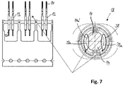
Fig. 5 . - Fig. 7
- contact zones of a female multi GHz differential pair connector;
- Fig. 8
- process steps for manufacturing signal contacts having stamped and rolled pins;
- Fig. 9A
- a detailed view of signal contacts having stamped and rolled pins manufactured in accordance with the process depicted in
Fig. 8 ; - Fig. 9B
- a sectional view of the stamped and rolled pins along section A-A of
Fig. 9B ; - Fig. 9C
- a detailed view of the signal contacts of
Fig. 9A being covered by a molded part that is manufactured by overmolding sections of the signal contacts; - Fig. 9D
- a sectional view of the signal contacts along section B-B of
Fig. 9D ; - Fig. 10
- process steps for manufacturing signal contacts having solid pins laserwelded to the remaining signal contacts;
- Fig 11A
- a perspective view of female signal contacts having stamped and rolled female signal contact portions;
- Fig. 11B
- the female signal contacts of
Fig. 11A being mechanically connected to each other by a molded part that is manufactured by overmolding sections of the signal contacts; - Fig. 11C
- the female signal contacts of
Fig. 11B aligned with corresponding male contacts; - Fig. 12A
- a perspective view of female signal contacts having stamped and twisted female signal contact portions;
- Fig. 12B
- the female signal contacts of
Fig. 12A being mechanically connected to each other by a molded part that is manufactured by overmolding the twisted sections of the signal contacts; - Fig. 12C
- the female signal contacts of
Fig. 12B aligned with corresponding male contacts; - Fig.13A
- a perspective view of female signal contacts having stamped, but non-twisted female signal contact portions;
- Fig. 13B
- the female signal contacts of
Fig. 13A being mechanically connected to each other by a molded part that is manufactured by overmolding sections of the signal contacts; and - Fig. 13C
- the female signal contacts of
Fig. 13B aligned with corresponding male contacts. -
Fig. 1A depicts an exploded view of a male multi GHzdifferential pair connector 10. The male multi GHzdifferential pair connector 10 comprises twosignal contacts 12. Each of the twosignal contacts 12 has an elongatedpin 14 extending in amating direction 16 configured to be connected to a corresponding signal contact of a female multi GHz differential pair connector 18 (seeFig. 2A ). The twosignal contacts 12 are surrounded in a first section by a first moldedpart 20 and in a second section by a second moldedpart 40 that are manufactured by overmolding the respective sections of thesignal contacts 12. The first section and the second section of each of the twosignal contacts 12 are arranged perpendicular to each other. Theovermolded signal contacts 12 are enclosed by ahousing 22 having afront part 22a and arear part 22b that are mechanically interconnected to form thehousing 22. Thehousing 22 functions as a shield for thesignal contacts 12 and an outer contact of themale connector 10. Thehousing 22 can be made out of tin-plated die-casted Zinc alloys such asZamac 3 or Zamac 5. Thesignal contacts 12 are held in position relative to thehousing 22 by the moldedparts housing 22 in a form-fitting manner. In particular, thefront part 22a of thehousing 22 forms positioning surfaces that are in contact with positioning surfaces of the moldedpart 20 to hold thesignal contacts 12 in position. The signal contacts 12 - however - are not directly in physical contact with thehousing 22. - Furthermore, the
male connector 10 comprises a connectingpart 24 that is mechanically connected to thefront part 22a and that forms amechanical fastening structure 24a to mechanically connect themale connector 10 to a female multi GHz differential pair connector via a snap-lock connection. In order to make sure that the male andfemale connectors part 24 has apassage 26 with a non-circular opening 26a that allows connecting themale connector 10 to afemale connector 18 only in one particular angular alignment. - The
front part 22a of thehousing 22 has atubular section 28 that - as can be best seen inFig. 3C in connection withFig. 4B - radially encloses the elongated pins 14. Thetubular section 28 is radially enclosed by the connectingpart 24. - As can be seen in
Fig. 4B , thesignal contacts 12 have a twistedsection 12a. Thetwisted section 12a extends in the same direction as theelongated pins 14, i.e. themating direction 16. Thetwisted sections 12a are covered by the moldedpart 20. - The manufacturing process for forming
signal contacts 12 having atwisted section 12a is now explained in conjunction withFigs. 5 and6 . First, thesignal contacts 12 including the elongated pins 14 are coined out of sheet metal. Usually, if theelongated pins 14 are manufactured by coining, side surfaces 14a of theelongated pins 14 do not contact ideally to the corresponding surfaces of a female H-MTD® connector 18. In order to improve connectivity, as can be seen in the middle ofFig. 5 , thesignal contacts 12 are being twisted by approximately 90° so that the bottom surface of the coinedelongated pin 14 becomes aside surface 14a' of theelongated pin 14, one of the side surfaces 14a of theelongated pin 14 becomes the top surface, the top surface of theelongated pin 14 becomes one of the side surfaces 14a', and the other one of theside surfaces 14a becomes the bottom surface of theelongated pin 14. A process how to manufacture such atwisted section 12a is shown inFig. 6 . - In a first step, a
first tool 30, e.g. a twist tube, is brought into a form-fitting engagement with a firstrectangular portion 32 of thesignal contact 12 and asecond tool 34, i.e. a tool to hold a secondrectangular portion 36 of thesignal contact 12, is brought into a form-fitting engagement with said secondrectangular portion 36. In a second step, thefirst tool 30, the twist tube, is rotated around its main axis by at least and/or approximately 90° rotating the firstrectangular portion 32 of thesignal contact 12 by at least and/or approximately 90° while thesecond tool 34 holds the secondrectangular portion 36 in its original position. In step three, the twisting of thetwisted section 12a is completed. In step four, thetools rectangular portions signal contact 12, the former top and bottom surfaces of thepins 14 become the side surfaces 14a' that contact the respective surfaces of the female H-MTD® connector better than the side surfaces 14a of the elongated pins ofnon-twisted signal contacts 12. - In
Fig. 7 , it is more clearly shown why the connection is improved by twisting thesignal contacts 12. On the right side ofFig. 7 , contact areas between theelongated pins 14 andsignal contacts 38 of the female H-MTD® connector are marked by ovals. These contact areas are located between inner side surfaces 38a of thesignal contacts 38 of thefemale connector 18 and, if thesignal contacts 12 of themale connector 10 are twisted, theouter side surfaces 14a' which are not damaged by the coining (seeFig. 5 , left side) of the elongated pins 14. - After the
twisted section 12a is formed, sections of thesignal contacts 12 are being overmolded (seeFig. 5 , right side) to form the moldedparts 20 in a front section of thesignal contacts 12 and moldedparts 40 in a rear section 12b of thesignal contacts 12. In order to do so, thesignal contacts 12 are placed in a mold (not shown) and then liquid plastic material is put into the mold to form the moldedparts signal contacts 12 can still be mechanically linked to each other when they are overmolded in order to keep their precise relative orientation during the molding process. - According to a second embodiment shown in
Figs. 8 and9 , thesignal contacts 12 have stamped and rolled male pins 114. As can be seen on the left side ofFig. 8 , parts are stamped out of a thin flat sheet metal. Next, as can be seen in the middle ofFig. 8 , thepins 114 are formed by rolling the parts of thin sheet metal to form two semi-circular sections with the radial end edges abutting each other to formpins 114 having a circular cross-section. Afterwards, as can be seen on the right side ofFig. 8 , thesignal contacts 12 having stamped and rolledpins 114 are over-molded like the coined andtwisted signal contacts 12 shown inFig. 5 . In this embodiment, generally, mold could flow into the stamped and rolledmale pins 114 since they are hollow. However, if thehollow pins 114 are filled with mold, efficiency of the connector is decreased. In order to avoid mold flowing into the hollow stamped and rolledmale pins 114, aproximal portion 114a of the stamped and rolledmale pins 114 is formed so that the radial end edges extend into a middle section of thepins 114 to form abarrier 115 to stop mold from flowing into thepins 114. - According to a third embodiment shown in
Fig. 10 , thesignal contacts 12 havesolid pins 214 being laser-welded to the remainingsignal contacts 12. As can be best seen in the sectional view ofFig. 10 , a holdingsection 42 having a semi-circular cross-section is formed by bending a thin sheet metal part of eachsignal contact 12. Afterwards, one of thesolid pins 214 is placed into each of thesemi-circular holding sections 42. Then, the holdingsections 42 are deformed further so that each of the holdingsections 42 encloses itsrespective pin 214 by more than 180° around the circumference of thepin 214. Next, radial ends of the holdingsections 42 are laser-welded to thesolid pins 214 to establish a material connection between each holdingsection 42 and its respectivesolid pin 214 by aweld 44. After the welding step, the section of thesignal contacts 12 forming the mechanical connection between thesolid pins 214 and therespective holding sections 42 is overmolded, as is described earlier in conjunction with the embodiment ofFig. 5 . Therefore, the moldedpart 20 covers the section of thesignal contacts 12 where thesolid pins 214 and therespective holding sections 42 are welded together. -
Figs. 11A to 13C depict different embodiments offemale signal contacts 512 which are part of a female connector (not fully shown).Fig. 11A depicts twofemale signal contacts 512 each having a femalesignal contact portion 514 which is manufactured by stamping and rolling sheet metal to form cylinder shaped femalesignal contact portions 514. The femalesignal contact portions 514 are arranged at a respective distal end of thefemale signal contacts 512. The twofemale signal contacts 512 further have a crimpingportion 515 that is configured to crimp the respectivefemale signal contact 512 to a signal wire. InFig. 11B , a further manufacturing stage of the female connector is shown. Here, the femalesignal contact portions 514 are overmolded in a section to form a moldedpart 520. The moldedpart 520 can have one or more of the properties described regarding the moldedpart 20. In particular, the moldedpart 520 holds the twofemale signal contacts 512 positioned precisely relative, e.g. parallel, to each other, even under abuse forces.Fig. 11C depicts how the femalesignal contact portions 514 having overmolded sections are connected to respective male signal contacts also having overmolded sections, e.g. like themale connector 10 ofFigs. 1 to 10 . -
Fig. 12A depicts another embodiment of two female signal contacts 612. The two female signal contacts 612 each have a femalesignal contact portion 614 which is manufactured by stamping and twisting. In order to form atwisted section 612a easily, a non-round, in particular rectangular,section 632 is formed at a distal end of thetwisted section 612a. Thetwisted section 612a is non-round. The femalesignal contact portions 614 comprise a tune fork-likeshaped section 614a to connect each female signal contact 612 to a corresponding male contact. In other words, the femalesignal contact portions 614 each form two approximately longitudinally extendingsegments 615, a connectingsegment 617 connecting the two longitudinally extending segments at their respective proximal ends and a further longitudinally extendingsegment 619 extending from the connecting segment in a proximal direction. The two approximately longitudinally extendingsegments 615 are elastically deformable and cantilevered. Furthermore, a distance between the two approximately longitudinally extendingsegments 615 is in sections smaller than a respective thickness of a corresponding male pin so that the pin can be clamped between the two elastically deformable longitudinally extendingsegments 615. - As can be seen from
Fig. 12B , in a further production step thetwisted sections 612a of the two female signal contacts 612 are overmolded to form a moldedpart 620. The molded part 620 - like theovermolded part 520 ofFig. 11B - can have one or more of the properties described regarding the moldedpart 20. In particular, the moldedpart 620 holds the two female signal contacts 612 positioned precisely relative, e.g. parallel, to each other, even under abuse forces.Fig. 12C depicts how the femalesignal contact portions 614 having overmolded twistedsections 612a are connected to respective male signal contacts also having over-molded sections, e.g. like the male connector ofFigs. 1 to 10 . -
Fig. 13A to 13C depict a further embodiment of twofemale signal contacts 712 for a female connector (not shown). In contrast to the female signal contacts 612 shown inFig. 12A , the twofemale signal contacts 712 do not have a twistedsection 612a. Instead, the twofemale signal contacts 712form plane sections 712a. As can be seen inFig. 13B , theplane sections 712a are overmolded to form a molded part 720. Another difference between the embodiments shown inFigs. 12A to 12C andFigs. 13A to 13c is the orientation of the tune fork-like shapedsections sections 614a formside openings 621 facing each other, which results in the tune fork-like shapedsections 614a contacting the respective male pins in an upper and lower region, the tune fork-like shapedsections 714a formopenings 721 that face in the same direction, which results in the tune fork-like shapedsections 714a contacting the respective male pins of a male connector in side regions of the pins. -
- 10
- male connector
- 12
- signal contact
- 12a, 612a
- twisted section
- 12b
- rear end region
- 14, 114, 214
- elongated pin
- 14a
- side surface
- 16
- mating direction
- 18
- female connector
- 20-720
- molded part
- 22
- housing
- 24
- connecting part
- 24a
- mechanical fastening structure
- 26
- passage
- 26a
- opening
- 28
- tubular section
- 30
- first tool
- 32, 632
- first rectangular section
- 34
- second tool
- 36, 636
- second rectangular section
- 38
- signal contact
- 40
- molded part
- 42
- holding section
- 44
- weld
- 114a
- proximal portion
- 115
- barrier
- 512, 612, 712
- female signal contact
- 514
- female signal contact portion
- 515
- crimping portion
- 614a, 714a
- tune fork-like shaped section
- 615
- longitudinally extending segment
- 617
- connecting segment
- 619
- longitudinally extending segment
- 621,721
- opening
Claims (15)
- Male or female connector (10) for automotive applications with
at least one signal contact (12; 512) having an elongated male pin (14) or an elongated female signal contact portion (514);
wherein a section of the signal contact (12; 512) is covered by a molded part (20, 40; 520) that is manufactured by overmolding the section of the signal contact (12; 512). - Male or female connector (10) for automotive applications according to claim 1,
wherein the signal contact (12; 612) comprises a twisted section (12a; 612a). - Male or female connector (10) for automotive applications according to claim 2,
wherein the signal contact (12; 612) has at least one non-circular cross-section (32, 36; 632) adjacent to the twisted section (12a; 612a). - Male or female connector (10) for automotive applications according to claim 3,
wherein the signal contact (12) has two non-circular cross-sections (32, 36), wherein the two non-circular cross-sections (32, 36) are arranged on opposite sides of and adjacent to the twisted section (12a). - Male or female connector (10) for automotive applications according to any one of the preceding claims,
comprising at least two signal contacts (12; 512) arranged in parallel to one another, wherein the molded part (20, 40; 520) covers a section of both signal contacts (12; 512) and the molded part (20, 40; 520) is manufactured by simultaneously overmolding the two signal contacts (12) in said section. - Male or female connector (10) for automotive applications according to claim 5,
wherein the at least two signal contacts (12; 612) each comprise a twisted section (12a; 612a). - Male or female connector (10) for automotive applications according to any one of claims 2 to 6,
wherein the at least one twisted section (12a; 612a) is covered by the molded part (20; 620). - Male or female connector (10) for automotive applications according to any one of the preceding claims,
wherein the at least one signal contact (12) forms a rear end region (12b) being arranged perpendicular to the at least one elongated pin (14). - Male or female connector (10) for automotive applications according to any one of the preceding claims,
wherein the at least one elongated male pin (14) is a coined pin
or
wherein the at least one female signal contact portion (514) is a stamped or coined female signal contact portion (514), preferably crimped to a wire. - Male or female connector (10) for automotive applications according to any one of the preceding claims,
wherein the at least one elongated male pin (14) is a stamped and rolled male pin (114)
or wherein the at least one elongated female signal contact portion (514) is a stamped and rolled female signal contact portion (514), preferably a cylindrical stamped and rolled female signal contact portion (514),
preferably wherein a barrier (115) is formed at a proximal end (114a) of the at least one elongated male pin (14) or the at least one elongated female signal contact portion (514) to block flow of liquid mold into the at least one elongated male pin (14) or the at least one elongated female signal contact portion (514) during the overmolding of the section of the signal contact (12; 512). - Male or female connector (10) for automotive applications according to any one of the preceding claims,
wherein the at least one elongated male pin (14) is a solid pin (214) welded or soldered to the signal contact (12) or
wherein the at least one elongated female signal contact portion (614; 714) has a tuning fork-like shape. - Method for producing a male connector (10) or female connector for automotive applications; including the steps of:
providing at least one signal contact (12; 512) having an elongated male pin (14) or having an elongated female signal contact portion (514); and overmolding a section of the at least one signal contact (12; 512). - Method for producing a male connector (10) or female connector for automotive applications according to claim 12,
wherein the signal contact (12; 612) is twisted in a section to form a twisted section (12a; 612a), preferably by a tool (30) that engages with at least one non-circular section (32, 36; 632) of the signal contact (12; 612) and that is then rotated along a main axis of the signal contact (12; 612). - Method for producing a male connector (10) or female connector for automotive applications according to claim 13,
wherein the twisted section (12a; 612a) is overmolded. - Method for producing a male connector (10) or female connector for automotive applications according to any one of claims 12 to 14,
wherein the at least one elongated male pin (14) is formed by one of- coining,- stamping and rolling, and- a solid pin (214) orwherein the at least one elongated female signal contact portion (514; 614; 714) is formed by one of coining, stamping without rolling, and stamping and rolling.
Priority Applications (3)
| Application Number | Priority Date | Filing Date | Title |
|---|---|---|---|
| EP21168031.9A EP4075610A1 (en) | 2021-04-13 | 2021-04-13 | Male or female connector for automotive applications and method of assembling thereof |
| CN202210384101.8A CN115207662A (en) | 2021-04-13 | 2022-04-13 | Male or female connector for automotive applications and method of assembling same |
| US17/719,739 US20220328998A1 (en) | 2021-04-13 | 2022-04-13 | Electrical connector for automotive applications and method of assembling thereof |
Applications Claiming Priority (1)
| Application Number | Priority Date | Filing Date | Title |
|---|---|---|---|
| EP21168031.9A EP4075610A1 (en) | 2021-04-13 | 2021-04-13 | Male or female connector for automotive applications and method of assembling thereof |
Publications (1)
| Publication Number | Publication Date |
|---|---|
| EP4075610A1 true EP4075610A1 (en) | 2022-10-19 |
Family
ID=75497844
Family Applications (1)
| Application Number | Title | Priority Date | Filing Date |
|---|---|---|---|
| EP21168031.9A Pending EP4075610A1 (en) | 2021-04-13 | 2021-04-13 | Male or female connector for automotive applications and method of assembling thereof |
Country Status (3)
| Country | Link |
|---|---|
| US (1) | US20220328998A1 (en) |
| EP (1) | EP4075610A1 (en) |
| CN (1) | CN115207662A (en) |
Families Citing this family (1)
| Publication number | Priority date | Publication date | Assignee | Title |
|---|---|---|---|---|
| USD1012284S1 (en) * | 2022-02-09 | 2024-01-23 | Boston Scientific Scimed, Inc. | Medical device system and removable connectors set |
Citations (3)
| Publication number | Priority date | Publication date | Assignee | Title |
|---|---|---|---|---|
| EP1786074A1 (en) * | 2005-11-10 | 2007-05-16 | Tyco Electronics France SAS | Header for electrical appartus, method for the manufacture thereof and electrical appartus. |
| US7744380B2 (en) * | 2007-02-21 | 2010-06-29 | Fci Americas Technology, Inc | Overmolded electrical contact array |
| US20150004813A1 (en) * | 2013-06-28 | 2015-01-01 | Joshua D. Heppner | Shielded sockets for microprocessors and fabrication thereof by overmolding and plating |
Family Cites Families (9)
| Publication number | Priority date | Publication date | Assignee | Title |
|---|---|---|---|---|
| DE3237159C1 (en) * | 1982-10-07 | 1984-03-01 | Harting Elektronik Gmbh, 4992 Espelkamp | Contact element for electrical plug connections and method for producing such contact elements |
| US5399110A (en) * | 1994-02-04 | 1995-03-21 | General Motors Corporation | Two piece male pin terminal |
| US20040043674A1 (en) * | 2002-08-28 | 2004-03-04 | Dunne Denise E. | DSX jack including contact |
| JP4897626B2 (en) * | 2007-09-18 | 2012-03-14 | ホシデン株式会社 | connector |
| US8506336B2 (en) * | 2011-09-02 | 2013-08-13 | Tyco Electronics Corporation | Stamped and formed contact |
| US20150222037A1 (en) * | 2014-01-31 | 2015-08-06 | Miraco, Inc. | High reliability interconnect for conductive ink circuits |
| US9991650B2 (en) * | 2016-01-22 | 2018-06-05 | Te Connectivity Corporation | Connector assembly |
| US10998657B2 (en) * | 2016-03-18 | 2021-05-04 | Apple Inc. | Precious-metal-alloy contacts |
| US10431920B1 (en) * | 2018-04-17 | 2019-10-01 | John O. Tate | One-piece parallel multi-finger contact |
-
2021
- 2021-04-13 EP EP21168031.9A patent/EP4075610A1/en active Pending
-
2022
- 2022-04-13 US US17/719,739 patent/US20220328998A1/en active Pending
- 2022-04-13 CN CN202210384101.8A patent/CN115207662A/en active Pending
Patent Citations (3)
| Publication number | Priority date | Publication date | Assignee | Title |
|---|---|---|---|---|
| EP1786074A1 (en) * | 2005-11-10 | 2007-05-16 | Tyco Electronics France SAS | Header for electrical appartus, method for the manufacture thereof and electrical appartus. |
| US7744380B2 (en) * | 2007-02-21 | 2010-06-29 | Fci Americas Technology, Inc | Overmolded electrical contact array |
| US20150004813A1 (en) * | 2013-06-28 | 2015-01-01 | Joshua D. Heppner | Shielded sockets for microprocessors and fabrication thereof by overmolding and plating |
Also Published As
| Publication number | Publication date |
|---|---|
| US20220328998A1 (en) | 2022-10-13 |
| CN115207662A (en) | 2022-10-18 |
Similar Documents
| Publication | Publication Date | Title |
|---|---|---|
| US8182285B2 (en) | Elbow coaxial electric connector and method to assemble such a connector | |
| US7607944B2 (en) | Multi-pole coaxial connector | |
| EP0105766B1 (en) | Socket contact for electrical connector and method of manufacture | |
| CN112490735B (en) | Connector and assembly for automotive applications | |
| CN112436342B (en) | Assembly comprising a connector and a cable | |
| EP2037535A2 (en) | Terminal with integral strain relief | |
| US4031614A (en) | Method of making two-piece electrical contact | |
| CN112421310A (en) | Connector for automotive applications and method of assembling same | |
| EP3783751A1 (en) | Connector for automotive applications | |
| CN104466538A (en) | Electrical connector | |
| EP4075610A1 (en) | Male or female connector for automotive applications and method of assembling thereof | |
| EP3783754A1 (en) | Connector for automotive applications | |
| EP3518353A1 (en) | Method for producing a modularly configurable coaxial plug | |
| US8272901B2 (en) | Crimp contacts and electrical connector assemblies including the same | |
| WO2007009487A1 (en) | Male electrical terminal | |
| US6428355B1 (en) | Coaxial cable assembly | |
| US6017253A (en) | Electrical connector with a tubular contact formed from an array of V-shaped members | |
| US20100304608A1 (en) | Angled Coaxial Junction | |
| EP1685625B1 (en) | Surface mount header assembly | |
| US6969272B2 (en) | Pressure welding connecting terminal and pressure welding connector receiving the same | |
| JPH09120870A (en) | Coaxial cable connector and its manufacture | |
| US6106326A (en) | Electrical connector with contact retaining module formed from reverse alternating modular frame pieces | |
| AU2020203411A1 (en) | Electrical connector and method of asssembly | |
| JP5561970B2 (en) | Connector for coaxial cable | |
| US20240313488A1 (en) | Multi-piece coaxial plug connector with variably configurable interface geometry |
Legal Events
| Date | Code | Title | Description |
|---|---|---|---|
| PUAI | Public reference made under article 153(3) epc to a published international application that has entered the european phase |
Free format text: ORIGINAL CODE: 0009012 |
|
| STAA | Information on the status of an ep patent application or granted ep patent |
Free format text: STATUS: THE APPLICATION HAS BEEN PUBLISHED |
|
| AK | Designated contracting states |
Kind code of ref document: A1 Designated state(s): AL AT BE BG CH CY CZ DE DK EE ES FI FR GB GR HR HU IE IS IT LI LT LU LV MC MK MT NL NO PL PT RO RS SE SI SK SM TR |
|
| RAP3 | Party data changed (applicant data changed or rights of an application transferred) |
Owner name: APTIV TECHNOLOGIES LIMITED |
|
| STAA | Information on the status of an ep patent application or granted ep patent |
Free format text: STATUS: REQUEST FOR EXAMINATION WAS MADE |
|
| 17P | Request for examination filed |
Effective date: 20230418 |
|
| RBV | Designated contracting states (corrected) |
Designated state(s): AL AT BE BG CH CY CZ DE DK EE ES FI FR GB GR HR HU IE IS IT LI LT LU LV MC MK MT NL NO PL PT RO RS SE SI SK SM TR |
|
| RAP1 | Party data changed (applicant data changed or rights of an application transferred) |
Owner name: APTIV TECHNOLOGIES AG |