EP4075463A1 - Operating mechanism - Google Patents
Operating mechanism Download PDFInfo
- Publication number
- EP4075463A1 EP4075463A1 EP22168576.1A EP22168576A EP4075463A1 EP 4075463 A1 EP4075463 A1 EP 4075463A1 EP 22168576 A EP22168576 A EP 22168576A EP 4075463 A1 EP4075463 A1 EP 4075463A1
- Authority
- EP
- European Patent Office
- Prior art keywords
- contact
- shaft
- hinging
- cam
- link
- Prior art date
- Legal status (The legal status is an assumption and is not a legal conclusion. Google has not performed a legal analysis and makes no representation as to the accuracy of the status listed.)
- Granted
Links
Images


Classifications
-
- H—ELECTRICITY
- H01—ELECTRIC ELEMENTS
- H01H—ELECTRIC SWITCHES; RELAYS; SELECTORS; EMERGENCY PROTECTIVE DEVICES
- H01H5/00—Snap-action arrangements, i.e. in which during a single opening operation or a single closing operation energy is first stored and then released to produce or assist the contact movement
- H01H5/04—Energy stored by deformation of elastic members
- H01H5/06—Energy stored by deformation of elastic members by compression or extension of coil springs
- H01H5/10—Energy stored by deformation of elastic members by compression or extension of coil springs one end of spring being fixedly connected to the stationary or movable part of the switch and the other end reacting with a movable or stationary rigid member respectively through pins, cams, toothed or other shaped surfaces
-
- H—ELECTRICITY
- H01—ELECTRIC ELEMENTS
- H01H—ELECTRIC SWITCHES; RELAYS; SELECTORS; EMERGENCY PROTECTIVE DEVICES
- H01H3/00—Mechanisms for operating contacts
- H01H3/22—Power arrangements internal to the switch for operating the driving mechanism
- H01H3/30—Power arrangements internal to the switch for operating the driving mechanism using spring motor
- H01H3/3031—Means for locking the spring in a charged state
-
- H—ELECTRICITY
- H01—ELECTRIC ELEMENTS
- H01H—ELECTRIC SWITCHES; RELAYS; SELECTORS; EMERGENCY PROTECTIVE DEVICES
- H01H19/00—Switches operated by an operating part which is rotatable about a longitudinal axis thereof and which is acted upon directly by a solid body external to the switch, e.g. by a hand
- H01H19/54—Switches operated by an operating part which is rotatable about a longitudinal axis thereof and which is acted upon directly by a solid body external to the switch, e.g. by a hand the operating part having at least five or an unspecified number of operative positions
- H01H19/60—Angularly-movable actuating part carrying no contacts
- H01H19/62—Contacts actuated by radial cams
- H01H19/626—Contacts actuated by radial cams actuating bridging contacts
-
- H—ELECTRICITY
- H01—ELECTRIC ELEMENTS
- H01H—ELECTRIC SWITCHES; RELAYS; SELECTORS; EMERGENCY PROTECTIVE DEVICES
- H01H3/00—Mechanisms for operating contacts
- H01H3/22—Power arrangements internal to the switch for operating the driving mechanism
- H01H3/30—Power arrangements internal to the switch for operating the driving mechanism using spring motor
-
- H—ELECTRICITY
- H01—ELECTRIC ELEMENTS
- H01H—ELECTRIC SWITCHES; RELAYS; SELECTORS; EMERGENCY PROTECTIVE DEVICES
- H01H3/00—Mechanisms for operating contacts
- H01H3/22—Power arrangements internal to the switch for operating the driving mechanism
- H01H3/30—Power arrangements internal to the switch for operating the driving mechanism using spring motor
- H01H3/3005—Charging means
- H01H3/3015—Charging means using cam devices
-
- H—ELECTRICITY
- H01—ELECTRIC ELEMENTS
- H01H—ELECTRIC SWITCHES; RELAYS; SELECTORS; EMERGENCY PROTECTIVE DEVICES
- H01H3/00—Mechanisms for operating contacts
- H01H3/32—Driving mechanisms, i.e. for transmitting driving force to the contacts
- H01H3/42—Driving mechanisms, i.e. for transmitting driving force to the contacts using cam or eccentric
-
- H—ELECTRICITY
- H01—ELECTRIC ELEMENTS
- H01H—ELECTRIC SWITCHES; RELAYS; SELECTORS; EMERGENCY PROTECTIVE DEVICES
- H01H3/00—Mechanisms for operating contacts
- H01H3/22—Power arrangements internal to the switch for operating the driving mechanism
- H01H3/30—Power arrangements internal to the switch for operating the driving mechanism using spring motor
- H01H3/3031—Means for locking the spring in a charged state
- H01H2003/3036—Means for locking the spring in a charged state using of balls or rollers in the locking device
-
- H—ELECTRICITY
- H01—ELECTRIC ELEMENTS
- H01H—ELECTRIC SWITCHES; RELAYS; SELECTORS; EMERGENCY PROTECTIVE DEVICES
- H01H71/00—Details of the protective switches or relays covered by groups H01H73/00 - H01H83/00
- H01H71/10—Operating or release mechanisms
Definitions
- the invention relates to an operating mechanism for opening and closing at least one contact, which operating mechanism comprises:
- a spring could also be arranged to the cam, wherein the spring is energized at a certain level and then released to complete the closing operation.
- the spring is used for achieving the right speed and contact force. If the cam is used to keep the rod mechanism in closed position, the spring cannot be reenergized until the cam is rotated to open the contact.
- the D-shaft portion in combination with the locking lever provides a lock for the rod mechanism, such that the contact can be kept in closed position, while the cam can be rotated further.
- the D-shaft portion only has to be rotated to release the rod mechanism.
- the cam can be rotated further, while the contact is maintained in the closed position, a spring provided to assist in the closing movement, can already be reenergized directly after the closing movement is completed.
- a first spring is arranged to the control shaft to urge the control shaft in the lock position.
- a roller is arranged on the locking lever, wherein the roller forms the second end of the locking lever.
- the roller reduces any friction with the D-shaft portion and improves the urging by the locking lever of the D-shaft portion in the pass position.
- a cam follower is arranged on the hinging axis of the first ends of the first and second links and wherein the cam follower is configured to be in contact with the cam.
- the cam follower reduces friction and wear between the cam and the rod mechanism.
- the profile of the cam has a closing profile section for urging the rod mechanism in a stretched position, an opening profile section for letting the rod mechanism fold and an idle profile section, further comprising a closing spring for urging the closing profile section of the cam in contact with the hinging axis of the first ends of the two links.
- Figure 1 shows a perspective view of a part of an embodiment of an operating mechanism according to the invention.
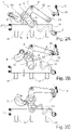
- Figures 2A - 2C show the embodiment of figure 1 in schematical view.
- Figures 3A and 3B show a detail of the D-shaft portion in the pass position and the lock position respectively.
- Figure 1 shows an operating mechanism 1 for opening and closing a contact.
- the operating mechanism 1 has a base frame (not shown) and a bridge body 3 with which operating rods of contacts can be operated.
- a cam follower 6 is provided at this hinge axis.
- the first link 4 is hinged with the other end 7 to the base frame and the second link 5 is hinged with the other end 8 to the bridge body 3.
- a camshaft 9 with a cam 10 is provided in operating contact with the cam follower 6 to urge the rod mechanism 4, 5 in a stretched position in which the contacts are closed and a collapsed position in which the contacts are opened.
- a closing spring 11 is connected to the camshaft 9 to assist in the closing movement.
- a locking lever 12 is fixedly arranged to the first link 4 and provided with a roller 13 on the free end of the locking lever 12.
- a control shaft 14 with a D-shaft portion 15 is provided adjacent the roller 13, to lock the locking lever 12 when the rod mechanism 4, 5 is stretched and the contacts are closed.
- FIG 2A shows the operating mechanism 1 as shown in figure 1 in more schematic view.
- the bridge body 3 is in a raised position, such that contacts 17 arranged against the contact surface 18 of the bridge body 3 are in an open position.
- the rod mechanism 4, 5 is collapsed position and the locking lever 12 is rotated away from the D-shaft portion 15, which is urged by a spring 16.
- Figure 2C shows the position of the bridge body 3 in closed position, in which the contacts 17 are also closed.
- the locking lever 12 with roller 13 has passed the D-shaft portion 15, which is rotated by the spring 16 in the lock position, which prevents the rod mechanism 4, 5 to return to the position of figure 2A .
- Figure 3A shows the D-shaft portion 15.
- the cross-section has a circumference with a straight portion 20 and a semi cylindrical portion 21.
- the path 19 of the locking lever 12 is positioned outside of the cross-section of the D-shaft portion 15.
- Figure 3A shows the D-shaft portion 15 in the lock position, where the path 19 intersects with the cross-section of the D-shaft portion 15.
Landscapes
- Mechanisms For Operating Contacts (AREA)
- Driving Mechanisms And Operating Circuits Of Arc-Extinguishing High-Tension Switches (AREA)
- Mechanical Control Devices (AREA)
- Specific Sealing Or Ventilating Devices For Doors And Windows (AREA)
- Operating, Guiding And Securing Of Roll- Type Closing Members (AREA)
Abstract
- a base frame;
- a bridge body movable relative to the base frame between a closed position and an opened position, wherein the bridge body has a contact surface with a length and a width, which contact surface is configured to extend in length direction over and be in contact with the operating rod of the at least one contact;
- a rod mechanism of a first and a second link wherein the first ends of the two links are hinging with each other, wherein the second end of first link is hinging with the base frame and the second end of the second link is hinging with the bridging body;
- a cam arranged on a shaft, wherein the shaft is arranged adjacent to the rod mechanism, wherein the shaft extends parallel to the hinging axes of the rod mechanism and wherein the cam is in operating contact with the hinging axis of the first ends of the two links;
- a locking lever fixedly arranged with one end to the first link and moves with the first rod between a locked position and an unlocked position;
- a control shaft having a D-shaft portion with a flat surface portion and a semi cylindrical surface portion;
wherein the D-shaft portion can be rotated between a pass position, in which the path of the second end of the locking lever is positioned outside of the circumference of the cross-section of the D-shaft portion, and a lock position, in which the path of the second end of the locking lever intersects with the circumference of the cross-section of the D-shaft portion.
Description
- The invention relates to an operating mechanism for opening and closing at least one contact, which operating mechanism comprises:
- a base frame;
- a bridge body movable relative to the base frame between a closed position and an opened position, wherein the bridge body has a contact surface with a length and a width, which contact surface is configured to extend in length direction over and be in contact with the operating rod of the at least one contact;
- a rod mechanism of a first and a second link wherein the first ends of the two links are hinging with each other, wherein the second end of first link is hinging with the base frame and the second end of the second link is hinging with the bridging body;
- a cam arranged on a shaft, wherein the shaft is arranged adjacent to the rod mechanism, wherein the shaft extends parallel to the hinging axes of the rod mechanism and wherein the cam is in operating contact with the hinging axis of the first ends of the two links.
- In larger (medium voltage) mechanical operated switchgear generally closing of the contact is achieved by the cam operating on the rod mechanism. The opening of the contact typically needs to be quick. This can be done by shaping the cam profile such, that with a minimal rotation of the cam from the closed position, the operating mechanism is release and free to move to the open position without intervention of the cam.
- However in mechanical operated switchgear a spring could also be arranged to the cam, wherein the spring is energized at a certain level and then released to complete the closing operation. The spring is used for achieving the right speed and contact force. If the cam is used to keep the rod mechanism in closed position, the spring cannot be reenergized until the cam is rotated to open the contact.
- It is an object of the invention to reduce or even remove the above mentioned disadvantages.
- This object is achieved according to the invention with an operating mechanism according to the preamble, which is characterized by:
- a locking lever fixedly arranged with one end to the first link and moves with the first link between a locked position and an unlocked position;
- a control shaft having a D-shaft portion with a flat surface portion and a semi cylindrical surface portion;
- The D-shaft portion in combination with the locking lever provides a lock for the rod mechanism, such that the contact can be kept in closed position, while the cam can be rotated further. When the contact needs to be opened, the D-shaft portion only has to be rotated to release the rod mechanism.
- Now the cam can be rotated further, while the contact is maintained in the closed position, a spring provided to assist in the closing movement, can already be reenergized directly after the closing movement is completed.
- In a preferred embodiment of the operating mechanism according to the invention a first spring is arranged to the control shaft to urge the control shaft in the lock position.
- This allows for the locking lever to push the D-shaft portion into the pass position, after which the first spring will urge the D-shaft portion back into the lock position, such that the rod mechanism and the contact is locked in the closed position.
- Preferably, a roller is arranged on the locking lever, wherein the roller forms the second end of the locking lever. The roller reduces any friction with the D-shaft portion and improves the urging by the locking lever of the D-shaft portion in the pass position.
- In another embodiment of the operating mechanism according to the invention a cam follower is arranged on the hinging axis of the first ends of the first and second links and wherein the cam follower is configured to be in contact with the cam.
- The cam follower reduces friction and wear between the cam and the rod mechanism.
- In yet another embodiment of the operating mechanism according to the invention, the profile of the cam has a closing profile section for urging the rod mechanism in a stretched position, an opening profile section for letting the rod mechanism fold and an idle profile section, further comprising a closing spring for urging the closing profile section of the cam in contact with the hinging axis of the first ends of the two links.
- These and other features of the invention will be elucidated in conjunction with the accompanying drawings.
-
Figure 1 shows a perspective view of a part of an embodiment of an operating mechanism according to the invention. -
Figures 2A - 2C show the embodiment offigure 1 in schematical view. -
Figures 3A and 3B show a detail of the D-shaft portion in the pass position and the lock position respectively. -
Figure 1 shows an operating mechanism 1 for opening and closing a contact. The operating mechanism 1 has a base frame (not shown) and abridge body 3 with which operating rods of contacts can be operated. - A rod mechanism of two
links cam follower 6 is provided at this hinge axis. Thefirst link 4 is hinged with theother end 7 to the base frame and thesecond link 5 is hinged with theother end 8 to thebridge body 3. - A
camshaft 9 with acam 10 is provided in operating contact with thecam follower 6 to urge therod mechanism closing spring 11 is connected to thecamshaft 9 to assist in the closing movement. - A
locking lever 12 is fixedly arranged to thefirst link 4 and provided with aroller 13 on the free end of thelocking lever 12. Acontrol shaft 14 with a D-shaft portion 15 is provided adjacent theroller 13, to lock thelocking lever 12 when therod mechanism -
Figure 2A shows the operating mechanism 1 as shown infigure 1 in more schematic view. Thebridge body 3 is in a raised position, such thatcontacts 17 arranged against thecontact surface 18 of thebridge body 3 are in an open position. Therod mechanism locking lever 12 is rotated away from the D-shaft portion 15, which is urged by aspring 16. - In
figure 2B thecam shaft 9 is rotated such that thecam 10 operates on thecam follower 6 and pushes therod mechanism bridge body 3 is moved down and thecontacts 17 are closed. This closing action is assisted by theclosing spring 11. - When the
rod mechanism locking lever 12 with theroller 13 moves along thepath 19 and arrives at the D-shaft portion 15, which is positioned in a pass position, where thelocking lever 12 withroller 13 can pass the D-shaft portion 15. -
Figure 2C shows the position of thebridge body 3 in closed position, in which thecontacts 17 are also closed. Thelocking lever 12 withroller 13 has passed the D-shaft portion 15, which is rotated by thespring 16 in the lock position, which prevents therod mechanism figure 2A . This allows for thecamshaft 9 to be rotated further in order to re-energize theclosing spring 11. -
Figure 3A shows the D-shaft portion 15. The cross-section has a circumference with astraight portion 20 and a semicylindrical portion 21. In the pass position as shown infigure 3A , thepath 19 of thelocking lever 12 is positioned outside of the cross-section of the D-shaft portion 15. -
Figure 3A shows the D-shaft portion 15 in the lock position, where thepath 19 intersects with the cross-section of the D-shaft portion 15.
Claims (5)
- Operating mechanism (1) for opening and closing at least one contact (17), which operating mechanism (1) comprises:- a base frame (2);- a bridge body (3) movable relative to the base frame (2) between a closed position and an opened position, wherein the bridge body (3) has a contact surface (18) with a length and a width, which contact surface (18) is configured to extend in length direction over and be in contact with the operating rod of the at least one contact (17);- a rod mechanism of a first (4) and a second (5) link wherein the first ends of the two links are hinging with each other, wherein the second end (7) of first link (4) is hinging with the base frame (2) and the second end (8) of the second link (5) is hinging with the bridging body (3);- a cam (10) arranged on a shaft (9), wherein the shaft (9) is arranged adjacent to the rod mechanism (4, 5), wherein the shaft (9) extends parallel to the hinging axes of the rod mechanism (4, 5) and wherein the cam (10) is in operating contact with the hinging axis of the first ends of the two links (4, 5);characterized by- a locking lever (12) fixedly arranged with one end to the first link (4) and moves with the first link (4) between a locked position and an unlocked position;- a control shaft (14) having a D-shaft portion (15) with a flat surface portion (20) and a semi cylindrical surface portion (21);wherein the D-shaft portion (15) can be rotated between a pass position, in which the path (19) of the second end (13) of the locking lever (12) is positioned outside of the circumference of the cross-section of the D-shaft portion (15), and a lock position, in which the path (19) of the second end of the locking lever (12) intersects with the circumference of the cross-section of the D-shaft portion (15) .
- Operating mechanism (1) according to claim 1, wherein a first spring (16) is arranged to the control shaft (14) to urge the control shaft (14) in the lock position.
- Operating mechanism (1) according to claim 1 or 2, wherein a roller (13) is arranged on the locking lever (12) and wherein the roller (13) forms the second end of the locking lever (12).
- Operating mechanism (1) according to any of the preceding claims, wherein a cam follower (6) is arranged on the hinging axis of the first ends of the first (4) and second (5) links and wherein the cam follower (6) is configured to be in contact with the cam (10).
- Operating mechanism (1) according to any of the preceding claims, wherein the profile of the cam (10) has a closing profile section for urging the rod mechanism (4, 5) in a stretched position, an opening profile section for letting the rod mechanism (4, 5) fold and an idle profile section, further comprising a closing spring (11) for urging the closing profile section of the cam (10) in contact with the hinging axis of the first ends of the two links (4, 5).
Applications Claiming Priority (1)
| Application Number | Priority Date | Filing Date | Title |
|---|---|---|---|
| GB2105356.6A GB2605822B (en) | 2021-04-15 | 2021-04-15 | Operating mechanism |
Publications (2)
| Publication Number | Publication Date |
|---|---|
| EP4075463A1 true EP4075463A1 (en) | 2022-10-19 |
| EP4075463B1 EP4075463B1 (en) | 2025-05-28 |
Family
ID=76377653
Family Applications (1)
| Application Number | Title | Priority Date | Filing Date |
|---|---|---|---|
| EP22168576.1A Active EP4075463B1 (en) | 2021-04-15 | 2022-04-14 | Operating mechanism |
Country Status (6)
| Country | Link |
|---|---|
| US (1) | US11955299B2 (en) |
| EP (1) | EP4075463B1 (en) |
| JP (1) | JP7329655B2 (en) |
| GB (1) | GB2605822B (en) |
| PL (1) | PL4075463T3 (en) |
| ZA (1) | ZA202204245B (en) |
Families Citing this family (2)
| Publication number | Priority date | Publication date | Assignee | Title |
|---|---|---|---|---|
| CN113867248B (en) * | 2021-09-18 | 2023-10-17 | 北京理工大学 | A multi-level interlocking circuit based on multi-level cam interlocking structure |
| CN118571722B (en) * | 2024-05-07 | 2024-11-22 | 昆山盛英电气有限公司 | A separation arc extinguishing device and low-voltage cabinet for smart grid power distribution |
Citations (4)
| Publication number | Priority date | Publication date | Assignee | Title |
|---|---|---|---|---|
| US4409449A (en) * | 1979-02-13 | 1983-10-11 | Tokyo Shibaura Denki Kabushiki Kaisha | Operating mechanism for use in a circuit breaker |
| EP0302721A2 (en) * | 1987-08-06 | 1989-02-08 | Square D Company | Switch assembly |
| CN205159204U (en) * | 2015-12-07 | 2016-04-13 | 武汉大学 | An indoor high-voltage vacuum circuit breaker spring operating mechanism |
| WO2018115026A1 (en) * | 2016-12-23 | 2018-06-28 | Eaton Industries (Austria) Gmbh | Mechanism for opening and closing a circuit breaker |
Family Cites Families (6)
| Publication number | Priority date | Publication date | Assignee | Title |
|---|---|---|---|---|
| JP3441837B2 (en) * | 1995-04-24 | 2003-09-02 | 三菱電機株式会社 | Switchgear operation mechanism |
| JP3497866B2 (en) | 1997-08-26 | 2004-02-16 | 株式会社日立製作所 | Circuit breaker |
| DE10120783C1 (en) * | 2001-04-23 | 2002-11-14 | Siemens Ag | Key switch for latching a spring mechanism |
| US7449653B2 (en) * | 2007-03-29 | 2008-11-11 | Eaton Corporation | Positive resetting close latch for closing electrical switching apparatus |
| US8063328B2 (en) * | 2009-09-16 | 2011-11-22 | Eaton Corporation | Electrical switching apparatus and charging assembly therefor |
| FR3090188B1 (en) * | 2018-12-14 | 2022-02-04 | Schneider Electric Ind Sas | Electric current cut-off device |
-
2021
- 2021-04-15 GB GB2105356.6A patent/GB2605822B/en not_active Expired - Fee Related
-
2022
- 2022-04-14 EP EP22168576.1A patent/EP4075463B1/en active Active
- 2022-04-14 PL PL22168576.1T patent/PL4075463T3/en unknown
- 2022-04-14 ZA ZA2022/04245A patent/ZA202204245B/en unknown
- 2022-04-15 US US17/659,430 patent/US11955299B2/en active Active
- 2022-04-15 JP JP2022067456A patent/JP7329655B2/en active Active
Patent Citations (4)
| Publication number | Priority date | Publication date | Assignee | Title |
|---|---|---|---|---|
| US4409449A (en) * | 1979-02-13 | 1983-10-11 | Tokyo Shibaura Denki Kabushiki Kaisha | Operating mechanism for use in a circuit breaker |
| EP0302721A2 (en) * | 1987-08-06 | 1989-02-08 | Square D Company | Switch assembly |
| CN205159204U (en) * | 2015-12-07 | 2016-04-13 | 武汉大学 | An indoor high-voltage vacuum circuit breaker spring operating mechanism |
| WO2018115026A1 (en) * | 2016-12-23 | 2018-06-28 | Eaton Industries (Austria) Gmbh | Mechanism for opening and closing a circuit breaker |
Also Published As
| Publication number | Publication date |
|---|---|
| PL4075463T3 (en) | 2025-08-04 |
| JP7329655B2 (en) | 2023-08-18 |
| GB202105356D0 (en) | 2021-06-02 |
| GB2605822B (en) | 2023-05-31 |
| GB2605822A (en) | 2022-10-19 |
| US11955299B2 (en) | 2024-04-09 |
| JP2022164630A (en) | 2022-10-27 |
| US20220336163A1 (en) | 2022-10-20 |
| EP4075463B1 (en) | 2025-05-28 |
| ZA202204245B (en) | 2024-09-25 |
Similar Documents
| Publication | Publication Date | Title |
|---|---|---|
| US20220336163A1 (en) | Operating mechanism | |
| KR100991947B1 (en) | Lock for door or lid of vehicle | |
| US6382687B1 (en) | Power-closing motor-vehicle door latch | |
| EP1205619B1 (en) | Locking controller of a sliding door | |
| DE19859565B4 (en) | Electric door closer | |
| KR20070046910A (en) | Lock for door or lid of vehicle | |
| EP1489252B1 (en) | Motor vehicle door lock | |
| US4468941A (en) | Electric locking device, particularly for an automobile hood | |
| IL201282A (en) | Door lock | |
| CN113710863B (en) | Door lock, in particular motor vehicle door lock | |
| EP3996123B1 (en) | Operating mechanism for operating at least one contact and operating method therefor | |
| DE19713864A1 (en) | Motor vehicle door lock | |
| DE10029123C2 (en) | Clamping device for a spring accumulator of a circuit breaker | |
| EP1284494B1 (en) | Latch mechanism for a circuit breaker, particularly for a protective switch for a motor | |
| CA3238976A1 (en) | Gate valve and valve actuator | |
| EP1418385B1 (en) | Door locking for baking oven | |
| DE3114727C2 (en) | ||
| EP0965717B1 (en) | Device for the quick release of gate wings | |
| JP5197031B2 (en) | Circuit breaker operation mechanism | |
| EP4075465A1 (en) | Operating mechanism for a switch | |
| US6758505B2 (en) | Locking-mechanism control means | |
| DE592875C (en) | ||
| CN121184017A (en) | Cover opening and closing device | |
| JPH10280768A (en) | Locking device | |
| DE10232095A1 (en) | Clutch system has plate-shaped levers in which are cavities and rotary axles, thrust pieces, and fixed bolts |
Legal Events
| Date | Code | Title | Description |
|---|---|---|---|
| PUAI | Public reference made under article 153(3) epc to a published international application that has entered the european phase |
Free format text: ORIGINAL CODE: 0009012 |
|
| STAA | Information on the status of an ep patent application or granted ep patent |
Free format text: STATUS: REQUEST FOR EXAMINATION WAS MADE |
|
| 17P | Request for examination filed |
Effective date: 20220414 |
|
| AK | Designated contracting states |
Kind code of ref document: A1 Designated state(s): AL AT BE BG CH CY CZ DE DK EE ES FI FR GB GR HR HU IE IS IT LI LT LU LV MC MK MT NL NO PL PT RO RS SE SI SK SM TR |
|
| P01 | Opt-out of the competence of the unified patent court (upc) registered |
Effective date: 20230521 |
|
| GRAP | Despatch of communication of intention to grant a patent |
Free format text: ORIGINAL CODE: EPIDOSNIGR1 |
|
| STAA | Information on the status of an ep patent application or granted ep patent |
Free format text: STATUS: GRANT OF PATENT IS INTENDED |
|
| RIC1 | Information provided on ipc code assigned before grant |
Ipc: H01H 71/10 20060101ALN20241028BHEP Ipc: H01H 3/30 20060101ALI20241028BHEP Ipc: H01H 5/10 20060101AFI20241028BHEP |
|
| INTG | Intention to grant announced |
Effective date: 20241107 |
|
| GRAS | Grant fee paid |
Free format text: ORIGINAL CODE: EPIDOSNIGR3 |
|
| GRAA | (expected) grant |
Free format text: ORIGINAL CODE: 0009210 |
|
| STAA | Information on the status of an ep patent application or granted ep patent |
Free format text: STATUS: THE PATENT HAS BEEN GRANTED |
|
| AK | Designated contracting states |
Kind code of ref document: B1 Designated state(s): AL AT BE BG CH CY CZ DE DK EE ES FI FR GB GR HR HU IE IS IT LI LT LU LV MC MK MT NL NO PL PT RO RS SE SI SK SM TR |
|
| REG | Reference to a national code |
Ref country code: GB Ref legal event code: FG4D |
|
| REG | Reference to a national code |
Ref country code: CH Ref legal event code: EP |
|
| REG | Reference to a national code |
Ref country code: DE Ref legal event code: R096 Ref document number: 602022015117 Country of ref document: DE |
|
| REG | Reference to a national code |
Ref country code: IE Ref legal event code: FG4D |
|
| REG | Reference to a national code |
Ref country code: SE Ref legal event code: TRGR |
|
| REG | Reference to a national code |
Ref country code: NL Ref legal event code: FP |
|
| PG25 | Lapsed in a contracting state [announced via postgrant information from national office to epo] |
Ref country code: ES Free format text: LAPSE BECAUSE OF FAILURE TO SUBMIT A TRANSLATION OF THE DESCRIPTION OR TO PAY THE FEE WITHIN THE PRESCRIBED TIME-LIMIT Effective date: 20250528 Ref country code: FI Free format text: LAPSE BECAUSE OF FAILURE TO SUBMIT A TRANSLATION OF THE DESCRIPTION OR TO PAY THE FEE WITHIN THE PRESCRIBED TIME-LIMIT Effective date: 20250528 |
|
| REG | Reference to a national code |
Ref country code: LT Ref legal event code: MG9D |
|
| PG25 | Lapsed in a contracting state [announced via postgrant information from national office to epo] |
Ref country code: NO Free format text: LAPSE BECAUSE OF FAILURE TO SUBMIT A TRANSLATION OF THE DESCRIPTION OR TO PAY THE FEE WITHIN THE PRESCRIBED TIME-LIMIT Effective date: 20250828 Ref country code: GR Free format text: LAPSE BECAUSE OF FAILURE TO SUBMIT A TRANSLATION OF THE DESCRIPTION OR TO PAY THE FEE WITHIN THE PRESCRIBED TIME-LIMIT Effective date: 20250829 |
|
| PG25 | Lapsed in a contracting state [announced via postgrant information from national office to epo] |
Ref country code: BG Free format text: LAPSE BECAUSE OF FAILURE TO SUBMIT A TRANSLATION OF THE DESCRIPTION OR TO PAY THE FEE WITHIN THE PRESCRIBED TIME-LIMIT Effective date: 20250528 |
|
| PG25 | Lapsed in a contracting state [announced via postgrant information from national office to epo] |
Ref country code: HR Free format text: LAPSE BECAUSE OF FAILURE TO SUBMIT A TRANSLATION OF THE DESCRIPTION OR TO PAY THE FEE WITHIN THE PRESCRIBED TIME-LIMIT Effective date: 20250528 |
|
| PG25 | Lapsed in a contracting state [announced via postgrant information from national office to epo] |
Ref country code: RS Free format text: LAPSE BECAUSE OF FAILURE TO SUBMIT A TRANSLATION OF THE DESCRIPTION OR TO PAY THE FEE WITHIN THE PRESCRIBED TIME-LIMIT Effective date: 20250828 |
|
| PG25 | Lapsed in a contracting state [announced via postgrant information from national office to epo] |
Ref country code: IS Free format text: LAPSE BECAUSE OF FAILURE TO SUBMIT A TRANSLATION OF THE DESCRIPTION OR TO PAY THE FEE WITHIN THE PRESCRIBED TIME-LIMIT Effective date: 20250928 |
|
| PG25 | Lapsed in a contracting state [announced via postgrant information from national office to epo] |
Ref country code: LV Free format text: LAPSE BECAUSE OF FAILURE TO SUBMIT A TRANSLATION OF THE DESCRIPTION OR TO PAY THE FEE WITHIN THE PRESCRIBED TIME-LIMIT Effective date: 20250528 |
|
| REG | Reference to a national code |
Ref country code: AT Ref legal event code: MK05 Ref document number: 1799126 Country of ref document: AT Kind code of ref document: T Effective date: 20250528 |
|
| PG25 | Lapsed in a contracting state [announced via postgrant information from national office to epo] |
Ref country code: SM Free format text: LAPSE BECAUSE OF FAILURE TO SUBMIT A TRANSLATION OF THE DESCRIPTION OR TO PAY THE FEE WITHIN THE PRESCRIBED TIME-LIMIT Effective date: 20250528 Ref country code: AT Free format text: LAPSE BECAUSE OF FAILURE TO SUBMIT A TRANSLATION OF THE DESCRIPTION OR TO PAY THE FEE WITHIN THE PRESCRIBED TIME-LIMIT Effective date: 20250528 Ref country code: DK Free format text: LAPSE BECAUSE OF FAILURE TO SUBMIT A TRANSLATION OF THE DESCRIPTION OR TO PAY THE FEE WITHIN THE PRESCRIBED TIME-LIMIT Effective date: 20250528 |
|
| PG25 | Lapsed in a contracting state [announced via postgrant information from national office to epo] |
Ref country code: CZ Free format text: LAPSE BECAUSE OF FAILURE TO SUBMIT A TRANSLATION OF THE DESCRIPTION OR TO PAY THE FEE WITHIN THE PRESCRIBED TIME-LIMIT Effective date: 20250528 |
|
| PG25 | Lapsed in a contracting state [announced via postgrant information from national office to epo] |
Ref country code: EE Free format text: LAPSE BECAUSE OF FAILURE TO SUBMIT A TRANSLATION OF THE DESCRIPTION OR TO PAY THE FEE WITHIN THE PRESCRIBED TIME-LIMIT Effective date: 20250528 |
|
| PG25 | Lapsed in a contracting state [announced via postgrant information from national office to epo] |
Ref country code: SK Free format text: LAPSE BECAUSE OF FAILURE TO SUBMIT A TRANSLATION OF THE DESCRIPTION OR TO PAY THE FEE WITHIN THE PRESCRIBED TIME-LIMIT Effective date: 20250528 |
|
| PG25 | Lapsed in a contracting state [announced via postgrant information from national office to epo] |
Ref country code: IT Free format text: LAPSE BECAUSE OF FAILURE TO SUBMIT A TRANSLATION OF THE DESCRIPTION OR TO PAY THE FEE WITHIN THE PRESCRIBED TIME-LIMIT Effective date: 20250528 |
|
| REG | Reference to a national code |
Ref country code: DE Ref legal event code: R097 Ref document number: 602022015117 Country of ref document: DE |
|
| PLBE | No opposition filed within time limit |
Free format text: ORIGINAL CODE: 0009261 |
|
| STAA | Information on the status of an ep patent application or granted ep patent |
Free format text: STATUS: NO OPPOSITION FILED WITHIN TIME LIMIT |
|
| PGFP | Annual fee paid to national office [announced via postgrant information from national office to epo] |
Ref country code: SE Payment date: 20260319 Year of fee payment: 5 |
|
| PGFP | Annual fee paid to national office [announced via postgrant information from national office to epo] |
Ref country code: GB Payment date: 20260319 Year of fee payment: 5 |
|
| REG | Reference to a national code |
Ref country code: CH Ref legal event code: L10 Free format text: ST27 STATUS EVENT CODE: U-0-0-L10-L00 (AS PROVIDED BY THE NATIONAL OFFICE) Effective date: 20260409 |
|
| PGFP | Annual fee paid to national office [announced via postgrant information from national office to epo] |
Ref country code: NL Payment date: 20260319 Year of fee payment: 5 |
|
| PGFP | Annual fee paid to national office [announced via postgrant information from national office to epo] |
Ref country code: PL Payment date: 20260319 Year of fee payment: 5 |
|
| 26N | No opposition filed |
Effective date: 20260303 |