EP4075447A1 - Nuclear fuel assembly top nozzle comprising a hold-down device - Google Patents
Nuclear fuel assembly top nozzle comprising a hold-down device Download PDFInfo
- Publication number
- EP4075447A1 EP4075447A1 EP21305504.9A EP21305504A EP4075447A1 EP 4075447 A1 EP4075447 A1 EP 4075447A1 EP 21305504 A EP21305504 A EP 21305504A EP 4075447 A1 EP4075447 A1 EP 4075447A1
- Authority
- EP
- European Patent Office
- Prior art keywords
- plate
- spring member
- top nozzle
- auxiliary spring
- intermediate plate
- Prior art date
- Legal status (The legal status is an assumption and is not a legal conclusion. Google has not performed a legal analysis and makes no representation as to the accuracy of the status listed.)
- Withdrawn
Links
- 239000003758 nuclear fuel Substances 0.000 title claims description 23
- 230000036316 preload Effects 0.000 claims abstract description 28
- 125000006850 spacer group Chemical group 0.000 claims description 13
- 239000000446 fuel Substances 0.000 description 42
- 239000002826 coolant Substances 0.000 description 9
- 230000000670 limiting effect Effects 0.000 description 4
- 230000007423 decrease Effects 0.000 description 3
- 230000004913 activation Effects 0.000 description 2
- 238000005253 cladding Methods 0.000 description 2
- 239000008188 pellet Substances 0.000 description 2
- 230000003247 decreasing effect Effects 0.000 description 1
- 230000000694 effects Effects 0.000 description 1
- 230000001747 exhibiting effect Effects 0.000 description 1
- 230000037431 insertion Effects 0.000 description 1
- 238000003780 insertion Methods 0.000 description 1
- 230000009257 reactivity Effects 0.000 description 1
- 230000002829 reductive effect Effects 0.000 description 1
- 230000000284 resting effect Effects 0.000 description 1
- 230000000717 retained effect Effects 0.000 description 1
Images


Classifications
-
- G—PHYSICS
- G21—NUCLEAR PHYSICS; NUCLEAR ENGINEERING
- G21C—NUCLEAR REACTORS
- G21C3/00—Reactor fuel elements and their assemblies; Selection of substances for use as reactor fuel elements
- G21C3/30—Assemblies of a number of fuel elements in the form of a rigid unit
- G21C3/32—Bundles of parallel pin-, rod-, or tube-shaped fuel elements
- G21C3/33—Supporting or hanging of elements in the bundle; Means forming part of the bundle for inserting it into, or removing it from, the core; Means for coupling adjacent bundles
- G21C3/331—Comprising hold-down means, e.g. springs
-
- G—PHYSICS
- G21—NUCLEAR PHYSICS; NUCLEAR ENGINEERING
- G21C—NUCLEAR REACTORS
- G21C3/00—Reactor fuel elements and their assemblies; Selection of substances for use as reactor fuel elements
- G21C3/30—Assemblies of a number of fuel elements in the form of a rigid unit
- G21C3/32—Bundles of parallel pin-, rod-, or tube-shaped fuel elements
- G21C3/33—Supporting or hanging of elements in the bundle; Means forming part of the bundle for inserting it into, or removing it from, the core; Means for coupling adjacent bundles
- G21C3/3315—Upper nozzle
-
- Y—GENERAL TAGGING OF NEW TECHNOLOGICAL DEVELOPMENTS; GENERAL TAGGING OF CROSS-SECTIONAL TECHNOLOGIES SPANNING OVER SEVERAL SECTIONS OF THE IPC; TECHNICAL SUBJECTS COVERED BY FORMER USPC CROSS-REFERENCE ART COLLECTIONS [XRACs] AND DIGESTS
- Y02—TECHNOLOGIES OR APPLICATIONS FOR MITIGATION OR ADAPTATION AGAINST CLIMATE CHANGE
- Y02E—REDUCTION OF GREENHOUSE GAS [GHG] EMISSIONS, RELATED TO ENERGY GENERATION, TRANSMISSION OR DISTRIBUTION
- Y02E30/00—Energy generation of nuclear origin
- Y02E30/30—Nuclear fission reactors
Definitions
- the present invention relates to a top nozzle for a nuclear fuel assembly.
- a nuclear fuel assembly (or “fuel assembly”) comprises nuclear fuel rods (or “fuel rods”) arranged in a bundle and a skeleton supporting the fuel rods.
- Each fuel rod comprises a tubular cladding containing nuclear fuel (e.g. nuclear fuel pellets, in particular UO 2 pellets), the two ends of the tubular cladding being closed by respective end plugs.
- nuclear fuel e.g. nuclear fuel pellets, in particular UO 2 pellets
- the skeleton comprises for example a bottom nozzle and a top nozzle spaced along an assembly axis, guide thimbles extending along the assembly axis between the bottom nozzle and the top nozzle with connecting the bottom nozzle and the top nozzle together, and spacer grids attached to the guide thimbles with being distributed along the guide thimbles, between the bottom nozzle and the top nozzle.
- the fuel rods extend between the bottom nozzle and the top nozzle with passing through the spacer grids.
- the function of the spacer grids is to support the fuel rods along the assembly axis and transversely to the assembly axis with maintaining the fuel rods in a spaced relationship.
- the fuel assembly is inserted into a reactor core received into a reactor vessel, with the longitudinal axis of the fuel assembly extending substantially vertically, and a coolant flows vertically through the fuel assembly for moderating the nuclear reaction and for retrieving heat produced by the fuel rods.
- the coolant flowing upwardly through the fuel assembly generates a force that tends to lift-off the fuel assembly.
- This force is generally called the "hydraulic lift force".
- the hydraulic lift force can overcome the weight of the fuel assembly.
- the fuel assembly is generally provided with a hold-down device that is configured to bias the fuel assembly downwardly.
- the hold-down device is for example provided on the top nozzle and is configured to bear onto a reactor upper plate for pushing the fuel assembly downwardly.
- the hold-down device comprises spring members that generate a force that is substantially linearly proportional to the deflection of the spring members.
- the hold-down force required to prevent fuel assembly lift-off varies with different operating conditions since the hydraulic lift force depends on the coolant temperature (since the coolant temperature influence the coolant density and thus the hydraulic lift force) and the volume flow rate of the coolant through the reactor.
- the coolant density is high which results in a high hydraulic lift force and the required hold-down force is high.
- the coolant density is low and the required hold-down force is low.
- the hold-down force generated by the hold-down device varies with the temperature. For example, an increase in temperature of the nuclear reactor results in a reduction of the hold-down force generated by the hold-down device.
- the hold-down force generated by the hold-down device during hot operating conditions is generally higher than necessary since the lower coolant density also results in a lower hydraulic lift force.
- irradiation of the fuel assembly generally causes a decrease of the hold-down force due to spring relaxation during the lifetime of the fuel assembly. This is compensated by providing a hold-down device that generates a higher hold-down force than necessary before irradiation of the fuel assembly.
- the hold-down device exerts unnecessarily high levels of mechanical stress onto the fuel assembly structure, which is one of the main causes for fuel assembly bow.
- the consequences of fuel assembly bow include difficulties during handling operations such as loading / unloading the fuel assembly into or out from the reactor core and safety concerns such as incomplete insertion of control rods inserted into the guide thimbles for lowering the nuclear reactivity of the nuclear fuel assembly.
- One of the aims of the invention is to propose a hold-down device that allows better tuning of the hold-down force.
- the invention proposes a top nozzle for a nuclear fuel assembly, the top nozzle extending along a nozzle axis and comprising:
- top nozzle incorporating such a hold-down device provides better tuning of the hold-down force for various operating conditions and during the lifetime of the fuel assembly, thus allowing a reduction of the risk for fuel assembly bow.
- the hold-down device provides for sufficient and need-tailored hold-down force at cold operating conditions (e.g. starting phase of an operating cycle) during which the main spring member(s) and at least one of the auxiliary spring member(s) is(are) active to generate the hold-down force, while allowing for a decrease of the hold-down force at hot operating conditions (e.g. normal operating cycle), during which only the main spring member(s) is(are) active, the auxiliary spring member(s) no longer acting onto the intermediate plate.
- cold operating conditions e.g. starting phase of an operating cycle
- hot operating conditions e.g. normal operating cycle
- the top nozzle comprises one or several of the following optional features, taken individually or according to any technically feasible combination:
- the invention also relates to a nuclear fuel assembly extending along a longitudinal axis and a bottom nozzle, a top nozzle as defined above, guide thimbles extending between the bottom nozzle and the top nozzle with connecting the bottom nozzle and the top nozzle, nuclear fuel rods positioned between the bottom nozzle and the top nozzle, and spacer grids fixedly attached to the guide thimbles, the nuclear fuel rods extending between the bottom nozzle and the top nozzle with passing through the spacer grids.
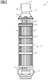
- the nuclear fuel assembly 2 of Figure 1 comprises a bundle of nuclear fuel rods 4 and a skeleton 6 for supporting the fuel rods 4.
- the fuel rods 4 extend parallel to each other and to an assembly axis L.
- the skeleton 6 comprises a bottom nozzle 8, a top nozzle 10, a plurality of guide thimbles 12 and a plurality of spacer grids 14.
- the bottom nozzle 8 and the top nozzle 10 are spaced along the assembly axis L.
- the guide thimbles 12 extend parallel to the assembly axis L and connect the bottom nozzle 8 to the top nozzle 10 with maintaining a predetermined spacing along assembly axis L between the bottom nozzle 8 and the top nozzle 10.
- the fuel rods 4 are received between the bottom nozzle 8 and the top nozzle 10.
- the spacer grids 14 are distributed along the bundle of fuel rods 4. Each spacer grid 14 is fixedly attached to the guide thimbles 12, with the guide thimbles extending through the spacer grid 14.
- Each spacer grid 14 is configured for supporting the fuel rods 4 in a transversely spaced relationship.
- Each spacer grid 14 is configured for supporting the fuel rods 4 along the assembly axis L and transversely to the assembly axis L.
- the nuclear fuel assembly 2 is inserted in a reactor core inside a reactor vessel, between a lower core plate and an upper core plate.
- the bottom nozzle 8 is configured to rest onto the lower core plate.
- the top nozzle 10 is configured to bear against the upper core plate with urging the nuclear fuel assembly 2 downwardly against the hydraulic lift-up force.
- the top nozzle 10 extends along a nozzle axis N.
- the nozzle axis N coincides with the assembly axis L.
- the top nozzle 10 comprises a lower part 16 that is fixedly attached to the guide thimbles 12 and an upper part 18 that is movable along the nozzle axis N relative to the lower part 16.
- the upper part 18 is configured for resting onto the upper core plate.
- the top nozzle 10 comprises a hold-down device 20 configured for pushing the upper part 18 upwardly relative to the lower part 16 along the nozzle axis N.
- the hold-down device 20 comprises a lower plate 22, an upper plate 24 axially spaced from the lower plate 22, and an intermediate plate 26 provided between the lower plate 22 and the upper plate 24, the intermediate plate 26 being axially movable along the nozzle axis N relative to lower plate 22 and the upper plate 24, between and upper position ( Figure 2 ) and a lower position ( Figure 4 ).
- the lower plate 22 and the upper plate 24 are maintained at fixed positions along the nozzle axis N.
- the lower plate 22 and the upper plate 24 are connected one to the other via connection elements, the intermediate plate 26 moving axially between the lower plate 22 and the upper plate 24 with sliding along the connection elements.
- the lower plate 22 and the upper plate 24 are connected via the connection elements such that the lower plate 22 and the upper plate 24 are maintained at respective fixed positions along the connection elements.
- the upper plate 24 is fixed axially relative to the connection elements and/or the lower plate 22 is permanently pushed downwardly by at least one elastic member in abutment against at least one lower stop member limiting a downward movement of the lower plate 22 along the connection elements.
- connection elements comprise for example guide thimbles 12 of the nuclear fuel assembly 2.
- the guide thimbles 12 extend through the lower plate 22, the upper plate 24 and the intermediate plate 26.
- the lower plate 22 is retained axially along the guide thimbles 12 such as to limit a downward movement of the lower plate 22 relative to the guide thimbles 12.
- At least one guide thimble 12 or each guide thimble 12 is for example provided with a lower stop member limiting a downward movement of the lower plate 22 along the guide thimble 12.
- the lower stop member is for example a shoulder 12A of the guide thimble 12.
- the lower plate 22 is permanently pushed downwardly by one or several spring member(s).
- the upper plate 24 is for example maintained at a fixed position axially along the guide thimbles 12.
- the upper plate 24 is for example mounted on at least one guide thimble 12 or each the guide thimble 12 with being axially fixed between an upper shoulder 12B of the guide thimble 12 and a nut 27 screwed onto an external thread of the guide thimble 12.
- the intermediate plate 26 is slidable along the guide thimbles 12, between the lower plate 22 and the upper plate 24.
- the hold-down device 20 comprises at least one main spring member 28, each main spring member 28 being arranged between the lower plate 22 and the intermediate plate 26 such as to permanently push the intermediate plate 26 towards the upper plate 24.
- Each main spring member 28 is permanently active along the entire stroke of the intermediate plate 26 between the upper position ( Figure 2 ) and the lower position ( Figure 4 ).
- the lower plate 22 is permanently pushed downwardly by each main spring member 28, preferably in abutment against each lower stop member 12A. The lower plate 22 is thus maintained in a fixed position along the guide thimbles 12.
- the hold-down device 20 comprises one or several auxiliary spring member(s) 30, each auxiliary spring member 30 being arranged such as to push to intermediate plate 26 towards the upper plate 24 when the intermediate plate 26 is located between the lower position and an intermediate position associated to this auxiliary spring member 30 ( Figure 3 ), the intermediate position being located between the lower position and the upper position.
- Each auxiliary spring member 30 is arranged such as to be active to push the intermediate plate 26 towards the upper plate 24 when the intermediate plate 26 is located between the lower position and the associated intermediate position and to be inactive when the intermediate plate 26 is located between the associated intermediate position and the upper position.
- the intermediate plate 26 When the intermediate plate 26 is located between the lower position and the intermediate position associated to one or several auxiliary spring member(s) 30, the intermediate plate 26 is pushed towards the upper plate 24 by each main spring member 28 and by each auxiliary spring member 30 associated to this intermediate position.
- the intermediate plate 26 When the intermediate plate 26 is located between an intermediate position associated to one or several auxiliary spring member(s) 30 and the upper position, the intermediate plate 26 is pushed towards the upper plate 24 by each main spring member 28 without being pushed towards the upper plate 24 by each auxiliary spring member 30 associated to this intermediate position.
- the hold-down device 20 comprises a preload element 32 associated to each auxiliary spring member 30 and arranged such that the auxiliary spring member 30 abuts against the upper plate 24 via the preload element 32 when the intermediate plate 26 is located between the intermediate position associated to this auxiliary spring member 30 and the upper position.
- the preload element 32 associated to each auxiliary spring member 30 is configured such that the auxiliary spring member 30 abutting the upper plate 24 via the preload element 32 is preloaded.
- the preload element 32 extends for example through the intermediate plate 26, the auxiliary spring member 30 being located between the lower plate 22 and the intermediate plate 26 and abutting the upper plate 24 via the preload element 32 extending through the intermediate plate 26 when the intermediate plate 26 is between the intermediate position associated to the auxiliary spring member 30 and the upper position.
- Each guide thimble 12 has an upper axial portion 34 extending axially between the lower plate 22 and the upper plate 24.
- each guide thimble 12 extends through the intermediate plate 26.
- the intermediate plate 26 is provided with a respective opening 26A for the upper axial portion 34 of each guide thimble 12.
- Each main spring member 28 is for example a helical spring, having a lower end abutting the lower plate 22 and an upper end abutting the intermediate plate 26.
- Each main spring member 28 is for example fitted onto an upper axial portion 34 of a guide thimble 12 such that the main spring member 28 is guided by the upper axial portion 34 of the guide thimble 12.
- Each main spring member 28 is for example provided as a helical spring extending around the upper axial portion 34 onto which the main spring member 28 is fitted.
- Each auxiliary spring member 30 is for example a helical spring, having a lower end abutting the lower plate 22 and an upper end abutting the preload element 32.
- Each auxiliary spring member 30 is for example fitted onto an upper axial portion 34 of a guide thimble 12 such as to be guided by the upper axial portion 34 of the guide thimble 12.
- Each auxiliary spring member 30 is for example provided as a helical spring extending around the upper axial portion 34 onto which the auxiliary spring member 30 is fitted.
- Each preload element 32 is for example tubular and slidably fitted onto a guide thimble 12, axially between an auxiliary spring member 30 and the upper plate 24.
- Each preload element 32 has for example a lower bearing surface 32A onto which the auxiliary spring member 30 pushes to urge the preload element 32 upwardly, an upper bearing surface 32B abutting the upper plate 24 when the intermediate plate is between the intermediate position and the upper position and an activation bearing surface 32C abutting the intermediate plate 26 when the intermediate plate 26 is located between the intermediate position and the lower position.
- the intermediate plate 26 is slidable along the preload element 32 between the intermediate position and the upper position.
- the auxiliary spring member 30 pushes onto the intermediate plate 26 via the preload element 32.
- the auxiliary spring member 30 is bearing onto the lower bearing surface 32A and the intermediate plate 26 is bearing onto the activation bearing surface 32C.
- the lower plate 22 is permanently urged downwardly by each auxiliary spring member 30, preferably in abutment against each lower stop member 12.
- the main spring member(s) 28 and the auxiliary spring member(s) 30 permanently urge the lower plate 22 downwardly with maintaining lower plate 22 in abutment against each lower stop member 12A, in a fixed position along the guide thimbles 12.
- the top nozzle 10 comprises a retaining member 40 configured to limit the axial movement of the intermediate plate 26 towards the upper plate 24 relative to the lower plate 22.
- a retaining member 40 is useful e.g. during mounting/dismounting operations, in particular in the present case upon removing nuts 27.
- the retaining member 40 is for example elongated axially and comprised a fixed end 42 fixedly attached to one of the lower plate 22 and the intermediate plate 26, the retaining member 40 sliding axially through a hole provide in the other one of the lower plate 22 and the intermediate plate 26.
- the other end 44 of the retaining member 40 is provided with a stop member 46 for limiting the spacing between the lower plate 22 and the intermediate plate 26.
- the fixed end 42 is fixedly attached to the intermediate plate 26, the retaining member 40 sliding axially through a hole provided in the lower plate 22, the other end 44 of the retaining member 40 being provided with the stop member 46.
- the lower part 16 of the top nozzle 10 is rigidly connected to the lower plate 22 and the upper part 18 of the top nozzle 10 is rigidly connected to the intermediate plate 26, such that the intermediate plate 26 moves axially with the upper part 18.
- the lower part 16 and the upper part 18 are preferably tubular and telescopically mounted one onto the other, the lower plate 22 being received inside the lower part 16 and the upper plate 24 and the intermediate plate 26 being received inside the upper part 18.
- the upper part 18 of the top nozzle 10 is for example initially in an uppermost position, the intermediate plate 26 being thus its upper position adjacent the upper plate 24.
- the main spring member(s) 28 push the intermediate plate 26 and the lower plate 22 away from each other but the auxiliary spring member 30 is inactive and does not act on the intermediate plate 26.
- the hold-down force generated by the hold-down device 20 is generated only by the main spring member(s) 28.
- the intermediate plate 26 does not abut against the preload element 32 associated to this auxiliary spring member 30 which abuts against the upper plate 24 via the preload element 32.
- the intermediate plate 26 When the intermediate plate 26 reaches the intermediate position associated to an auxiliary spring member 30 and is located between the intermediate position and the lower position, the main spring member(s) 28 and the auxiliary spring member 30 are simultaneously active and cooperate to push the intermediate plate 26 upwardly.
- the hold-down force generated by the hold-down device 20 is generated jointly by the main spring member(s) 28 and by each auxiliary spring member 30 associated to this intermediate position or to a lower intermediate position.
- the hold-down force generated by the hold-down device 20 becomes higher when the intermediate plate 26 moves below each intermediate position, with a step in the hold-down force generated when the intermediate plate 26 passes the intermediate position due to the preload of the auxiliary spring member(s) 30.
- the intermediate plate 26 tends to move up relative to the lower plate 22 in normal operating conditions and to move down in cold startup condition.
- main spring member(s) 28 and auxiliary spring member(s) 30 are simultaneously acting to provide the maximum hold-down force.
- each auxiliary spring member 30 decreases until the intermediate plate 26 reaches the associated intermediate position and the auxiliary spring member 30 abuts against the upper plate 24 via the associated preload element 32.
- the hold-down force is decreased by a force step corresponding to the preload of the auxiliary spring member(s) 30 associated to this intermediate position.
- the hold-down force follows the load required to avoid a lift off of the nuclear fuel assembly in the different operating conditions.
- the stepped hold-down system can be dimensioned in a way that in the lifetime of the fuel assembly, due to irradiation-induced lengthening of the fuel assembly, the auxiliary spring member(s) 30 become active during the operating conditions such as to compensate a loss of hold-down force due to relaxation of spring members 28 and 30 can be compensated.
- the overall hold-down force can stay relatively constant over the irradiation time.
- the stepped hold-down system While avoiding fuel assembly lift-off in both cold startup conditions and hot operating conditions, the stepped hold-down system reduces the excess hold-down forces in normal (hot) operating conditions. The mechanical stresses exerted over the lifetime of the fuel assembly are significantly reduced, which results in lower fuel assembly bow.
- the lower plate 22 and the upper plate 24 are connected via guide thimbles 12.
- the lower plate 22 and the upper plate 24 are connected one to the other with connection elements distinct from the guide thimbles 12.
- the main spring member(s) 28 and the auxiliary spring member(s) 30 are optionally fitted onto the connection elements such as to the guided by said connection elements.
- connection elements the lower plate 22 and the upper plate 24 are connected one to the other via connection elements, the main spring member(s) 28 and the auxiliary spring member(s) 30 being optionally fitted onto the connection elements such as to the guided by said connection elements.
- the hold-down device 20 may be configured such that the hold-down force generated by the hold-down device 20 has one single step or several successive steps along the axial movement of the intermediate plate 26.
- the hold-down device 20 comprises for example one single intermediate position or several successive intermediate positions with the hold-down force generated by the hold-down device 20 exhibiting a step at the or each intermediate position, with one or several auxiliary spring member(s) 30 being associated to each intermediate position.
- the intermediate positions are distinct from each other.
- the hold-down device comprises at least a first intermediate position and a second intermediate position distinct from the first intermediate position, one or several first auxiliary spring member(s) 30 associated to the first intermediate position and one or several second auxiliary spring member(s) 30 associated to the second intermediate position.
- the second intermediate position is e.g. lower than the first intermediate position, i.e. closer to the lower position than the first intermediate position.
Landscapes
- Physics & Mathematics (AREA)
- Engineering & Computer Science (AREA)
- Plasma & Fusion (AREA)
- General Engineering & Computer Science (AREA)
- High Energy & Nuclear Physics (AREA)
- Monitoring And Testing Of Nuclear Reactors (AREA)
- Fuel-Injection Apparatus (AREA)
Abstract
Description
- The present invention relates to a top nozzle for a nuclear fuel assembly.
- A nuclear fuel assembly (or "fuel assembly") comprises nuclear fuel rods (or "fuel rods") arranged in a bundle and a skeleton supporting the fuel rods.
- Each fuel rod comprises a tubular cladding containing nuclear fuel (e.g. nuclear fuel pellets, in particular UO2 pellets), the two ends of the tubular cladding being closed by respective end plugs.
- The skeleton comprises for example a bottom nozzle and a top nozzle spaced along an assembly axis, guide thimbles extending along the assembly axis between the bottom nozzle and the top nozzle with connecting the bottom nozzle and the top nozzle together, and spacer grids attached to the guide thimbles with being distributed along the guide thimbles, between the bottom nozzle and the top nozzle.
- The fuel rods extend between the bottom nozzle and the top nozzle with passing through the spacer grids. The function of the spacer grids is to support the fuel rods along the assembly axis and transversely to the assembly axis with maintaining the fuel rods in a spaced relationship.
- In operation, the fuel assembly is inserted into a reactor core received into a reactor vessel, with the longitudinal axis of the fuel assembly extending substantially vertically, and a coolant flows vertically through the fuel assembly for moderating the nuclear reaction and for retrieving heat produced by the fuel rods.
- The coolant flowing upwardly through the fuel assembly generates a force that tends to lift-off the fuel assembly. This force is generally called the "hydraulic lift force". The hydraulic lift force can overcome the weight of the fuel assembly.
- In view of counteracting the hydraulic lift force, the fuel assembly is generally provided with a hold-down device that is configured to bias the fuel assembly downwardly.
- The hold-down device is for example provided on the top nozzle and is configured to bear onto a reactor upper plate for pushing the fuel assembly downwardly. The hold-down device comprises spring members that generate a force that is substantially linearly proportional to the deflection of the spring members.
- The hold-down force required to prevent fuel assembly lift-off varies with different operating conditions since the hydraulic lift force depends on the coolant temperature (since the coolant temperature influence the coolant density and thus the hydraulic lift force) and the volume flow rate of the coolant through the reactor.
- During cold reactor startup, the coolant density is high which results in a high hydraulic lift force and the required hold-down force is high. In normal power operation, the coolant density is low and the required hold-down force is low.
- Besides, due to differential thermal expansion between the fuel assembly and the reactor vessel, the hold-down force generated by the hold-down device varies with the temperature. For example, an increase in temperature of the nuclear reactor results in a reduction of the hold-down force generated by the hold-down device.
- Despite this effect, the hold-down force generated by the hold-down device during hot operating conditions is generally higher than necessary since the lower coolant density also results in a lower hydraulic lift force.
- Besides, irradiation of the fuel assembly generally causes a decrease of the hold-down force due to spring relaxation during the lifetime of the fuel assembly. This is compensated by providing a hold-down device that generates a higher hold-down force than necessary before irradiation of the fuel assembly.
- As a consequence, the hold-down device exerts unnecessarily high levels of mechanical stress onto the fuel assembly structure, which is one of the main causes for fuel assembly bow.
- The consequences of fuel assembly bow include difficulties during handling operations such as loading / unloading the fuel assembly into or out from the reactor core and safety concerns such as incomplete insertion of control rods inserted into the guide thimbles for lowering the nuclear reactivity of the nuclear fuel assembly.
- One of the aims of the invention is to propose a hold-down device that allows better tuning of the hold-down force.
- To this end, the invention proposes a top nozzle for a nuclear fuel assembly, the top nozzle extending along a nozzle axis and comprising:
- a lower plate;
- an upper plate axially spaced from the lower plate;
- an intermediate plate axially positioned between the upper plate and the lower plate with being axially movable between an upper position and a lower position;
- one or several main spring member(s), each main spring member being arranged such as to permanently push the intermediate plate towards the upper plate;
- one or several spring member(s), each auxiliary spring member being arranged to push to intermediate plate towards the upper plate when the intermediate plate is located between the lower position and an intermediate position associated to this auxiliary spring member; and
- a preload element associated to each auxiliary spring member with being arranged such that the auxiliary spring member abuts against the upper plate via the preload element when the intermediate plate is located between the intermediate position associated to said auxiliary spring member and the upper position.
- The top nozzle incorporating such a hold-down device provides better tuning of the hold-down force for various operating conditions and during the lifetime of the fuel assembly, thus allowing a reduction of the risk for fuel assembly bow.
- The hold-down device provides for sufficient and need-tailored hold-down force at cold operating conditions (e.g. starting phase of an operating cycle) during which the main spring member(s) and at least one of the auxiliary spring member(s) is(are) active to generate the hold-down force, while allowing for a decrease of the hold-down force at hot operating conditions (e.g. normal operating cycle), during which only the main spring member(s) is(are) active, the auxiliary spring member(s) no longer acting onto the intermediate plate.
- In specific embodiments, the top nozzle comprises one or several of the following optional features, taken individually or according to any technically feasible combination:
- each preload element extends through the intermediate plate;
- the lower plate is connected to the upper plate via at least one connection element, each connection element extending axially between the lower plate and the upper plate;
- each main spring member is fitted onto a said connection element;
- each connection element onto which a main spring member is fitted is a tube, in particular a guide thimble;
- each auxiliary spring member is fitted onto a said connection element;
- each connection element onto which an auxiliary spring member is fitted is a tube, in particular a guide thimble;
- it comprises a retaining member configured to limit the axial movement of the intermediate plate towards the upper plate;
- the retaining member is elongated axially and comprising a fixed end fixedly attached to one of the lower plate and the upper plate, the retaining member sliding axially through the other one of the lower plate and the upper plate;
- it comprises a lower part and an upper part which are tubular, the lower part and the upper part being telescopically mounted one onto the other along the nozzle axis, the intermediate plate being receive inside the upper part with being fixedly attached to the upper part and the lower plate being received inside the lower part with being fixedly attached to the lower part.
- The invention also relates to a nuclear fuel assembly extending along a longitudinal axis and a bottom nozzle, a top nozzle as defined above, guide thimbles extending between the bottom nozzle and the top nozzle with connecting the bottom nozzle and the top nozzle, nuclear fuel rods positioned between the bottom nozzle and the top nozzle, and spacer grids fixedly attached to the guide thimbles, the nuclear fuel rods extending between the bottom nozzle and the top nozzle with passing through the spacer grids.
- The invention and its advantages will be better understood upon reading the following description, given solely by way of non-limiting example and with reference to the appended drawings, on which:
-
Figure 1 is a side elevation view of a nuclear fuel assembly comprising a top nozzle incorporating a hold-down device; -
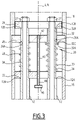
Figure 2 - 4 are cross-sectional views of the hold-down device in three different configurations. - The
nuclear fuel assembly 2 ofFigure 1 comprises a bundle ofnuclear fuel rods 4 and askeleton 6 for supporting thefuel rods 4. Thefuel rods 4 extend parallel to each other and to an assembly axis L. - The
skeleton 6 comprises abottom nozzle 8, atop nozzle 10, a plurality of guide thimbles 12 and a plurality ofspacer grids 14. - The
bottom nozzle 8 and thetop nozzle 10 are spaced along the assembly axis L. The guide thimbles 12 extend parallel to the assembly axis L and connect thebottom nozzle 8 to thetop nozzle 10 with maintaining a predetermined spacing along assembly axis L between thebottom nozzle 8 and thetop nozzle 10. Thefuel rods 4 are received between thebottom nozzle 8 and thetop nozzle 10. - The
spacer grids 14 are distributed along the bundle offuel rods 4. Eachspacer grid 14 is fixedly attached to theguide thimbles 12, with the guide thimbles extending through thespacer grid 14. - The
fuel rods 4 extend through thespaced grids 14. Eachspacer grid 14 is configured for supporting thefuel rods 4 in a transversely spaced relationship. Eachspacer grid 14 is configured for supporting thefuel rods 4 along the assembly axis L and transversely to the assembly axis L. - In operation, the
nuclear fuel assembly 2 is inserted in a reactor core inside a reactor vessel, between a lower core plate and an upper core plate. Thebottom nozzle 8 is configured to rest onto the lower core plate. Thetop nozzle 10 is configured to bear against the upper core plate with urging thenuclear fuel assembly 2 downwardly against the hydraulic lift-up force. - As visible on
Figure 1 , thetop nozzle 10 extends along a nozzle axis N. The nozzle axis N coincides with the assembly axis L. - The
top nozzle 10 comprises alower part 16 that is fixedly attached to theguide thimbles 12 and anupper part 18 that is movable along the nozzle axis N relative to thelower part 16. Theupper part 18 is configured for resting onto the upper core plate. - As illustrated on
Figures 2 - 4 , thetop nozzle 10 comprises a hold-down device 20 configured for pushing theupper part 18 upwardly relative to thelower part 16 along the nozzle axis N. - Hence, when the
upper part 18 abuts the upper core plate, thelower part 16 is pushed downwardly and thefuel assembly 2 is thus pushed downwardly to hold-down thefuel assembly 2 against hydraulic lift force. - The hold-down
device 20 comprises alower plate 22, anupper plate 24 axially spaced from thelower plate 22, and anintermediate plate 26 provided between thelower plate 22 and theupper plate 24, theintermediate plate 26 being axially movable along the nozzle axis N relative tolower plate 22 and theupper plate 24, between and upper position (Figure 2 ) and a lower position (Figure 4 ). - Preferably, the
lower plate 22 and theupper plate 24 are maintained at fixed positions along the nozzle axis N. - In one example, the
lower plate 22 and theupper plate 24 are connected one to the other via connection elements, theintermediate plate 26 moving axially between thelower plate 22 and theupper plate 24 with sliding along the connection elements. - Preferably, the
lower plate 22 and theupper plate 24 are connected via the connection elements such that thelower plate 22 and theupper plate 24 are maintained at respective fixed positions along the connection elements. - In a particular embodiment, the
upper plate 24 is fixed axially relative to the connection elements and/or thelower plate 22 is permanently pushed downwardly by at least one elastic member in abutment against at least one lower stop member limiting a downward movement of thelower plate 22 along the connection elements. - As illustrated on
Figures 2 - 4 , the connection elements comprise for example guidethimbles 12 of thenuclear fuel assembly 2. - The guide thimbles 12 extend through the
lower plate 22, theupper plate 24 and theintermediate plate 26. - The
lower plate 22 is retained axially along theguide thimbles 12 such as to limit a downward movement of thelower plate 22 relative to the guide thimbles 12. - In this view, at least one
guide thimble 12 or eachguide thimble 12 is for example provided with a lower stop member limiting a downward movement of thelower plate 22 along theguide thimble 12. The lower stop member is for example ashoulder 12A of theguide thimble 12. - As it will be explained later, the
lower plate 22 is permanently pushed downwardly by one or several spring member(s). - The
upper plate 24 is for example maintained at a fixed position axially along the guide thimbles 12. - In this view, the
upper plate 24 is for example mounted on at least oneguide thimble 12 or each theguide thimble 12 with being axially fixed between anupper shoulder 12B of theguide thimble 12 and anut 27 screwed onto an external thread of theguide thimble 12. - The
intermediate plate 26 is slidable along theguide thimbles 12, between thelower plate 22 and theupper plate 24. - The hold-down
device 20 comprises at least onemain spring member 28, eachmain spring member 28 being arranged between thelower plate 22 and theintermediate plate 26 such as to permanently push theintermediate plate 26 towards theupper plate 24. - Each
main spring member 28 is permanently active along the entire stroke of theintermediate plate 26 between the upper position (Figure 2 ) and the lower position (Figure 4 ). - The
lower plate 22 is permanently pushed downwardly by eachmain spring member 28, preferably in abutment against eachlower stop member 12A. Thelower plate 22 is thus maintained in a fixed position along the guide thimbles 12. - The hold-down
device 20 comprises one or several auxiliary spring member(s) 30, eachauxiliary spring member 30 being arranged such as to push tointermediate plate 26 towards theupper plate 24 when theintermediate plate 26 is located between the lower position and an intermediate position associated to this auxiliary spring member 30 (Figure 3 ), the intermediate position being located between the lower position and the upper position. - Each
auxiliary spring member 30 is arranged such as to be active to push theintermediate plate 26 towards theupper plate 24 when theintermediate plate 26 is located between the lower position and the associated intermediate position and to be inactive when theintermediate plate 26 is located between the associated intermediate position and the upper position. - When the
intermediate plate 26 is located between the lower position and the intermediate position associated to one or several auxiliary spring member(s) 30, theintermediate plate 26 is pushed towards theupper plate 24 by eachmain spring member 28 and by eachauxiliary spring member 30 associated to this intermediate position. - When the
intermediate plate 26 is located between an intermediate position associated to one or several auxiliary spring member(s) 30 and the upper position, theintermediate plate 26 is pushed towards theupper plate 24 by eachmain spring member 28 without being pushed towards theupper plate 24 by eachauxiliary spring member 30 associated to this intermediate position. - The hold-down
device 20 comprises apreload element 32 associated to eachauxiliary spring member 30 and arranged such that theauxiliary spring member 30 abuts against theupper plate 24 via thepreload element 32 when theintermediate plate 26 is located between the intermediate position associated to thisauxiliary spring member 30 and the upper position. - The
preload element 32 associated to eachauxiliary spring member 30 is configured such that theauxiliary spring member 30 abutting theupper plate 24 via thepreload element 32 is preloaded. - The
preload element 32 extends for example through theintermediate plate 26, theauxiliary spring member 30 being located between thelower plate 22 and theintermediate plate 26 and abutting theupper plate 24 via thepreload element 32 extending through theintermediate plate 26 when theintermediate plate 26 is between the intermediate position associated to theauxiliary spring member 30 and the upper position. - In such an example, advantageously, when the
intermediate plate 26 is between the intermediate position associated to anauxiliary spring member 30 and the lower position, thisauxiliary spring member 30 abuts theintermediate plate 26 via thepreload element 32. - Each
guide thimble 12 has an upperaxial portion 34 extending axially between thelower plate 22 and theupper plate 24. - The upper
axial portion 34 of eachguide thimble 12 extends through theintermediate plate 26. Theintermediate plate 26 is provided with arespective opening 26A for the upperaxial portion 34 of eachguide thimble 12. - Each
main spring member 28 is for example a helical spring, having a lower end abutting thelower plate 22 and an upper end abutting theintermediate plate 26. - Each
main spring member 28 is for example fitted onto an upperaxial portion 34 of aguide thimble 12 such that themain spring member 28 is guided by the upperaxial portion 34 of theguide thimble 12. Eachmain spring member 28 is for example provided as a helical spring extending around the upperaxial portion 34 onto which themain spring member 28 is fitted. - Each
auxiliary spring member 30 is for example a helical spring, having a lower end abutting thelower plate 22 and an upper end abutting thepreload element 32. - Each
auxiliary spring member 30 is for example fitted onto an upperaxial portion 34 of aguide thimble 12 such as to be guided by the upperaxial portion 34 of theguide thimble 12. - Each
auxiliary spring member 30 is for example provided as a helical spring extending around the upperaxial portion 34 onto which theauxiliary spring member 30 is fitted. - Each
preload element 32 is for example tubular and slidably fitted onto aguide thimble 12, axially between anauxiliary spring member 30 and theupper plate 24. - Each
preload element 32 has for example alower bearing surface 32A onto which theauxiliary spring member 30 pushes to urge thepreload element 32 upwardly, anupper bearing surface 32B abutting theupper plate 24 when the intermediate plate is between the intermediate position and the upper position and anactivation bearing surface 32C abutting theintermediate plate 26 when theintermediate plate 26 is located between the intermediate position and the lower position. - The
intermediate plate 26 is slidable along thepreload element 32 between the intermediate position and the upper position. - When the
intermediate plate 26 is between the intermediate position associated to anauxiliary spring member 30 and the lower position, theauxiliary spring member 30 pushes onto theintermediate plate 26 via thepreload element 32. Theauxiliary spring member 30 is bearing onto thelower bearing surface 32A and theintermediate plate 26 is bearing onto theactivation bearing surface 32C. - When the
intermediate plate 26 is between the intermediate position associated to anauxiliary spring member 30 and the lower position, thepreload element 32 is moved downwardly towards thelower plate 22 jointly with theintermediate plate 26 such that thepreload element 32 no longer abuts the upper plate 24 (Figure 4 ). - The
lower plate 22 is permanently urged downwardly by eachauxiliary spring member 30, preferably in abutment against eachlower stop member 12. - In a preferred example, in the different positions, the main spring member(s) 28 and the auxiliary spring member(s) 30 permanently urge the
lower plate 22 downwardly with maintaininglower plate 22 in abutment against eachlower stop member 12A, in a fixed position along the guide thimbles 12. - Optionally, the
top nozzle 10 comprises a retainingmember 40 configured to limit the axial movement of theintermediate plate 26 towards theupper plate 24 relative to thelower plate 22. Such a retainingmember 40 is useful e.g. during mounting/dismounting operations, in particular in the present case upon removing nuts 27. - The retaining
member 40 is for example elongated axially and comprised afixed end 42 fixedly attached to one of thelower plate 22 and theintermediate plate 26, the retainingmember 40 sliding axially through a hole provide in the other one of thelower plate 22 and theintermediate plate 26. - Optionally, the
other end 44 of the retainingmember 40 is provided with astop member 46 for limiting the spacing between thelower plate 22 and theintermediate plate 26. - In one exemplary embodiment, the
fixed end 42 is fixedly attached to theintermediate plate 26, the retainingmember 40 sliding axially through a hole provided in thelower plate 22, theother end 44 of the retainingmember 40 being provided with thestop member 46. - The
lower part 16 of thetop nozzle 10 is rigidly connected to thelower plate 22 and theupper part 18 of thetop nozzle 10 is rigidly connected to theintermediate plate 26, such that theintermediate plate 26 moves axially with theupper part 18. - The
lower part 16 and theupper part 18 are preferably tubular and telescopically mounted one onto the other, thelower plate 22 being received inside thelower part 16 and theupper plate 24 and theintermediate plate 26 being received inside theupper part 18. - The operation of the hold-down
device 20 will now be described with reference toFigures 2 - 4 . - The
upper part 18 of thetop nozzle 10 is for example initially in an uppermost position, theintermediate plate 26 being thus its upper position adjacent theupper plate 24. - When the
upper part 18 of thetop nozzle 10 abuts the upper core plate, theupper part 18 tends to move downwardly, thus moving theintermediate plate 26 downwardly towards thelower plate 22. - As long as the
intermediate plate 26 is located between the upper position and the intermediate position associated to anauxiliary spring member 30, the main spring member(s) 28 push theintermediate plate 26 and thelower plate 22 away from each other but theauxiliary spring member 30 is inactive and does not act on theintermediate plate 26. The hold-down force generated by the hold-downdevice 20 is generated only by the main spring member(s) 28. - As long as the
intermediate plate 26 is located between the upper position and the intermediate position associated to anauxiliary spring member 30, theintermediate plate 26 does not abut against thepreload element 32 associated to thisauxiliary spring member 30 which abuts against theupper plate 24 via thepreload element 32. - When the
intermediate plate 26 reaches the intermediate position associated to anauxiliary spring member 30 and is located between the intermediate position and the lower position, the main spring member(s) 28 and theauxiliary spring member 30 are simultaneously active and cooperate to push theintermediate plate 26 upwardly. - Below a given intermediate position of the
intermediate plate 26, the hold-down force generated by the hold-downdevice 20 is generated jointly by the main spring member(s) 28 and by eachauxiliary spring member 30 associated to this intermediate position or to a lower intermediate position. - Hence, the hold-down force generated by the hold-down
device 20 becomes higher when theintermediate plate 26 moves below each intermediate position, with a step in the hold-down force generated when theintermediate plate 26 passes the intermediate position due to the preload of the auxiliary spring member(s) 30. - Due to differential thermal expansion of the reactor vessel and the nuclear fuel assembly, the
intermediate plate 26 tends to move up relative to thelower plate 22 in normal operating conditions and to move down in cold startup condition. - In cold startup condition, the main spring member(s) 28 and auxiliary spring member(s) 30 are simultaneously acting to provide the maximum hold-down force.
- With temperature increases, the
intermediate plate 26 tends to move up relative to thelower plate 22. The force generated by eachauxiliary spring member 30 decreases until theintermediate plate 26 reaches the associated intermediate position and theauxiliary spring member 30 abuts against theupper plate 24 via the associatedpreload element 32. - At each intermediate position of the
intermediate plate 26, the hold-down force is decreased by a force step corresponding to the preload of the auxiliary spring member(s) 30 associated to this intermediate position. - Using the hold-down
device 20 with a stepped force relative to the stroke of the upper part of thetop nozzle 10, the hold-down force follows the load required to avoid a lift off of the nuclear fuel assembly in the different operating conditions. - The stepped hold-down system can be dimensioned in a way that in the lifetime of the fuel assembly, due to irradiation-induced lengthening of the fuel assembly, the auxiliary spring member(s) 30 become active during the operating conditions such as to compensate a loss of hold-down force due to relaxation of
spring members - While avoiding fuel assembly lift-off in both cold startup conditions and hot operating conditions, the stepped hold-down system reduces the excess hold-down forces in normal (hot) operating conditions. The mechanical stresses exerted over the lifetime of the fuel assembly are significantly reduced, which results in lower fuel assembly bow.
- The invention is not limited to the examples and variant discussed above. Other examples and variants may be contemplated.
- In the illustrated example, the
lower plate 22 and theupper plate 24 are connected viaguide thimbles 12. - Alternatively or optionally, the
lower plate 22 and theupper plate 24 are connected one to the other with connection elements distinct from the guide thimbles 12. In such case, the main spring member(s) 28 and the auxiliary spring member(s) 30 are optionally fitted onto the connection elements such as to the guided by said connection elements. - Hence, in a general manner, the
lower plate 22 and theupper plate 24 are connected one to the other via connection elements, the main spring member(s) 28 and the auxiliary spring member(s) 30 being optionally fitted onto the connection elements such as to the guided by said connection elements. - Besides, the hold-down
device 20 may be configured such that the hold-down force generated by the hold-downdevice 20 has one single step or several successive steps along the axial movement of theintermediate plate 26. - In this view, the hold-down
device 20 comprises for example one single intermediate position or several successive intermediate positions with the hold-down force generated by the hold-downdevice 20 exhibiting a step at the or each intermediate position, with one or several auxiliary spring member(s) 30 being associated to each intermediate position. - When successive intermediate positions are provided, the intermediate positions are distinct from each other.
- In one example, the hold-down device comprises at least a first intermediate position and a second intermediate position distinct from the first intermediate position, one or several first auxiliary spring member(s) 30 associated to the first intermediate position and one or several second auxiliary spring member(s) 30 associated to the second intermediate position. The second intermediate position is e.g. lower than the first intermediate position, i.e. closer to the lower position than the first intermediate position.
Claims (11)
- Top nozzle for a nuclear fuel assembly, the top nozzle extending along a nozzle axis and comprising :- a lower plate (22);- an upper plate (24) axially spaced from the lower plate (22);- an intermediate plate (26) axially positioned between the upper plate (24) and the lower plate (22) with being axially movable between an upper position and a lower position;- one or several main spring member(s) (28), each main spring member (28) being arranged such as to permanently push the intermediate plate (26) towards the upper plate (24);- one or several spring member(s) (30), each auxiliary spring member (30) being arranged to push to intermediate plate (26) towards the upper plate (24) when the intermediate plate (26) is located between the lower position and an intermediate position associated to this auxiliary spring member (30); and- a preload element (32) associated to each auxiliary spring member (30) with being arranged such that the auxiliary spring member (30) abuts against the upper plate (24) via the preload element (32) when the intermediate plate (26) is located between the intermediate position associated to said auxiliary spring member (30) and the upper position.
- Top nozzle according to claim 1, wherein each preload element (32) extends through the intermediate plate (26).
- Top nozzle according to claim 1 or claim 2, wherein the lower plate (22) is connected to the upper plate (24) via at least one connection element, each connection element extending axially between the lower plate (22) and the upper plate (24).
- Top nozzle according to claim 3, wherein each main spring member (28) is fitted onto a said connection element.
- Top nozzle according to claim 4, wherein each connection element onto which a main spring member (28) is fitted is a tube, in particular a guide thimble (12).
- Top nozzle according to any one of claims 3 to 5, wherein each auxiliary spring member (30) is fitted onto a said connection element.
- Top nozzle according to claim 6, wherein each connection element onto which an auxiliary spring member (30) is fitted is a tube, in particular a guide thimble (12).
- Top nozzle according to any one of the preceding claims, comprising a retaining member (40) configured to limit the axial movement of the intermediate plate (26) towards the upper plate (24).
- Top nozzle according to claim 8, wherein the retaining member (40) is elongated axially and comprising a fixed end (42) fixedly attached to one of the lower plate (22) and the upper plate (24), the retaining member (40) sliding axially through the other one of the lower plate (22) and the upper plate (24).
- Top nozzle according to any one of the preceding claims, comprising a lower part (16) and an upper part (18) which are tubular, the lower part (16) and the upper part (18) being telescopically mounted one onto the other along the nozzle axis (N), the intermediate plate (26) being receive inside the upper part (18) with being fixedly attached to the upper part (18) and the lower plate (22) being received inside the lower part (16) with being fixedly attached to the lower part (16).
- Nuclear fuel assembly extending along a longitudinal axis (L) and a bottom nozzle (8), a top nozzle (10) as in any one of the preceding claims, guide thimbles (12) extending between the bottom nozzle (8) and the top nozzle (10) with connecting the bottom nozzle (8) and the top nozzle (10), nuclear fuel rods (4) positioned between the bottom nozzle (8) and the top nozzle (10), and spacer grids (14) fixedly attached to the guide thimbles (12), the nuclear fuel rods (4) extending between the bottom nozzle (8) and the top nozzle (10) with passing through the spacer grids (14).
Priority Applications (5)
| Application Number | Priority Date | Filing Date | Title |
|---|---|---|---|
| EP21305504.9A EP4075447A1 (en) | 2021-04-16 | 2021-04-16 | Nuclear fuel assembly top nozzle comprising a hold-down device |
| PCT/EP2022/059867 WO2022219041A1 (en) | 2021-04-16 | 2022-04-13 | Nuclear fuel assembly top nozzle comprising a hold-down device |
| ES22723039T ES3029008T3 (en) | 2021-04-16 | 2022-04-13 | Nuclear fuel assembly top nozzle comprising a hold-down device |
| CN202280028898.6A CN117157717A (en) | 2021-04-16 | 2022-04-13 | Nuclear fuel assembly top nozzle including hold down device |
| EP22723039.8A EP4323999B1 (en) | 2021-04-16 | 2022-04-13 | Nuclear fuel assembly top nozzle comprising a hold-down device |
Applications Claiming Priority (1)
| Application Number | Priority Date | Filing Date | Title |
|---|---|---|---|
| EP21305504.9A EP4075447A1 (en) | 2021-04-16 | 2021-04-16 | Nuclear fuel assembly top nozzle comprising a hold-down device |
Publications (1)
| Publication Number | Publication Date |
|---|---|
| EP4075447A1 true EP4075447A1 (en) | 2022-10-19 |
Family
ID=76641623
Family Applications (2)
| Application Number | Title | Priority Date | Filing Date |
|---|---|---|---|
| EP21305504.9A Withdrawn EP4075447A1 (en) | 2021-04-16 | 2021-04-16 | Nuclear fuel assembly top nozzle comprising a hold-down device |
| EP22723039.8A Active EP4323999B1 (en) | 2021-04-16 | 2022-04-13 | Nuclear fuel assembly top nozzle comprising a hold-down device |
Family Applications After (1)
| Application Number | Title | Priority Date | Filing Date |
|---|---|---|---|
| EP22723039.8A Active EP4323999B1 (en) | 2021-04-16 | 2022-04-13 | Nuclear fuel assembly top nozzle comprising a hold-down device |
Country Status (4)
| Country | Link |
|---|---|
| EP (2) | EP4075447A1 (en) |
| CN (1) | CN117157717A (en) |
| ES (1) | ES3029008T3 (en) |
| WO (1) | WO2022219041A1 (en) |
Citations (1)
| Publication number | Priority date | Publication date | Assignee | Title |
|---|---|---|---|---|
| FR2693825A1 (en) * | 1992-07-20 | 1994-01-21 | Framatome Sa | Nuclear fuel assembly with axial guide tubes - whose upper ends attach to a plate axially slidable inside upper sleeve to accommodate tube deformation |
Family Cites Families (7)
| Publication number | Priority date | Publication date | Assignee | Title |
|---|---|---|---|---|
| US4534933A (en) * | 1983-10-17 | 1985-08-13 | Westinghouse Electric Corp. | Nuclear reactor fuel assembly with improved top nozzle and hold-down means |
| CN85106420A (en) * | 1985-08-26 | 1987-03-11 | 西屋电气公司 | Single neutron source localization mechanism for nuclear reactor fuel assembly |
| US4986959A (en) * | 1989-05-17 | 1991-01-22 | Westinghouse Electric Corp. | Nuclear fuel assembly with expandable top nozzle subassembly |
| KR100775575B1 (en) * | 2006-06-12 | 2007-11-13 | 한전원자력연료 주식회사 | Top Fixture for Nuclear Fuel Assembly Using Double Push Springs |
| EP2525361A1 (en) * | 2011-05-20 | 2012-11-21 | Areva NP | Lower nozzle for use in nuclear fuel assembly |
| US10818401B2 (en) * | 2016-02-02 | 2020-10-27 | Westinghouse Electric Company Llc | Spring apparatus and support apparatus usable in nuclear installation |
| CN107477140A (en) * | 2017-09-20 | 2017-12-15 | 高文英 | A kind of automobile absorber with multi-buffer function |
-
2021
- 2021-04-16 EP EP21305504.9A patent/EP4075447A1/en not_active Withdrawn
-
2022
- 2022-04-13 EP EP22723039.8A patent/EP4323999B1/en active Active
- 2022-04-13 WO PCT/EP2022/059867 patent/WO2022219041A1/en not_active Ceased
- 2022-04-13 CN CN202280028898.6A patent/CN117157717A/en active Pending
- 2022-04-13 ES ES22723039T patent/ES3029008T3/en active Active
Patent Citations (1)
| Publication number | Priority date | Publication date | Assignee | Title |
|---|---|---|---|---|
| FR2693825A1 (en) * | 1992-07-20 | 1994-01-21 | Framatome Sa | Nuclear fuel assembly with axial guide tubes - whose upper ends attach to a plate axially slidable inside upper sleeve to accommodate tube deformation |
Also Published As
| Publication number | Publication date |
|---|---|
| EP4323999A1 (en) | 2024-02-21 |
| ES3029008T3 (en) | 2025-06-23 |
| CN117157717A (en) | 2023-12-01 |
| EP4323999B1 (en) | 2025-02-12 |
| WO2022219041A1 (en) | 2022-10-20 |
Similar Documents
| Publication | Publication Date | Title |
|---|---|---|
| US4078967A (en) | Holddown device for nuclear fuel assembly | |
| US3770583A (en) | Fuel assembly hold-down device | |
| US3814667A (en) | Fuel assembly hold-down device | |
| US11120919B2 (en) | Small modular reactor fuel assembly | |
| US4420458A (en) | Nuclear fuel assembly with coolant conducting tube | |
| US8483348B2 (en) | Method of providing a hold-down force upon a nuclear fuel assembly | |
| EP2020661A1 (en) | Nuclear reactor control rod | |
| US4624827A (en) | Nuclear reactor control rod having a reduced worth tip | |
| EP4323999B1 (en) | Nuclear fuel assembly top nozzle comprising a hold-down device | |
| US4678628A (en) | Nuclear reactor control rod cluster for enthalpy rise compensation | |
| KR100892638B1 (en) | Top Fixture for Nuclear Fuel Assembly Using On-Off Actuated Push-Spring | |
| USRE31583E (en) | Fuel assembly hold-down device | |
| US6738447B1 (en) | High energy absorption top nozzle for a nuclear fuel assembly | |
| EP2363863B1 (en) | A protective grid attachment | |
| US4755346A (en) | Device for displacing and latching a cluster of control elements in a nuclear reactor | |
| US3936350A (en) | Nuclear reactor having thermally compensated support structure for a fuel assembly | |
| US11996207B2 (en) | Nuclear fuel assembly for a boiling water reactor with redundant load chain | |
| EA046520B1 (en) | FUEL ASSEMBLY HEAD CONTAINING A RETAINING DEVICE | |
| CN108604468B (en) | Spring device and support device usable in a nuclear installation | |
| US4684504A (en) | Bow resistant structural member for fuel assemblies in non-control rod locations of a nuclear reactor core | |
| US4233115A (en) | Safety apparatus for a nuclear reactor | |
| RU2748538C1 (en) | Fuel element of pressurized water-moderated nuclear power reactor | |
| EA046521B1 (en) | METHODS OF COMPOUND IDENTIFICATION | |
| KR100775575B1 (en) | Top Fixture for Nuclear Fuel Assembly Using Double Push Springs | |
| EP3573074B1 (en) | An auxiliary device for a fuel assembly, a fuel assembly, and a method of operating a pressurized water reactor |
Legal Events
| Date | Code | Title | Description |
|---|---|---|---|
| PUAI | Public reference made under article 153(3) epc to a published international application that has entered the european phase |
Free format text: ORIGINAL CODE: 0009012 |
|
| STAA | Information on the status of an ep patent application or granted ep patent |
Free format text: STATUS: THE APPLICATION HAS BEEN PUBLISHED |
|
| AK | Designated contracting states |
Kind code of ref document: A1 Designated state(s): AL AT BE BG CH CY CZ DE DK EE ES FI FR GB GR HR HU IE IS IT LI LT LU LV MC MK MT NL NO PL PT RO RS SE SI SK SM TR |
|
| STAA | Information on the status of an ep patent application or granted ep patent |
Free format text: STATUS: REQUEST FOR EXAMINATION WAS MADE |
|
| 17P | Request for examination filed |
Effective date: 20230320 |
|
| RBV | Designated contracting states (corrected) |
Designated state(s): AL AT BE BG CH CY CZ DE DK EE ES FI FR GB GR HR HU IE IS IT LI LT LU LV MC MK MT NL NO PL PT RO RS SE SI SK SM TR |
|
| GRAP | Despatch of communication of intention to grant a patent |
Free format text: ORIGINAL CODE: EPIDOSNIGR1 |
|
| STAA | Information on the status of an ep patent application or granted ep patent |
Free format text: STATUS: GRANT OF PATENT IS INTENDED |
|
| RIN1 | Information on inventor provided before grant (corrected) |
Inventor name: ECKSTEIN, DANIEL Inventor name: STREIT, DOMINIK Inventor name: LABARRIERE, ERIC |
|
| INTG | Intention to grant announced |
Effective date: 20230731 |
|
| STAA | Information on the status of an ep patent application or granted ep patent |
Free format text: STATUS: THE APPLICATION IS DEEMED TO BE WITHDRAWN |
|
| 18D | Application deemed to be withdrawn |
Effective date: 20231212 |