EP0206162B1 - Nuclear fuel assembly with bow-resistant structural members - Google Patents
Nuclear fuel assembly with bow-resistant structural members Download PDFInfo
- Publication number
- EP0206162B1 EP0206162B1 EP86108082A EP86108082A EP0206162B1 EP 0206162 B1 EP0206162 B1 EP 0206162B1 EP 86108082 A EP86108082 A EP 86108082A EP 86108082 A EP86108082 A EP 86108082A EP 0206162 B1 EP0206162 B1 EP 0206162B1
- Authority
- EP
- European Patent Office
- Prior art keywords
- fuel assembly
- tube
- creep
- resistant material
- assembly according
- Prior art date
- Legal status (The legal status is an assumption and is not a legal conclusion. Google has not performed a legal analysis and makes no representation as to the accuracy of the status listed.)
- Expired
Links
- 239000003758 nuclear fuel Substances 0.000 title description 4
- 239000000446 fuel Substances 0.000 claims description 73
- 239000000463 material Substances 0.000 claims description 26
- 238000005253 cladding Methods 0.000 claims description 19
- 230000006835 compression Effects 0.000 claims description 10
- 238000007906 compression Methods 0.000 claims description 10
- 239000008188 pellet Substances 0.000 claims description 10
- 239000006096 absorbing agent Substances 0.000 claims description 6
- 229910010293 ceramic material Inorganic materials 0.000 claims description 5
- 230000036316 preload Effects 0.000 claims description 4
- MCMNRKCIXSYSNV-UHFFFAOYSA-N ZrO2 Inorganic materials O=[Zr]=O MCMNRKCIXSYSNV-UHFFFAOYSA-N 0.000 claims description 3
- RVTZCBVAJQQJTK-UHFFFAOYSA-N oxygen(2-);zirconium(4+) Chemical compound [O-2].[O-2].[Zr+4] RVTZCBVAJQQJTK-UHFFFAOYSA-N 0.000 claims description 3
- 238000007789 sealing Methods 0.000 claims description 2
- 230000000712 assembly Effects 0.000 description 12
- 238000000429 assembly Methods 0.000 description 12
- ZOXJGFHDIHLPTG-UHFFFAOYSA-N Boron Chemical compound [B] ZOXJGFHDIHLPTG-UHFFFAOYSA-N 0.000 description 3
- 229910052796 boron Inorganic materials 0.000 description 3
- 239000002826 coolant Substances 0.000 description 3
- 238000010586 diagram Methods 0.000 description 3
- XLYOFNOQVPJJNP-UHFFFAOYSA-N water Substances O XLYOFNOQVPJJNP-UHFFFAOYSA-N 0.000 description 3
- 239000000919 ceramic Substances 0.000 description 2
- 229910052580 B4C Inorganic materials 0.000 description 1
- PNEYBMLMFCGWSK-UHFFFAOYSA-N aluminium oxide Inorganic materials [O-2].[O-2].[O-2].[Al+3].[Al+3] PNEYBMLMFCGWSK-UHFFFAOYSA-N 0.000 description 1
- 230000005540 biological transmission Effects 0.000 description 1
- INAHAJYZKVIDIZ-UHFFFAOYSA-N boron carbide Chemical compound B12B3B4C32B41 INAHAJYZKVIDIZ-UHFFFAOYSA-N 0.000 description 1
- 150000001875 compounds Chemical class 0.000 description 1
- 230000004992 fission Effects 0.000 description 1
- 239000007789 gas Substances 0.000 description 1
- 239000001307 helium Substances 0.000 description 1
- 229910052734 helium Inorganic materials 0.000 description 1
- SWQJXJOGLNCZEY-UHFFFAOYSA-N helium atom Chemical compound [He] SWQJXJOGLNCZEY-UHFFFAOYSA-N 0.000 description 1
- 239000007788 liquid Substances 0.000 description 1
- 238000004519 manufacturing process Methods 0.000 description 1
- 238000000034 method Methods 0.000 description 1
- 239000002574 poison Substances 0.000 description 1
- 231100000614 poison Toxicity 0.000 description 1
- 238000003825 pressing Methods 0.000 description 1
- 230000009257 reactivity Effects 0.000 description 1
Images


Classifications
-
- G—PHYSICS
- G21—NUCLEAR PHYSICS; NUCLEAR ENGINEERING
- G21C—NUCLEAR REACTORS
- G21C3/00—Reactor fuel elements and their assemblies; Selection of substances for use as reactor fuel elements
- G21C3/30—Assemblies of a number of fuel elements in the form of a rigid unit
- G21C3/32—Bundles of parallel pin-, rod-, or tube-shaped fuel elements
- G21C3/326—Bundles of parallel pin-, rod-, or tube-shaped fuel elements comprising fuel elements of different composition; comprising, in addition to the fuel elements, other pin-, rod-, or tube-shaped elements, e.g. control rods, grid support rods, fertile rods, poison rods or dummy rods
-
- G—PHYSICS
- G21—NUCLEAR PHYSICS; NUCLEAR ENGINEERING
- G21C—NUCLEAR REACTORS
- G21C3/00—Reactor fuel elements and their assemblies; Selection of substances for use as reactor fuel elements
- G21C3/30—Assemblies of a number of fuel elements in the form of a rigid unit
-
- G—PHYSICS
- G21—NUCLEAR PHYSICS; NUCLEAR ENGINEERING
- G21C—NUCLEAR REACTORS
- G21C3/00—Reactor fuel elements and their assemblies; Selection of substances for use as reactor fuel elements
- G21C3/02—Fuel elements
- G21C3/04—Constructional details
- G21C3/16—Details of the construction within the casing
-
- Y—GENERAL TAGGING OF NEW TECHNOLOGICAL DEVELOPMENTS; GENERAL TAGGING OF CROSS-SECTIONAL TECHNOLOGIES SPANNING OVER SEVERAL SECTIONS OF THE IPC; TECHNICAL SUBJECTS COVERED BY FORMER USPC CROSS-REFERENCE ART COLLECTIONS [XRACs] AND DIGESTS
- Y02—TECHNOLOGIES OR APPLICATIONS FOR MITIGATION OR ADAPTATION AGAINST CLIMATE CHANGE
- Y02E—REDUCTION OF GREENHOUSE GAS [GHG] EMISSIONS, RELATED TO ENERGY GENERATION, TRANSMISSION OR DISTRIBUTION
- Y02E30/00—Energy generation of nuclear origin
- Y02E30/30—Nuclear fission reactors
Definitions
- the present invention relates generally to fuel assemblies for nuclear reactors and, more particularly, to a fuel assembly especially for use in a non-control rod location of a nuclear reactor core.
- the cores of nuclear reactors conventionally include a plurality of fuel assemblies.
- all fuel assemblies are geometrically alike.
- Each fuel assembly includes a multiplicity of fuel rods held in an organized array by grids spaced along the fuel assembly.
- the grids are attached to a plurality of control rod guide thimbles.
- Top and bottom nozzles of the fuel assembly are secured to opposite ends of the control rod guide thimbles which extend above and below the opposite ends of the fuel rods.
- the guide thimbles together with the top and bottom nozzles rigidly attached thereto form the structural skeleton of the fuel assembly.
- control rods positioned for movement in the guide thimbles of the fuel assembly.
- control rods not all of the fuel assembly locations of a reactor core use control rods, only about one- third of the fuel assemblies being in control rod locations.
- PWR fuel assemblies have been constructed to be alike geometrically, the fuel assemblies for non-control rod locations have been the same as those for control rod locations.
- This separate fuel assembly includes a bottom nozzle, a top nozzle, elongate structural members, such as hollow tie rods which connect the top and bottom nozzles together and at least some of which contain a burnable poison, and axially spaced transverse grids which are attached to the structural members and support an array of fuel rods.
- the top and bottom nozzles are attached to the longitudinal structural members by suitable means, such as screw-thread connections.
- the structural members are the hollow guide thimble tubes which are open at the top and closed at the bottom (except for small holes for coolant flow). These guide thimble tubes are positioned within the fuel assembly so as to align with the control rods which are movable therein during reactor operation.
- the structural members although likewise in the form of tubes are not designed or intended to receive control rods but are available for different functional as well as structural uses.
- such structural member may contain burnable absorber material, e.g. a suitable compound of boron, such as used in modern reactors as an additional means for controlling reactivity, especially at the beginning of life of the nuclear fuel.
- burnable absorber material e.g. a suitable compound of boron, such as used in modern reactors as an additional means for controlling reactivity, especially at the beginning of life of the nuclear fuel.
- the elongate tube constituting the structural member is closed at each end by end plugs which are welded to the tube and preferably are made of Zircaloy-4.
- a spring holds the absorber material in place within the tube and provides a plenum for accumulating helium gas released when a neutron interacts with a boron atom.
- the tubes For assembling the non-control rod structural members into the fuel assembly, the tubes must be empty and open at one end. After the grids are bulge-fitted to the tubes, the absorber material and spring are loaded into the tubes whereupon the remaining end plugs are
- the former can have sixteen more fuel rods than the latter.
- non-control rod fuel assemblies having a design such as described above has created an opportunity to overcome a problem experienced for a long time and which affects the overall performance of PWR fuel assemblies, namely, the problem of fuel assembly bow due to the transmission of axial force through the hold-down springs of the top nozzle of the fuel assembly, the adapter plate of the top nozzle, the upper end plug of the longitudinal structural member, the cladding tube of the latter, and its lower end plug to the adapter plate of the bottom nozzle.
- the axial force thus transmitted places the cladding tube in a state of compression which can result in permanent fuel assembly bow.
- the solution proposed by the invention to the problem of fuel assembly bow involves preloading the cladding tube of the structural member in tension. Preloading the tube in tension requires the central part thereof to be loaded in compression.
- the material used for loading the tube in compression must be creep-resistant, i.e. it must not be subject to thermal or irradiation-induced creep as, otherwise, the structure will creep to a permanently bowed position.
- the invention resides in a fuel assembly for use in a nuclear reactor core, said fuel assembly including top and bottom nozzles and a plurality of longitudinal structural members extending between and attached to said nozzles so as to consolidate the fuel assembly into an integral unitary structure, said structural members having an axial load transmitted thereto through the unitary structure of the fuel assembly when in the reactor core, and at least some of said structural members each including an elongate hollow cladding tube and means secured the opposite ends of the tube for hermetically sealing the tube and for attaching it to the top and bottom nozzles, characterized in that said cladding tube contains a quantity of creep-resistant material, and pre-tensioning- means for applying a predetermined compressive load to said creep-resistant material and reacting said load so as to preload said cladding tube in a state of pre-tension having a magnitude sufficient to substantially counteract said axial load and thereby reduce compressive stress in said cladding tube.
- the creep-resistant material is a ceramic material, such as zirconium dioxide, in pellet form, the ceramic pellets being coated with a burnable absorber material.
- the pre-tensioning means is an elongate bellows-type device positioned within the cladding tube between one end thereof and the creep-resistant material, and internally pressurized to create a predetermined axial force which places the creep-resistant pellets in compression and the tube in said state of pre-tension. The remainder of the tube, i.e. the space not occupied by the creep-resistant material and the pre-tensioning means, may be pressurized.
- the pre-tensioning means is an arrangement of Belleville springs positioned within the tube between one end thereof and the creep-resistant material so as to create the predetermined axial force which places the creep-resistant material in compression and the tube in said state of pre-tension.
- the Belleville springs in the arrangement thereof are both stacked in parallel and in series.
- a fuel assembly 10 adapted for use in a non-control rod location of a nuclear reactor core (not shown) and comprising a lower end structure or bottom nozzle 12 for supporting the assembly on the lower core plate (not shown) in the reactor core, several elongate structural members 14 which at their lower ends are attached to the bottom nozzle 12 and which project upwardly therefrom, a plurality of transverse grids 16 axially spaced along the structural members 14, an organized array of elongate fuel rods 18 transversely spaced and supported by the grids 16, an instrumentation tube 20 located in the center of the assembly, and an upper end structure or top nozzle 22 attached to the upper ends of the structural members 14.
- These parts thus arranged form an integral unit capable of being conventionally handled without damaging the assembly parts.
- Each of the fuel rods 18 contains pellets 24 of fissile material and is closed at its opposite ends by means of end plugs 26 and 28.
- a liquid moderator-coolant such as water, or water containing boron, is pumped upwardly along the fuel rods 18 of the fuel assembly 10 in order to extract therefrom heat for the production of useful work.
- Figs. 2 and 3 they illustrate two embodiments of the invention.
- the fuel assembly 10 is designed to be used at a non-control rod core location in which there are no control rods operatively associated with the assembly.
- the longitudinal structural members 14 of the non-control rod fuel assembly 10 have their opposite ends sealed.
- the longitudinal structural member 14 comprises an elongate hollow cladding tube 30 closed at its opposite ends by means of end plugs 32 and 34 welded to the tube.
- the tube and the end plugs preferably consist of Zircaloy-4.
- the upper and lower end plugs 32, 34 have thereon threaded studs 38 and 40, respectively, which extend through openings in the adapter plates 42, 44 of the top and bottom nozzles 22, 12 and have nuts 46, 48 threadedly engaged therewith and tightened to rigidly secure the opposite ends of the structural member 14 to the respective nozzles 22, 12.
- the tubes 30 of the structural members 14 have a substantially greater wall thickness than the tubes of control-rod guide thimbles and there are substantially fewer structural members 14 in each non-control rod fuel assembly 10 than there are guide thimbles in each control-rod fuel assembly.
- the remaining locations in the non-control rod fuel assembly 10 which correspond to those occupied by guide thimbles in the control rod fuel assembly are occupied by fuel rods 18. For example, there are typically twenty-four guide thimbles in the control-rod fuel assembly, whereas in the non-control rod fuel assembly 10 there are only eight structural members 14 so that the sixteen remaining locations can be filled with additional fuel rods.
- each structural member 14 is made resistant to bowing by preloading its cladding tube 30 in pre-tension.
- the central portion thereof In order to preload the tube 30 in tension, the central portion thereof must be loaded in compression.
- the material loaded in compression must not be subject to thermal or irradiation-induced creep or it will creep to a permanently bowed condition.
- the tube 30 of the member 14 contains a material 50, preferably in the form of pellets stacked in the tube 30, which is resistant to thermal or irradiation-induced creep.
- Ceramic materials such as zirconium dioxide or alumina, are typical examples of materials which are very creep-resistant and which can also be coated with a burnable absorber material, such as boron carbide.
- the pre-tensioning means is a bellows type device, generally designated 52, disposed within the tube 30 in an upper plenum region of the structural member 14.
- the bellows device 52 is connected, e.g. welded, to the upper end plug 32 and is radially supported by the cladding tube 30, with the bottom end 54 of the device 52 pressing against the stack of pellets 50.
- a pressurizing passage 56 in the upper end plug 32 allows the bellows device 52 to be internally pressurized. After pressurization, the passsage 56 is sealed and an axial force then exists in the bellows device 52 which places the pellet stack 50 in compression and places the tube 30 in pre-tension.
- a bellows pressure of approximately 40 atmospheres (cold) will provide an axial force of about 54 kg during hot operating conditions. It should be noted that achievement of acceptable fuel assembly bow does noX-!f!Wre zero axial stress so that a lower pressure could be used.
- the inside of the member tube 30, in the pellet region can be pressurized through a passage 58 in the lower end plug 34. It should be noted that if this is pressurized, it counteracts the pressure in the bellows so that the bellows pressure must be increased accordingly.
- the pre-tensioning means is in the form of an arrangement of Belleville springs 60.
- the Belleville springs 60 can be stacked in parallel, as shown, to obtain a greater deflection range.
- the pretensioning means its function is to apply a predetermined compressive load to the creep-resistant material 50 in the member 14 and to react the load so as to preload the tube 30 in a state of pre-tension.
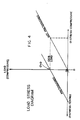
- the pre-tension should be of a magnitude sufficient to substantially counteract an axial load typically transmitted through the unitary structure of the fuel assembly 10 when installed in the reactor core, and thereby substantially reduce the compressive stress occurring in the tube 30 of the structural member 14 when the core plate compressive forces are applied to the hold-down springs 62 (Fig. 1) of the fuel assembly 10. This is shown in Fig.
- FIG. 4 which is a load-stress diagram comparing a structural member according to the invention with a structural member of the earlier design initially mentioned herein, and with all cladding and dimensional parameters being the same in both cases.
- the diagram shows that the pre-tensioned tube of the structural member embodying the invention has a much lower compressive stress for a given axial load than the non-pretensioned tube of the earlier design.
Landscapes
- Physics & Mathematics (AREA)
- Engineering & Computer Science (AREA)
- Plasma & Fusion (AREA)
- General Engineering & Computer Science (AREA)
- High Energy & Nuclear Physics (AREA)
- Monitoring And Testing Of Nuclear Reactors (AREA)
- Inert Electrodes (AREA)
- Fuel-Injection Apparatus (AREA)
Description
- The present invention relates generally to fuel assemblies for nuclear reactors and, more particularly, to a fuel assembly especially for use in a non-control rod location of a nuclear reactor core.
- The cores of nuclear reactors conventionally include a plurality of fuel assemblies. In a typical pressurized water reactor (PWR), all fuel assemblies are geometrically alike. Each fuel assembly includes a multiplicity of fuel rods held in an organized array by grids spaced along the fuel assembly. The grids are attached to a plurality of control rod guide thimbles. Top and bottom nozzles of the fuel assembly are secured to opposite ends of the control rod guide thimbles which extend above and below the opposite ends of the fuel rods. The guide thimbles together with the top and bottom nozzles rigidly attached thereto form the structural skeleton of the fuel assembly.
- The fission process created by nuclear fuel contained in the fuel rods is typically controlled by means of control rods positioned for movement in the guide thimbles of the fuel assembly. However, not all of the fuel assembly locations of a reactor core use control rods, only about one- third of the fuel assemblies being in control rod locations. Nevertheless, since heretofore all PWR fuel assemblies have been constructed to be alike geometrically, the fuel assemblies for non-control rod locations have been the same as those for control rod locations.
- In departure from this prior practice of constructing all PWR fuel assemblies alike, a separate fuel assembly design has been proposed recently for use at non-control rod locations. This separate fuel assembly includes a bottom nozzle, a top nozzle, elongate structural members, such as hollow tie rods which connect the top and bottom nozzles together and at least some of which contain a burnable poison, and axially spaced transverse grids which are attached to the structural members and support an array of fuel rods. The top and bottom nozzles are attached to the longitudinal structural members by suitable means, such as screw-thread connections. One important difference between this previously proposed fuel assembly for non-control rod locations and conventional fuel assemblies for non-control rod as well as control-rod locations lies in the design of the longitudinal structural members which interconnect the top and bottom nozzles to form the structural skeleton of the assembly. In a conventional PWR fuel assembly, the structural members are the hollow guide thimble tubes which are open at the top and closed at the bottom (except for small holes for coolant flow). These guide thimble tubes are positioned within the fuel assembly so as to align with the control rods which are movable therein during reactor operation. On the other hand, in the non-control rod fuel assembly intended for use in non-control rod core locations, the structural members, although likewise in the form of tubes are not designed or intended to receive control rods but are available for different functional as well as structural uses.
- Functionally, such structural member may contain burnable absorber material, e.g. a suitable compound of boron, such as used in modern reactors as an additional means for controlling reactivity, especially at the beginning of life of the nuclear fuel. Structurally, the elongate tube constituting the structural member is closed at each end by end plugs which are welded to the tube and preferably are made of Zircaloy-4. A spring holds the absorber material in place within the tube and provides a plenum for accumulating helium gas released when a neutron interacts with a boron atom. For assembling the non-control rod structural members into the fuel assembly, the tubes must be empty and open at one end. After the grids are bulge-fitted to the tubes, the absorber material and spring are loaded into the tubes whereupon the remaining end plugs are welded in place. The fuel rods are then loaded, and the top and bottom nozzles are bolted on.
- In the non-control rod fuel assembly, there are eight structural members whereas in the conventional control rod fuel assembly there are twenty-four guide thimbles. Thus, the former can have sixteen more fuel rods than the latter.
- The use of non-control rod fuel assemblies having a design such as described above has created an opportunity to overcome a problem experienced for a long time and which affects the overall performance of PWR fuel assemblies, namely, the problem of fuel assembly bow due to the transmission of axial force through the hold-down springs of the top nozzle of the fuel assembly, the adapter plate of the top nozzle, the upper end plug of the longitudinal structural member, the cladding tube of the latter, and its lower end plug to the adapter plate of the bottom nozzle. The axial force thus transmitted places the cladding tube in a state of compression which can result in permanent fuel assembly bow.
- It is the principal object of the invention to provide means for reducing compressive stressing of non-control rod-receiving longitudinal structural members of nuclear fuel assemblies.
- Basically, the solution proposed by the invention to the problem of fuel assembly bow involves preloading the cladding tube of the structural member in tension. Preloading the tube in tension requires the central part thereof to be loaded in compression. The material used for loading the tube in compression must be creep-resistant, i.e. it must not be subject to thermal or irradiation-induced creep as, otherwise, the structure will creep to a permanently bowed position.
- Accordingly, the invention resides in a fuel assembly for use in a nuclear reactor core, said fuel assembly including top and bottom nozzles and a plurality of longitudinal structural members extending between and attached to said nozzles so as to consolidate the fuel assembly into an integral unitary structure, said structural members having an axial load transmitted thereto through the unitary structure of the fuel assembly when in the reactor core, and at least some of said structural members each including an elongate hollow cladding tube and means secured the opposite ends of the tube for hermetically sealing the tube and for attaching it to the top and bottom nozzles, characterized in that said cladding tube contains a quantity of creep-resistant material, and pre-tensioning- means for applying a predetermined compressive load to said creep-resistant material and reacting said load so as to preload said cladding tube in a state of pre-tension having a magnitude sufficient to substantially counteract said axial load and thereby reduce compressive stress in said cladding tube.
- Preferably, the creep-resistant material is a ceramic material, such as zirconium dioxide, in pellet form, the ceramic pellets being coated with a burnable absorber material. In one embodiment of the invention, the pre-tensioning means is an elongate bellows-type device positioned within the cladding tube between one end thereof and the creep-resistant material, and internally pressurized to create a predetermined axial force which places the creep-resistant pellets in compression and the tube in said state of pre-tension. The remainder of the tube, i.e. the space not occupied by the creep-resistant material and the pre-tensioning means, may be pressurized. In an alternative embodiment, the pre-tensioning means is an arrangement of Belleville springs positioned within the tube between one end thereof and the creep-resistant material so as to create the predetermined axial force which places the creep-resistant material in compression and the tube in said state of pre-tension. The Belleville springs in the arrangement thereof are both stacked in parallel and in series.
- Preferred embodiments of the invention will now be described, by way of example only, with reference to the accompanying drawings, in which:
- Fig. 1 is an elevational view, with parts broken away for clarity and partially in section, of a non-control rod fuel assembly embodying the invention;
- Fig. 2 is an enlarged fragmentary view, in vertical section, of the fuel assembly of Fig. 1, showing one of its longitudinal structural members pre-tensioned in one manner;
- Fig. 3 is a view similar to Fig. 2 but illustrating an alternative way of placing a structural member of the fuel assembly in pre-tension; and
- Fig. 4 is a load-stress diagram comparing a longitudinal structural member of the earlier design with one embodying the present invention, and demonstrating that the pre-tensioned member according to the invention has much lower compressive stress for a given axial load than the non-pretensioned member of the earlier design.
- In the following description, like reference characters designate like or corresponding parts throughout the several views of the drawings, and terms such as "forward", "rearward", "left", "right", "upwardly", "downwardly", and the like are employed as words of convenience not to be construed as limiting terms.
- Referring now to the drawings, and particularly to Fig. 1, there is shown, in vertically foreshortened form, a
fuel assembly 10 adapted for use in a non-control rod location of a nuclear reactor core (not shown) and comprising a lower end structure orbottom nozzle 12 for supporting the assembly on the lower core plate (not shown) in the reactor core, several elongatestructural members 14 which at their lower ends are attached to thebottom nozzle 12 and which project upwardly therefrom, a plurality oftransverse grids 16 axially spaced along thestructural members 14, an organized array ofelongate fuel rods 18 transversely spaced and supported by thegrids 16, aninstrumentation tube 20 located in the center of the assembly, and an upper end structure ortop nozzle 22 attached to the upper ends of thestructural members 14. These parts thus arranged form an integral unit capable of being conventionally handled without damaging the assembly parts. - Each of the
fuel rods 18 containspellets 24 of fissile material and is closed at its opposite ends by means ofend plugs fuel rods 18 of thefuel assembly 10 in order to extract therefrom heat for the production of useful work. - Turning now to Figs. 2 and 3, they illustrate two embodiments of the invention. As initially indicated herein, the
fuel assembly 10 is designed to be used at a non-control rod core location in which there are no control rods operatively associated with the assembly. As distinct from the control-rod guide thimbles of fuel assemblies employed at control-rod core locations, into which control rods extend through the upper ends and coolant flow is introduced through the lower ends, the longitudinalstructural members 14 of the non-controlrod fuel assembly 10 have their opposite ends sealed. - In each of the two embodiments shown in Figs. 2 and 3, the longitudinal
structural member 14 comprises an elongatehollow cladding tube 30 closed at its opposite ends by means ofend plugs lower end plugs studs adapter plates bottom nozzles nuts structural member 14 to therespective nozzles tubes 30 of thestructural members 14 have a substantially greater wall thickness than the tubes of control-rod guide thimbles and there are substantially fewerstructural members 14 in each non-controlrod fuel assembly 10 than there are guide thimbles in each control-rod fuel assembly. The remaining locations in the non-controlrod fuel assembly 10 which correspond to those occupied by guide thimbles in the control rod fuel assembly are occupied byfuel rods 18. For example, there are typically twenty-four guide thimbles in the control-rod fuel assembly, whereas in the non-controlrod fuel assembly 10 there are only eightstructural members 14 so that the sixteen remaining locations can be filled with additional fuel rods. - In accordance with the present invention, each
structural member 14 is made resistant to bowing by preloading itscladding tube 30 in pre-tension. In order to preload thetube 30 in tension, the central portion thereof must be loaded in compression. The material loaded in compression must not be subject to thermal or irradiation-induced creep or it will creep to a permanently bowed condition. Thus, thetube 30 of themember 14 contains amaterial 50, preferably in the form of pellets stacked in thetube 30, which is resistant to thermal or irradiation-induced creep. Ceramic materials, such as zirconium dioxide or alumina, are typical examples of materials which are very creep-resistant and which can also be coated with a burnable absorber material, such as boron carbide. - For applying a compressive load to the
ceramic pellets 50 and reacting the load in such a way as to load thetube 30 in pre-tension, either one of the two kinds of pre-tensioning means depicted in Figs. 2 and 3 can be used. - In Fig. 2, the pre-tensioning means is a bellows type device, generally designated 52, disposed within the
tube 30 in an upper plenum region of thestructural member 14. Thebellows device 52 is connected, e.g. welded, to theupper end plug 32 and is radially supported by thecladding tube 30, with thebottom end 54 of thedevice 52 pressing against the stack ofpellets 50. A pressurizingpassage 56 in theupper end plug 32 allows thebellows device 52 to be internally pressurized. After pressurization, thepasssage 56 is sealed and an axial force then exists in thebellows device 52 which places thepellet stack 50 in compression and places thetube 30 in pre-tension. - A bellows pressure of approximately 40 atmospheres (cold) will provide an axial force of about 54 kg during hot operating conditions. It should be noted that achievement of acceptable fuel assembly bow does noX-!f!Wre zero axial stress so that a lower pressure could be used. If desired, the inside of the
member tube 30, in the pellet region, can be pressurized through apassage 58 in thelower end plug 34. It should be noted that if this is pressurized, it counteracts the pressure in the bellows so that the bellows pressure must be increased accordingly. - In the alternative embodiment shown in Fig. 3, the pre-tensioning means is in the form of an arrangement of Belleville springs 60. The Belleville springs 60 can be stacked in parallel, as shown, to obtain a greater deflection range.
- Regardless of which embodiment of the pretensioning means is used, its function is to apply a predetermined compressive load to the creep-
resistant material 50 in themember 14 and to react the load so as to preload thetube 30 in a state of pre-tension. The pre-tension should be of a magnitude sufficient to substantially counteract an axial load typically transmitted through the unitary structure of thefuel assembly 10 when installed in the reactor core, and thereby substantially reduce the compressive stress occurring in thetube 30 of thestructural member 14 when the core plate compressive forces are applied to the hold-down springs 62 (Fig. 1) of thefuel assembly 10. This is shown in Fig. 4 which is a load-stress diagram comparing a structural member according to the invention with a structural member of the earlier design initially mentioned herein, and with all cladding and dimensional parameters being the same in both cases. The diagram shows that the pre-tensioned tube of the structural member embodying the invention has a much lower compressive stress for a given axial load than the non-pretensioned tube of the earlier design.
Claims (8)
Applications Claiming Priority (2)
| Application Number | Priority Date | Filing Date | Title |
|---|---|---|---|
| US748855 | 1985-06-26 | ||
| US06/748,855 US4684504A (en) | 1985-06-26 | 1985-06-26 | Bow resistant structural member for fuel assemblies in non-control rod locations of a nuclear reactor core |
Publications (3)
| Publication Number | Publication Date |
|---|---|
| EP0206162A2 EP0206162A2 (en) | 1986-12-30 |
| EP0206162A3 EP0206162A3 (en) | 1987-09-23 |
| EP0206162B1 true EP0206162B1 (en) | 1989-03-15 |
Family
ID=25011218
Family Applications (1)
| Application Number | Title | Priority Date | Filing Date |
|---|---|---|---|
| EP86108082A Expired EP0206162B1 (en) | 1985-06-26 | 1986-06-13 | Nuclear fuel assembly with bow-resistant structural members |
Country Status (6)
| Country | Link |
|---|---|
| US (1) | US4684504A (en) |
| EP (1) | EP0206162B1 (en) |
| JP (1) | JPH0631748B2 (en) |
| KR (1) | KR870000715A (en) |
| DE (1) | DE3662474D1 (en) |
| ES (1) | ES8900081A1 (en) |
Families Citing this family (7)
| Publication number | Priority date | Publication date | Assignee | Title |
|---|---|---|---|---|
| US4814137A (en) * | 1988-02-16 | 1989-03-21 | Westinghouse Electric Corp. | High performance reliability fuel pellet |
| DE19635927C1 (en) * | 1996-09-04 | 1998-02-12 | Siemens Ag | Guide tubes for pressurized water reactor fuel assemblies with minimized radiation-induced growth and associated manufacturing process |
| US6167104A (en) * | 1996-09-04 | 2000-12-26 | Siemens Aktiengesellschaft | Pressurized water reactor fuel assembly with a guide tube and method for producing the guide tube |
| US6370214B1 (en) * | 1999-07-08 | 2002-04-09 | Framtome Anp Inc. | Radiation induced growth indication apparatus for pressurized water reactor nuclear fuel assemblies |
| KR101432896B1 (en) | 2012-10-29 | 2014-08-21 | 웅진에너지 주식회사 | Fluidized Bed Reactor for production of a polysilicon |
| US20160099080A1 (en) * | 2014-10-01 | 2016-04-07 | Westinghouse Electric Company Llc | Nuclear fuel element corrugated plenum holddown device |
| JP6568348B2 (en) * | 2014-10-27 | 2019-08-28 | 日立Geニュークリア・エナジー株式会社 | Fast reactor fuel assemblies and cores loaded with them |
Family Cites Families (7)
| Publication number | Priority date | Publication date | Assignee | Title |
|---|---|---|---|---|
| US3230152A (en) * | 1964-04-13 | 1966-01-18 | Jr Frank Kerze | Compartmented nuclear reactor fuel rod and method of making |
| DE1764753A1 (en) * | 1968-07-30 | 1971-10-14 | Siemens Ag | Nuclear reactor fuel element |
| US3791466A (en) * | 1969-05-19 | 1974-02-12 | Westinghouse Electric Corp | Low parasitic capture fuel assembly structure |
| US3679545A (en) * | 1969-06-02 | 1972-07-25 | Babcock & Wilcox Co | Nuclear fuel rod |
| US4106985A (en) * | 1976-08-24 | 1978-08-15 | Westinghouse Electric Corp. | Fuel element for a nuclear reactor |
| US4131511A (en) * | 1977-02-04 | 1978-12-26 | Combustion Engineering, Inc. | Nuclear fuel element |
| US4432934A (en) * | 1980-12-16 | 1984-02-21 | Westinghouse Electric Corp. | Displacer rod for use in a mechanical spectral shift reactor |
-
1985
- 1985-06-26 US US06/748,855 patent/US4684504A/en not_active Expired - Fee Related
-
1986
- 1986-06-13 DE DE8686108082T patent/DE3662474D1/en not_active Expired
- 1986-06-13 EP EP86108082A patent/EP0206162B1/en not_active Expired
- 1986-06-23 KR KR1019860005010A patent/KR870000715A/en not_active Application Discontinuation
- 1986-06-23 ES ES556461A patent/ES8900081A1/en not_active Expired
- 1986-06-25 JP JP61147252A patent/JPH0631748B2/en not_active Expired - Lifetime
Also Published As
| Publication number | Publication date |
|---|---|
| ES8900081A1 (en) | 1988-11-16 |
| DE3662474D1 (en) | 1989-04-20 |
| ES556461A0 (en) | 1988-11-16 |
| US4684504A (en) | 1987-08-04 |
| JPS623691A (en) | 1987-01-09 |
| EP0206162A3 (en) | 1987-09-23 |
| EP0206162A2 (en) | 1986-12-30 |
| KR870000715A (en) | 1987-02-20 |
| JPH0631748B2 (en) | 1994-04-27 |
Similar Documents
| Publication | Publication Date | Title |
|---|---|---|
| EP0379947B2 (en) | Fuel rod for use in a nuclear fuel assembly | |
| EP0439002B1 (en) | Nuclear reactor core having nuclear fuel and composite burnable absorber arranged for power peaking and moderator temperature coefficient control | |
| US4078967A (en) | Holddown device for nuclear fuel assembly | |
| US8483348B2 (en) | Method of providing a hold-down force upon a nuclear fuel assembly | |
| EP0212920B1 (en) | Full length control rod employing axially inhomogeneous absorber materials for zero reactivity redistribution factor | |
| US3105026A (en) | Fuel elment for nuclear reactors | |
| US3212979A (en) | Core support structure | |
| US5742655A (en) | Neutron-absorbent control cluster for a nuclear reactor | |
| EP0206162B1 (en) | Nuclear fuel assembly with bow-resistant structural members | |
| KR100892638B1 (en) | Top nozzle assembly having on-off holddown spring in nuclear fuel assembly | |
| EP0526753B1 (en) | Spectral shift-producing subassembly for use in a nuclear fuel assembly | |
| US4683117A (en) | Nuclear fuel assembly incorporating primary and secondary structural support members | |
| JPS62159090A (en) | Control rod for nuclear reactor | |
| US5147598A (en) | Nuclear reactor core having nuclear fuel and composite burnable absorber arranged for power peaking and moderator temperature coefficient control | |
| US4728487A (en) | Standardized reduced length burnable absorber rods for a nuclear reactor | |
| EP0158100B1 (en) | Poison rod for use in a nuclear reactor | |
| US4792428A (en) | Nuclear fuel assembly with a free end grid | |
| EP0152206A2 (en) | Radial neutron reflector | |
| EP0183069B1 (en) | Water displacer rod for use in a spectral shift nuclear reactor | |
| US4836977A (en) | Standardized reduced length burnable absorber rods for a nuclear reactor | |
| US4683116A (en) | Nuclear reactor | |
| EP0158791B1 (en) | An improved control rod assembly for a nuclear reactor fuel assembly | |
| EP0369305A1 (en) | Fuel assembly containing fuel rods having standardized-length burnable absorber integral with fuel pellets and method of customizing fuel assembly | |
| EP4141888A1 (en) | Fuel rod for a water-cooled water-moderated nuclear reactor | |
| EP4141890A1 (en) | Fuel element for a water-cooled water-moderated nuclear reactor |
Legal Events
| Date | Code | Title | Description |
|---|---|---|---|
| PUAI | Public reference made under article 153(3) epc to a published international application that has entered the european phase |
Free format text: ORIGINAL CODE: 0009012 |
|
| AK | Designated contracting states |
Kind code of ref document: A2 Designated state(s): BE DE FR GB IT SE |
|
| PUAL | Search report despatched |
Free format text: ORIGINAL CODE: 0009013 |
|
| AK | Designated contracting states |
Kind code of ref document: A3 Designated state(s): BE DE FR GB IT SE |
|
| 17P | Request for examination filed |
Effective date: 19880312 |
|
| 17Q | First examination report despatched |
Effective date: 19880624 |
|
| ITF | It: translation for a ep patent filed | ||
| GRAA | (expected) grant |
Free format text: ORIGINAL CODE: 0009210 |
|
| AK | Designated contracting states |
Kind code of ref document: B1 Designated state(s): BE DE FR GB IT SE |
|
| REF | Corresponds to: |
Ref document number: 3662474 Country of ref document: DE Date of ref document: 19890420 |
|
| ET | Fr: translation filed | ||
| PLBE | No opposition filed within time limit |
Free format text: ORIGINAL CODE: 0009261 |
|
| STAA | Information on the status of an ep patent application or granted ep patent |
Free format text: STATUS: NO OPPOSITION FILED WITHIN TIME LIMIT |
|
| 26N | No opposition filed | ||
| ITTA | It: last paid annual fee | ||
| PGFP | Annual fee paid to national office [announced via postgrant information from national office to epo] |
Ref country code: FR Payment date: 19910325 Year of fee payment: 6 |
|
| PGFP | Annual fee paid to national office [announced via postgrant information from national office to epo] |
Ref country code: SE Payment date: 19910402 Year of fee payment: 6 Ref country code: GB Payment date: 19910402 Year of fee payment: 6 |
|
| PGFP | Annual fee paid to national office [announced via postgrant information from national office to epo] |
Ref country code: BE Payment date: 19910415 Year of fee payment: 6 |
|
| PGFP | Annual fee paid to national office [announced via postgrant information from national office to epo] |
Ref country code: DE Payment date: 19910628 Year of fee payment: 6 |
|
| PG25 | Lapsed in a contracting state [announced via postgrant information from national office to epo] |
Ref country code: GB Effective date: 19920613 |
|
| PG25 | Lapsed in a contracting state [announced via postgrant information from national office to epo] |
Ref country code: SE Effective date: 19920614 |
|
| PG25 | Lapsed in a contracting state [announced via postgrant information from national office to epo] |
Ref country code: BE Effective date: 19920630 |
|
| BERE | Be: lapsed |
Owner name: WESTINGHOUSE ELECTRIC CORP. Effective date: 19920630 |
|
| GBPC | Gb: european patent ceased through non-payment of renewal fee |
Effective date: 19920613 |
|
| PG25 | Lapsed in a contracting state [announced via postgrant information from national office to epo] |
Ref country code: FR Effective date: 19930226 |
|
| PG25 | Lapsed in a contracting state [announced via postgrant information from national office to epo] |
Ref country code: DE Effective date: 19930302 |
|
| REG | Reference to a national code |
Ref country code: FR Ref legal event code: ST |
|
| EUG | Se: european patent has lapsed |
Ref document number: 86108082.8 Effective date: 19930109 |
|
| PG25 | Lapsed in a contracting state [announced via postgrant information from national office to epo] |
Ref country code: IT Free format text: LAPSE BECAUSE OF NON-PAYMENT OF DUE FEES;WARNING: LAPSES OF ITALIAN PATENTS WITH EFFECTIVE DATE BEFORE 2007 MAY HAVE OCCURRED AT ANY TIME BEFORE 2007. THE CORRECT EFFECTIVE DATE MAY BE DIFFERENT FROM THE ONE RECORDED. Effective date: 20050613 |