EP4075164B1 - Verfahren und vorrichtung zur schätzung der geschwindigkeit eines objektes - Google Patents
Verfahren und vorrichtung zur schätzung der geschwindigkeit eines objektes Download PDFInfo
- Publication number
- EP4075164B1 EP4075164B1 EP21168600.1A EP21168600A EP4075164B1 EP 4075164 B1 EP4075164 B1 EP 4075164B1 EP 21168600 A EP21168600 A EP 21168600A EP 4075164 B1 EP4075164 B1 EP 4075164B1
- Authority
- EP
- European Patent Office
- Prior art keywords
- range
- velocity
- azimuth angle
- source
- range rate
- Prior art date
- Legal status (The legal status is an assumption and is not a legal conclusion. Google has not performed a legal analysis and makes no representation as to the accuracy of the status listed.)
- Active
Links
Images


Classifications
-
- G—PHYSICS
- G01—MEASURING; TESTING
- G01S—RADIO DIRECTION-FINDING; RADIO NAVIGATION; DETERMINING DISTANCE OR VELOCITY BY USE OF RADIO WAVES; LOCATING OR PRESENCE-DETECTING BY USE OF THE REFLECTION OR RERADIATION OF RADIO WAVES; ANALOGOUS ARRANGEMENTS USING OTHER WAVES
- G01S13/00—Systems using the reflection or reradiation of radio waves, e.g. radar systems; Analogous systems using reflection or reradiation of waves whose nature or wavelength is irrelevant or unspecified
- G01S13/02—Systems using reflection of radio waves, e.g. primary radar systems; Analogous systems
- G01S13/06—Systems determining position data of a target
- G01S13/08—Systems for measuring distance only
- G01S13/10—Systems for measuring distance only using transmission of interrupted, pulse modulated waves
- G01S13/18—Systems for measuring distance only using transmission of interrupted, pulse modulated waves wherein range gates are used
-
- G—PHYSICS
- G01—MEASURING; TESTING
- G01S—RADIO DIRECTION-FINDING; RADIO NAVIGATION; DETERMINING DISTANCE OR VELOCITY BY USE OF RADIO WAVES; LOCATING OR PRESENCE-DETECTING BY USE OF THE REFLECTION OR RERADIATION OF RADIO WAVES; ANALOGOUS ARRANGEMENTS USING OTHER WAVES
- G01S17/00—Systems using the reflection or reradiation of electromagnetic waves other than radio waves, e.g. lidar systems
- G01S17/88—Lidar systems specially adapted for specific applications
- G01S17/93—Lidar systems specially adapted for specific applications for anti-collision purposes
- G01S17/931—Lidar systems specially adapted for specific applications for anti-collision purposes of land vehicles
-
- G—PHYSICS
- G06—COMPUTING OR CALCULATING; COUNTING
- G06T—IMAGE DATA PROCESSING OR GENERATION, IN GENERAL
- G06T7/00—Image analysis
- G06T7/20—Analysis of motion
- G06T7/246—Analysis of motion using feature-based methods, e.g. the tracking of corners or segments
-
- G—PHYSICS
- G01—MEASURING; TESTING
- G01S—RADIO DIRECTION-FINDING; RADIO NAVIGATION; DETERMINING DISTANCE OR VELOCITY BY USE OF RADIO WAVES; LOCATING OR PRESENCE-DETECTING BY USE OF THE REFLECTION OR RERADIATION OF RADIO WAVES; ANALOGOUS ARRANGEMENTS USING OTHER WAVES
- G01S13/00—Systems using the reflection or reradiation of radio waves, e.g. radar systems; Analogous systems using reflection or reradiation of waves whose nature or wavelength is irrelevant or unspecified
- G01S13/02—Systems using reflection of radio waves, e.g. primary radar systems; Analogous systems
- G01S13/06—Systems determining position data of a target
- G01S13/42—Simultaneous measurement of distance and other co-ordinates
- G01S13/44—Monopulse radar, i.e. simultaneous lobing
- G01S13/4427—Monopulse radar, i.e. simultaneous lobing with means for eliminating the target-dependent errors in angle measurements, e.g. glint, scintillation effects
-
- G—PHYSICS
- G01—MEASURING; TESTING
- G01S—RADIO DIRECTION-FINDING; RADIO NAVIGATION; DETERMINING DISTANCE OR VELOCITY BY USE OF RADIO WAVES; LOCATING OR PRESENCE-DETECTING BY USE OF THE REFLECTION OR RERADIATION OF RADIO WAVES; ANALOGOUS ARRANGEMENTS USING OTHER WAVES
- G01S13/00—Systems using the reflection or reradiation of radio waves, e.g. radar systems; Analogous systems using reflection or reradiation of waves whose nature or wavelength is irrelevant or unspecified
- G01S13/02—Systems using reflection of radio waves, e.g. primary radar systems; Analogous systems
- G01S13/50—Systems of measurement based on relative movement of target
- G01S13/58—Velocity or trajectory determination systems; Sense-of-movement determination systems
- G01S13/589—Velocity or trajectory determination systems; Sense-of-movement determination systems measuring the velocity vector
-
- G—PHYSICS
- G01—MEASURING; TESTING
- G01S—RADIO DIRECTION-FINDING; RADIO NAVIGATION; DETERMINING DISTANCE OR VELOCITY BY USE OF RADIO WAVES; LOCATING OR PRESENCE-DETECTING BY USE OF THE REFLECTION OR RERADIATION OF RADIO WAVES; ANALOGOUS ARRANGEMENTS USING OTHER WAVES
- G01S13/00—Systems using the reflection or reradiation of radio waves, e.g. radar systems; Analogous systems using reflection or reradiation of waves whose nature or wavelength is irrelevant or unspecified
- G01S13/66—Radar-tracking systems; Analogous systems
- G01S13/72—Radar-tracking systems; Analogous systems for two-dimensional tracking, e.g. combination of angle and range tracking, track-while-scan radar
- G01S13/723—Radar-tracking systems; Analogous systems for two-dimensional tracking, e.g. combination of angle and range tracking, track-while-scan radar by using numerical data
-
- G—PHYSICS
- G01—MEASURING; TESTING
- G01S—RADIO DIRECTION-FINDING; RADIO NAVIGATION; DETERMINING DISTANCE OR VELOCITY BY USE OF RADIO WAVES; LOCATING OR PRESENCE-DETECTING BY USE OF THE REFLECTION OR RERADIATION OF RADIO WAVES; ANALOGOUS ARRANGEMENTS USING OTHER WAVES
- G01S13/00—Systems using the reflection or reradiation of radio waves, e.g. radar systems; Analogous systems using reflection or reradiation of waves whose nature or wavelength is irrelevant or unspecified
- G01S13/88—Radar or analogous systems specially adapted for specific applications
- G01S13/93—Radar or analogous systems specially adapted for specific applications for anti-collision purposes
- G01S13/931—Radar or analogous systems specially adapted for specific applications for anti-collision purposes of land vehicles
-
- G—PHYSICS
- G01—MEASURING; TESTING
- G01S—RADIO DIRECTION-FINDING; RADIO NAVIGATION; DETERMINING DISTANCE OR VELOCITY BY USE OF RADIO WAVES; LOCATING OR PRESENCE-DETECTING BY USE OF THE REFLECTION OR RERADIATION OF RADIO WAVES; ANALOGOUS ARRANGEMENTS USING OTHER WAVES
- G01S17/00—Systems using the reflection or reradiation of electromagnetic waves other than radio waves, e.g. lidar systems
- G01S17/02—Systems using the reflection of electromagnetic waves other than radio waves
- G01S17/06—Systems determining position data of a target
- G01S17/42—Simultaneous measurement of distance and other co-ordinates
-
- G—PHYSICS
- G01—MEASURING; TESTING
- G01S—RADIO DIRECTION-FINDING; RADIO NAVIGATION; DETERMINING DISTANCE OR VELOCITY BY USE OF RADIO WAVES; LOCATING OR PRESENCE-DETECTING BY USE OF THE REFLECTION OR RERADIATION OF RADIO WAVES; ANALOGOUS ARRANGEMENTS USING OTHER WAVES
- G01S17/00—Systems using the reflection or reradiation of electromagnetic waves other than radio waves, e.g. lidar systems
- G01S17/02—Systems using the reflection of electromagnetic waves other than radio waves
- G01S17/50—Systems of measurement based on relative movement of target
- G01S17/58—Velocity or trajectory determination systems; Sense-of-movement determination systems
-
- G—PHYSICS
- G01—MEASURING; TESTING
- G01S—RADIO DIRECTION-FINDING; RADIO NAVIGATION; DETERMINING DISTANCE OR VELOCITY BY USE OF RADIO WAVES; LOCATING OR PRESENCE-DETECTING BY USE OF THE REFLECTION OR RERADIATION OF RADIO WAVES; ANALOGOUS ARRANGEMENTS USING OTHER WAVES
- G01S17/00—Systems using the reflection or reradiation of electromagnetic waves other than radio waves, e.g. lidar systems
- G01S17/66—Tracking systems using electromagnetic waves other than radio waves
-
- G—PHYSICS
- G06—COMPUTING OR CALCULATING; COUNTING
- G06F—ELECTRIC DIGITAL DATA PROCESSING
- G06F17/00—Digital computing or data processing equipment or methods, specially adapted for specific functions
- G06F17/10—Complex mathematical operations
- G06F17/11—Complex mathematical operations for solving equations, e.g. nonlinear equations, general mathematical optimization problems
-
- G—PHYSICS
- G06—COMPUTING OR CALCULATING; COUNTING
- G06F—ELECTRIC DIGITAL DATA PROCESSING
- G06F17/00—Digital computing or data processing equipment or methods, specially adapted for specific functions
- G06F17/10—Complex mathematical operations
- G06F17/16—Matrix or vector computation, e.g. matrix-matrix or matrix-vector multiplication, matrix factorization
-
- G—PHYSICS
- G06—COMPUTING OR CALCULATING; COUNTING
- G06T—IMAGE DATA PROCESSING OR GENERATION, IN GENERAL
- G06T7/00—Image analysis
- G06T7/20—Analysis of motion
- G06T7/277—Analysis of motion involving stochastic approaches, e.g. using Kalman filters
Definitions
- the present disclosure relates to a method and a device for estimating a velocity of a target object located in the environment of a vehicle.
- ADAS advanced driver assistance systems
- Kalman filters may be used which include a predictor step and a corrector step when estimating the trajectory of an object.
- a data association needs to be performed in order to initialize the Kalman filter, i.e. there needs to be an additional estimation for the respective initial velocity of the objects.
- Another method for initializing the object velocity is the so-called environment assumption in which the angle of the velocity is estimated based on an analysis of the scene in which the vehicle is currently moving.
- the range rate is mapped on the angle to calculate the velocity magnitude.
- a least square fit of detection positions over time may be applied as a further method for initializing the object velocity.
- a least square fit requires many detections for several points in time to provide a robust estimation for the velocity direction.
- such a least square fit does not utilize the range rate information provided by radar systems.
- velocity profile algorithms may be applied for initializing the object velocity. Such an algorithm relies on several detections being performed for the same object and on the assumption that velocity vectors are identical for such raw detections belonging to the same object. It turned out that such an algorithm may be very effective for well distributed objects. However, if the azimuthal distribution of objects is rather low in a certain environment, the performance of the velocity profile algorithm may be severely limited. In addition, the range information provided by a radar system is usually completely omitted in velocity profile algorithms. Furthermore, the velocity profile algorithm may include a high computational complexity and require some computational effort since an optimization problem needs to be solved numerically.
- US 2020/0386883 A1 discloses a vehicle radar system and a corresponding method which are able to determine complete vectors for velocity and acceleration.
- the radar system is configured to measure a radial velocity or range rate, an azimuth angle and a radial distance or range of an object with respect to an ego vehicle.
- an optimization is applied to determine components of the velocity and the acceleration.
- US 2020/0124716 A1 discloses a method and an apparatus for establishing a radar track, wherein a Kalman filter is applied.
- the present disclosure provides a computer implemented method, a device, a computer program product and a non-transitory computer readable medium according to the independent claims.
- Advantageous embodiments are provided in the dependent claims. Explanations are provided by the description and the drawings.
- the present disclosure is directed at a computer implemented method for estimating a velocity of a target object located in the environment of a vehicle which is equipped with a sensor and a processing unit.
- the sensor is configured to provide data for determining a range, an azimuth angle and a range rate of the object.
- detections of the range, the azimuth angle and the range rate of the object are acquired for at least two different points in time via the sensor.
- a cost function is generated which depends on a first source and a second source.
- the first source is based on a range rate velocity profile which depends on the range rate and the azimuth angle, and the first source depends on an estimated accuracy for the first source.
- the second source is based on a position difference which depends on the range and the azimuth angle for the at least two different points in time, and the second source depends on an estimated accuracy for the second source.
- the range, the azimuth angle and the range rate are defined with respect to the vehicle, i.e. in a vehicle coordinate system defined by longitudinal and lateral axes of the vehicle and having its origin e.g. at a front bumper of the vehicle.
- the term "velocity" relates to a velocity vector including the magnitude and the direction of the velocity. That is, the velocity estimate refers to the full velocity vector of the object in the environment of the vehicle.
- the velocity vector may be a two-dimensional vector in bird's eye view, i.e. in a plane parallel to the ground on which the vehicle is currently moving. In this case, the velocity vector may include a component V x along a longitudinal axis of the vehicle and a component V y in a lateral direction with respect to the vehicle perpendicular to the longitudinal axis.
- two sources are used for generating the cost function, wherein the first source relies on the range rate, whereas the second source relies on the detected range and its change in time which is reflected in the position difference.
- the range rate velocity profile a constant velocity is assumed for all detection points belonging to the same object, i.e. for a "cloud" of detections, wherein the velocity vectors for each of the detections may differ by the respective azimuth angle only.
- the range rate velocity profile on which the first source relies may depend on a range rate equation.
- the two sources are weighted by their respective estimated accuracy when generating the cost function which is minimized for determining the velocity estimate for the object.
- the respective accuracy for the first and second source may be estimated by using a known or empirically determined accuracy of the sensor with respect to the detection of the rate, the azimuth angle and the range rate.
- the respective accuracy for the first and second source may be estimated based on respective variances of the rate, the azimuth angle and the range rate if a plurality of detections is available for the object.
- the method utilizes the full information which is available e.g. from a radar system regarding the location (i.e. range and azimuth angle) and regarding the radial velocity (range rate).
- the range rate may be determined based on the Doppler effect as is known in the art.
- the accuracy for determining the velocity estimate is improved in comparison to an estimate based on one of the two "sources" only, i.e. either based on the range rate or based on the range in combination with the azimuth angle.
- the time for determining the velocity estimate is reduced by applying the cost function to be minimized, e.g. in comparison to least square fits and other optimization approaches.
- a plurality of detections of the range, the azimuth angle and the range rate are acquired for the object for each of the at least two points in time. Based on the plurality of detections, a respective standard deviation is estimated for the range, for the azimuth angle and for the range rate.
- the range rate velocity profile depends on the plurality of detections of the range rate and the azimuth angle
- the position difference depends on the plurality of detections of the range and the azimuth angle for the at least two different points in time.
- the estimated accuracy of the first source depends on the standard deviation of the range rate and the standard deviation of the azimuth angle
- the estimated accuracy of the second source depends on the standard deviation of the range and the standard deviation of the azimuth angle.
- the plurality of detections belonging to the same object may also be regarded as a cloud of detections.
- the respective standard deviations reflect an accuracy estimation for the range, the azimuth angle and the range rate, respectively. Since the cost function represents a weighting between the first source and the second source, the weighting may be improved by additionally incorporating the respective standard deviations. Therefore, the accuracy of the velocity estimate may also be improved.
- the azimuth angle and the range rate may be estimated for each of the at least two points in time and/or for each detection of the range, the azimuth angle and the range rate.
- the accuracy of the velocity estimate may further be enhanced.
- the first source and the second source are based on a normalized estimation error squared (NEES) which includes the respective standard deviations of the range, the azimuth angle and the range rate. That is, the velocity estimate relies on the cost function which is determined by calculating the normalized estimation error squared.
- the normalized estimation error squared is typically used for a consistency check of variance estimations.
- the normalized estimation error squared is used for generating the cost function based on the respective standard deviations which increases the accuracy of the cost function and of the velocity estimate.
- the cost function comprises a first contribution based on a normalized estimation error squared (NEES) related to the first source and a second contribution based on a normalized estimation error squared (NEES) related to the second source.
- the first contribution and the second contribution each comprise a sum of elements over the plurality of detections, wherein each element is estimated as a normalized estimation error squared (NEES) for the respective detection.
- the elements of the first contribution may be based on a range rate equation and on the standard deviation of the range rate which may reflect the range rate accuracy of the sensor.
- the elements of the second contribution may be based on the position difference for the respective detection and on a velocity covariance matrix estimated based on the standard deviations of the range and the azimuth angle and based on a time interval between the at least two different points in time for which the range and the azimuth angle are acquired by the sensor.
- the inverse of the velocity covariance matrix may be used for estimating the respective normalized estimation error squared.
- the cost function may be generated as an average of the first contribution and the second contribution.
- the cost function may be the sum of the normalized estimation error squared related to the first source and the normalized estimation error squared related to the second source, wherein the sum is divided by two.
- generating the cost function may be split into different parts each depending from respective normalized estimation error squared and from different standard deviations. This may reduce the computational effort for generating the cost function. Estimating the average of two contributions may be a straightforward manner for generating a total cost function. The computational effort may also be reduced since the contributions to the cost function may allow at least partly for an analytical formulation.
- a component of the velocity may be estimated by setting the derivative of the cost function with respect to the velocity component to zero. This may be a straightforward way for minimizing the cost function in order to estimate the components of the velocity estimate and may require a low computational effort.
- two components V x and V y of the velocity estimate i.e. along the longitudinal axis and along the lateral axis, respectively, of the vehicle
- V x and V y of the velocity estimate may be estimated by the zero of the respective derivatives.
- the cost function and the velocity estimate may be determined by assuming a constant velocity of the object in order to initialize a Kalman filter state estimation of the velocity. That is, the method may be applied for initializing the Kalman filter which may be used for tracking the further trajectory of the object. Assuming a constant velocity may reduce the required mathematical and computational effort and reduce the time required for initializing the Kalman filter.
- the velocity estimate may be used as a cross-check for the result of a velocity estimation provided by a Kalman filter used for object tracking.
- the present disclosure is directed at a device for estimating a velocity of an object located in the environment of a vehicle.
- the device comprises a sensor configured to provide data for acquiring detections of a range, an azimuth angle and a range rate of the object for at least two different points in time.
- the device further comprises a processing unit configured to generate a cost function which depends on a first source and a second source.
- the first source is based on a range rate velocity profile which depends on the range rate and the azimuth angle and the first source depends on an estimated accuracy for the first source.
- the second source is based on a position difference which depends on the range and the azimuth angle for the at least two different points in time, and the second source depends on an estimated accuracy for the second source.
- the processing unit is further configured to determine a velocity estimate for the object by minimizing the cost function.
- processing device may refer to, be part of, or include an Application Specific Integrated Circuit (ASIC); an electronic circuit; a combinational logic circuit; a field programmable gate array (FPGA); a processor (shared, dedicated, or group) that executes code; other suitable components that provide the described functionality; or a combination of some or all of the above, such as in a system-on-chip.
- ASIC Application Specific Integrated Circuit
- FPGA field programmable gate array
- processor shared, dedicated, or group
- module may include memory (shared, dedicated, or group) that stores code executed by the processor.
- the device according to the disclosure includes a sensor and a processing unit which are configured to perform the steps as described above for the corresponding method. Therefore, the benefits, the advantages and the disclosure as described above for the method are also valid for the device according to the disclosure.
- the senor may include a radar sensor and/or a Lidar sensor. Data provided by these sensors may be suitable for determining the range, the azimuth angle and the range rate of the object in a straightforward manner.
- the present disclosure is directed at a computer system, said computer system being configured to carry out several or all steps of the computer implemented method described herein.
- the computer system may comprise a processing unit, at least one memory unit and at least one non-transitory data storage.
- the non-transitory data storage and/or the memory unit may comprise a computer program for instructing the computer to perform several or all steps or aspects of the computer implemented method described herein.
- the present disclosure is directed at a non-transitory computer readable medium comprising instructions for carrying out several or all steps or aspects of the computer implemented method described herein.
- the computer readable medium may be configured as: an optical medium, such as a compact disc (CD) or a digital versatile disk (DVD); a magnetic medium, such as a hard disk drive (HDD); a solid state drive (SSD); a read only memory (ROM); a flash memory; or the like.
- the computer readable medium may be configured as a data storage that is accessible via a data connection, such as an inter-net connection.
- the computer readable medium may, for example, be an online data repository or a cloud storage.
- the present disclosure is also directed at a computer program for instructing a computer to perform several or all steps or aspects of the computer implemented method described herein.
- Fig. 1 schematically depicts vehicle 10 which is equipped with the device 11 according to the disclosure.
- the device 11 includes a radar sensor 13 for monitoring the environment of the vehicle 10 and a processing unit 15 which receives data from the sensor 13.
- Fig. 1 also depicts a vehicle coordinate system 17 having an origin which is located at a center of a front bumper of the vehicle 10.
- the vehicle coordinate system 17 includes an x-axis 19 which is parallel to the longitudinal axis of the vehicle 10, and a y-axis 21 which is perpendicular to the x-axis 19 and points to the right in Fig. 1 . Since the vehicle coordinate system 17 is a right-handed coordinate system, a z-axis (not shown) is pointing into the page.
- the device 11 is provided for detecting objects in the environment of the vehicle 10 such as a target object 23 shown in Fig. 1 . That is, the radar sensor 13 detects radar reflections from the target object 23 which may also be regarded as raw detections. Based on the raw detections, the device 11 is configured to determine a position for the respective detection, i.e. the position of a reflection point at the target object 23 via the processing unit 15. The position is given by a range r and an azimuth angle ⁇ with respect to the vehicle 10, i.e. defined in the vehicle coordinate system 17. In addition, the device 11 is also configured to determine a range rate or radial velocity for each raw detection.
- the raw detections are captured for a plurality of points in time (i.e. at least two).
- the detections for a certain point in time are also regarded as a radar scan, whereas the detections belonging to the same object are regarded as a cloud.
- the radar sensor 13 For each radar scan (or measurement instance), the radar sensor 13 captures m raw detections from the target object 23.
- the number m is typically 3 to 5.
- Each raw detection is indexed by i and described by the following parameters expressed in the vehicle or sensor coordinate system 17:
- each of these detection attributes is assumed to be known (from the accuracy of the radar sensor 13) and is represented by the respective standard deviations ⁇ ⁇ , ⁇ r , ⁇ ⁇ , or ⁇ ⁇ comp , wherein ⁇ ⁇ comp is the standard deviation for the compensated range rate which is explained below.
- ⁇ ⁇ comp is the standard deviation for the compensated range rate which is explained below.
- V s denotes the current velocity of the host vehicle 10
- Vt denotes the velocity to be determined for the target object 23.
- the components of the velocity vector of the target object 23, i.e. V x and V y are defined along the x-axis 19 and the y-axis 21, respectively, of the vehicle coordinate system 17 (see Fig. 1 ).
- An estimate 45 (see Figs. 3 , 4 , 7 and 8 ) for the velocity of the target object relies on two sources for estimating the velocity of the target object 23. These are defined as follows:
- dt denotes the time difference between two points in time for which two detections are acquired.
- NEES Normalized Estimation Error Squared
- the Normalized Estimation Error Squared (NEES) is usually employed for a consistency check of a variance estimation.
- NEES Normalized Estimation Error Squared
- NEES VP ⁇ i V x cos ⁇ i + V y sin ⁇ i ⁇ r ⁇ comp i 2 ⁇ r ⁇ comp i 2
- j denotes the index of the detection within the Position Difference NEES, i.e. in the same manner as described above for the index i.
- V i V x , j V y , j
- the velocity variance finally depends on ⁇ and on the standard deviations of r and ⁇ . It is noted that the above definitions are also valid accordingly for the second point in time denoted by B.
- ⁇ V j ⁇ V xx , j ⁇ V yy , j ⁇ V xy , j
- the velocity vector of the target object 23 is therefore determined analytically based on the input data and based on the NEES cost function.
- the NEES includes a respective first and second contribution for each of the two sources for estimating the velocity, i.e. for the velocity profile which is based on the range rate equation and for the position difference which depends on the range and the azimuth angle for each detection.
- the velocity profile NEES and the position difference NEES are weighted by the respective standard deviations which reflect the accuracy of the sensor measurements.
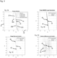
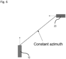
- Figs. 2 and 6 For verifying the method according to the disclosure, two different scenarios are considered in Figs. 2 and 6 , respectively. The results for the two scenarios are shown in Figs. 3 to 5 and Figs. 7 to 9 , respectively.
- the moving object 23 having a velocity of (0, -50) km/h. That is, the target object 23 crosses the vehicle 10 laterally along the y-axis 21 (see Fig. 1 ).
- Figs. 3 , 4 , 7 and 8 the respective results are depicted in a velocity coordinate system having a longitudinal axis 31 for V x and a lateral axis 33 for V y , wherein the respective velocity component is depicted in m/s. That is, the velocity of the moving object 23 is represented by a reference 35 at (0, -13,89) m/s for the first scenario in Figs. 3 and 4 .
- Fig. 3 estimation results are depicted based on three radar scans, i.e. three detections for the range rate and two detections for the position difference have been available for estimating the velocity.
- Fig. 3A single estimates are shown with respect to the reference 35 representing the "true" velocity.
- Two position difference based velocity estimates 37A, 37B are depicted together with their respective standard deviations 39A, 39B which are represented by dashed lines.
- velocity estimates 41 based on the range rate is represented as lines. This is due to the fact that the range rate, i.e. the radial velocity with respect to the vehicle, is used only for the velocity estimate 41.
- the three lines which are denoted by "rr based velocity" in Fig. 3A correspond to the three detections of the range rate and are almost identical.
- the velocity estimates 37A, 37B based on the position difference deviate strongly from the reference 35.
- Figs. 3B, 3C and 3D respective cost functions are depicted which are calculated based on the formulas provided above. Each cost function is represented by contour lines 43. In addition, a respective estimate 45 for the velocity is shown which is determined as an absolute minimum of the respective cost function. In Fig. 3B , the total NEES cost function is shown including a first contribution for the velocity profile based on the range rate and a second contribution based on the position difference. In Figs. 3C and 3D , the two contributions are depicted separately, i.e. a velocity profile cost function or range rate cost function in Fig. 3C and a position difference cost function in Fig. 3D .
- the estimates 45 for the velocity of the target object 23 are quite close to the reference 35, whereas the estimate 45 based on the range rate cost function strongly deviates from the reference 35.
- the total NEES cost function and the range rate cost function have a very small extension in the direction of V y in comparison to the position difference cost function. Therefore, the velocity estimate 45 based on the total NEES cost function has a smaller error bar than the estimate 45 based on the position difference cost function.
- the velocity estimate 45 based on the total NEES cost function is more reliable than the velocity estimate 45 based on the position difference cost function although the component V x is slightly closer to the reference 35 for the position difference cost function.
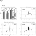
- Fig. 4 thousand Monte Carlo simulations have been performed for the first scenario assuming the same conditions as in Fig. 3 , i.e. respective three radar scans for each Monte Carlo simulation.
- Fig. 4B, 4C and 4D the respective results for the estimations 45 based on the Monte Carlo simulation are shown for the same conditions as in Fig. 3B, 3C and 3D , i.e. for the total NEES cost function ( Fig. 4B ), for the range cost function ( Fig. 4C ) and for the position difference cost function ( Fig. 4D ).
- the estimates 45 are depicted as point clouds with respect to the reference 35. As can be seen in Fig.
- the estimates 45 are generally quite close to the reference 35 for the total NEES cost function, i.e. very close to the reference in the direction of V x and quite close in an acceptable manner in the direction of V y .
- the estimates 45 strongly spread in the direction of V x for the range rate cost function as shown in Fig. 4C
- the estimate 45 show quite a large spread in the direction of V y for the position difference cost function as shown in Fig. 4D .
- the estimates 45 are most "concentrated" around the reference 35 for the total NEES cost function in Fig. 4B .
- Fig. 4A the root mean square of the error or deviation is depicted for the three types of velocity estimation, i.e. based on the total NEES cost function (depicted as bars 51), based on the range rate cost function (depicted by the bars 53), and based on the position difference cost function (depicted as bars 55).
- the term "cloud” is used as synonym for the range rate cost function in the legend of Fig. 4A .
- the respective root mean square is shown for both velocity components V x and V y , for the heading or direction of the velocity and for the magnitude or absolute value of the velocity.
- the velocity estimation based on the total NEES cost function shows the lowest root mean square of the deviations in all cases.
- the respective root mean square of the deviations (on the y-axis) is shown depending from the number of radar scans (on the x-axis) for the heading ( Fig. 5A ), for the magnitude ( Fig. 5B ), for the velocity component V x ( Fig 5C ) and for the velocity component V y ( Fig. 5D ).
- the lines 61 represent the respective root mean square of the deviations for the velocity estimates based on the total NEES cost function, wherein the lines 63 represent the root mean square of the deviations of velocity estimates based on the range rate cost function, and the lines 65 represent the root mean square of the deviation for the velocity estimates based on the position difference cost function.
- the root mean square of the deviations has the lowest value in almost all cases for the velocity estimate based on the NEES cost function. Please note the logarithmic scale on the y-axis.
- the second scenario is depicted in which the vehicle 10 and the target object 23 move perpendicular to each other with the same constant velocity, i.e. having an absolute value or magnitude of 50 km/h. Therefore, a constant azimuth angle is assumed for the target object 23 with respect to the vehicle 10.
- the velocity of vehicle 10 is (50,0) km/h
- the velocity of the target object 23 is (0, -50) km/h.
- ⁇ r 0.15 m
- ⁇ r ⁇ comp 0.05 m s .
- Single point detections are generated again from the left corner of the target object 23 for each time step.
- Fig. 7 corresponds to the results as shown in Fig. 3 for the first scenario. That is, all general explanations regarding the diagrams and the reference numbers as provided for Figs. 3 and 4 are also valid for Figs. 7 and 8 .
- the velocity of the target object 23 is represented by a reference 35 at (-13,89, -13,89) m/s which is the relative velocity with respect to the vehicle 10 for the second scenario. In other words, the velocity of the vehicle 10 is compensated for the reference 35 in Figs. 7 and 8 .
- the range rate based estimates 41 are again represented by lines.
- the velocity estimates 45 based on the total NEES cost function and based on the position difference cost function are very close to the reference 35, whereas the estimate 45 based on the range rate cost function (see Fig. 7C ) strongly deviates from the reference 35. Furthermore, the spread of the cost function is much larger for the position difference cost function than for the total NEES cost function, as can be derived from the contour lines 43 representing the cost functions. As a result, the velocity estimate 45 based on the total NEES cost function has to be regarded as more reliable than the estimate based on the position difference cost function and based on the range rate cost function respectively.
- Fig. 8 depicts the results of thousand Monte Carlo simulations assuming the same conditions as for Fig. 7 , i.e. respective estimations based on three radar scans.
- the total NEES cost function again shows the lowest spread with respect to the reference 35 for the velocity estimates 45 which are related to the second scenario as shown in Fig. 6 .
- Fig. 8A the root mean square of the error for deviation is shown again for the three types of velocity estimation, wherein the bars 41 represent the root mean square of the deviations for the NEES cost function, whereas the bars 53 represent the root mean square of the deviations for the estimates based on the range rate cost function, and the bars 55 represent the root mean square of the deviations for the estimates based on the position difference cost function.
- the term "cloud" is used as synonym for the range rate cost function in the legend of Fig. 8A .
- the estimates 45 based on the total NEES cost function show again the lowest root mean square for the deviations, i.e. for both components V x and V y of the velocity, for the heading and for the magnitude.
- the results for both scenarios verify that the method according to the disclosure improves the accuracy and the reliability of the velocity estimates. This is at least partly due to the fact that the estimates rely on the total NEES cost function which includes two contributions or sources for the velocity estimates.
Landscapes
- Engineering & Computer Science (AREA)
- Remote Sensing (AREA)
- Radar, Positioning & Navigation (AREA)
- Physics & Mathematics (AREA)
- General Physics & Mathematics (AREA)
- Computer Networks & Wireless Communication (AREA)
- Electromagnetism (AREA)
- Mathematical Physics (AREA)
- Theoretical Computer Science (AREA)
- Computational Mathematics (AREA)
- Pure & Applied Mathematics (AREA)
- Data Mining & Analysis (AREA)
- Mathematical Analysis (AREA)
- Mathematical Optimization (AREA)
- Algebra (AREA)
- Multimedia (AREA)
- Computer Vision & Pattern Recognition (AREA)
- Databases & Information Systems (AREA)
- Software Systems (AREA)
- General Engineering & Computer Science (AREA)
- Computing Systems (AREA)
- Operations Research (AREA)
- Radar Systems Or Details Thereof (AREA)
Claims (11)
- Computerimplementiertes Verfahren zum Schätzen einer Geschwindigkeit eines Objekts (23), das sich in der Umgebung eines Fahrzeugs (10) befindet, welches mit einem Sensor (13) und einer Verarbeitungseinheit (15) ausgestattet ist, wobei der Sensor (13) ausgebildet ist, Daten zum Ermitteln einer Entfernung, eines Azimutwinkels und einer Entfernungsänderung des Objekts (23) bereitzustellen,wobei das Verfahren umfasst, dass:mittels des Sensors (13) Detektionen der Entfernung, des Azimutwinkels und der Entfernungsänderung des Objekts (23) für mindestens zwei unterschiedliche Zeitpunkte erfasst werden,mittels der Verarbeitungseinheit (15):eine Kostenfunktion (43) erzeugt wird, die von einer ersten Quelle und einer zweiten Quelle abhängt,wobei die erste Quelle auf einem Entfernungsänderungs-Geschwindigkeitsprofil basiert, das von der Entfernungsänderung und dem Azimutwinkel abhängt, und wobei die erste Quelle von einer geschätzten Genauigkeit für die erste Quelle abhängt,wobei die zweite Quelle auf einer Positionsdifferenz basiert, die von der Entfernung und dem Azimutwinkel für die mindestens zwei unterschiedlichen Zeitpunkte abhängt, und wobei die zweite Quelle von einer geschätzten Genauigkeit für die zweite Quelle abhängt, undeine Geschwindigkeitsschätzung (45) für das Objekt (23) durch Minimieren der Kostenfunktion (43) ermittelt wird,wobeieine Vielzahl von Detektionen der Entfernung, des Azimutwinkels und der Entfernungsänderung für das Objekt (23) für jeden der mindestens zwei Zeitpunkte erfasst werden,eine jeweilige Standardabweichung für die Entfernung, den Azimutwinkel und die Entfernungsänderung basierend auf der Vielzahl von Detektionen geschätzt wird,das Entfernungsänderungs-Geschwindigkeitsprofil von der Vielzahl von Detektionen der Entfernungsänderung und des Azimutwinkels abhängt,die Positionsdifferenz von der Vielzahl von Detektionen der Entfernung und des Azimutwinkels für die mindestens zwei unterschiedlichen Zeitpunkte abhängt,die geschätzte Genauigkeit der ersten Quelle von der Standardabweichung der Entfernungsänderung und der Standardabweichung des Azimutwinkels abhängt,die geschätzte Genauigkeit der zweiten Quelle von der Standardabweichung der Entfernung und der Standardabweichung des Azimutwinkels abhängt,die Kostenfunktion (43) eine erste Verteilung, die mit der ersten Quelle in Beziehung steht, und eine zweite Verteilung umfasst, die mit der zweiten Quelle in Beziehung steht, unddie erste Verteilung und die zweite Verteilung jeweils eine Summe von Elementen über die Vielzahl von Detektionen umfassen, wobei jedes Element als ein normierter quadrierter Schätzfehler (NEES) für die jeweilige Detektion geschätzt wird, welcher die jeweiligen Standardabweichungen der Entfernung, des Azimutwinkels und der Entfernungsänderung umfasst.
- Verfahren nach Anspruch 1, wobei
unterschiedliche Standardabweichungen der Entfernung, des Azimutwinkels und der Entfernungsänderung für jeden der mindestens zwei Zeitpunkte und/oder für jede Detektion der Entfernung, des Azimutwinkels und der Entfernungsänderung geschätzt werden. - Verfahren nach Anspruch 1 oder 2, wobei
die Elemente der ersten Verteilung auf einer Entfernungsänderungsgleichung und der Standardabweichung der Entfernungsänderung basieren. - Verfahren nach Anspruch 1, 2 oder 3, wobei
die Elemente der zweiten Verteilung auf der Positionsdifferenz für die jeweilige Detektion und auf einer Geschwindigkeits-Kovarianzmatrix basieren, die basierend auf den Standardabweichungen der Entfernung und des Azimutwinkels sowie basierend auf einem Zeitintervall zwischen den mindestens zwei unterschiedlichen Zeitpunkten geschätzt wird, für welche die Entfernung und der Azimutwinkel mittels des Sensors (13) erfasst werden. - Verfahren nach einem der Ansprüche 1 bis 4, wobei
die Kostenfunktion (43) als ein Mittelwert der ersten Verteilung und der zweiten Verteilung erzeugt wird. - Verfahren nach einem der vorstehenden Ansprüche, wobei
eine Komponente der Geschwindigkeit geschätzt wird, indem die Ableitung der Kostenfunktion (43) bezogen auf die Geschwindigkeitskomponente gleich Null gesetzt wird. - Verfahren nach einem der vorstehenden Ansprüche, wobei
die Kostenfunktion (43) und die Geschwindigkeitsschätzung (45) unter der Annahme einer konstanten Geschwindigkeit des Objekts (23) ermittelt werden, um eine Kalman-Filter-Zustandsschätzung der Geschwindigkeit zu initialisieren. - Vorrichtung (11) zum Schätzen einer Geschwindigkeit eines Objekts (23), das sich in der Umgebung eines Fahrzeugs (10) befindet,wobei die Vorrichtung (11) umfasst:einen Sensor (13), der ausgebildet ist, Daten zum Erfassen von Detektionen einer Entfernung, eines Azimutwinkels und einer Entfernungsänderung des Objekts (23) für mindestens zwei unterschiedliche Zeitpunkte bereitzustellen, undeine Verarbeitungseinheit (15), die ausgebildet ist:eine Kostenfunktion (43) zu erzeugen, die von einer ersten Quelle und einer zweiten Quelle abhängt,wobei die erste Quelle auf einem Entfernungsänderungs-Geschwindigkeitsprofil basiert, das von der Entfernungsänderung und dem Azimutwinkel abhängt, und wobei die erste Quelle von einer geschätzten Genauigkeit für die erste Quelle abhängt,wobei die zweite Quelle auf einer Positionsdifferenz basiert, die von der Entfernung und dem Azimutwinkel für die mindestens zwei unterschiedlichen Zeitpunkte abhängt, und wobei die zweite Quelle von einer geschätzten Genauigkeit für die zweite Quelle abhängt, undeine Geschwindigkeitsschätzung (45) für das Objekt (23) durch Minimieren der Kostenfunktion (43) zu ermitteln,wobei der Sensor (13) ausgebildet ist:eine Vielzahl von Detektionen der Entfernung, des Azimutwinkels und der Entfernungsänderung für das Objekt (23) für jeden der mindestens zwei Zeitpunkte zu erfassen, undeine jeweilige Standardabweichung für die Entfernung, den Azimutwinkel und die Entfernungsänderung basierend auf der Vielzahl von Detektionen zu schätzen,wobeidas Entfernungsänderungs-Geschwindigkeitsprofil von der Vielzahl von Detektionen der Entfernungsänderung und des Azimutwinkels abhängt,die Positionsdifferenz von der Vielzahl von Detektionen der Entfernung und des Azimutwinkels für die mindestens zwei unterschiedlichen Zeitpunkte abhängt,die geschätzte Genauigkeit der ersten Quelle von der Standardabweichung der Entfernungsänderung und der Standardabweichung des Azimutwinkels abhängt,die geschätzte Genauigkeit der zweiten Quelle von der Standardabweichung der Entfernung und der Standardabweichung des Azimutwinkels abhängt,die Kostenfunkton (43) eine erste Verteilung, die mit der ersten Quelle in Beziehung steht, und eine zweite Verteilung umfasst, die mit der zweiten Quelle in Beziehung steht, unddie erste Verteilung und die zweite Verteilung jeweils eine Summe von Elementen über die Vielzahl von Detektionen umfassen, wobei jedes Element als ein normierter quadrierter Schätzfehler (NEES) für die jeweilige Detektion geschätzt wird, welcher die jeweiligen Standardabweichungen der Entfernung, des Azimutwinkels und der Entfernungsänderung umfasst.
- Vorrichtung (11) nach Anspruch 8, wobei
der Sensor (13) einen Radarsensor und/oder einen Lidar-Sensor umfasst. - Computerprogrammprodukt, das Anweisungen umfasst, die dann, wenn das Programm durch eine Vorrichtung (11) nach Anspruch 8 ausgeführt wird, bewirken, dass die Vorrichtung (11) das computerimplementierte Verfahren nach zumindest einem der Ansprüche 1 bis 7 ausführt.
- Nicht-flüchtiges computerlesbares Medium, das Anweisungen zum Ausführen des computerimplementierte Verfahrens nach zumindest einem der Ansprüche 1 bis 7 umfasst.
Priority Applications (3)
| Application Number | Priority Date | Filing Date | Title |
|---|---|---|---|
| EP21168600.1A EP4075164B1 (de) | 2021-04-15 | 2021-04-15 | Verfahren und vorrichtung zur schätzung der geschwindigkeit eines objektes |
| US17/657,567 US12366644B2 (en) | 2021-04-15 | 2022-03-31 | Method and device for estimating a velocity of an object |
| CN202210377757.7A CN115222766A (zh) | 2021-04-15 | 2022-04-12 | 估计对象速度的方法和装置 |
Applications Claiming Priority (1)
| Application Number | Priority Date | Filing Date | Title |
|---|---|---|---|
| EP21168600.1A EP4075164B1 (de) | 2021-04-15 | 2021-04-15 | Verfahren und vorrichtung zur schätzung der geschwindigkeit eines objektes |
Publications (2)
| Publication Number | Publication Date |
|---|---|
| EP4075164A1 EP4075164A1 (de) | 2022-10-19 |
| EP4075164B1 true EP4075164B1 (de) | 2025-01-08 |
Family
ID=75539185
Family Applications (1)
| Application Number | Title | Priority Date | Filing Date |
|---|---|---|---|
| EP21168600.1A Active EP4075164B1 (de) | 2021-04-15 | 2021-04-15 | Verfahren und vorrichtung zur schätzung der geschwindigkeit eines objektes |
Country Status (3)
| Country | Link |
|---|---|
| US (1) | US12366644B2 (de) |
| EP (1) | EP4075164B1 (de) |
| CN (1) | CN115222766A (de) |
Families Citing this family (2)
| Publication number | Priority date | Publication date | Assignee | Title |
|---|---|---|---|---|
| US20250244464A1 (en) * | 2024-01-30 | 2025-07-31 | Wistron Neweb Corporation | Radar system and velocity correction method thereof |
| CN119239656B (zh) * | 2024-11-12 | 2025-07-04 | 酷睿程(北京)科技有限公司 | 目标检测方法、车辆控制方法、设备、车辆、介质和芯片 |
Family Cites Families (7)
| Publication number | Priority date | Publication date | Assignee | Title |
|---|---|---|---|---|
| US7132982B2 (en) * | 1999-03-05 | 2006-11-07 | Rannock Corporation | Method and apparatus for accurate aircraft and vehicle tracking |
| DE10226508A1 (de) * | 2002-06-14 | 2004-01-08 | Dornier Gmbh | Verfahren zur Detektion sowie Geschwindigkeits- und Positionsschätzung von bewegten Objekten in SAR-Bildern |
| EP3422042B1 (de) | 2017-06-29 | 2020-03-18 | Aptiv Technologies Limited | Verfahren zur bestimmung der ausrichtung eines zielfahrzeugs |
| EP3499265B1 (de) * | 2017-12-12 | 2020-08-19 | Veoneer Sweden AB | Bestimmung des objektbewegungs- und -beschleunigungsvektors in einem fahrzeugradarsystem |
| EP3572839A1 (de) * | 2018-05-23 | 2019-11-27 | Aptiv Technologies Limited | Verfahren zur schätzung eines geschwindigkeitsausmasses eines sich bewegenden ziels in einer horizontalen ebene und radardetektionssystem |
| US10948583B2 (en) * | 2018-10-23 | 2021-03-16 | Valeo Radar Systems, Inc. | Radar track initialization |
| CA3120498C (en) * | 2018-12-14 | 2023-09-26 | Thales Canada Inc. | Vehicle odometry and motion direction determination |
-
2021
- 2021-04-15 EP EP21168600.1A patent/EP4075164B1/de active Active
-
2022
- 2022-03-31 US US17/657,567 patent/US12366644B2/en active Active
- 2022-04-12 CN CN202210377757.7A patent/CN115222766A/zh active Pending
Also Published As
| Publication number | Publication date |
|---|---|
| EP4075164A1 (de) | 2022-10-19 |
| US12366644B2 (en) | 2025-07-22 |
| US20220334238A1 (en) | 2022-10-20 |
| CN115222766A (zh) | 2022-10-21 |
Similar Documents
| Publication | Publication Date | Title |
|---|---|---|
| EP3654064B1 (de) | Vorrichtung und verfahren zur charakterisierung eines objekts auf basis von messproben von einem oder mehreren ortssensoren | |
| EP3611541B1 (de) | Verfahren zur bestimmung einer unsicherheitsschätzung einer geschätzten geschwindigkeit | |
| CN104035439B (zh) | 用多个激光雷达传感器利用扫描点追踪物体的贝叶斯网络 | |
| EP3572839A1 (de) | Verfahren zur schätzung eines geschwindigkeitsausmasses eines sich bewegenden ziels in einer horizontalen ebene und radardetektionssystem | |
| CN103308923B (zh) | 来自多个激光雷达的距离图像配准方法 | |
| US12005907B2 (en) | Method for determining position data and/or motion data of a vehicle | |
| EP3575827B1 (de) | Verfahren zur robusten schätzung der geschwindigkeit eines ziels mithilfe eines host-fahrzeugs | |
| US10527705B2 (en) | System and method for multi-sensor multi-target 3D fusion using an unbiased measurement space | |
| EP3193306B1 (de) | Verfahren und vorrichtung zum schätzen einer ausrichtung einer kamera in bezug auf eine fahrbahn | |
| EP4194885B1 (de) | Verfahren zur bestimmung des mobilitätszustands eines zielobjekts | |
| CN112154429B (zh) | 高精度地图定位方法、系统、平台及计算机可读存储介质 | |
| EP4075164B1 (de) | Verfahren und vorrichtung zur schätzung der geschwindigkeit eines objektes | |
| KR20220160881A (ko) | 다중 필터 및 센서 퓨전 기반의 차량의 위치 추정 방법 | |
| US20230036137A1 (en) | Predictive tracking apparatus, predictive tracking method, and computer-readable medium | |
| Herrmann et al. | LMB filter based tracking allowing for multiple hypotheses in object reference point association | |
| CN108872973B (zh) | 一种弹道导弹目标定轨的ekf滤波方法 | |
| KR20210062453A (ko) | 운동 정보 결정 방법 및 장치 | |
| RU198994U1 (ru) | Устройство определения факта искажения навигационного поля и идентификации помехового воздействия на приемник роботизированного беспилотного летательного аппарата | |
| EP3654065B1 (de) | Vorrichtung und verfahren zur charakterisierung eines objekts auf basis von messproben von einem oder mehreren ortssensoren | |
| US20250138147A1 (en) | Method for determining a pitch angle | |
| Sigonius | Speed and yaw rate estimation in autonomous vehicles using Doppler radar measurements | |
| KR102076721B1 (ko) | 표적 정보 제공 장치 및 그 방법 | |
| CN120611309A (zh) | 基于卡方累积均值的滑动窗口异常检测方法及系统 | |
| AU2021358654A1 (en) | A method and system for detecting the tumbling characteristics of space objects |
Legal Events
| Date | Code | Title | Description |
|---|---|---|---|
| PUAI | Public reference made under article 153(3) epc to a published international application that has entered the european phase |
Free format text: ORIGINAL CODE: 0009012 |
|
| STAA | Information on the status of an ep patent application or granted ep patent |
Free format text: STATUS: THE APPLICATION HAS BEEN PUBLISHED |
|
| AK | Designated contracting states |
Kind code of ref document: A1 Designated state(s): AL AT BE BG CH CY CZ DE DK EE ES FI FR GB GR HR HU IE IS IT LI LT LU LV MC MK MT NL NO PL PT RO RS SE SI SK SM TR |
|
| RAP3 | Party data changed (applicant data changed or rights of an application transferred) |
Owner name: APTIV TECHNOLOGIES LIMITED |
|
| STAA | Information on the status of an ep patent application or granted ep patent |
Free format text: STATUS: REQUEST FOR EXAMINATION WAS MADE |
|
| 17P | Request for examination filed |
Effective date: 20230331 |
|
| RBV | Designated contracting states (corrected) |
Designated state(s): AL AT BE BG CH CY CZ DE DK EE ES FI FR GB GR HR HU IE IS IT LI LT LU LV MC MK MT NL NO PL PT RO RS SE SI SK SM TR |
|
| RAP1 | Party data changed (applicant data changed or rights of an application transferred) |
Owner name: APTIV TECHNOLOGIES AG |
|
| RAP3 | Party data changed (applicant data changed or rights of an application transferred) |
Owner name: APTIV TECHNOLOGIES AG |
|
| GRAP | Despatch of communication of intention to grant a patent |
Free format text: ORIGINAL CODE: EPIDOSNIGR1 |
|
| STAA | Information on the status of an ep patent application or granted ep patent |
Free format text: STATUS: GRANT OF PATENT IS INTENDED |
|
| INTG | Intention to grant announced |
Effective date: 20241008 |
|
| GRAS | Grant fee paid |
Free format text: ORIGINAL CODE: EPIDOSNIGR3 |
|
| P01 | Opt-out of the competence of the unified patent court (upc) registered |
Free format text: CASE NUMBER: APP_58116/2024 Effective date: 20241024 |
|
| GRAA | (expected) grant |
Free format text: ORIGINAL CODE: 0009210 |
|
| STAA | Information on the status of an ep patent application or granted ep patent |
Free format text: STATUS: THE PATENT HAS BEEN GRANTED |
|
| AK | Designated contracting states |
Kind code of ref document: B1 Designated state(s): AL AT BE BG CH CY CZ DE DK EE ES FI FR GB GR HR HU IE IS IT LI LT LU LV MC MK MT NL NO PL PT RO RS SE SI SK SM TR |
|
| REG | Reference to a national code |
Ref country code: GB Ref legal event code: FG4D |
|
| REG | Reference to a national code |
Ref country code: CH Ref legal event code: EP |
|
| REG | Reference to a national code |
Ref country code: DE Ref legal event code: R096 Ref document number: 602021024561 Country of ref document: DE |
|
| REG | Reference to a national code |
Ref country code: IE Ref legal event code: FG4D |
|
| PGFP | Annual fee paid to national office [announced via postgrant information from national office to epo] |
Ref country code: FR Payment date: 20250314 Year of fee payment: 5 |
|
| PGFP | Annual fee paid to national office [announced via postgrant information from national office to epo] |
Ref country code: GB Payment date: 20250313 Year of fee payment: 5 |
|
| REG | Reference to a national code |
Ref country code: LT Ref legal event code: MG9D |
|
| REG | Reference to a national code |
Ref country code: NL Ref legal event code: MP Effective date: 20250108 |
|
| REG | Reference to a national code |
Ref country code: AT Ref legal event code: MK05 Ref document number: 1758673 Country of ref document: AT Kind code of ref document: T Effective date: 20250108 |
|
| PG25 | Lapsed in a contracting state [announced via postgrant information from national office to epo] |
Ref country code: NL Free format text: LAPSE BECAUSE OF FAILURE TO SUBMIT A TRANSLATION OF THE DESCRIPTION OR TO PAY THE FEE WITHIN THE PRESCRIBED TIME-LIMIT Effective date: 20250108 |
|
| PG25 | Lapsed in a contracting state [announced via postgrant information from national office to epo] |
Ref country code: RS Free format text: LAPSE BECAUSE OF FAILURE TO SUBMIT A TRANSLATION OF THE DESCRIPTION OR TO PAY THE FEE WITHIN THE PRESCRIBED TIME-LIMIT Effective date: 20250408 |
|
| PG25 | Lapsed in a contracting state [announced via postgrant information from national office to epo] |
Ref country code: FI Free format text: LAPSE BECAUSE OF FAILURE TO SUBMIT A TRANSLATION OF THE DESCRIPTION OR TO PAY THE FEE WITHIN THE PRESCRIBED TIME-LIMIT Effective date: 20250108 |
|
| PG25 | Lapsed in a contracting state [announced via postgrant information from national office to epo] |
Ref country code: PL Free format text: LAPSE BECAUSE OF FAILURE TO SUBMIT A TRANSLATION OF THE DESCRIPTION OR TO PAY THE FEE WITHIN THE PRESCRIBED TIME-LIMIT Effective date: 20250108 |
|
| PGFP | Annual fee paid to national office [announced via postgrant information from national office to epo] |
Ref country code: DE Payment date: 20250313 Year of fee payment: 5 |
|
| PG25 | Lapsed in a contracting state [announced via postgrant information from national office to epo] |
Ref country code: ES Free format text: LAPSE BECAUSE OF FAILURE TO SUBMIT A TRANSLATION OF THE DESCRIPTION OR TO PAY THE FEE WITHIN THE PRESCRIBED TIME-LIMIT Effective date: 20250108 |
|
| PG25 | Lapsed in a contracting state [announced via postgrant information from national office to epo] |
Ref country code: NO Free format text: LAPSE BECAUSE OF FAILURE TO SUBMIT A TRANSLATION OF THE DESCRIPTION OR TO PAY THE FEE WITHIN THE PRESCRIBED TIME-LIMIT Effective date: 20250408 Ref country code: IS Free format text: LAPSE BECAUSE OF FAILURE TO SUBMIT A TRANSLATION OF THE DESCRIPTION OR TO PAY THE FEE WITHIN THE PRESCRIBED TIME-LIMIT Effective date: 20250508 |
|
| PG25 | Lapsed in a contracting state [announced via postgrant information from national office to epo] |
Ref country code: HR Free format text: LAPSE BECAUSE OF FAILURE TO SUBMIT A TRANSLATION OF THE DESCRIPTION OR TO PAY THE FEE WITHIN THE PRESCRIBED TIME-LIMIT Effective date: 20250108 |
|
| PG25 | Lapsed in a contracting state [announced via postgrant information from national office to epo] |
Ref country code: LV Free format text: LAPSE BECAUSE OF FAILURE TO SUBMIT A TRANSLATION OF THE DESCRIPTION OR TO PAY THE FEE WITHIN THE PRESCRIBED TIME-LIMIT Effective date: 20250108 Ref country code: PT Free format text: LAPSE BECAUSE OF FAILURE TO SUBMIT A TRANSLATION OF THE DESCRIPTION OR TO PAY THE FEE WITHIN THE PRESCRIBED TIME-LIMIT Effective date: 20250508 |
|
| PG25 | Lapsed in a contracting state [announced via postgrant information from national office to epo] |
Ref country code: BG Free format text: LAPSE BECAUSE OF FAILURE TO SUBMIT A TRANSLATION OF THE DESCRIPTION OR TO PAY THE FEE WITHIN THE PRESCRIBED TIME-LIMIT Effective date: 20250108 Ref country code: GR Free format text: LAPSE BECAUSE OF FAILURE TO SUBMIT A TRANSLATION OF THE DESCRIPTION OR TO PAY THE FEE WITHIN THE PRESCRIBED TIME-LIMIT Effective date: 20250409 |
|
| PG25 | Lapsed in a contracting state [announced via postgrant information from national office to epo] |
Ref country code: AT Free format text: LAPSE BECAUSE OF FAILURE TO SUBMIT A TRANSLATION OF THE DESCRIPTION OR TO PAY THE FEE WITHIN THE PRESCRIBED TIME-LIMIT Effective date: 20250108 |
|
| PG25 | Lapsed in a contracting state [announced via postgrant information from national office to epo] |
Ref country code: SE Free format text: LAPSE BECAUSE OF FAILURE TO SUBMIT A TRANSLATION OF THE DESCRIPTION OR TO PAY THE FEE WITHIN THE PRESCRIBED TIME-LIMIT Effective date: 20250108 |
|
| PG25 | Lapsed in a contracting state [announced via postgrant information from national office to epo] |
Ref country code: SM Free format text: LAPSE BECAUSE OF FAILURE TO SUBMIT A TRANSLATION OF THE DESCRIPTION OR TO PAY THE FEE WITHIN THE PRESCRIBED TIME-LIMIT Effective date: 20250108 |
|
| REG | Reference to a national code |
Ref country code: DE Ref legal event code: R097 Ref document number: 602021024561 Country of ref document: DE |
|
| PG25 | Lapsed in a contracting state [announced via postgrant information from national office to epo] |
Ref country code: DK Free format text: LAPSE BECAUSE OF FAILURE TO SUBMIT A TRANSLATION OF THE DESCRIPTION OR TO PAY THE FEE WITHIN THE PRESCRIBED TIME-LIMIT Effective date: 20250108 |
|
| PG25 | Lapsed in a contracting state [announced via postgrant information from national office to epo] |
Ref country code: CZ Free format text: LAPSE BECAUSE OF FAILURE TO SUBMIT A TRANSLATION OF THE DESCRIPTION OR TO PAY THE FEE WITHIN THE PRESCRIBED TIME-LIMIT Effective date: 20250108 Ref country code: EE Free format text: LAPSE BECAUSE OF FAILURE TO SUBMIT A TRANSLATION OF THE DESCRIPTION OR TO PAY THE FEE WITHIN THE PRESCRIBED TIME-LIMIT Effective date: 20250108 |
|
| PG25 | Lapsed in a contracting state [announced via postgrant information from national office to epo] |
Ref country code: RO Free format text: LAPSE BECAUSE OF FAILURE TO SUBMIT A TRANSLATION OF THE DESCRIPTION OR TO PAY THE FEE WITHIN THE PRESCRIBED TIME-LIMIT Effective date: 20250108 |
|
| PG25 | Lapsed in a contracting state [announced via postgrant information from national office to epo] |
Ref country code: SK Free format text: LAPSE BECAUSE OF FAILURE TO SUBMIT A TRANSLATION OF THE DESCRIPTION OR TO PAY THE FEE WITHIN THE PRESCRIBED TIME-LIMIT Effective date: 20250108 |
|
| PLBE | No opposition filed within time limit |
Free format text: ORIGINAL CODE: 0009261 |
|
| STAA | Information on the status of an ep patent application or granted ep patent |
Free format text: STATUS: NO OPPOSITION FILED WITHIN TIME LIMIT |
|
| REG | Reference to a national code |
Ref country code: CH Ref legal event code: L10 Free format text: ST27 STATUS EVENT CODE: U-0-0-L10-L00 (AS PROVIDED BY THE NATIONAL OFFICE) Effective date: 20251119 |
|
| REG | Reference to a national code |
Ref country code: CH Ref legal event code: H13 Free format text: ST27 STATUS EVENT CODE: U-0-0-H10-H13 (AS PROVIDED BY THE NATIONAL OFFICE) Effective date: 20251125 |
|
| PG25 | Lapsed in a contracting state [announced via postgrant information from national office to epo] |
Ref country code: LU Free format text: LAPSE BECAUSE OF NON-PAYMENT OF DUE FEES Effective date: 20250415 |
|
| 26N | No opposition filed |
Effective date: 20251009 |