EP4075101B1 - Datensammlung und analyse-basierte vorrichtungsüberwachung - Google Patents
Datensammlung und analyse-basierte vorrichtungsüberwachung Download PDFInfo
- Publication number
- EP4075101B1 EP4075101B1 EP22168776.7A EP22168776A EP4075101B1 EP 4075101 B1 EP4075101 B1 EP 4075101B1 EP 22168776 A EP22168776 A EP 22168776A EP 4075101 B1 EP4075101 B1 EP 4075101B1
- Authority
- EP
- European Patent Office
- Prior art keywords
- monitoring data
- monitoring
- analysis
- operational status
- indication
- Prior art date
- Legal status (The legal status is an assumption and is not a legal conclusion. Google has not performed a legal analysis and makes no representation as to the accuracy of the status listed.)
- Active
Links
Images


Classifications
-
- G—PHYSICS
- G01—MEASURING; TESTING
- G01D—MEASURING NOT SPECIALLY ADAPTED FOR A SPECIFIC VARIABLE; ARRANGEMENTS FOR MEASURING TWO OR MORE VARIABLES NOT COVERED IN A SINGLE OTHER SUBCLASS; TARIFF METERING APPARATUS; MEASURING OR TESTING NOT OTHERWISE PROVIDED FOR
- G01D5/00—Mechanical means for transferring the output of a sensing member; Means for converting the output of a sensing member to another variable where the form or nature of the sensing member does not constrain the means for converting; Transducers not specially adapted for a specific variable
- G01D5/26—Mechanical means for transferring the output of a sensing member; Means for converting the output of a sensing member to another variable where the form or nature of the sensing member does not constrain the means for converting; Transducers not specially adapted for a specific variable characterised by optical transfer means, i.e. using infrared, visible, or ultraviolet light
- G01D5/32—Mechanical means for transferring the output of a sensing member; Means for converting the output of a sensing member to another variable where the form or nature of the sensing member does not constrain the means for converting; Transducers not specially adapted for a specific variable characterised by optical transfer means, i.e. using infrared, visible, or ultraviolet light with attenuation or whole or partial obturation of beams of light
- G01D5/34—Mechanical means for transferring the output of a sensing member; Means for converting the output of a sensing member to another variable where the form or nature of the sensing member does not constrain the means for converting; Transducers not specially adapted for a specific variable characterised by optical transfer means, i.e. using infrared, visible, or ultraviolet light with attenuation or whole or partial obturation of beams of light the beams of light being detected by photocells
- G01D5/353—Mechanical means for transferring the output of a sensing member; Means for converting the output of a sensing member to another variable where the form or nature of the sensing member does not constrain the means for converting; Transducers not specially adapted for a specific variable characterised by optical transfer means, i.e. using infrared, visible, or ultraviolet light with attenuation or whole or partial obturation of beams of light the beams of light being detected by photocells influencing the transmission properties of an optical fibre
-
- B—PERFORMING OPERATIONS; TRANSPORTING
- B60—VEHICLES IN GENERAL
- B60L—PROPULSION OF ELECTRICALLY-PROPELLED VEHICLES; SUPPLYING ELECTRIC POWER FOR AUXILIARY EQUIPMENT OF ELECTRICALLY-PROPELLED VEHICLES; ELECTRODYNAMIC BRAKE SYSTEMS FOR VEHICLES IN GENERAL; MAGNETIC SUSPENSION OR LEVITATION FOR VEHICLES; MONITORING OPERATING VARIABLES OF ELECTRICALLY-PROPELLED VEHICLES; ELECTRIC SAFETY DEVICES FOR ELECTRICALLY-PROPELLED VEHICLES
- B60L3/00—Electric devices on electrically-propelled vehicles for safety purposes; Monitoring operating variables, e.g. speed, deceleration or energy consumption
- B60L3/0023—Detecting, eliminating, remedying or compensating for drive train abnormalities, e.g. failures within the drive train
- B60L3/0046—Detecting, eliminating, remedying or compensating for drive train abnormalities, e.g. failures within the drive train relating to electric energy storage systems, e.g. batteries or capacitors
-
- B—PERFORMING OPERATIONS; TRANSPORTING
- B60—VEHICLES IN GENERAL
- B60L—PROPULSION OF ELECTRICALLY-PROPELLED VEHICLES; SUPPLYING ELECTRIC POWER FOR AUXILIARY EQUIPMENT OF ELECTRICALLY-PROPELLED VEHICLES; ELECTRODYNAMIC BRAKE SYSTEMS FOR VEHICLES IN GENERAL; MAGNETIC SUSPENSION OR LEVITATION FOR VEHICLES; MONITORING OPERATING VARIABLES OF ELECTRICALLY-PROPELLED VEHICLES; ELECTRIC SAFETY DEVICES FOR ELECTRICALLY-PROPELLED VEHICLES
- B60L58/00—Methods or circuit arrangements for monitoring or controlling batteries or fuel cells, specially adapted for electric vehicles
- B60L58/10—Methods or circuit arrangements for monitoring or controlling batteries or fuel cells, specially adapted for electric vehicles for monitoring or controlling batteries
-
- G—PHYSICS
- G01—MEASURING; TESTING
- G01D—MEASURING NOT SPECIALLY ADAPTED FOR A SPECIFIC VARIABLE; ARRANGEMENTS FOR MEASURING TWO OR MORE VARIABLES NOT COVERED IN A SINGLE OTHER SUBCLASS; TARIFF METERING APPARATUS; MEASURING OR TESTING NOT OTHERWISE PROVIDED FOR
- G01D21/00—Measuring or testing not otherwise provided for
-
- G—PHYSICS
- G01—MEASURING; TESTING
- G01D—MEASURING NOT SPECIALLY ADAPTED FOR A SPECIFIC VARIABLE; ARRANGEMENTS FOR MEASURING TWO OR MORE VARIABLES NOT COVERED IN A SINGLE OTHER SUBCLASS; TARIFF METERING APPARATUS; MEASURING OR TESTING NOT OTHERWISE PROVIDED FOR
- G01D5/00—Mechanical means for transferring the output of a sensing member; Means for converting the output of a sensing member to another variable where the form or nature of the sensing member does not constrain the means for converting; Transducers not specially adapted for a specific variable
- G01D5/26—Mechanical means for transferring the output of a sensing member; Means for converting the output of a sensing member to another variable where the form or nature of the sensing member does not constrain the means for converting; Transducers not specially adapted for a specific variable characterised by optical transfer means, i.e. using infrared, visible, or ultraviolet light
- G01D5/32—Mechanical means for transferring the output of a sensing member; Means for converting the output of a sensing member to another variable where the form or nature of the sensing member does not constrain the means for converting; Transducers not specially adapted for a specific variable characterised by optical transfer means, i.e. using infrared, visible, or ultraviolet light with attenuation or whole or partial obturation of beams of light
- G01D5/34—Mechanical means for transferring the output of a sensing member; Means for converting the output of a sensing member to another variable where the form or nature of the sensing member does not constrain the means for converting; Transducers not specially adapted for a specific variable characterised by optical transfer means, i.e. using infrared, visible, or ultraviolet light with attenuation or whole or partial obturation of beams of light the beams of light being detected by photocells
- G01D5/353—Mechanical means for transferring the output of a sensing member; Means for converting the output of a sensing member to another variable where the form or nature of the sensing member does not constrain the means for converting; Transducers not specially adapted for a specific variable characterised by optical transfer means, i.e. using infrared, visible, or ultraviolet light with attenuation or whole or partial obturation of beams of light the beams of light being detected by photocells influencing the transmission properties of an optical fibre
- G01D5/3537—Optical fibre sensor using a particular arrangement of the optical fibre itself
- G01D5/35374—Particular layout of the fiber
-
- H—ELECTRICITY
- H01—ELECTRIC ELEMENTS
- H01M—PROCESSES OR MEANS, e.g. BATTERIES, FOR THE DIRECT CONVERSION OF CHEMICAL ENERGY INTO ELECTRICAL ENERGY
- H01M10/00—Secondary cells; Manufacture thereof
- H01M10/42—Methods or arrangements for servicing or maintenance of secondary cells or secondary half-cells
- H01M10/425—Structural combination with electronic components, e.g. electronic circuits integrated to the outside of the casing
-
- H—ELECTRICITY
- H01—ELECTRIC ELEMENTS
- H01M—PROCESSES OR MEANS, e.g. BATTERIES, FOR THE DIRECT CONVERSION OF CHEMICAL ENERGY INTO ELECTRICAL ENERGY
- H01M10/00—Secondary cells; Manufacture thereof
- H01M10/42—Methods or arrangements for servicing or maintenance of secondary cells or secondary half-cells
- H01M10/44—Methods for charging or discharging
- H01M10/443—Methods for charging or discharging in response to temperature
-
- H—ELECTRICITY
- H01—ELECTRIC ELEMENTS
- H01M—PROCESSES OR MEANS, e.g. BATTERIES, FOR THE DIRECT CONVERSION OF CHEMICAL ENERGY INTO ELECTRICAL ENERGY
- H01M10/00—Secondary cells; Manufacture thereof
- H01M10/42—Methods or arrangements for servicing or maintenance of secondary cells or secondary half-cells
- H01M10/48—Accumulators combined with arrangements for measuring, testing or indicating the condition of cells, e.g. the level or density of the electrolyte
- H01M10/486—Accumulators combined with arrangements for measuring, testing or indicating the condition of cells, e.g. the level or density of the electrolyte for measuring temperature
-
- H—ELECTRICITY
- H01—ELECTRIC ELEMENTS
- H01M—PROCESSES OR MEANS, e.g. BATTERIES, FOR THE DIRECT CONVERSION OF CHEMICAL ENERGY INTO ELECTRICAL ENERGY
- H01M10/00—Secondary cells; Manufacture thereof
- H01M10/60—Heating or cooling; Temperature control
- H01M10/62—Heating or cooling; Temperature control specially adapted for specific applications
- H01M10/625—Vehicles
-
- H—ELECTRICITY
- H01—ELECTRIC ELEMENTS
- H01M—PROCESSES OR MEANS, e.g. BATTERIES, FOR THE DIRECT CONVERSION OF CHEMICAL ENERGY INTO ELECTRICAL ENERGY
- H01M10/00—Secondary cells; Manufacture thereof
- H01M10/60—Heating or cooling; Temperature control
- H01M10/63—Control systems
-
- B—PERFORMING OPERATIONS; TRANSPORTING
- B60—VEHICLES IN GENERAL
- B60L—PROPULSION OF ELECTRICALLY-PROPELLED VEHICLES; SUPPLYING ELECTRIC POWER FOR AUXILIARY EQUIPMENT OF ELECTRICALLY-PROPELLED VEHICLES; ELECTRODYNAMIC BRAKE SYSTEMS FOR VEHICLES IN GENERAL; MAGNETIC SUSPENSION OR LEVITATION FOR VEHICLES; MONITORING OPERATING VARIABLES OF ELECTRICALLY-PROPELLED VEHICLES; ELECTRIC SAFETY DEVICES FOR ELECTRICALLY-PROPELLED VEHICLES
- B60L2240/00—Control parameters of input or output; Target parameters
- B60L2240/40—Drive Train control parameters
- B60L2240/54—Drive Train control parameters related to batteries
-
- H—ELECTRICITY
- H01—ELECTRIC ELEMENTS
- H01M—PROCESSES OR MEANS, e.g. BATTERIES, FOR THE DIRECT CONVERSION OF CHEMICAL ENERGY INTO ELECTRICAL ENERGY
- H01M10/00—Secondary cells; Manufacture thereof
- H01M10/42—Methods or arrangements for servicing or maintenance of secondary cells or secondary half-cells
- H01M10/425—Structural combination with electronic components, e.g. electronic circuits integrated to the outside of the casing
- H01M2010/4271—Battery management systems including electronic circuits, e.g. control of current or voltage to keep battery in healthy state, cell balancing
-
- H—ELECTRICITY
- H01—ELECTRIC ELEMENTS
- H01M—PROCESSES OR MEANS, e.g. BATTERIES, FOR THE DIRECT CONVERSION OF CHEMICAL ENERGY INTO ELECTRICAL ENERGY
- H01M10/00—Secondary cells; Manufacture thereof
- H01M10/42—Methods or arrangements for servicing or maintenance of secondary cells or secondary half-cells
- H01M10/425—Structural combination with electronic components, e.g. electronic circuits integrated to the outside of the casing
- H01M2010/4278—Systems for data transfer from batteries, e.g. transfer of battery parameters to a controller, data transferred between battery controller and main controller
-
- H—ELECTRICITY
- H01—ELECTRIC ELEMENTS
- H01M—PROCESSES OR MEANS, e.g. BATTERIES, FOR THE DIRECT CONVERSION OF CHEMICAL ENERGY INTO ELECTRICAL ENERGY
- H01M2220/00—Batteries for particular applications
- H01M2220/20—Batteries in motive systems, e.g. vehicle, ship, plane
Definitions
- the systems, methods, and non-transitory computer readable media disclosed herein may address the aforementioned technical challenges by separating the monitoring data collector and the monitoring data analyzer from each other.
- the monitoring data collector may represent a dedicated device that includes the functionality of data collection.
- the monitoring data analyzer may include, but not limited to, the functionality of data processing and analysis.
- the systems, methods, and non-transitory computer readable media disclosed herein may provide for processing associated with the monitoring data collector to be performed at a location other than the electric vehicle.
- the processing may be performed by the monitoring data analyzer at a Cloud, a central office, etc.
- Processed results may be intermittently or upon completion communicated back to an electric vehicle, or to a plurality of electric vehicles.
- the systems, methods, and non-transitory computer readable media disclosed herein may utilize a processor of an electric vehicle.
- the processing performed by the monitoring data analyzer and associated with the monitoring data collector may be performed by utilizing a processor of an electric vehicle.
- a sensor may include an optical fiber-based sensing membrane as disclosed herein.
- the systems, methods, and non-transitory computer readable media disclosed herein may be utilized for data monitoring associated with an optical fiber-based sensing membrane.
- the optical fiber-based sensing membrane may include at least one optical fiber, and a flexible substrate.
- the at least one optical fiber may be integrated in the flexible substrate.
- the flexible substrate may include a thickness and a material property that are specified to obtain, via the at least one optical fiber and for a device that is contiguously engaged with a surface of the flexible substrate, includes the flexible substrate embedded in the device, or includes the surface of the flexible substrate at a predetermined distance from the device, a thermal and/or a mechanical property associated with the device. Examples of mechanical properties may include strain, vibration, and other such properties.
- the elements of the systems, methods, and non-transitory computer readable media disclosed herein may be any combination of hardware and programming to implement the functionalities of the respective elements.
- the combinations of hardware and programming may be implemented in a number of different ways.
- the programming for the elements may be processor executable instructions stored on a non-transitory machine-readable storage medium and the hardware for the elements may include a processing resource to execute those instructions.
- a computing device implementing such elements may include the machine-readable storage medium storing the instructions and the processing resource to execute the instructions, or the machine-readable storage medium may be separately stored and accessible by the computing device and the processing resource.
- some elements may be implemented in circuitry.
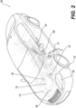
- the sensing membrane 102 may include a generally planar configuration.
- the sensing membrane 102 may include a planar configuration to match a configuration of a surface of the battery pack 104.
- the flexibility of the sensing membrane 102 may facilitate conformance of the sensing membrane 102 to variations in the surface of the battery pack 104.
- the device controller 162 may control, based on the indication of the operational status of the device 160, the operation of the device 160 to disengage a flow of electricity to and/or from the device 160.
- the monitoring data collector 152 may forward, via a Wi-Fi signal, the monitoring data 156 to the monitoring data analyzer 154 that is remote from the monitoring data collector 152.
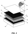
- Figure 3 illustrates a diagrammatic view illustrating the optical fiber-based sensing membrane 102 in use, according to an example of the present disclosure.
- the sensing membrane 102 may be approximately 0.5 mm, to thus minimize integration challenges with respect to the device being monitored for thermal and/or strain variations, and/or vibrations.
- the optical fibers embedded in the sensing membrane 102 may be on the order of 0.25 mm in thickness.
- such optical fibers may be treated after the sensing membrane is assembled, for example, by a combined action of pressure and temperature above the melting point of the optical fiber coating while the sensing membrane material is unaffected.
- the overall thickness of 0.5 mm may thus add minimal thickness associated with the battery pack 104.
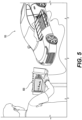
- Figure 4 illustrates a diagrammatic view illustrating a user-interface display associated with the monitoring system 100, according to an example of the present disclosure.
- Figure 5 illustrates a diagrammatic view illustrating a monitoring display associated with the monitoring system 100, according to an example of the present disclosure.
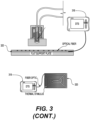
- the monitoring data collector 152 may include an optical time-domain reflectometer (OTDR) to determine temperature and/or strain associated with the device 160.
- the device may include the battery pack 104.
- the OTDR may represent an optoelectronic instrument used to characterize an optical fiber, for example, of the sensing membrane 102.
- the OTDR may inject a series of optical pulses into an optical fiber under test (e.g., an optical fiber of the sensing membrane 102). Based on the injected optical pulses, the OTDR may extract, from the same end of the optical fiber in which the optical pulses are injected, light that is scattered or reflected back from points along the optical fiber.
- a device 500 which may be an OTDR or another type of display device, may be operatively connected to the battery pack 104 to measure and/or display an operational temperature associated with one, a selected few, or all battery cells of the battery pack 104.
- monitoring data 156 may be sent from the monitoring data collector 152 to the monitoring data analyzer 154.
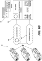
- the monitoring data analyzer 154 may be implemented, for example, in a Cloud environment 600 to perform analytics on the monitoring data 156.
- the monitoring data 156 may be sent to the Cloud environment 600, and/or to an enterprise private Cloud 602 for additional security.
- analytics may be performed at 604 with respect to an operational status of the battery pack 104 to generate insights 606 such as battery temperature, battery remaining life, operational condition (e.g., proper, improper, etc.), etc.
- the insights 606 may be displayed in a display, such as the display 404 of Figure 4 .
- battery remaining life may be determined based on the measured voltage of the battery pack 104, and a coulomb counter that measures the current taken or delivered to the battery pack 104. Knowing the battery chemistry and behavior, the operational condition and health of the battery pack 104 may be determined based on the sensor membrane 102 and other inputs.
- the monitoring data 156 may be uploaded to the Cloud in real-time (e.g., as any change in data occurs), or at pre-set intervals (e.g., every 2 seconds, 10 seconds, 30 seconds, etc.). In this regard, processing resources in the Cloud may also be conserved.
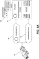
- Figure 6B illustrates Cloud and analytics to illustrate operation of the monitoring system 100, with respect to multiple vehicles, according to an example of the present disclosure.
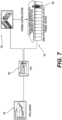
- a thermal control system 702 may control operation of the battery cells of the battery pack 104, for example, by disconnecting power to/from a specified battery cell (e.g., battery cell 704) that may be identified as a cell that may potentially experience an anomaly (e.g., high temperature, failure, etc.).
- a specified battery cell e.g., battery cell 704
- an anomaly e.g., high temperature, failure, etc.
- Figure 8 illustrates distributed data processing to illustrate operation of the monitoring system 100, according to an example of the present disclosure.
- distributed data processing with respect to the monitoring system 100 may be implemented to include optics 802, data sampling 804, and OTDR acquisition 806, which are part of the monitoring data collector 152.
- the optics 802 may include a laser to inject a series of optical pulses into an optical fiber under test (e.g., an optical fiber of the sensing membrane 102), associated analog-to-digital converter hardware, and related components.
- the data sampling 804 may include pulse generation and collection of analog-to-digital converter samples.
- the OTDR acquisition 806 may include linear buffer averaging, and a linear buffer to log buffer.
- the distributed data processing with respect to the monitoring system 100 may be implemented to include OTDR analysis 808 and temperature analysis 810, which are part of the monitoring data analyzer 154.
- the OTDR analysis 808 may include optical event detection with respect to the optical fiber under test (e.g., an optical fiber of the sensing membrane 102).
- the temperature analysis 810 may include temperature result generation, and battery and sensing membrane logic application.
- An example of the battery and sensing membrane logic application may include determining the temperature and decreasing the battery charging, inhibit charging, or reducing current drawn from the battery.
- a single OTDR acquisition 806 may be performed for a corresponding OTDR analysis 808 and the temperature analysis 810.
- a plurality of OTDR acquisitions may be performed for a single OTDR analysis 808 and temperature analysis 810 for all of the plurality of OTDR acquisitions.
- processing resources may be conserved with respect to multiple OTDR acquisitions.
- an OTDR analysis 808 and temperature analysis 810 may be performed for a plurality of OTDR acquisitions that include a specified number of acquisitions, or a number of acquisitions performed within a specified time interval, to determine trends associated with the OTDR acquisitions.
- the separation of the OTDR acquisition 806 from the OTDR analysis 808 and the temperature analysis 810 may add additional security to monitoring of thermal events associated with the battery pack 104. For example, in the event of damage to one or more acquisition features of the monitoring system 100, the monitoring data analyzer 154 may still continue to process monitoring data 156 collected by the monitoring data collector 152.
- the separation of the OTDR acquisition 806 from the OTDR analysis 808 and the temperature analysis 810 may enable the collection of the monitoring data 156 from a plurality of vehicles.
- the monitoring data 156 may be collected from several vehicles for performance on analysis to determine trends, anomalies, etc., associated with operation of the battery pack 104.
- a status of a battery pack 104 on a specified vehicle indicates a potential anomaly due to a particular event
- a notification of such an event may be relayed to other vehicles to prevent the occurrence of the anomaly in the other vehicles.
- the separation may alleviate the analysis load from the vehicle, and thus result in faster data analysis.
- a remote analysis device for the OTDR analysis 808 may also utilize a solution such as the VIAVI NITRO BI solution to analyze large datasets to reveal trends.
- the monitoring data analyzer 154 may process the monitoring data 156 collected by the monitoring data collector 152 to generate a device thermal model 158.
- the device thermal model 158 may be may be generated from various parameters such as interior/exterior temperature, vehicle and/or battery size, vehicle and/or battery type, vehicle speed, vehicle acceleration, altitude, vehicle and/or battery age, etc.
- the device thermal model 158 may be implemented based on machine learning (ML), artificial intelligence (Al), and other such techniques to generate a comprehensive model associated with the device 160, such as the battery pack 104.
- the monitoring data 156 may be used to continuously update the device thermal model 158, as well as to utilize the device thermal model 158 to predict trends and anomalies associated with the device 160.
- the separation of the monitoring data collector 152 and the monitoring data analyzer 154, and implementation of the monitoring data analyzer 154 external to a vehicle may enable utilization of virtually unlimited processing resources, compared to processing resources provided on a vehicle.
- the monitoring data collector 152 may communicate with the monitoring data analyzer 154, and vice-versa, using, for example, Wi-Fi, Long Term Evolution (LTE), cellular generally, and other such protocols.
- the type of communication interface may be selected based on cost tradeoffs versus range and bandwidth requirements.
- the monitoring data analyzer 154 may communicate an operational status 164 of the battery pack 104 with the monitoring data collector 152 or another system of the vehicle 150.
- the operational status 164 of the battery back 104 may be communicated with the monitoring data collector 152 or a central control unit of the vehicle 150.
- the monitoring data collector 152 or the central control unit may generate an audio, visual, vibration, or another type of notification to alert a user of the vehicle 150 of the need to perform maintenance or other activities on the vehicle 150.
- the operational status 164 of the battery pack 104 may include various parameters such as remaining battery life, battery temperature, battery operational status, etc.
- the operational status 164 of the battery pack 104 may be determined, for example, by utilizing AI and ML algorithms to correlate monitoring data 156 from a plurality of vehicles to determine trends that may be used to determine a value associated with the aforementioned parameters. For example, the status of the battery pack 104 to generate alarms/notifications may be determined based on thresholds for temperature of the battery pack 104, and determining, based on the thresholds, whether the battery pack 104 can still be used or the usage of the battery pack 104 may need to be modified based on a measured temperature. Since the measurement with the sensing membrane 102 is distributed, only parts of the battery pack 104 may need for usage to be adjusted if the temperatures are too high.
- a plurality of thresholds may be specified to perform different adjustments to the battery pack 104 (e.g., threshold-1 ⁇ region temperature ⁇ threshold-2, reduce battery pack usage for corresponding region by 10%, threshold-2 ⁇ region temperature ⁇ threshold-3, reduce battery pack usage for corresponding region by 20% (where threshold-2 is greater than threshold-1), threshold-2 ⁇ region temperature ⁇ threshold-3, shut down corresponding region of battery pack (where threshold-3 is greater than threshold-2), etc.).
- the separation of the collection functionality implemented by the OTDR acquisition 806, and the analysis functionality implemented by the OTDR analysis 808 and temperature analysis 810 may be used to combine other types of analysis related to the vehicle 150.
- the monitoring data 156 with respect to the battery pack 104, as well as other types of monitoring data associated with other systems and/or components of the vehicle 150 may be combined for analysis by the monitoring data analyzer 154.
- the monitoring data analyzer 154 may perform analytics on monitoring data related, for example, to vehicle speed, vehicle and/or battery temperature, time, pressure, altitude, etc., from several vehicle systems and/or components, to perform analytics on all of the vehicle systems and/or components.
- the results generated by the monitoring data analyzer 154 may be applied to various other systems and/or components of the vehicle 150.
- battery pack monitoring data 156 such as thermal, pressure, current, charge state, etc., may be analyzed with respect to the analysis functionality implemented by the OTDR analysis 808 and temperature analysis 810 (e.g., the monitoring data analyzer 154).
- Figure 9 illustrates disaggregated hardware considerations to illustrate operation of the monitoring system 100, according to an example of the present disclosure.
- various hardware elements may be utilized as shown to implement the monitoring data collector 152.
- specific calibration may be performed for each product.
- considerations may include serial data rate, multiple pins, etc.
- considerations may include whether a signal is fast/weak and an associated sampling resolution.
- considerations may include whether a signal is fast/weak, etc.
- the separation at 1000, 1002, and 1004 may respectively represent a relatively low level separation, a relatively medium level separation, and a relatively high level separation, where the collection functionality may be performed by the components above the horizontal lines at 1000, 1002, and 1004 in the orientation of Figure 10 , and the analysis functionality may be performed by the components below the horizontal lines at 1000, 1002, and 1004.
- the separation at 1000 may separate the collection functionality with respect to DTS temperature measurement.
- the separation at 1002 may separate the collection functionality with respect to DTS temperature measurement, and OTDR measurements.
- the separation at 1004 may separate the collection functionality with respect to DTS temperature measurement, the OTDR measurements, and other components as shown in Figure 10 .
- the OTDR acquisition 806 e.g., the monitoring data collector 152
- the analysis functionality implemented by the OTDR analysis 808 and temperature analysis 810 e.g., the monitoring data analyzer 154
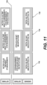
- these functionalities may be separated as shown at 1100, with different implementation options being listed at columns 1102, 1104, and 1106.
- the option at 1102 may separate the collection functionality with respect to DTS temperature measurement.
- the option at 1104 may separate the collection functionality with respect to DTS temperature measurement, and OTDR measurements.
- the option at 1106 may separate the collection functionality with respect to DTS temperature measurement, the OTDR measurements, and other components as shown in Figure 11 .
- the software may be executed on separate modules or processing subsystems. This functionality may minimize the processing power to what is needed in each software module. It also allows a software module to be moved to various pieces of hardware that may not be directly tied to the physical hardware in the vehicle.
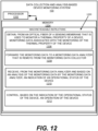
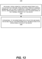
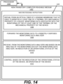
- Figures 12-14 respectively illustrate an example block diagram 1200, a flowchart of an example method 1300, and a further example block diagram 1400 for data collection and analysis-based device monitoring, according to examples.
- the block diagram 1200, the method 1300, and the block diagram 1400 may be implemented on the system 100 described above with reference to Figures 1A and 1B by way of example and not of limitation.
- the block diagram 1200, the method 1300, and the block diagram 1400 may be practiced in other system.
- Figure 12 shows hardware of the system 100 that may execute the instructions of the block diagram 1200.
- the hardware may include a processor 1202, and a memory 1204 storing machine readable instructions that when executed by the processor cause the processor to perform the instructions of the block diagram 1200.
- the processor 1202 of Figure 12 and/or the processor 1404 of Figure 14 may include a single or multiple processors or other hardware processing circuit, to execute the methods, functions and other processes described herein. These methods, functions and other processes may be embodied as machine readable instructions stored on a computer readable medium, which may be non-transitory (e.g., the non-transitory computer readable medium 1402 of Figure 14 ), such as hardware storage devices (e.g., RAM (random access memory), ROM (read only memory), EPROM (erasable, programmable ROM), EEPROM (electrically erasable, programmable ROM), hard drives, and flash memory).
- the memory 1204 may include a RAM, where the machine readable instructions and data for a processor may reside during runtime.
- the memory 1204 may include instructions 1206 to obtain, from an optical fiber of a sensing membrane 102 that is used to monitor a thermal property of a device 160, monitoring data 156 associated with the monitoring of the thermal property of the device 160.
- the processor 1202 may fetch, decode, and execute the instructions 1212 to control, based on the indication of the operational status of the device 160, an operation of the device 160.
- the method may include forwarding, to the monitoring data collector 152 and based on an analysis of the monitoring data 156, an indication of an operational status 164 of the device 160.
- the non-transitory computer readable medium 1402 may include instructions 1406 to obtain, from an optical fiber of a sensing membrane 102 that is used to monitor at least one of a thermal or a mechanical property of a device 160, monitoring data 156 associated with the monitoring of the at least one of the thermal or the mechanical property of the device 160.
Landscapes
- Engineering & Computer Science (AREA)
- General Chemical & Material Sciences (AREA)
- Manufacturing & Machinery (AREA)
- Chemical & Material Sciences (AREA)
- Chemical Kinetics & Catalysis (AREA)
- Electrochemistry (AREA)
- Power Engineering (AREA)
- Mechanical Engineering (AREA)
- Sustainable Development (AREA)
- Transportation (AREA)
- Sustainable Energy (AREA)
- Life Sciences & Earth Sciences (AREA)
- Physics & Mathematics (AREA)
- General Physics & Mathematics (AREA)
- Microelectronics & Electronic Packaging (AREA)
- Automation & Control Theory (AREA)
- Secondary Cells (AREA)
- Investigating Or Analyzing Materials Using Thermal Means (AREA)
Claims (15)
- Ein Datensammlungs- und analysebasiertes Vorrichtungsüberwachungssystem (100), beinhaltend:mindestens einen Hardwareprozessor (1202);einen Überwachungsdatensammler (152), der durch den mindestens einen Hardwareprozessor ausgeführt wird, der für Folgendes angepasst ist:Erhalten, von einer Glasfaser einer Tastmembran (102), die verwendet wird, um eine thermische Eigenschaft einer Vorrichtung (104) zu überwachen, von Überwachungsdaten, die mit dem Überwachen der thermischen Eigenschaft der Vorrichtung (104) assoziiert sind,Weiterleiten der Überwachungsdaten an einen Überwachungsdatenanalysator (154), der physisch von dem Überwachungsdatensammler (152) entfernt ist, und Empfangen, von dem Überwachungsdatenanalysator (154) und basierend auf einer Analyse der Überwachungsdaten durch den Überwachungsdatenanalysator (154), eines Hinweises auf einen Betriebszustand der Vorrichtung (104); undeine Vorrichtungssteuerung (162), die durch den mindestens einen Hardwareprozessor (1202) ausgeführt wird, für Folgendes:
Steuern, basierend auf dem Hinweis auf den Betriebszustand der Vorrichtung (104), eines Betriebs der Vorrichtung (104). - Datensammlungs- und analysebasiertes Vorrichtungsüberwachungssystem (100) gemäß Anspruch 1, wobei die Vorrichtung ein Batteriepack (104) eines Elektrofahrzeugs (150) umfasst.
- Datensammlungs- und analysebasiertes Vorrichtungsüberwachungssystem (100) gemäß Anspruch 1, wobei der Überwachungsdatenanalysator (154) in einer Cloud implementiert ist.
- Datensammlungs- und analysebasiertes Vorrichtungsüberwachungssystem (100) gemäß Anspruch 1, wobei die Tastmembran (102) eine im Allgemeinen ebene Konfiguration umfasst.
- Datensammlungs- und analysebasiertes Vorrichtungsüberwachungssystem (100) gemäß Anspruch 1, wobei die Vorrichtungssteuerung (162) durch den mindestens einen Hardwareprozessor (1202) ausgeführt wird, um basierend auf dem Hinweis auf den Betriebszustand der Vorrichtung (104) den Betrieb der Vorrichtung (104) durch Folgendes zu steuern:Steuern, basierend auf dem Hinweis auf den Betriebszustand der Vorrichtung (104), des Betriebs der Vorrichtung (104), um einen Elektrizitätsfluss mindestens eines von zu oder von der Vorrichtung (104) auszuschalten; oderErzeugen, basierend auf dem Hinweis auf den Betriebszustand der Vorrichtung (104), einer Benachrichtigung, die mit dem Betriebszustand der Vorrichtung (104) assoziiert ist.
- Datensammlungs- und analysebasiertes Vorrichtungsüberwachungssystem (100) gemäß Anspruch 1, wobei der Überwachungsdatensammler (152) durch den mindestens einen Hardwareprozessor (1202) ausgeführt wird, um die Überwachungsdaten an den Überwachungsdatenanalysator (154), der entfernt von dem Überwachungsdatensammler (152) ist, durch Folgendes weiterzuleiten:Weiterleiten, über ein Wi-Fi-Signal, der Überwachungsdaten an den Überwachungsdatenanalysator (154), der entfernt von dem Überwachungsdatensammler (152) ist; oderWeiterleiten, über ein Mobilfunksignal, der Überwachungsdaten an den Überwachungsdatenanalysator (154), der entfernt von dem Überwachungsdatensammler (152) ist.
- Ein Verfahren zur Datensammlung und analysebasierten Vorrichtungsüberwachung, wobei das Verfahren Folgendes beinhaltet:Empfangen, durch mindestens einen Hardwareprozessor (1202), von einem physisch entfernt angeordneten Überwachungsdatensammler (152), der von einer Glasfaser einer Tastmembran (102), die verwendet wird, um eine thermische Eigenschaft einer Vorrichtung (104) zu überwachen, Überwachungsdaten erhält, die mit dem Überwachen der thermischen Eigenschaft der Vorrichtung (104) assoziiert sind; undWeiterleiten, durch den mindestens einen Hardwareprozessor (1202), an den Überwachungsdatensammler (152) und basierend auf einer Analyse der Überwachungsdaten, eines Hinweises auf einen Betriebszustand der Vorrichtung (104), wobei der Hinweis auf den Betriebszustand der Vorrichtung (104) verwendet werden soll, um einen Betrieb der Vorrichtung (104) zu steuern.
- Verfahren zur Datensammlung und analysebasierten Vorrichtungsüberwachung gemäß Anspruch 7, wobei die Vorrichtung ein Batteriepack (104) eines Elektrofahrzeugs (150) umfasst.
- Verfahren zur Datensammlung und analysebasierten Vorrichtungsüberwachung gemäß Anspruch 7, wobei der Überwachungsdatensammler (152) in einem Elektrofahrzeug (150) implementiert ist.
- Verfahren zur Datensammlung und analysebasierten Vorrichtungsüberwachung gemäß Anspruch 7, wobei das Weiterleiten, durch den mindestens einen Hardwareprozessor (1202), an den Überwachungsdatensammler (152) und basierend auf der Analyse der Überwachungsdaten, des Hinweises auf den Betriebszustand der Vorrichtung (104) ferner Folgendes beinhaltet:Weiterleiten, durch den mindestens einen Hardwareprozessor (1202) und über ein Wi-Fi-Signal, an den Überwachungsdatensammler (152) und basierend auf der Analyse der Überwachungsdaten, des Hinweises auf den Betriebszustand der Vorrichtung (104); oderWeiterleiten, durch den mindestens einen Hardwareprozessor (1202) und über ein Mobilfunksignal, an den Überwachungsdatensammler (152) und basierend auf der Analyse der Überwachungsdaten, des Hinweises auf den Betriebszustand der Vorrichtung (104).
- Ein nicht transitorisches, computerlesbares Medium, das darauf gespeichert maschinenlesbare Anweisungen aufweist, wobei die maschinenlesbaren Anweisungen, wenn sie durch den mindestens einen Hardwareprozessor (1202) ausgeführt werden, bewirken, dass der mindestens eine Hardwareprozessor (1202) Folgendes vornimmt:Erhalten, von einer Glasfaser einer Tastmembran (102), die verwendet wird, um mindestens eine von einer thermischen oder einer mechanischen Eigenschaft einer Vorrichtung (104) zu überwachen, von Überwachungsdaten, die mit dem Überwachen der mindestens einen von der thermischen oder der mechanischen Eigenschaft der Vorrichtung (104) assoziiert sind;Weiterleiten der Überwachungsdaten an einen physisch entfernt angeordneten Überwachungsdatenanalysator (154);Empfangen, von dem Überwachungsdatenanalysator (154) und basierend auf einer Analyse der Überwachungsdaten durch den Überwachungsdatenanalysator (154), eines Hinweises auf einen Betriebszustand der Vorrichtung (104); undSteuern, basierend auf dem Hinweis auf den Betriebszustand der Vorrichtung (104), eines Betriebs der Vorrichtung (104).
- Nicht transitorisches computerlesbares Medium gemäß Anspruch 11, wobei die Vorrichtung ein Batteriepack (104) eines Elektrofahrzeugs (150) umfasst und/oder der Überwachungsdatenanalysator (154) in einer Cloud implementiert ist.
- Nicht transitorisches, computerlesbares Medium gemäß Anspruch 11, wobei die Tastmembran (102) eine im Allgemeinen ebene Konfiguration umfasst.
- Nicht transitorisches, computerlesbares Medium gemäß Anspruch 11, wobei die maschinenlesbaren Anweisungen zur Steuerung, basierend auf dem Hinweis auf den Betriebszustand der Vorrichtung (104), des Betriebs der Vorrichtung (104), wenn sie durch den mindestens einen Hardwareprozessor (1202) ausgeführt werden, ferner bewirken, dass der mindestens eine Hardwareprozessor (1202) Folgendes vornimmt:Steuern, basierend auf dem Hinweis auf den Betriebszustand der Vorrichtung (104), des Betriebs der Vorrichtung (104), um einen Elektrizitätsfluss mindestens eines von zu oder von der Vorrichtung (104) auszuschalten; oderErzeugen, basierend auf dem Hinweis auf den Betriebszustand der Vorrichtung (104), einer Benachrichtigung, die mit dem Betriebszustand der Vorrichtung (104) assoziiert ist.
- Nicht transitorisches, computerlesbares Medium gemäß Anspruch 11, wobei die maschinenlesbaren Anweisungen zum Weiterleiten der Überwachungsdaten an den entfernt angeordneten Überwachungsdatenanalysator, wenn sie durch den mindestens einen Hardwareprozessor ausgeführt werden, ferner bewirken, dass der mindestens eine Hardwareprozessor Folgendes vornimmt::
Weiterleiten, über ein Wi-Fi- oder ein Mobilfunksignal, der Überwachungsdaten an den entfernt angeordneten Überwachungsdatenanalysator.
Priority Applications (1)
| Application Number | Priority Date | Filing Date | Title |
|---|---|---|---|
| EP24177475.1A EP4401192A3 (de) | 2021-04-16 | 2022-04-19 | Datensammlungs- und analysebasierte vorrichtungsüberwachung |
Applications Claiming Priority (4)
| Application Number | Priority Date | Filing Date | Title |
|---|---|---|---|
| EP21305506 | 2021-04-16 | ||
| EP21305505 | 2021-04-16 | ||
| EP21186792 | 2021-07-20 | ||
| US17/563,888 US20220332217A1 (en) | 2021-04-16 | 2021-12-28 | Data collection and analysis-based device monitoring |
Related Child Applications (2)
| Application Number | Title | Priority Date | Filing Date |
|---|---|---|---|
| EP24177475.1A Division EP4401192A3 (de) | 2021-04-16 | 2022-04-19 | Datensammlungs- und analysebasierte vorrichtungsüberwachung |
| EP24177475.1A Division-Into EP4401192A3 (de) | 2021-04-16 | 2022-04-19 | Datensammlungs- und analysebasierte vorrichtungsüberwachung |
Publications (2)
| Publication Number | Publication Date |
|---|---|
| EP4075101A1 EP4075101A1 (de) | 2022-10-19 |
| EP4075101B1 true EP4075101B1 (de) | 2024-07-03 |
Family
ID=81327031
Family Applications (2)
| Application Number | Title | Priority Date | Filing Date |
|---|---|---|---|
| EP22168776.7A Active EP4075101B1 (de) | 2021-04-16 | 2022-04-19 | Datensammlung und analyse-basierte vorrichtungsüberwachung |
| EP24177475.1A Pending EP4401192A3 (de) | 2021-04-16 | 2022-04-19 | Datensammlungs- und analysebasierte vorrichtungsüberwachung |
Family Applications After (1)
| Application Number | Title | Priority Date | Filing Date |
|---|---|---|---|
| EP24177475.1A Pending EP4401192A3 (de) | 2021-04-16 | 2022-04-19 | Datensammlungs- und analysebasierte vorrichtungsüberwachung |
Country Status (2)
| Country | Link |
|---|---|
| EP (2) | EP4075101B1 (de) |
| CN (1) | CN115214421B (de) |
Families Citing this family (1)
| Publication number | Priority date | Publication date | Assignee | Title |
|---|---|---|---|---|
| CN118841656B (zh) * | 2024-06-20 | 2025-03-25 | 江西江铼新材料科技有限公司 | 智能控制下的磷酸铁锂电池材料分离与提纯系统及方法 |
Family Cites Families (12)
| Publication number | Priority date | Publication date | Assignee | Title |
|---|---|---|---|---|
| US9209494B2 (en) * | 2012-09-28 | 2015-12-08 | Palo Alto Research Center Incorporated | Monitoring/managing electrochemical energy device using detected intercalation stage changes |
| US9583796B2 (en) * | 2014-04-01 | 2017-02-28 | Palo Alto Research Center Incorporated | Method for monitoring/managing electrochemical energy device by detecting intercalation stage changes |
| US9677916B2 (en) * | 2014-07-15 | 2017-06-13 | Palo Alto Research Center Incorporated | Energy system monitoring |
| US10861682B2 (en) * | 2014-07-31 | 2020-12-08 | iSenseCloud, Inc. | Test wafer with optical fiber with Bragg Grating sensors |
| US10854932B2 (en) * | 2015-07-28 | 2020-12-01 | Palo Alto Research Center Incorporated | Method and system to separate optically measured coupled parameters |
| US11420532B2 (en) * | 2015-11-11 | 2022-08-23 | Rivian Ip Holdings, Llc | Systems and methods for monitoring and enhancing utilization of batteries for electric vehicles based on vehicle usage |
| US10589629B2 (en) * | 2016-09-14 | 2020-03-17 | GM Global Technology Operations LLC | Electrochemical device sensor and method of making and using the same |
| US20180321325A1 (en) * | 2017-05-08 | 2018-11-08 | Aleksandra Fortier | Embedded Sensors for In-Situ Cell Monitoring of Batteries |
| US10857889B2 (en) * | 2017-10-04 | 2020-12-08 | Nio Usa, Inc. | Highly-integrated fail operational e-powertrain for autonomous driving application |
| CN108749607A (zh) * | 2018-05-23 | 2018-11-06 | 清华大学深圳研究生院 | 一种基于云计算的电动汽车动力电池管理和监控系统 |
| CN109459702B (zh) * | 2018-11-09 | 2021-11-12 | 爱驰汽车有限公司 | 基于车联网的电池状态分析方法及装置 |
| CN112103576B (zh) * | 2020-09-21 | 2021-06-22 | 北京理工大学 | 一种智能电池 |
-
2022
- 2022-04-18 CN CN202210405178.9A patent/CN115214421B/zh active Active
- 2022-04-19 EP EP22168776.7A patent/EP4075101B1/de active Active
- 2022-04-19 EP EP24177475.1A patent/EP4401192A3/de active Pending
Also Published As
| Publication number | Publication date |
|---|---|
| EP4401192A3 (de) | 2024-09-04 |
| CN115214421A (zh) | 2022-10-21 |
| EP4401192A2 (de) | 2024-07-17 |
| CN115214421B (zh) | 2025-10-10 |
| EP4075101A1 (de) | 2022-10-19 |
Similar Documents
| Publication | Publication Date | Title |
|---|---|---|
| US11022501B2 (en) | Apparatus and method for measuring temperature of batteries and internal battery components | |
| CN111133325A (zh) | 用于确定电池的充电状态的系统和方法 | |
| US20130283099A1 (en) | System and method for tesing stability of server | |
| CN101499544A (zh) | 电池装置、保护电路、温度监控方法、温度传感器布置方法 | |
| RU2454632C2 (ru) | Способ контроля состояния силоизмерительного устройства, силоизмерительное устройство и силоизмерительный модуль | |
| KR102133385B1 (ko) | 유도전동기 실시간 진단 서비스를 제공하는 인공지능장치 및 그 동작방법 | |
| US10841125B2 (en) | Method for transmitting data from a sensor | |
| US10451685B2 (en) | Secondary battery system and method for identifying abnormality of secondary battery system | |
| KR102265423B1 (ko) | 초음파센서를 이용한 배터리 안전상태 진단 모니터링 시스템 | |
| KR20210012200A (ko) | 환경시험 장비의 성능이상 감지장치를 이용한 유지관리 시스템 및 그 제어방법 | |
| EP4075101B1 (de) | Datensammlung und analyse-basierte vorrichtungsüberwachung | |
| CN110119128A (zh) | 一种用于实验室用电设备的监控管理系统 | |
| US20220332217A1 (en) | Data collection and analysis-based device monitoring | |
| CN117691224A (zh) | 电池热失控预警方法、系统、电子设备及存储介质 | |
| KR102874967B1 (ko) | 배터리 관리 장치 및 이를 포함하는 배터리 검사 시스템 | |
| Minn et al. | DronLomaly: Runtime Log-based Anomaly Detector for DJI Drones | |
| JP2024529852A (ja) | 締め具、監視方法およびシステム | |
| WO2018117164A1 (ja) | プラント設備診断システム | |
| US6693560B2 (en) | Submarine mast autonomous controller and method | |
| US20250372737A1 (en) | Management of measurement data relating to an energy storage system | |
| US12420946B2 (en) | Dynamic air data probe prognostics health monitoring coordinator | |
| EP4224172B1 (de) | Dynamisches mehrstufiges luftdatensondenprognostisches gesundheitsüberwachungsmanagement | |
| EP4224171B1 (de) | Randvorrichtung zur prognose der gesundheitsüberwachung einer dynamischen luftdatensonde | |
| KR101559342B1 (ko) | 변전설비의 트러블 예방 시스템 | |
| US20230251283A1 (en) | Dynamic multi-stage air data probe prognostics health monitoring system |
Legal Events
| Date | Code | Title | Description |
|---|---|---|---|
| PUAI | Public reference made under article 153(3) epc to a published international application that has entered the european phase |
Free format text: ORIGINAL CODE: 0009012 |
|
| STAA | Information on the status of an ep patent application or granted ep patent |
Free format text: STATUS: THE APPLICATION HAS BEEN PUBLISHED |
|
| AK | Designated contracting states |
Kind code of ref document: A1 Designated state(s): AL AT BE BG CH CY CZ DE DK EE ES FI FR GB GR HR HU IE IS IT LI LT LU LV MC MK MT NL NO PL PT RO RS SE SI SK SM TR |
|
| STAA | Information on the status of an ep patent application or granted ep patent |
Free format text: STATUS: REQUEST FOR EXAMINATION WAS MADE |
|
| 17P | Request for examination filed |
Effective date: 20230419 |
|
| RBV | Designated contracting states (corrected) |
Designated state(s): AL AT BE BG CH CY CZ DE DK EE ES FI FR GB GR HR HU IE IS IT LI LT LU LV MC MK MT NL NO PL PT RO RS SE SI SK SM TR |
|
| P01 | Opt-out of the competence of the unified patent court (upc) registered |
Effective date: 20230530 |
|
| REG | Reference to a national code |
Ref legal event code: R079 Ref country code: DE Ref legal event code: R079 Ref document number: 602022004235 Country of ref document: DE Free format text: PREVIOUS MAIN CLASS: G01D0005353000 Ipc: H01M0010440000 |
|
| GRAP | Despatch of communication of intention to grant a patent |
Free format text: ORIGINAL CODE: EPIDOSNIGR1 |
|
| STAA | Information on the status of an ep patent application or granted ep patent |
Free format text: STATUS: GRANT OF PATENT IS INTENDED |
|
| RIC1 | Information provided on ipc code assigned before grant |
Ipc: H01M 10/42 20060101ALI20230828BHEP Ipc: G01D 5/353 20060101ALI20230828BHEP Ipc: H01M 10/63 20140101ALI20230828BHEP Ipc: H01M 10/625 20140101ALI20230828BHEP Ipc: H01M 10/48 20060101ALI20230828BHEP Ipc: H01M 10/44 20060101AFI20230828BHEP |
|
| INTG | Intention to grant announced |
Effective date: 20230915 |
|
| GRAJ | Information related to disapproval of communication of intention to grant by the applicant or resumption of examination proceedings by the epo deleted |
Free format text: ORIGINAL CODE: EPIDOSDIGR1 |
|
| STAA | Information on the status of an ep patent application or granted ep patent |
Free format text: STATUS: REQUEST FOR EXAMINATION WAS MADE |
|
| GRAP | Despatch of communication of intention to grant a patent |
Free format text: ORIGINAL CODE: EPIDOSNIGR1 |
|
| STAA | Information on the status of an ep patent application or granted ep patent |
Free format text: STATUS: GRANT OF PATENT IS INTENDED |
|
| INTC | Intention to grant announced (deleted) | ||
| INTG | Intention to grant announced |
Effective date: 20240201 |
|
| GRAS | Grant fee paid |
Free format text: ORIGINAL CODE: EPIDOSNIGR3 |
|
| GRAA | (expected) grant |
Free format text: ORIGINAL CODE: 0009210 |
|
| STAA | Information on the status of an ep patent application or granted ep patent |
Free format text: STATUS: THE PATENT HAS BEEN GRANTED |
|
| AK | Designated contracting states |
Kind code of ref document: B1 Designated state(s): AL AT BE BG CH CY CZ DE DK EE ES FI FR GB GR HR HU IE IS IT LI LT LU LV MC MK MT NL NO PL PT RO RS SE SI SK SM TR |
|
| REG | Reference to a national code |
Ref country code: CH Ref legal event code: EP |
|
| REG | Reference to a national code |
Ref country code: DE Ref legal event code: R096 Ref document number: 602022004235 Country of ref document: DE |
|
| REG | Reference to a national code |
Ref country code: LT Ref legal event code: MG9D |
|
| REG | Reference to a national code |
Ref country code: NL Ref legal event code: MP Effective date: 20240703 |
|
| PG25 | Lapsed in a contracting state [announced via postgrant information from national office to epo] |
Ref country code: PT Free format text: LAPSE BECAUSE OF FAILURE TO SUBMIT A TRANSLATION OF THE DESCRIPTION OR TO PAY THE FEE WITHIN THE PRESCRIBED TIME-LIMIT Effective date: 20241104 |
|
| REG | Reference to a national code |
Ref country code: AT Ref legal event code: MK05 Ref document number: 1700785 Country of ref document: AT Kind code of ref document: T Effective date: 20240703 |
|
| PG25 | Lapsed in a contracting state [announced via postgrant information from national office to epo] |
Ref country code: NL Free format text: LAPSE BECAUSE OF FAILURE TO SUBMIT A TRANSLATION OF THE DESCRIPTION OR TO PAY THE FEE WITHIN THE PRESCRIBED TIME-LIMIT Effective date: 20240703 |
|
| PG25 | Lapsed in a contracting state [announced via postgrant information from national office to epo] |
Ref country code: PT Free format text: LAPSE BECAUSE OF FAILURE TO SUBMIT A TRANSLATION OF THE DESCRIPTION OR TO PAY THE FEE WITHIN THE PRESCRIBED TIME-LIMIT Effective date: 20241104 Ref country code: NL Free format text: LAPSE BECAUSE OF FAILURE TO SUBMIT A TRANSLATION OF THE DESCRIPTION OR TO PAY THE FEE WITHIN THE PRESCRIBED TIME-LIMIT Effective date: 20240703 |
|
| PG25 | Lapsed in a contracting state [announced via postgrant information from national office to epo] |
Ref country code: NO Free format text: LAPSE BECAUSE OF FAILURE TO SUBMIT A TRANSLATION OF THE DESCRIPTION OR TO PAY THE FEE WITHIN THE PRESCRIBED TIME-LIMIT Effective date: 20241003 |
|
| PG25 | Lapsed in a contracting state [announced via postgrant information from national office to epo] |
Ref country code: PL Free format text: LAPSE BECAUSE OF FAILURE TO SUBMIT A TRANSLATION OF THE DESCRIPTION OR TO PAY THE FEE WITHIN THE PRESCRIBED TIME-LIMIT Effective date: 20240703 Ref country code: FI Free format text: LAPSE BECAUSE OF FAILURE TO SUBMIT A TRANSLATION OF THE DESCRIPTION OR TO PAY THE FEE WITHIN THE PRESCRIBED TIME-LIMIT Effective date: 20240703 Ref country code: GR Free format text: LAPSE BECAUSE OF FAILURE TO SUBMIT A TRANSLATION OF THE DESCRIPTION OR TO PAY THE FEE WITHIN THE PRESCRIBED TIME-LIMIT Effective date: 20241004 |
|
| PG25 | Lapsed in a contracting state [announced via postgrant information from national office to epo] |
Ref country code: BG Free format text: LAPSE BECAUSE OF FAILURE TO SUBMIT A TRANSLATION OF THE DESCRIPTION OR TO PAY THE FEE WITHIN THE PRESCRIBED TIME-LIMIT Effective date: 20240703 |
|
| PG25 | Lapsed in a contracting state [announced via postgrant information from national office to epo] |
Ref country code: LV Free format text: LAPSE BECAUSE OF FAILURE TO SUBMIT A TRANSLATION OF THE DESCRIPTION OR TO PAY THE FEE WITHIN THE PRESCRIBED TIME-LIMIT Effective date: 20240703 |
|
| PG25 | Lapsed in a contracting state [announced via postgrant information from national office to epo] |
Ref country code: IS Free format text: LAPSE BECAUSE OF FAILURE TO SUBMIT A TRANSLATION OF THE DESCRIPTION OR TO PAY THE FEE WITHIN THE PRESCRIBED TIME-LIMIT Effective date: 20241103 Ref country code: AT Free format text: LAPSE BECAUSE OF FAILURE TO SUBMIT A TRANSLATION OF THE DESCRIPTION OR TO PAY THE FEE WITHIN THE PRESCRIBED TIME-LIMIT Effective date: 20240703 |
|
| PG25 | Lapsed in a contracting state [announced via postgrant information from national office to epo] |
Ref country code: HR Free format text: LAPSE BECAUSE OF FAILURE TO SUBMIT A TRANSLATION OF THE DESCRIPTION OR TO PAY THE FEE WITHIN THE PRESCRIBED TIME-LIMIT Effective date: 20240703 Ref country code: CZ Free format text: LAPSE BECAUSE OF FAILURE TO SUBMIT A TRANSLATION OF THE DESCRIPTION OR TO PAY THE FEE WITHIN THE PRESCRIBED TIME-LIMIT Effective date: 20240703 |
|
| PG25 | Lapsed in a contracting state [announced via postgrant information from national office to epo] |
Ref country code: ES Free format text: LAPSE BECAUSE OF FAILURE TO SUBMIT A TRANSLATION OF THE DESCRIPTION OR TO PAY THE FEE WITHIN THE PRESCRIBED TIME-LIMIT Effective date: 20240703 Ref country code: RS Free format text: LAPSE BECAUSE OF FAILURE TO SUBMIT A TRANSLATION OF THE DESCRIPTION OR TO PAY THE FEE WITHIN THE PRESCRIBED TIME-LIMIT Effective date: 20241003 |
|
| PG25 | Lapsed in a contracting state [announced via postgrant information from national office to epo] |
Ref country code: RS Free format text: LAPSE BECAUSE OF FAILURE TO SUBMIT A TRANSLATION OF THE DESCRIPTION OR TO PAY THE FEE WITHIN THE PRESCRIBED TIME-LIMIT Effective date: 20241003 Ref country code: PL Free format text: LAPSE BECAUSE OF FAILURE TO SUBMIT A TRANSLATION OF THE DESCRIPTION OR TO PAY THE FEE WITHIN THE PRESCRIBED TIME-LIMIT Effective date: 20240703 Ref country code: NO Free format text: LAPSE BECAUSE OF FAILURE TO SUBMIT A TRANSLATION OF THE DESCRIPTION OR TO PAY THE FEE WITHIN THE PRESCRIBED TIME-LIMIT Effective date: 20241003 Ref country code: LV Free format text: LAPSE BECAUSE OF FAILURE TO SUBMIT A TRANSLATION OF THE DESCRIPTION OR TO PAY THE FEE WITHIN THE PRESCRIBED TIME-LIMIT Effective date: 20240703 Ref country code: IS Free format text: LAPSE BECAUSE OF FAILURE TO SUBMIT A TRANSLATION OF THE DESCRIPTION OR TO PAY THE FEE WITHIN THE PRESCRIBED TIME-LIMIT Effective date: 20241103 Ref country code: HR Free format text: LAPSE BECAUSE OF FAILURE TO SUBMIT A TRANSLATION OF THE DESCRIPTION OR TO PAY THE FEE WITHIN THE PRESCRIBED TIME-LIMIT Effective date: 20240703 Ref country code: GR Free format text: LAPSE BECAUSE OF FAILURE TO SUBMIT A TRANSLATION OF THE DESCRIPTION OR TO PAY THE FEE WITHIN THE PRESCRIBED TIME-LIMIT Effective date: 20241004 Ref country code: FI Free format text: LAPSE BECAUSE OF FAILURE TO SUBMIT A TRANSLATION OF THE DESCRIPTION OR TO PAY THE FEE WITHIN THE PRESCRIBED TIME-LIMIT Effective date: 20240703 Ref country code: ES Free format text: LAPSE BECAUSE OF FAILURE TO SUBMIT A TRANSLATION OF THE DESCRIPTION OR TO PAY THE FEE WITHIN THE PRESCRIBED TIME-LIMIT Effective date: 20240703 Ref country code: CZ Free format text: LAPSE BECAUSE OF FAILURE TO SUBMIT A TRANSLATION OF THE DESCRIPTION OR TO PAY THE FEE WITHIN THE PRESCRIBED TIME-LIMIT Effective date: 20240703 Ref country code: BG Free format text: LAPSE BECAUSE OF FAILURE TO SUBMIT A TRANSLATION OF THE DESCRIPTION OR TO PAY THE FEE WITHIN THE PRESCRIBED TIME-LIMIT Effective date: 20240703 Ref country code: AT Free format text: LAPSE BECAUSE OF FAILURE TO SUBMIT A TRANSLATION OF THE DESCRIPTION OR TO PAY THE FEE WITHIN THE PRESCRIBED TIME-LIMIT Effective date: 20240703 |
|
| REG | Reference to a national code |
Ref country code: DE Ref legal event code: R097 Ref document number: 602022004235 Country of ref document: DE |
|
| PG25 | Lapsed in a contracting state [announced via postgrant information from national office to epo] |
Ref country code: DK Free format text: LAPSE BECAUSE OF FAILURE TO SUBMIT A TRANSLATION OF THE DESCRIPTION OR TO PAY THE FEE WITHIN THE PRESCRIBED TIME-LIMIT Effective date: 20240703 Ref country code: RO Free format text: LAPSE BECAUSE OF FAILURE TO SUBMIT A TRANSLATION OF THE DESCRIPTION OR TO PAY THE FEE WITHIN THE PRESCRIBED TIME-LIMIT Effective date: 20240703 Ref country code: SM Free format text: LAPSE BECAUSE OF FAILURE TO SUBMIT A TRANSLATION OF THE DESCRIPTION OR TO PAY THE FEE WITHIN THE PRESCRIBED TIME-LIMIT Effective date: 20240703 |
|
| PG25 | Lapsed in a contracting state [announced via postgrant information from national office to epo] |
Ref country code: EE Free format text: LAPSE BECAUSE OF FAILURE TO SUBMIT A TRANSLATION OF THE DESCRIPTION OR TO PAY THE FEE WITHIN THE PRESCRIBED TIME-LIMIT Effective date: 20240703 |
|
| PG25 | Lapsed in a contracting state [announced via postgrant information from national office to epo] |
Ref country code: IT Free format text: LAPSE BECAUSE OF FAILURE TO SUBMIT A TRANSLATION OF THE DESCRIPTION OR TO PAY THE FEE WITHIN THE PRESCRIBED TIME-LIMIT Effective date: 20240703 Ref country code: SK Free format text: LAPSE BECAUSE OF FAILURE TO SUBMIT A TRANSLATION OF THE DESCRIPTION OR TO PAY THE FEE WITHIN THE PRESCRIBED TIME-LIMIT Effective date: 20240703 |
|
| PLBE | No opposition filed within time limit |
Free format text: ORIGINAL CODE: 0009261 |
|
| STAA | Information on the status of an ep patent application or granted ep patent |
Free format text: STATUS: NO OPPOSITION FILED WITHIN TIME LIMIT |
|
| 26N | No opposition filed |
Effective date: 20250404 |
|
| PGFP | Annual fee paid to national office [announced via postgrant information from national office to epo] |
Ref country code: DE Payment date: 20250430 Year of fee payment: 4 |
|
| PGFP | Annual fee paid to national office [announced via postgrant information from national office to epo] |
Ref country code: FR Payment date: 20250430 Year of fee payment: 4 |
|
| PG25 | Lapsed in a contracting state [announced via postgrant information from national office to epo] |
Ref country code: SE Free format text: LAPSE BECAUSE OF FAILURE TO SUBMIT A TRANSLATION OF THE DESCRIPTION OR TO PAY THE FEE WITHIN THE PRESCRIBED TIME-LIMIT Effective date: 20240703 |
|
| REG | Reference to a national code |
Ref country code: CH Ref legal event code: H13 Free format text: ST27 STATUS EVENT CODE: U-0-0-H10-H13 (AS PROVIDED BY THE NATIONAL OFFICE) Effective date: 20251125 |
|
| PG25 | Lapsed in a contracting state [announced via postgrant information from national office to epo] |
Ref country code: LU Free format text: LAPSE BECAUSE OF NON-PAYMENT OF DUE FEES Effective date: 20250419 |
|
| PG25 | Lapsed in a contracting state [announced via postgrant information from national office to epo] |
Ref country code: MC Free format text: LAPSE BECAUSE OF FAILURE TO SUBMIT A TRANSLATION OF THE DESCRIPTION OR TO PAY THE FEE WITHIN THE PRESCRIBED TIME-LIMIT Effective date: 20240703 |