EP4075083A1 - Storage device and refrigerator having same - Google Patents
Storage device and refrigerator having same Download PDFInfo
- Publication number
- EP4075083A1 EP4075083A1 EP20899990.4A EP20899990A EP4075083A1 EP 4075083 A1 EP4075083 A1 EP 4075083A1 EP 20899990 A EP20899990 A EP 20899990A EP 4075083 A1 EP4075083 A1 EP 4075083A1
- Authority
- EP
- European Patent Office
- Prior art keywords
- gear
- rack
- support
- storage device
- drawer
- Prior art date
- Legal status (The legal status is an assumption and is not a legal conclusion. Google has not performed a legal analysis and makes no representation as to the accuracy of the status listed.)
- Pending
Links
- 230000005540 biological transmission Effects 0.000 claims abstract description 46
- 238000000034 method Methods 0.000 description 7
- 238000007789 sealing Methods 0.000 description 5
- 230000009347 mechanical transmission Effects 0.000 description 3
- 235000013305 food Nutrition 0.000 description 2
- 235000013399 edible fruits Nutrition 0.000 description 1
- 230000000694 effects Effects 0.000 description 1
- 229920001296 polysiloxane Polymers 0.000 description 1
- 238000005057 refrigeration Methods 0.000 description 1
- 235000013311 vegetables Nutrition 0.000 description 1
Images


Classifications
-
- F—MECHANICAL ENGINEERING; LIGHTING; HEATING; WEAPONS; BLASTING
- F25—REFRIGERATION OR COOLING; COMBINED HEATING AND REFRIGERATION SYSTEMS; HEAT PUMP SYSTEMS; MANUFACTURE OR STORAGE OF ICE; LIQUEFACTION SOLIDIFICATION OF GASES
- F25D—REFRIGERATORS; COLD ROOMS; ICE-BOXES; COOLING OR FREEZING APPARATUS NOT OTHERWISE PROVIDED FOR
- F25D25/00—Charging, supporting, and discharging the articles to be cooled
- F25D25/02—Charging, supporting, and discharging the articles to be cooled by shelves
- F25D25/024—Slidable shelves
- F25D25/025—Drawers
-
- A—HUMAN NECESSITIES
- A47—FURNITURE; DOMESTIC ARTICLES OR APPLIANCES; COFFEE MILLS; SPICE MILLS; SUCTION CLEANERS IN GENERAL
- A47B—TABLES; DESKS; OFFICE FURNITURE; CABINETS; DRAWERS; GENERAL DETAILS OF FURNITURE
- A47B2210/00—General construction of drawers, guides and guide devices
- A47B2210/08—Covers or lids for sliding drawers
-
- A—HUMAN NECESSITIES
- A47—FURNITURE; DOMESTIC ARTICLES OR APPLIANCES; COFFEE MILLS; SPICE MILLS; SUCTION CLEANERS IN GENERAL
- A47B—TABLES; DESKS; OFFICE FURNITURE; CABINETS; DRAWERS; GENERAL DETAILS OF FURNITURE
- A47B88/00—Drawers for tables, cabinets or like furniture; Guides for drawers
Landscapes
- Engineering & Computer Science (AREA)
- Chemical & Material Sciences (AREA)
- Combustion & Propulsion (AREA)
- Physics & Mathematics (AREA)
- Mechanical Engineering (AREA)
- Thermal Sciences (AREA)
- General Engineering & Computer Science (AREA)
- Transmission Devices (AREA)
- Refrigerator Housings (AREA)
- Devices That Are Associated With Refrigeration Equipment (AREA)
Abstract
Description
- The present invention relates to the field of refrigeration devices, and particularly to a storage device and a refrigerator having the same.
- More and more refrigerators in the market have a function of keeping items fresh, i.e., a sealed drawer is disposed in the refrigerator and kept at a high humidity level to keep fruits, vegetables and so on placed in the drawer fresh for a long period of time.
- There exists friction between a cover of the drawer and a main body of the drawer when the drawer is drawn or pushed. Therefore, to facilitate drawing or pushing the drawer, a structure located below the cover and configured to lift the cover is usually disposed in the prior art. For example, in the patent document
CN106595212A , a cam is disposed to lift the cover when the drawer is drawn open, and the cover falls away from the cam when the drawer is closed; however, the cover is in unstable contact with the cam when the drawer is closed, and the cover is prone to wear when being lifted by the cam. - In view of this, it is necessary to improve the conventional drawer to solve the above problem.
- To solve the above technical problem, the present invention provides a storage device and a refrigerator having the same.
- To achieve the above object, technical solutions provided by the present inventions are as follows:
- A storage device, comprising a box body with an opening on a front side and a drawer received in the box body, the drawer comprising a drawer body and a cover, wherein the storage device further comprises a lifting assembly disposed between the drawer and the box body, the lifting assembly comprises a gear disposed fixedly relative to the box body, a first rack disposed on the drawer body and engaging with a side of the gear, and a transmission member cooperating with the other side of the gear, the transmission member has a support portion connected with the cover, and a second rack extending downward from the support portion, the second rack engaging with the gear;
the lifting assembly is configured in a way that when the drawer is drawn, the first rack moves forward and drives the gear to rotate, and the gear drives the transmission member to move upward to lift the cover; when the drawer is closed, the first rack moves backward and drives the gear to rotate, and the gear drives the transmission member to move downward to lower the cover. - As a further improvement to the present invention, wherein the second rack is formed to extend obliquely downward from the support portion, the first rack is disposed on an upper side or a lower side of the gear, the second rack engages with an upper right side or a lower right side of the gear when the first rack is disposed on the upper side of the gear, and the second rack engages with an upper left side or a lower left side of the gear when the first rack is disposed on the lower side of the gear.
- As a further improvement to the present invention, wherein the gear comprises a first gear portion engaging with the first rack, and a second gear portion engaging with the second rack, a ratio of a perimeter of a tooth root circle of the first gear portion to a perimeter of a tooth root circle of the second gear portion is a set value, and a ratio of an effective transmission length of the first rack and the gear to the length of the second rack is not greater than the set value.
- As a further improvement to the present invention, wherein a depth of tooth grooves of the first gear portion is smaller than the depth of tooth grooves of the second gear portion.
- As a further improvement to the present invention, wherein a material of the second rack is a flexible material, the lifting assembly further comprises a limiting mechanism disposed on a side of the transmission member away from the gear to prevent the second rack from disengaging from the gear.
- As a further improvement to the present invention, wherein the cover further has a second support shaft extending outward, the lifting assembly further comprises a support rod and a fixed mechanism disposed fixedly relative to the box body, an upper end of the support rod is rotatably connected to the second support shaft, and a lower end of the support rod is rotatably connected to the fixed mechanism.
- As a further improvement to the present invention, wherein the lifting assembly further comprises a base fixed on the box body, the base is provided with a guide groove for receiving the transmission member, the limiting mechanism constitutes at least a portion of a side wall of the guide groove, the guide groove has an opening at an upper end for allowing the support portion to pass through the opening and connect with the cover, and the base further has a gear groove communicated with the guide groove and configured to receive the gear.
- As a further improvement to the present invention, wherein the lifting assembly further comprises a base fixed on the box body, the base is provided with a support groove for receiving the support rod, the fixed mechanism is disposed on an inner wall of the support groove, and an end of the support rod connected to the fixed mechanism is provided with a pair of outwardly-extending support legs which stand on a bottom wall of the support groove when the support rod is driven by the cover to an upright state.
- As a further improvement to the present invention, wherein the lifting assembly further comprises a base fixed on the box body, the base is provided with a support groove for receiving the support rod, the fixed mechanism is disposed on an inner wall of the support groove, and an end of the support rod connected to the fixed mechanism is provided with a pair of outwardly-extending support legs which stand on a bottom wall of the support groove when the support rod is driven by the cover to an upright state.
- As a further improvement to the present invention,, wherein the cover has a first support shaft extending outward, the support portion is a section of an entire length of the transmission member and is made of a hard material, and a side of the support portion away from the second rack is snap-fitted on a circumferential side of the first support shaft.
- The invention also proposes a refrigerator, the refrigerator comprises storage means as described above
- Advantageous effects of the present invention are as follows: in the storage device provided by the present invention, through the cooperative transmission of the first rack, the gear and the transmission member, the cover can be easily driven to rise or fall by mechanical transmission during the opening and closing process of the drawer, which is labor-saving and stable and smooth throughout the process.
- The figures described here are used to provide further understanding of the present application and constitute part of the present application. Illustrative embodiments and depictions thereof in the present application are used to construe the present application and do not constitute improper limitations of the present application. In the figures:
-
FIG. 1 is a structural schematic view of a storage device in the present invention, wherein the storage device is only illustratively shown as a cabinet; -
FIG. 2 is a perspective view of a drawer inFIG. 1 ; -
FIG. 3 is an exploded view of the drawer shown inFIG. 2 ; -
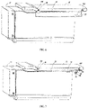
FIG. 4 is a structural schematic view of the drawer shown inFIG. 2 when in a closed state; -
FIG. 5 is a structural schematic view in which a base inFIG. 4 is hidden; -
FIG. 6 is a structural schematic view of the drawer shown inFIG. 2 when in an open state; -
FIG. 7 is a structural schematic view in which a base inFIG. 6 is hidden; -
FIG. 8 is a structural schematic view showing the cooperation of the base and a lifting assembly in the present invention; -
FIG. 9 is a structural schematic view of a gear in the present invention. - Listing of parts denoted by reference numbers: 100 storage device, 1---box body, 10---drawer, 11---drawer body, 12---cover, 121---first support shaft, 122---second support shaft, 2---lifting assembly, 21---gear, 211---first gear portion, 212---second gear portion, 22---first rack, 23---transmission member, 231--- support portion, 232---second rack, 24---limiting mechanism, 25---base, 251 guide groove, 2511---opening, 252---gear groove, 253---support groove, 26---support rod, 261---support leg, 27---fixed mechanism, 13---sealing strip.
- To make the objectives, technical solutions and advantages of the present application more apparent, technical solutions of the present application will be described clearly and thoroughly with reference to specific embodiments and corresponding figures. Based on the embodiments in the present application, all other embodiments obtained by those having ordinary skill in the art without making inventive efforts all fall within the protection scope of the present application.
- Referring to
FIG. 1 andFIG. 2 , the present invention provides astorage device 100, comprising a box body 1 with anopening 2511 on a front side and adrawer 10 received in the box body 1. Thestorage device 100 may be a refrigerator, cabinet or the like. - The
drawer 10 comprises adrawer body 11 and acover 12. For ease of description, thecover 12 is defined as being located above thedrawer body 11, a direction in which thedrawer body 11 moves to open thedrawer 10 is a forward direction, a direction in which thedrawer 10 is closed is a rearward direction, and a widthwise direction of thedrawer body 11 is a left-right direction. - The
drawer 10 further comprises asealing strip 13 fixed on a side of thecover 12 facing towards thedrawer body 11. When thecover 12 covers thedrawer body 11, thesealing strip 13 may seal a gap between thecover 12 and thedrawer body 11, thereby achieving the sealing of thedrawer 10. Thesealing strip 13 is generally made of a plastic member, an elastic silicone member etc. with a certain elasticity. - In a specific embodiment of the present invention, the
storage device 100 further comprises a lifting assembly 2 disposed between thedrawer 10 and the box body 1, and the lifting assembly 2 is disposed on at least one side of left and right sides of thecover 12 to drive thecover 12 to rise or fall. - As shown in
FIG. 3 through FIG. 9 , the lifting assembly 2 comprises agear 21 disposed fixedly relative to the box body 1, and the lifting assembly 2 further comprises afirst rack 22 disposed on thedrawer body 11 and engaging with one side of thegear 21, and atransmission member 23 cooperating with the other side of thegear 21. Thetransmission member 23 has asupport portion 231 connected with thecover 12, and asecond rack 232 extending downward from thesupport portion 231, thesecond rack 232 engaging with thegear 21. - As shown in
FIG. 4 through FIG. 7 , the lifting assembly 2 is configured in a way that when thedrawer 10 is drawn, thefirst rack 22 moves forward and drives thegear 21 to rotate, and thegear 21 drives thetransmission member 23 to move upward to lift thecover 12; when thedrawer 10 is closed, thefirst rack 22 moves backward and drives thegear 21 to rotate, and thegear 21 drives thetransmission member 23 to move downward to lower thecover 12. - Through the cooperative transmission of the
first rack 22, thegear 21 and thetransmission member 23, thecover 12 can be easily driven to rise or fall by mechanical transmission during the opening and closing process of thedrawer 10, which is labor-saving and stable and smooth throughout the process. - Specifically, the
gear 21 may be fixed on an inner wall of the box body 1 or on any fixed structure inside the box body 1 so that thegear 21 can be driven by thefirst rack 22 to rotate. As shown inFIG. 5 andFIG. 7 , thefirst rack 22 may be a section or an entirety of a front-rear length of thedrawer body 11. When thedrawer 10 is closed, a position where thefirst rack 22 engages with thegear 21 is an engagement-starting position; after thedrawer 10 is drawn open, thefirst rack 22 moves forward to disengage from thegear 21, and thegear 21 stops rotating, or thefirst rack 22 always engages with thegear 21; an effective transmission length of thefirst rack 22 and thegear 21 is a length from the engagement-starting position to an disengaging position, or an engaging length from the engagement-starting position to a position where thedrawer 10 is drawn completely open. - As shown in
FIG. 9 , thegear 21 comprises afirst gear portion 211 engaging with thefirst rack 22, and asecond gear portion 212 engaging with thesecond rack 232. A ratio of a perimeter of a tooth root circle of thefirst gear portion 211 to a perimeter of a tooth root circle of thesecond gear portion 212 is a set value. A ratio of the effective transmission length of thefirst rack 22 and thegear 21 to the length of thesecond rack 232 is not greater than the set value. In this way, it can be ensured that thesecond rack 232 always engages with thegear 21 when thegear 21 disengages from thefirst rack 22 or when thedrawer 10 is drawn completely open, so that thegear 21 drives thesecond rack 232 to achieve a continuous mechanical transmission when thedrawer body 11 is pushed backward until thefirst rack 22 engages with thegear 21. - In the present embodiment, a depth of tooth grooves of the
second gear portion 212 is smaller than the depth of tooth grooves of thefirst gear portion 211, and a depth of tooth grooves of thesecond rack 232 is smaller than the depth of tooth grooves of thefirst rack 22, thereby facilitating the engagement of thesecond gear portion 212 and thesecond rack 232. - The
second rack 232 is formed to extend obliquely downward from thesupport portion 231, so that thetransmission member 23 is inclined and in a straight line or an arc-shaped curve. In the present embodiment, thetransmission member 23 is inclined and in an arc-shaped curve, so that a degree of engagement between thesecond rack 232 and thegear 21 is increased, which facilitates thegear 21 to transmit power to thesecond rack 232, thereby making thetransmission member 23 easy to move upward. - The
first rack 22 is disposed on an upper side of thegear 21, thetransmission member 23 is inclined forward and downward from a position where thesupport portion 231 is connected with thecover 12, and thesecond rack 232 is engaged on a lower right side of thegear 21 so that thefirst rack 22 moves forward to drive thegear 21 to rotate counterclockwise, and thegear 21 drives thetransmission member 23 to move backward and upward to cause thecover 12 to move upward and backward. - In other embodiments, the
transmission member 23 may be inclined backward and downward from a position where thesupport portion 231 is connected with thecover 12, thesecond rack 232 is engaged on the lower right side of thegear 21, thefirst rack 22 moves forward to bring thegear 21 to rotate counterclockwise, and thegear 21 drives thetransmission member 23 to move forward and upward to cause thecover 12 to move upward and forward. Similarly, thefirst rack 22 may also be disposed on a lower side of thegear 21, thetransmission member 23 may be inclined backward and downward or forward and downward from the position where thesupport portion 231 is connected with thecover 12, and accordingly thesecond rack 232 is engaged on a lower left side or an upper left side of thegear 21, so that thefirst rack 22 moves forward to drive thegear 21 to rotate clockwise, and thegear 21 drives thetransmission member 23 to move forward and upward or rearward or upward to cause thecover 12 to move upward and forward or upward and backward. - As shown in
FIG. 4 through FIG. 7 , thecover 12 has afirst support shaft 121 extending outward. Thesupport portion 231 is a section of the entire length of thetransmission member 23 and is made of a hard material. A side of thesupport portion 231 away from thesecond rack 232 is snap-fitted on a circumferential side of thefirst support shaft 121. On the one hand, thesupport portion 231 may easily drive thecover 12 to rise or fall, and on the other hand, thesupport portion 231 can be mounted and detached conveniently; in other embodiments, thesupport portion 231 may also be configured to be, as a whole, fixed on thefirst support shaft 121, and can also easily drives thecover 12 to rise or fall. - In the present embodiment, a material of the
second rack 232 is a flexible material, so that the degree of engagement of thesecond rack 232 and thegear 21 is increased, which facilitates thegear 21 to transmit power to thesecond rack 232 so that thetransmission member 23 can be easily moved upward. The lifting assembly 2 further comprises a limitingmechanism 24 disposed on a side of thetransmission member 23 away from thegear 21 to prevent thesecond rack 232 from disengaging from thegear 21, and facilitates the engagement of thesecond rack 232 with thegear 21. - As shown in
FIG. 8 , the lifting assembly 2 further comprises a base 25 fixed on the box body 1. Thebase 25 is provided with aguide groove 251 for receiving thetransmission member 23. The limitingmechanism 24 constitutes at least a portion of a side wall of theguide groove 251. Theguide groove 251 has anopening 2511 at an upper end for allowing thesupport portion 231 to pass through theopening 2511 and connect with thecover 12. The base 25 further has agear groove 252 communicated with theguide groove 251 and configured to receive thegear 21, which can prevent thesecond rack 232 from disengaging from thegear 21, and facilitate the engagement of thesecond rack 232 with thegear 21. - The
cover 12 further has asecond support shaft 122 extending outward. The lifting assembly 2 further comprises asupport rod 26 and a fixedmechanism 27 disposed fixedly relative to the box body 1. An upper end of thesupport rod 26 is rotatably connected to thesecond support shaft 122, and a lower end of thesupport rod 26 is rotatably connected to the fixedmechanism 27. When thedrawer 10 is closed, thesupport rod 26 is disposed inclinedly. When thetransmission member 23 is inclined rearward and downward from the position where thesupport portion 231 is connected with thecover 12, the upper end of thesupport rod 26 is located at a arear side of the lower end; when thetransmission member 23 is inclined forward and downward from the position where thesupport portion 231 is connected with thecover 12, the upper end of thesupport rod 26 is located at a front side of the lower end. As such, when thecover 12 is driven by thetransmission member 23 to move upward and backward or move upward and forward, the upper end of thesupport rod 26 is driven so that axes of the upper and lower ends are aligned with a vertical direction, and thesupport rod 26 can play an auxiliary supporting role after thecover 12 rises and ensure the stability of the drawing process. - As shown in
FIG. 8 , thebase 25 is further provided with asupport groove 253 for receiving thesupport rod 26, the fixedmechanism 27 is disposed on an inner wall of thesupport groove 253, and an end of thesupport rod 26 connected to the fixedmechanism 27 is provided with a pair of outwardly-extending support legs which stand on a bottom wall of thesupport groove 253 when thesupport rod 26 is driven by thecover 12 to an upright state, so that thesupport rod 26 supports more stably. - The present invention further provides a refrigerator comprising the
storage device 100 as described above. Thestorage device 100 is in a sealed state when thedrawer 10 is closed, and facilitates storing food or items to be kept fresh; when thedrawer 10 is opened, the user can draw conveniently, which is labor-saving and stable and smooth throughout the process and improves the user's experience. - To sum up, in the
storage device 100 provided by the present invention, the lifting assembly 2 is configured in a way that when thedrawer 10 is drawn, thefirst rack 22 moves forward and drives thegear 21 to rotate, and thegear 21 drives thetransmission member 23 to move upward to lift thecover 12; when thedrawer 10 is closed, thefirst rack 22 moves backward and drives thegear 21 to rotate, and thegear 21 drives thetransmission member 23 to move downward to lower thecover 12. The whole process is labor-saving and stable and smooth. The refrigerator having such astorage device 100 facilitates storing food or items to be kept fresh. - What are described above are only preferred embodiments of the present invention. It should be appreciated that those skilled in the art may also make several variations and improvements without departing from the inventive concept of the present invention. All these variations and improvements fall within the protection scope of the present invention.
Claims (11)
- A storage device, comprising a box body with an opening on a front side and a drawer received in the box body, the drawer comprising a drawer body and a cover, wherein the storage device further comprises a lifting assembly disposed between the drawer and the box body, the lifting assembly comprises a gear disposed fixedly relative to the box body, a first rack disposed on the drawer body and engaging with a side of the gear, and a transmission member cooperating with the other side of the gear, the transmission member has a support portion connected with the cover, and a second rack extending downward from the support portion, the second rack engaging with the gear;
the lifting assembly is configured in a way that when the drawer is drawn, the first rack moves forward and drives the gear to rotate, and the gear drives the transmission member to move upward to lift the cover; when the drawer is closed, the first rack moves backward and drives the gear to rotate, and the gear drives the transmission member to move downward to lower the cover. - The storage device according to claim 1, wherein the second rack is formed to extend obliquely downward from the support portion, the first rack is disposed on an upper side or a lower side of the gear, the second rack engages with an upper right side or a lower right side of the gear when the first rack is disposed on the upper side of the gear, and the second rack engages with an upper left side or a lower left side of the gear when the first rack is disposed on the lower side of the gear.
- The storage device according to claim 1, wherein the gear comprises a first gear portion engaging with the first rack, and a second gear portion engaging with the second rack, a ratio of a perimeter of a tooth root circle of the first gear portion to a perimeter of a tooth root circle of the second gear portion is a set value, and a ratio of an effective transmission length of the first rack and the gear to the length of the second rack is not greater than the set value.
- The storage device according to claim 3, wherein a depth of tooth grooves of the first gear portion is smaller than the depth of tooth grooves of the second gear portion.
- The storage device according to claim 1, wherein a material of the second rack is a flexible material, the lifting assembly further comprises a limiting mechanism disposed on a side of the transmission member away from the gear to prevent the second rack from disengaging from the gear.
- The storage device according to claim 1, wherein the cover further has a second support shaft extending outward, the lifting assembly further comprises a support rod and a fixed mechanism disposed fixedly relative to the box body, an upper end of the support rod is rotatably connected to the second support shaft, and a lower end of the support rod is rotatably connected to the fixed mechanism.
- The storage device according to claim 5, wherein the lifting assembly further comprises a base fixed on the box body, the base is provided with a guide groove for receiving the transmission member, the limiting mechanism constitutes at least a portion of a side wall of the guide groove, the guide groove has an opening at an upper end for allowing the support portion to pass through the opening and connect with the cover, and the base further has a gear groove communicated with the guide groove and configured to receive the gear.
- The storage device according to claim 5, wherein the lifting assembly further comprises a base fixed on the box body, the base is provided with a support groove for receiving the support rod, the fixed mechanism is disposed on an inner wall of the support groove, and an end of the support rod connected to the fixed mechanism is provided with a pair of outwardly-extending support legs which stand on a bottom wall of the support groove when the support rod is driven by the cover to an upright state.
- The storage device according to claim 6, wherein the lifting assembly further comprises a base fixed on the box body, the base is provided with a support groove for receiving the support rod, the fixed mechanism is disposed on an inner wall of the support groove, and an end of the support rod connected to the fixed mechanism is provided with a pair of outwardly-extending support legs which stand on a bottom wall of the support groove when the support rod is driven by the cover to an upright state.
- The storage device according to claim 1, wherein the cover has a first support shaft extending outward, the support portion is a section of an entire length of the transmission member and is made of a hard material, and a side of the support portion away from the second rack is snap-fitted on a circumferential side of the first support shaft.
- A refrigerator, wherein the refrigerator comprises the storage device according to claim 1.
Applications Claiming Priority (2)
| Application Number | Priority Date | Filing Date | Title |
|---|---|---|---|
| CN201911264267.0A CN111189292B (en) | 2019-12-11 | 2019-12-11 | Storage device and refrigerator with same |
| PCT/CN2020/135156 WO2021115366A1 (en) | 2019-12-11 | 2020-12-10 | Storage device and refrigerator having same |
Publications (2)
| Publication Number | Publication Date |
|---|---|
| EP4075083A1 true EP4075083A1 (en) | 2022-10-19 |
| EP4075083A4 EP4075083A4 (en) | 2023-01-18 |
Family
ID=70705800
Family Applications (1)
| Application Number | Title | Priority Date | Filing Date |
|---|---|---|---|
| EP20899990.4A Pending EP4075083A4 (en) | 2019-12-11 | 2020-12-10 | Storage device and refrigerator having same |
Country Status (4)
| Country | Link |
|---|---|
| EP (1) | EP4075083A4 (en) |
| CN (1) | CN111189292B (en) |
| AU (1) | AU2020400764B2 (en) |
| WO (1) | WO2021115366A1 (en) |
Families Citing this family (2)
| Publication number | Priority date | Publication date | Assignee | Title |
|---|---|---|---|---|
| CN111189292B (en) * | 2019-12-11 | 2021-10-29 | 青岛海尔电冰箱有限公司 | Storage device and refrigerator with same |
| CN114017972B (en) * | 2021-12-07 | 2023-11-03 | 重庆海尔制冷电器有限公司 | Refrigerator and control method thereof |
Family Cites Families (11)
| Publication number | Priority date | Publication date | Assignee | Title |
|---|---|---|---|---|
| CN203405053U (en) * | 2013-06-18 | 2014-01-22 | 海信容声(广东)冰箱有限公司 | Drawer structure used in fruit and vegetable chamber |
| CN203946345U (en) * | 2014-06-30 | 2014-11-19 | 鑫宏益科技有限公司 | Vacuum storing vessel |
| CN104236217B (en) * | 2014-09-15 | 2016-05-18 | 合肥美的电冰箱有限公司 | Refrigerator |
| CN104848647B (en) * | 2015-05-29 | 2017-10-27 | 合肥华凌股份有限公司 | Refrigerator drawer component and refrigerator |
| US9982937B2 (en) * | 2015-08-20 | 2018-05-29 | Dometic Sweden Ab | Appliance with geared drawer assembly |
| CN106595212B (en) * | 2016-12-30 | 2018-05-29 | 青岛海尔股份有限公司 | Drawer appliance and the refrigerator with the drawer appliance |
| JP2018189318A (en) * | 2017-05-09 | 2018-11-29 | 日本電産サンキョー株式会社 | Driving device and refrigerator drawer opening device |
| EP4361543A2 (en) * | 2017-12-29 | 2024-05-01 | LG Electronics Inc. | Refrigerator |
| KR102451425B1 (en) * | 2018-02-06 | 2022-10-05 | 엘지전자 주식회사 | A Refrigerator |
| KR102510856B1 (en) * | 2018-03-26 | 2023-03-15 | 엘지전자 주식회사 | Refrigerator |
| CN111189292B (en) * | 2019-12-11 | 2021-10-29 | 青岛海尔电冰箱有限公司 | Storage device and refrigerator with same |
-
2019
- 2019-12-11 CN CN201911264267.0A patent/CN111189292B/en active Active
-
2020
- 2020-12-10 AU AU2020400764A patent/AU2020400764B2/en active Active
- 2020-12-10 EP EP20899990.4A patent/EP4075083A4/en active Pending
- 2020-12-10 WO PCT/CN2020/135156 patent/WO2021115366A1/en unknown
Also Published As
| Publication number | Publication date |
|---|---|
| CN111189292B (en) | 2021-10-29 |
| CN111189292A (en) | 2020-05-22 |
| EP4075083A4 (en) | 2023-01-18 |
| AU2020400764A1 (en) | 2022-07-07 |
| WO2021115366A1 (en) | 2021-06-17 |
| AU2020400764B2 (en) | 2023-07-27 |
Similar Documents
| Publication | Publication Date | Title |
|---|---|---|
| EP4075083A1 (en) | Storage device and refrigerator having same | |
| KR102100192B1 (en) | Refrigerator | |
| WO2017121250A1 (en) | Drawer assembly, refrigerator having the drawer assembly and control method for the refrigerator | |
| US7472974B2 (en) | Refrigerator with storage bin | |
| CN101421573B (en) | Refrigerator | |
| KR102440261B1 (en) | Refrigerator | |
| KR20130116741A (en) | A sealing structure for a vegetables container of a refrigerator | |
| USD977837S1 (en) | Drawer unit | |
| KR20050033107A (en) | Refrigerator | |
| JP2009186141A (en) | Refrigerator | |
| JP2002522738A (en) | Refrigerator door opening and closing device | |
| KR20030084072A (en) | vegetable tray of refrigerator open/close structure | |
| EP2256444A2 (en) | Refrigerator with height-adjustable receiving apparatus | |
| WO2018121784A1 (en) | Drawer assembly and refrigerator having same | |
| US8632144B2 (en) | Food storage drawer and container | |
| US4831735A (en) | Adjustment height can opener | |
| CN106546046B (en) | Refrigerator | |
| KR100785117B1 (en) | The auto-opening vessel | |
| KR200486921Y1 (en) | device for assisting drawer in opening and closing with self automatic closing function | |
| CN104949448A (en) | Drawer | |
| JP2004301356A (en) | Shelf device and refrigerator equipped therewith | |
| CN209027182U (en) | A kind of refrigerator | |
| CN216745076U (en) | Refrigeration device | |
| KR20170042191A (en) | Gear Box | |
| KR100481079B1 (en) | Refrigerator for Cabbage and Radish Pickle |
Legal Events
| Date | Code | Title | Description |
|---|---|---|---|
| STAA | Information on the status of an ep patent application or granted ep patent |
Free format text: STATUS: THE INTERNATIONAL PUBLICATION HAS BEEN MADE |
|
| PUAI | Public reference made under article 153(3) epc to a published international application that has entered the european phase |
Free format text: ORIGINAL CODE: 0009012 |
|
| STAA | Information on the status of an ep patent application or granted ep patent |
Free format text: STATUS: REQUEST FOR EXAMINATION WAS MADE |
|
| 17P | Request for examination filed |
Effective date: 20220610 |
|
| AK | Designated contracting states |
Kind code of ref document: A1 Designated state(s): AL AT BE BG CH CY CZ DE DK EE ES FI FR GB GR HR HU IE IS IT LI LT LU LV MC MK MT NL NO PL PT RO RS SE SI SK SM TR |
|
| A4 | Supplementary search report drawn up and despatched |
Effective date: 20221220 |
|
| RIC1 | Information provided on ipc code assigned before grant |
Ipc: F25D 25/02 20060101AFI20221214BHEP |
|
| DAV | Request for validation of the european patent (deleted) | ||
| DAX | Request for extension of the european patent (deleted) | ||
| GRAP | Despatch of communication of intention to grant a patent |
Free format text: ORIGINAL CODE: EPIDOSNIGR1 |
|
| STAA | Information on the status of an ep patent application or granted ep patent |
Free format text: STATUS: GRANT OF PATENT IS INTENDED |
|
| RIC1 | Information provided on ipc code assigned before grant |
Ipc: A47B 88/00 20170101ALN20231228BHEP Ipc: F25D 25/02 20060101AFI20231228BHEP |
|
| INTG | Intention to grant announced |
Effective date: 20240126 |
|
| RIC1 | Information provided on ipc code assigned before grant |
Ipc: A47B 88/00 20170101ALN20240112BHEP Ipc: F25D 25/02 20060101AFI20240112BHEP |