EP4075058A1 - Household cooking stove combustor having upper wind intake and ultra large power - Google Patents
Household cooking stove combustor having upper wind intake and ultra large power Download PDFInfo
- Publication number
- EP4075058A1 EP4075058A1 EP20934810.1A EP20934810A EP4075058A1 EP 4075058 A1 EP4075058 A1 EP 4075058A1 EP 20934810 A EP20934810 A EP 20934810A EP 4075058 A1 EP4075058 A1 EP 4075058A1
- Authority
- EP
- European Patent Office
- Prior art keywords
- air intake
- outer ring
- central
- base
- tube
- Prior art date
- Legal status (The legal status is an assumption and is not a legal conclusion. Google has not performed a legal analysis and makes no representation as to the accuracy of the status listed.)
- Granted
Links
Images



Classifications
-
- F—MECHANICAL ENGINEERING; LIGHTING; HEATING; WEAPONS; BLASTING
- F23—COMBUSTION APPARATUS; COMBUSTION PROCESSES
- F23D—BURNERS
- F23D14/00—Burners for combustion of a gas, e.g. of a gas stored under pressure as a liquid
- F23D14/02—Premix gas burners, i.e. in which gaseous fuel is mixed with combustion air upstream of the combustion zone
- F23D14/04—Premix gas burners, i.e. in which gaseous fuel is mixed with combustion air upstream of the combustion zone induction type, e.g. Bunsen burner
- F23D14/06—Premix gas burners, i.e. in which gaseous fuel is mixed with combustion air upstream of the combustion zone induction type, e.g. Bunsen burner with radial outlets at the burner head
-
- F—MECHANICAL ENGINEERING; LIGHTING; HEATING; WEAPONS; BLASTING
- F23—COMBUSTION APPARATUS; COMBUSTION PROCESSES
- F23D—BURNERS
- F23D14/00—Burners for combustion of a gas, e.g. of a gas stored under pressure as a liquid
- F23D14/02—Premix gas burners, i.e. in which gaseous fuel is mixed with combustion air upstream of the combustion zone
-
- F—MECHANICAL ENGINEERING; LIGHTING; HEATING; WEAPONS; BLASTING
- F23—COMBUSTION APPARATUS; COMBUSTION PROCESSES
- F23D—BURNERS
- F23D14/00—Burners for combustion of a gas, e.g. of a gas stored under pressure as a liquid
- F23D14/02—Premix gas burners, i.e. in which gaseous fuel is mixed with combustion air upstream of the combustion zone
- F23D14/04—Premix gas burners, i.e. in which gaseous fuel is mixed with combustion air upstream of the combustion zone induction type, e.g. Bunsen burner
- F23D14/06—Premix gas burners, i.e. in which gaseous fuel is mixed with combustion air upstream of the combustion zone induction type, e.g. Bunsen burner with radial outlets at the burner head
- F23D14/065—Premix gas burners, i.e. in which gaseous fuel is mixed with combustion air upstream of the combustion zone induction type, e.g. Bunsen burner with radial outlets at the burner head with injector axis inclined to the burner head axis
-
- F—MECHANICAL ENGINEERING; LIGHTING; HEATING; WEAPONS; BLASTING
- F23—COMBUSTION APPARATUS; COMBUSTION PROCESSES
- F23D—BURNERS
- F23D14/00—Burners for combustion of a gas, e.g. of a gas stored under pressure as a liquid
- F23D14/26—Burners for combustion of a gas, e.g. of a gas stored under pressure as a liquid with provision for a retention flame
-
- F—MECHANICAL ENGINEERING; LIGHTING; HEATING; WEAPONS; BLASTING
- F23—COMBUSTION APPARATUS; COMBUSTION PROCESSES
- F23D—BURNERS
- F23D14/00—Burners for combustion of a gas, e.g. of a gas stored under pressure as a liquid
- F23D14/46—Details
-
- F—MECHANICAL ENGINEERING; LIGHTING; HEATING; WEAPONS; BLASTING
- F23—COMBUSTION APPARATUS; COMBUSTION PROCESSES
- F23D—BURNERS
- F23D14/00—Burners for combustion of a gas, e.g. of a gas stored under pressure as a liquid
- F23D14/46—Details
- F23D14/48—Nozzles
-
- F—MECHANICAL ENGINEERING; LIGHTING; HEATING; WEAPONS; BLASTING
- F23—COMBUSTION APPARATUS; COMBUSTION PROCESSES
- F23D—BURNERS
- F23D14/00—Burners for combustion of a gas, e.g. of a gas stored under pressure as a liquid
- F23D14/46—Details
- F23D14/62—Mixing devices; Mixing tubes
- F23D14/64—Mixing devices; Mixing tubes with injectors
-
- F—MECHANICAL ENGINEERING; LIGHTING; HEATING; WEAPONS; BLASTING
- F23—COMBUSTION APPARATUS; COMBUSTION PROCESSES
- F23D—BURNERS
- F23D14/00—Burners for combustion of a gas, e.g. of a gas stored under pressure as a liquid
- F23D14/46—Details
- F23D14/70—Baffles or like flow-disturbing devices
-
- F—MECHANICAL ENGINEERING; LIGHTING; HEATING; WEAPONS; BLASTING
- F23—COMBUSTION APPARATUS; COMBUSTION PROCESSES
- F23C—METHODS OR APPARATUS FOR COMBUSTION USING FLUID FUEL OR SOLID FUEL SUSPENDED IN A CARRIER GAS OR AIR
- F23C2900/00—Special features of, or arrangements for combustion apparatus using fluid fuels or solid fuels suspended in air; Combustion processes therefor
- F23C2900/06041—Staged supply of oxidant
-
- F—MECHANICAL ENGINEERING; LIGHTING; HEATING; WEAPONS; BLASTING
- F23—COMBUSTION APPARATUS; COMBUSTION PROCESSES
- F23D—BURNERS
- F23D2900/00—Special features of, or arrangements for burners using fluid fuels or solid fuels suspended in a carrier gas
- F23D2900/14—Special features of gas burners
- F23D2900/14062—Special features of gas burners for cooking ranges having multiple flame rings
-
- F—MECHANICAL ENGINEERING; LIGHTING; HEATING; WEAPONS; BLASTING
- F23—COMBUSTION APPARATUS; COMBUSTION PROCESSES
- F23D—BURNERS
- F23D2900/00—Special features of, or arrangements for burners using fluid fuels or solid fuels suspended in a carrier gas
- F23D2900/14—Special features of gas burners
- F23D2900/14063—Special features of gas burners for cooking ranges having one flame ring fed by multiple venturis
Definitions
- the present disclosure relates to a household stove burner, in particular to a household stove burner with upper intake air and super-high power.
- a household stove burner with upper intake air and super-high power includes a cup body, a distributor base, a central distributor, an outer ring distributor, an ignition needle and an induction needle.
- the cup body includes a base plate, a central distributor base penetrating through the base plate, a central fire air intake tube communicating with a lower end of the central distributor base, an outer ring pre-mixing cavity arranged on a lower surface at the rear of the base plate and passing through the base plate, a left outer ring air intake tube, a right outer ring air intake tube, a primary air intake cavity arranged at the front of the base plate, an ignition needle fixing hole and an induction needle fixing hole.
- the distributor base includes an outer ring fuel gas tank, and the distributor base is communicated with the outer ring pre-mixing cavity.
- the purpose of the present disclosure is to provide a household stove burner with upper intake air and super-high power, which is has the characteristics of high power and small load reduction gradient.
- a household stove burner with upper intake air and super-high power includes a cup body, a distributor base, a central distributor, an outer ring distributor, an ignition needle and an induction needle.
- the cup body includes a base plate, a central distributor base penetrating through the base plate, a central fire air intake tube communicating with a lower end of the central distributor base, an outer ring pre-mixing cavity arranged on a lower surface at the rear of the base plate and passing through the base plate, a left outer ring air intake tube, a right outer ring air intake tube, a primary air intake cavity arranged at the front of the base plate, an ignition needle fixing hole and an induction needle fixing hole.
- the distributor base includes an outer ring fuel gas tank, and the distributor base is communicated with the outer ring pre-mixing cavity.
- the household stove burner is characterized in that the outer ring pre-mixing cavity is a small semicircle, a slow flow and steady flow plate along an axial direction is arranged on a circular wall in the outer ring pre-mixing cavity, and the slow flow and steady flow plate is along a diameter line in forward and backward directions.
- the central fire air intake tube includes a central inner screw cavity and a central light tube portion that are arranged in an air intake end, and a diameter of the central inner screw cavity is greater than that of the central light tube portion.
- the left outer ring air intake tube includes a left inner screw cavity and a left light tube portion that are arranged in the air intake end, and a diameter of the left inner screw portion is greater than that of the left light tube portion.
- the right outer ring air intake tube includes a right inner screw cavity and a right light tube portion that are arranged in the air intake end, and a diameter of the right inner screw portion is greater than that of the right light tube portion.
- the primary air intake cavity includes a central air intake portion, a left air intake portion and a right air intake portion, the air intake end of the central fire air intake tube is provided with the pre-mixing cavity, which is communicated with the central air intake portion.
- the left air intake portion is communicated with a left space at the front of the air intake end of the left outer ring air intake tube
- the right air intake portion is communicated with a right space at the front of the air intake end of the right outer ring air intake tube.
- a lower opened air intake cavity is formed in a base plate of the outer ring fuel gas tank of the distributor base, the air intake cavity is respectively provided a left diversion trench and a right diversion trench in anticlockwise and clockwise directions, and a top plate of the air intake cavity is provided with a radial plate.
- the household stove burner further includes an air intake base, a central air intake tube, a left air intake tube and a right air intake tube.
- the air intake base includes a central air intake interface, a central air outlet base in the central air intake interface, a transverse outer ring air intake tube, a left air outlet base, a right air outlet base and an outer ring air intake interface, and nozzles are respectively arranged on the central air outlet base, the left air outlet base and the right air outlet base.
- An air intake end of the central air intake tube is arranged at the central outer screw base, an air intake end of the left air intake tube is arranged at the left outer screw base, and the right outer screw base is arranged on the right air intake tube.
- the outer ring distributor includes an inner ring wall plate, a top inverted cone cover plate, an outer ring wall plate, an outer interface arranged at a lower end of the outer ring wall plate and a flame stabilizing plate surrounding the upper end of the outer ring wall plate.
- An outer ring combustion hole, an outer ring flame stabilizing slot and an air guide hole for communicating the outer ring flame stabilizing slot and the outer ring distributor inner cavity are formed in the outer ring wall plate.
- the outer ring flame stabilizing slot is located at the lower part of the outer ring combustion hole, an acute angle is between an axial line of the outer ring combustion hole and a radial outer level, and an acute angle is between the outer ring flame stabilizing slot and the radial outer level.
- the central outer screw base of the central air intake tube is screwed with the central inner screw cavity of the central fire air intake tube, and a gap is between the central air intake tube and the light tube portion of the central fire air intake tube.
- the left outer screw base of the left air intake tube is screwed with the left inner screw cavity of the left outer ring air intake tube, and a gap is between the left air intake tube and the light tube portion of the left outer ring air intake tube.
- the right outer screw base of the right air intake tube is screwed with the right inner screw cavity of the right outer ring air intake tube, and a gap is between the right air intake tube and the light tube portion of the right outer ring air intake tube.
- the air intake base is fixedly connected to a front end of the base plate of the cup body, and nozzles on the central air outlet base, the left air outlet base and the right air outlet base are respectively opposite to the central air intake tube, the left air intake tube and the right air intake tube.
- a lower end of the air intake cavity of the distributor base is docked with the outer ring pre-mixing cavity, the outer interface of the outer ring distributor is inserted into the outer ring fuel gas tank, and the inner ring wall plate of the outer ring fuel gas tank is inserted into the outer ring distributor.
- the household stove burner with upper intake air and super-high power is characterized in that: a screw hole is formed in the slow flow and steady flow plate, a connecting hole is formed in the top plate of the air intake cavity, the connecting hole penetrates through the radial plate, the slow flow and steady flow plate is docked with the radial plate, and a screw passes through the connecting hole and is screwed with the screw hole.
- the household stove burner with upper intake air and super-high power is characterized in that: the two ends of the primary air intake cavity are provided with support column bases, in which screw holes are formed.
- a connecting base is arranged on the base plate of the outer ring fuel gas tank of the distributor base, and the screw passes through the connecting hole on the connecting base and is screwed with the screw holes on the support column bases.
- the household stove burner with upper intake air and super-high power is characterized in that: the volume of the air intake cavity is less than that of the outer ring pre-mixing cavity.
- the household stove burner with upper intake air and super-high power is characterized in that: a central air intake hole is formed in the central light tube portion of the central fire air intake tube, a left air intake hole is formed in the left light tube portion of the left outer ring air intake tube, and a right air intake hole is formed in the right light tube portion of the right outer right air intake tube.
- the household stove burner with upper intake air and super-high power is characterized in that: air outlet holes penetrating through the top plate are respectively formed in the two ends of the top plate of the lower opened air intake cavity of the distributor base.
- the present disclosure is a household stove burner with upper intake air and super-high power.
- the outer ring flame stabilizing slot and the flame stabilizing plate are arranged on the outer ring distributor to prevent the generation of the outer ring firm flame.
- the central air intake tube and the light tube portion of the central fire air intake tube are arranged at intervals, the left air intake tube and the light tube portion of the left outer ring air intake tube are arranged at intervals, and the right air intake tube and the light tube portion of the right outer ring air intake tube are arranged at intervals, so that the heat dissipation performance is improved.
- a household stove burner with upper intake air and super-high power includes a cup body 1, a distributor base 2, a central distributor 3, an outer ring distributor 4, an ignition needle 5 and an induction needle 6.
- the cup body 1 includes a base plate 11, a central distributor base 12 penetrating through the base plate, a central fire air intake tube 13 communicating with a lower end of the central distributor base, an outer ring pre-mixing cavity 14 arranged on a lower surface at the rear of the base plate and passing through the base plate, a left outer ring air intake tube 15, a right outer ring air intake tube 16, a primary air intake cavity 17 arranged at the front of the base plate, an ignition needle fixing hole and an induction needle fixing hole.
- the distributor base 2 includes an outer ring fuel gas tank 2A, and the outer ring fuel gas tank 2A of the distributor base 2 is communicated with the outer ring pre-mixing cavity 14.
- the outer ring pre-mixing cavity 14 is a small semicircle, a slow flow and steady flow plate 141 along an axial direction is arranged on a circular wall in the outer ring pre-mixing cavity 14, and the slow flow and steady flow plate 141 is along a diameter line in the forward and backward directions.
- the small semicircular central angle is less than 180 degrees, and the chord length is less than the diameter of the round.
- the central fire air intake tube 13 includes a central inner screw cavity 131 and a central light tube portion 132 that are arranged in an air intake end, and a diameter of the central inner screw cavity 131 is greater than that of the central light tube portion 132.
- the left outer ring air intake tube 15 includes a left inner screw cavity 151 and a left light tube portion 152 that are arranged in the air intake end, and a diameter of the left inner screw portion 151 is greater than that of the left light tube portion 152.
- the right outer ring air intake tube 16 includes a right inner screw cavity 161 and a right light tube portion 162 that are arranged in the air intake end, and a diameter of the right inner screw portion 161 is greater than that of the right light tube portion 162.
- the primary air intake cavity 17 includes a central air intake portion 171, a left air intake portion 172 and a right air intake portion 173, the air intake end of the central fire air intake tube 13 is provided with the pre-mixing cavity 133, which is communicated with the central air intake portion 171.
- the left air intake portion 172 is communicated with a left space at the front of the air intake end of the left outer ring air intake tube 15, and the right air intake portion 173 is communicated with a right space at the front of the air intake end of the right outer ring air intake tube 16.
- the lower opened air intake cavity 2B is formed in the base plate of the outer ring fuel gas tank 2A of the distributor base 2, the air intake cavity 2B is respectively provided the left diversion trench 2C1 and the right diversion trench 2C2 in anticlockwise and clockwise directions, and the top plate of the air intake cavity 2B is provided with the radial plate 2D.
- the air outlet holes 2B1 penetrating through the top plate are respectively formed in the two ends of the top plate of the lower opened air intake cavity 2B of the distributor base 2.
- the household stove burner further includes an air intake base 7, a central air intake tube 8, a left air intake tube 9 and a right air intake tube 10.
- the air intake base 7 includes a central air intake interface 71, a central air outlet base 72 in the central air intake interface, a transverse outer ring air intake tube 73, a left air outlet base 741, a right air outlet base 742 and an outer ring air intake interface 75.
- the outer ring air intake interface is communicated with the transverse outer ring air intake tube 73, the two ends of the transverse outer ring air intake tube 73 are communicated with the left air outlet base 741 and the right air outlet base 742, and nozzles are respectively arranged on the central air outlet base 72, the left air outlet base 741 and the right air outlet base 742.
- the air intake end of the central air intake tube 8 is provided with a central outer screw base 81
- the air intake end of the left air intake tube 9 is provided with a left outer screw base 91
- a right outer screw base 101 is arranged on the right air intake tube 10.
- the outer ring distributor 4 includes an inner ring wall plate 41, a top inverted cone cover plate 42, an outer ring wall plate 43, an outer interface 44 arranged at the lower end of the outer ring wall plate and a flame stabilizing plate 45 surrounding the upper end of the outer ring wall plate.
- An outer ring combustion hole 431, an outer ring flame stabilizing slot 432 and an air guide hole 433 for communicating the outer ring flame stabilizing slot 432 and the outer ring distributor inner cavity are formed in the outer ring wall plate 43.
- the outer ring flame stabilizing slot 432 is located at the lower part of the outer ring combustion hole 431, an acute angle ⁇ is between an axial line of the outer ring combustion hole 431 and a radial outer level, and an acute angle ⁇ is between the outer ring flame stabilizing slot and the radial outer level.
- the flame stabilizing plate 45 is prepared by extending the top inverted cone cover plate 42 in the radial outer side, the outer ring flame stabilizing slot 432 burns the lower part of the flame of the outer ring combustion hole 431 to prevent the flame, and the flame stabilizing plate 45 also plays the role of preventing the flame.
- the central outer screw base 81 of the central air intake tube 8 is screwed with the central inner screw cavity 131 of the central fire air intake tube 13, and the central gap is between the central air intake tube 8 and the light tube portion 132 of the central fire air intake tube 13.
- the setting of the central gap may reduce the temperature of the central air intake tube 8.
- the left outer screw base 91 of the left air intake tube 9 is screwed with the left inner screw cavity 151 of the left outer ring air intake tube 15, and the right gap is between the left air intake tube 9 and the light tube portion 152 of the left outer ring air intake tube 15.
- the setting of the left gap reduces the temperature of the left air intake tube 9.
- the right outer screw base 101 of the right air intake tube 10 is screwed with the right inner screw cavity 161 of the right outer ring air intake tube 16, and the left gap is between the right air intake tube 10 and the light tube portion 162 of the right outer ring air intake tube 16.
- the setting of the left gap reduces the temperature of the right air intake tube 10.
- the air intake base 7 is fixedly connected to the front end of the base plate 11 of the cup body 1, and the nozzles on the central air outlet base 72, the left air outlet base 741 and the right air outlet base 742 are respectively opposite to the central air intake tube, the left air intake tube and the right air intake tube.
- the lower end of the air intake cavity 2B of the distributor base 2 is docked with the outer ring pre-mixing cavity 14, the outer interface 44 of the outer ring distributor 4 is inserted into the outer ring fuel gas tank 3A, and the inner ring wall plate of the outer ring fuel gas tank 3A is inserted into the outer ring distributor 4.
- a screw hole is formed in the slow flow and steady flow plate 141
- a connecting hole is formed in the top plate of the air intake cavity 2B
- the connecting hole penetrates through the radial plate 2D
- the slow flow and steady flow plate 141 is docked with the radial plate 2D
- a screw passes through the connecting hole and is screwed with the screw hole.
- the two ends of the primary air intake cavity 17 are provided with support column bases 174, in which screw holes are formed.
- a connecting base 2E is arranged on the base plate of the outer ring fuel gas tank 2A of the distributor base 2, and the screw passes through the connecting hole on the connecting base 2E and is screwed with the screw holes on the support column bases 174.
- the volume of the air intake cavity 2B is less than that of the outer ring pre-mixing cavity 14.
- the mixed gas of the fuel gas and the air is compressed and quickly enters the left diversion trench 2C1 and the right diversion trench 2C2 from the air intake cavity 2B.
- a central air intake hole 1321 along the radial direction is formed in the central light tube portion 132 of the central fire air intake tube 13, the central air intake hole 1321 is communicated with the central gap, and the central air intake hole 1321 plays the effects of entering primary air and heat dissipation.
- a left air intake hole 1521 is formed in the left light tube portion 152 of the left outer ring air intake tube 15, the left air intake hole 1521 is communicated with the left gap to play the effects of entering primary air and heat dissipation.
- a right air intake hole 1621 is formed in the right light tube portion 162 of the right outer ring air intake tube 16, and the right air intake hole 1621 is communicated with the right gap to play the effects of entering primary air and heat dissipation.
- the high power is 3.8-4.0kw, and super-high power is above 5.0kw.
- the technical solution of the present disclosure may realize 5.2kw, a test is carried out by the national standard testing method.
- the combustion of the present disclosure is 15min, and the load is 5.16kw.
- the maximum power is 4kw
- the combustion is 15min
- the load is 3.91kw.
- the test is carried out every 15min.
- the load is reduced by 3.88%; compared with the load when burning for 15min, when the present disclosure burns for 45min, the load is reduced by 5.43%, and compared with the load when burning for 15min, when the present disclosure burns for 60min, the load is reduced by 5.81%.
- the load is reduced by 4.86%.
- the load is reduced by 6.14%, and compared with the load when burning for 15min, when the upper air intake burner burns for 60min, the load is reduced by 6.39%.
Landscapes
- Engineering & Computer Science (AREA)
- Chemical & Material Sciences (AREA)
- Combustion & Propulsion (AREA)
- Mechanical Engineering (AREA)
- General Engineering & Computer Science (AREA)
- Gas Burners (AREA)
Abstract
Description
- The present disclosure relates to a household stove burner, in particular to a household stove burner with upper intake air and super-high power.
- In the prior art, a household stove burner with upper intake air and super-high power includes a cup body, a distributor base, a central distributor, an outer ring distributor, an ignition needle and an induction needle. The cup body includes a base plate, a central distributor base penetrating through the base plate, a central fire air intake tube communicating with a lower end of the central distributor base, an outer ring pre-mixing cavity arranged on a lower surface at the rear of the base plate and passing through the base plate, a left outer ring air intake tube, a right outer ring air intake tube, a primary air intake cavity arranged at the front of the base plate, an ignition needle fixing hole and an induction needle fixing hole. The distributor base includes an outer ring fuel gas tank, and the distributor base is communicated with the outer ring pre-mixing cavity. Existing problems: poor heat dissipation performance, resulting in load increased along working time and great load reduction gradient.
- The purpose of the present disclosure is to provide a household stove burner with upper intake air and super-high power, which is has the characteristics of high power and small load reduction gradient.
- The present disclosure is achieved as follows: a household stove burner with upper intake air and super-high power includes a cup body, a distributor base, a central distributor, an outer ring distributor, an ignition needle and an induction needle. The cup body includes a base plate, a central distributor base penetrating through the base plate, a central fire air intake tube communicating with a lower end of the central distributor base, an outer ring pre-mixing cavity arranged on a lower surface at the rear of the base plate and passing through the base plate, a left outer ring air intake tube, a right outer ring air intake tube, a primary air intake cavity arranged at the front of the base plate, an ignition needle fixing hole and an induction needle fixing hole. The distributor base includes an outer ring fuel gas tank, and the distributor base is communicated with the outer ring pre-mixing cavity. The household stove burner is characterized in that the outer ring pre-mixing cavity is a small semicircle, a slow flow and steady flow plate along an axial direction is arranged on a circular wall in the outer ring pre-mixing cavity, and the slow flow and steady flow plate is along a diameter line in forward and backward directions.
- The central fire air intake tube includes a central inner screw cavity and a central light tube portion that are arranged in an air intake end, and a diameter of the central inner screw cavity is greater than that of the central light tube portion. The left outer ring air intake tube includes a left inner screw cavity and a left light tube portion that are arranged in the air intake end, and a diameter of the left inner screw portion is greater than that of the left light tube portion. The right outer ring air intake tube includes a right inner screw cavity and a right light tube portion that are arranged in the air intake end, and a diameter of the right inner screw portion is greater than that of the right light tube portion.
- The primary air intake cavity includes a central air intake portion, a left air intake portion and a right air intake portion, the air intake end of the central fire air intake tube is provided with the pre-mixing cavity, which is communicated with the central air intake portion. The left air intake portion is communicated with a left space at the front of the air intake end of the left outer ring air intake tube, and the right air intake portion is communicated with a right space at the front of the air intake end of the right outer ring air intake tube.
- A lower opened air intake cavity is formed in a base plate of the outer ring fuel gas tank of the distributor base, the air intake cavity is respectively provided a left diversion trench and a right diversion trench in anticlockwise and clockwise directions, and a top plate of the air intake cavity is provided with a radial plate.
- The household stove burner further includes an air intake base, a central air intake tube, a left air intake tube and a right air intake tube.
- The air intake base includes a central air intake interface, a central air outlet base in the central air intake interface, a transverse outer ring air intake tube, a left air outlet base, a right air outlet base and an outer ring air intake interface, and nozzles are respectively arranged on the central air outlet base, the left air outlet base and the right air outlet base.
- An air intake end of the central air intake tube is arranged at the central outer screw base, an air intake end of the left air intake tube is arranged at the left outer screw base, and the right outer screw base is arranged on the right air intake tube.
- The outer ring distributor includes an inner ring wall plate, a top inverted cone cover plate, an outer ring wall plate, an outer interface arranged at a lower end of the outer ring wall plate and a flame stabilizing plate surrounding the upper end of the outer ring wall plate. An outer ring combustion hole, an outer ring flame stabilizing slot and an air guide hole for communicating the outer ring flame stabilizing slot and the outer ring distributor inner cavity are formed in the outer ring wall plate. The outer ring flame stabilizing slot is located at the lower part of the outer ring combustion hole, an acute angle is between an axial line of the outer ring combustion hole and a radial outer level, and an acute angle is between the outer ring flame stabilizing slot and the radial outer level.
- The central outer screw base of the central air intake tube is screwed with the central inner screw cavity of the central fire air intake tube, and a gap is between the central air intake tube and the light tube portion of the central fire air intake tube. The left outer screw base of the left air intake tube is screwed with the left inner screw cavity of the left outer ring air intake tube, and a gap is between the left air intake tube and the light tube portion of the left outer ring air intake tube. The right outer screw base of the right air intake tube is screwed with the right inner screw cavity of the right outer ring air intake tube, and a gap is between the right air intake tube and the light tube portion of the right outer ring air intake tube. The air intake base is fixedly connected to a front end of the base plate of the cup body, and nozzles on the central air outlet base, the left air outlet base and the right air outlet base are respectively opposite to the central air intake tube, the left air intake tube and the right air intake tube. A lower end of the air intake cavity of the distributor base is docked with the outer ring pre-mixing cavity, the outer interface of the outer ring distributor is inserted into the outer ring fuel gas tank, and the inner ring wall plate of the outer ring fuel gas tank is inserted into the outer ring distributor.
- The household stove burner with upper intake air and super-high power is characterized in that: a screw hole is formed in the slow flow and steady flow plate, a connecting hole is formed in the top plate of the air intake cavity, the connecting hole penetrates through the radial plate, the slow flow and steady flow plate is docked with the radial plate, and a screw passes through the connecting hole and is screwed with the screw hole.
- The household stove burner with upper intake air and super-high power is characterized in that: the two ends of the primary air intake cavity are provided with support column bases, in which screw holes are formed.
- A connecting base is arranged on the base plate of the outer ring fuel gas tank of the distributor base, and the screw passes through the connecting hole on the connecting base and is screwed with the screw holes on the support column bases.
- The household stove burner with upper intake air and super-high power is characterized in that: the volume of the air intake cavity is less than that of the outer ring pre-mixing cavity.
- The household stove burner with upper intake air and super-high power is characterized in that: a central air intake hole is formed in the central light tube portion of the central fire air intake tube, a left air intake hole is formed in the left light tube portion of the left outer ring air intake tube, and a right air intake hole is formed in the right light tube portion of the right outer right air intake tube.
- The household stove burner with upper intake air and super-high power is characterized in that: air outlet holes penetrating through the top plate are respectively formed in the two ends of the top plate of the lower opened air intake cavity of the distributor base.
- The present disclosure is a household stove burner with upper intake air and super-high power. The outer ring flame stabilizing slot and the flame stabilizing plate are arranged on the outer ring distributor to prevent the generation of the outer ring firm flame. The central air intake tube and the light tube portion of the central fire air intake tube are arranged at intervals, the left air intake tube and the light tube portion of the left outer ring air intake tube are arranged at intervals, and the right air intake tube and the light tube portion of the right outer ring air intake tube are arranged at intervals, so that the heat dissipation performance is improved.
-
-
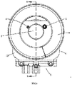
FIG. 1 is a front view of the present disclosure. -
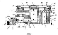
FIG. 2 is an A-A view ofFIG. 1 . -
FIG. 3 is a B-B view ofFIG. 2 . -
FIG. 4 is a C-C view ofFIG. 3 . -
FIG. 5 is a first solid exploded view of the present disclosure. -
FIG. 6 is a second solid exploded view of the present disclosure. -
FIG. 7 is a third solid exploded view of the present disclosure. -
FIG. 8 is a fourth solid exploded view of the present disclosure. -
FIG. 9 is a first section view of an outer ring distributor of the present disclosure. -
FIG. 10 is a second section view of an outer ring distributor of the present disclosure. -
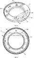
FIG. 11 is a first solid diagram of a distributor base of the present disclosure. -
FIG. 12 is a second solid diagram of a distributor base of the present disclosure. -
FIG. 13 is a front view of a distributor base of the present disclosure. -
FIG. 14 is a thermal load variation diagram of the present disclosure and the prior art. -
FIG. 15 is a thermal load reduction rate comparison diagram of the present disclosure and the prior art. - The present disclosure is further described in combination with drawings below.
- As shown in
FIG. 1 andFIG .2 , a household stove burner with upper intake air and super-high power includes acup body 1, adistributor base 2, acentral distributor 3, anouter ring distributor 4, anignition needle 5 and aninduction needle 6. Thecup body 1 includes abase plate 11, acentral distributor base 12 penetrating through the base plate, a central fireair intake tube 13 communicating with a lower end of the central distributor base, an outer ring pre-mixingcavity 14 arranged on a lower surface at the rear of the base plate and passing through the base plate, a left outer ringair intake tube 15, a right outer ringair intake tube 16, a primaryair intake cavity 17 arranged at the front of the base plate, an ignition needle fixing hole and an induction needle fixing hole. Thedistributor base 2 includes an outer ringfuel gas tank 2A, and the outer ringfuel gas tank 2A of thedistributor base 2 is communicated with the outer ring pre-mixingcavity 14. - The outer ring pre-mixing
cavity 14 is a small semicircle, a slow flow andsteady flow plate 141 along an axial direction is arranged on a circular wall in the outer ring pre-mixingcavity 14, and the slow flow andsteady flow plate 141 is along a diameter line in the forward and backward directions. The small semicircular central angle is less than 180 degrees, and the chord length is less than the diameter of the round. - The central fire
air intake tube 13 includes a centralinner screw cavity 131 and a centrallight tube portion 132 that are arranged in an air intake end, and a diameter of the centralinner screw cavity 131 is greater than that of the centrallight tube portion 132. The left outer ringair intake tube 15 includes a left inner screw cavity 151 and a leftlight tube portion 152 that are arranged in the air intake end, and a diameter of the left inner screw portion 151 is greater than that of the leftlight tube portion 152. The right outer ringair intake tube 16 includes a rightinner screw cavity 161 and a rightlight tube portion 162 that are arranged in the air intake end, and a diameter of the rightinner screw portion 161 is greater than that of the rightlight tube portion 162. - The primary
air intake cavity 17 includes a centralair intake portion 171, a leftair intake portion 172 and a rightair intake portion 173, the air intake end of the central fireair intake tube 13 is provided with thepre-mixing cavity 133, which is communicated with the centralair intake portion 171. The leftair intake portion 172 is communicated with a left space at the front of the air intake end of the left outer ringair intake tube 15, and the rightair intake portion 173 is communicated with a right space at the front of the air intake end of the right outer ringair intake tube 16. - The lower opened
air intake cavity 2B is formed in the base plate of the outer ringfuel gas tank 2A of thedistributor base 2, theair intake cavity 2B is respectively provided the left diversion trench 2C1 and the right diversion trench 2C2 in anticlockwise and clockwise directions, and the top plate of theair intake cavity 2B is provided with theradial plate 2D. The air outlet holes 2B1 penetrating through the top plate are respectively formed in the two ends of the top plate of the lower openedair intake cavity 2B of thedistributor base 2. - The household stove burner further includes an
air intake base 7, a centralair intake tube 8, a left air intake tube 9 and a rightair intake tube 10. - The
air intake base 7 includes a centralair intake interface 71, a centralair outlet base 72 in the central air intake interface, a transverse outer ringair intake tube 73, a leftair outlet base 741, a rightair outlet base 742 and an outer ring air intake interface 75. The outer ring air intake interface is communicated with the transverse outer ringair intake tube 73, the two ends of the transverse outer ringair intake tube 73 are communicated with the leftair outlet base 741 and the rightair outlet base 742, and nozzles are respectively arranged on the centralair outlet base 72, the leftair outlet base 741 and the rightair outlet base 742. - The air intake end of the central
air intake tube 8 is provided with a centralouter screw base 81, the air intake end of the left air intake tube 9 is provided with a leftouter screw base 91, and a rightouter screw base 101 is arranged on the rightair intake tube 10. - As shown in
FIG. 9 and FIG. 10 , theouter ring distributor 4 includes an innerring wall plate 41, a top invertedcone cover plate 42, an outerring wall plate 43, anouter interface 44 arranged at the lower end of the outer ring wall plate and aflame stabilizing plate 45 surrounding the upper end of the outer ring wall plate. An outerring combustion hole 431, an outer ringflame stabilizing slot 432 and anair guide hole 433 for communicating the outer ringflame stabilizing slot 432 and the outer ring distributor inner cavity are formed in the outerring wall plate 43. The outer ringflame stabilizing slot 432 is located at the lower part of the outerring combustion hole 431, an acute angle α is between an axial line of the outerring combustion hole 431 and a radial outer level, and an acute angle β is between the outer ring flame stabilizing slot and the radial outer level. Theflame stabilizing plate 45 is prepared by extending the top invertedcone cover plate 42 in the radial outer side, the outer ringflame stabilizing slot 432 burns the lower part of the flame of the outerring combustion hole 431 to prevent the flame, and theflame stabilizing plate 45 also plays the role of preventing the flame. - The central
outer screw base 81 of the centralair intake tube 8 is screwed with the centralinner screw cavity 131 of the central fireair intake tube 13, and the central gap is between the centralair intake tube 8 and thelight tube portion 132 of the central fireair intake tube 13. The setting of the central gap may reduce the temperature of the centralair intake tube 8. The leftouter screw base 91 of the left air intake tube 9 is screwed with the left inner screw cavity 151 of the left outer ringair intake tube 15, and the right gap is between the left air intake tube 9 and thelight tube portion 152 of the left outer ringair intake tube 15. The setting of the left gap reduces the temperature of the left air intake tube 9. The rightouter screw base 101 of the rightair intake tube 10 is screwed with the rightinner screw cavity 161 of the right outer ringair intake tube 16, and the left gap is between the rightair intake tube 10 and thelight tube portion 162 of the right outer ringair intake tube 16. The setting of the left gap reduces the temperature of the rightair intake tube 10. Theair intake base 7 is fixedly connected to the front end of thebase plate 11 of thecup body 1, and the nozzles on the centralair outlet base 72, the leftair outlet base 741 and the rightair outlet base 742 are respectively opposite to the central air intake tube, the left air intake tube and the right air intake tube. The lower end of theair intake cavity 2B of thedistributor base 2 is docked with the outerring pre-mixing cavity 14, theouter interface 44 of theouter ring distributor 4 is inserted into the outer ring fuel gas tank 3A, and the inner ring wall plate of the outer ring fuel gas tank 3A is inserted into theouter ring distributor 4. - As a further improvement of the present disclosure: a screw hole is formed in the slow flow and
steady flow plate 141, a connecting hole is formed in the top plate of theair intake cavity 2B, the connecting hole penetrates through theradial plate 2D, the slow flow andsteady flow plate 141 is docked with theradial plate 2D, and a screw passes through the connecting hole and is screwed with the screw hole. - The two ends of the primary
air intake cavity 17 are provided withsupport column bases 174, in which screw holes are formed. - A connecting
base 2E is arranged on the base plate of the outer ringfuel gas tank 2A of thedistributor base 2, and the screw passes through the connecting hole on the connectingbase 2E and is screwed with the screw holes on the support column bases 174. - The volume of the
air intake cavity 2B is less than that of the outerring pre-mixing cavity 14. When entering theair intake cavity 2B from the outerring pre-mixing cavity 14, the mixed gas of the fuel gas and the air is compressed and quickly enters the left diversion trench 2C1 and the right diversion trench 2C2 from theair intake cavity 2B. - As a further improvement of the present disclosure: a central
air intake hole 1321 along the radial direction is formed in the centrallight tube portion 132 of the central fireair intake tube 13, the centralair intake hole 1321 is communicated with the central gap, and the centralair intake hole 1321 plays the effects of entering primary air and heat dissipation. A leftair intake hole 1521 is formed in the leftlight tube portion 152 of the left outer ringair intake tube 15, the leftair intake hole 1521 is communicated with the left gap to play the effects of entering primary air and heat dissipation. A rightair intake hole 1621 is formed in the rightlight tube portion 162 of the right outer ringair intake tube 16, and the rightair intake hole 1621 is communicated with the right gap to play the effects of entering primary air and heat dissipation. - In the technical field of the household stove burner, the high power is 3.8-4.0kw, and super-high power is above 5.0kw.
- When the technical solution of the present disclosure is above 5.0kw, the load reduction gradient is small, so that the super-high power can be realized.
- As shown in
FIG. 14 , the technical solution of the present disclosure may realize 5.2kw, a test is carried out by the national standard testing method. According to the national standard testing method, the combustion of the present disclosure is 15min, and the load is 5.16kw. - For the current product sold in the market, the maximum power is 4kw, the combustion is 15min, and the load is 3.91kw.
- As shown in
FIG. 15 , based on the national standard and the actual measured load after burning for 15min, the test is carried out every 15min. - Compared with the load when burning for 15min, when the present disclosure burns for 30min, the load is reduced by 3.88%; compared with the load when burning for 15min, when the present disclosure burns for 45min, the load is reduced by 5.43%, and compared with the load when burning for 15min, when the present disclosure burns for 60min, the load is reduced by 5.81%.
- Compared with the load when burning for 15min, when the upper air intake burner sold in the market burns for 30min, the load is reduced by 4.86%. Compared with the load when burning for 15min, when the upper air intake burner burns for 45min, the load is reduced by 6.14%, and compared with the load when burning for 15min, when the upper air intake burner burns for 60min, the load is reduced by 6.39%.
- It can be known, from the above analysis and comparison, the thermal load reduction of the present disclosure is small, and the upper air intake burner sold in the market has great thermal load reduction.
- The above is only the preferred implementation mode of the present disclosure. It is to be pointed out that those of ordinary skill in the art may further make a plurality of transformations and improvements without departing from the concept of the present disclosure and all of these fall within the scope of protection of the present disclosure.
Claims (6)
- A household stove burner with upper intake air and super-high power, comprising a cup body, a distributor base, a central distributor, an outer ring distributor, an ignition needle and an induction needle; the cup body comprises a base plate, a central distributor base penetrating through the base plate, a central fire air intake tube communicating with a lower end of the central distributor base, an outer ring pre-mixing cavity arranged on a lower surface at the rear of the base plate and passing through the base plate, a left outer ring air intake tube, a right outer ring air intake tube, a primary air intake cavity arranged at the front of the base plate, an ignition needle fixing hole and an induction needle fixing hole; the distributor base comprises an outer ring fuel gas tank, and the distributor base is communicated with the outer ring pre-mixing cavity, wherein the outer ring pre-mixing cavity is a small semicircle, a slow flow and steady flow plate along an axial direction is arranged on a circular wall in the outer ring pre-mixing cavity, and the slow flow and steady flow plate is along a diameter line in forward and backward directions;wherein the central fire air intake tube comprises a central inner screw cavity and a central light tube portion that are arranged in an air intake end, and a diameter of the central inner screw cavity is greater than that of the central light tube portion; the left outer ring air intake tube comprises a left inner screw cavity and a left light tube portion that are arranged in the air intake end, and a diameter of the left inner screw portion is greater than that of the left light tube portion; and the right outer ring air intake tube comprises a right inner screw cavity and a right light tube portion that are arranged in the air intake end, and a diameter of the right inner screw portion is greater than that of the right light tube portion;wherein the primary air intake cavity comprises a central air intake portion, a left air intake portion and a right air intake portion, the air intake end of the central fire air intake tube is provided with the pre-mixing cavity, which is communicated with the central air intake portion; the left air intake portion is communicated with a left space at the front of the air intake end of the left outer ring air intake tube, and the right air intake portion is communicated with a right space at the front of the air intake end of the right outer ring air intake tube;wherein a lower opened air intake cavity is formed in a base plate of the outer ring fuel gas tank of the distributor base, the air intake cavity is respectively provided a left diversion trench and a right diversion trench in anticlockwise and clockwise directions, and a top plate of the air intake cavity is provided with a radial plate;further comprising an air intake base, a central air intake tube, a left air intake tube and a right air intake tube, the air intake base comprises a central air intake interface, a central air outlet base in the central air intake interface, a transverse outer ring air intake tube, a left air outlet base, a right air outlet base and an outer ring air intake interface, and nozzles are respectively arranged on the central air outlet base, the left air outlet base and the right air outlet base; an air intake end of the central air intake tube is arranged at the central outer screw base, an air intake end of the left air intake tube is arranged at the left outer screw base, and a right outer screw base is arranged on the right air intake tube; the outer ring distributor comprises an inner ring wall plate, a top inverted cone cover plate, an outer ring wall plate, an outer interface arranged at a lower end of the outer ring wall plate and a flame stabilizing plate surrounding the upper end of the outer ring wall plate; an outer ring combustion hole, an outer ring flame stabilizing slot and an air guide hole for communicating the outer ring flame stabilizing slot and the outer ring distributor inner cavity are formed in the outer ring wall plate; the outer ring flame stabilizing slot is located at the lower part of the outer ring combustion hole, an acute angle is between an axial line of the outer ring combustion hole and a radial outer level, and an acute angle is between the outer ring flame stabilizing slot and the radial outer level;wherein the central outer screw base of the central air intake tube is screwed with the central inner screw cavity of the central fire air intake tube, and a gap is between the central air intake tube and the light tube portion of the central fire air intake tube; the left outer screw base of the left air intake tube is screwed with the left inner screw cavity of the left outer ring air intake tube, and a gap is between the left air intake tube and the light tube portion of the left outer ring air intake tube; the right outer screw base of the right air intake tube is screwed with the right inner screw cavity of the right outer ring air intake tube, and a gap is between the right air intake tube and the light tube portion of the right outer ring air intake tube; the air intake base is fixedly connected to a front end of the base plate of the cup body, and nozzles on the central air outlet base, the left air outlet base and the right air outlet base are respectively opposite to the central air intake tube, the left air intake tube and the right air intake tube; a lower end of the air intake cavity of the distributor base is docked with the outer ring pre-mixing cavity, the outer interface of the outer ring distributor is inserted into the outer ring fuel gas tank, and the inner ring wall plate of the outer ring fuel gas tank is inserted into the outer ring distributor; a central air intake hole is formed in the central light tube portion of the central fire air intake tube, a left air intake hole is formed in the left light tube portion of the left outer ring air intake tube, and a right air intake hole is formed in the right light tube portion of the right outer ring air intake tube.
- The household stove burner with upper intake air and super-high power according to claim 1, wherein a screw hole is formed in the slow flow and steady flow plate, a connecting hole is formed in the top plate of the air intake cavity, the connecting hole penetrates through the radial plate, the slow flow and steady flow plate is docked with the radial plate, and a screw passes through the connecting hole and is screwed with the screw hole.
- The household stove burner with upper intake air and super-high power according to claim 1, wherein the two ends of the primary air intake cavity are provided with support column bases, in which screw holes are formed;
wherein a connecting base is arranged on the base plate of the outer ring fuel gas tank of the distributor base, and a screw passes through the connecting hole on the connecting base and is screwed with the screw holes on the support column bases. - The household stove burner with upper intake air and super-high power according to claim 1, wherein the volume of the air intake cavity is less than that of the outer ring pre-mixing cavity.
- The top-fed ultra-high-power household stove burner according to claim 1, wherein a central air inlet hole is formed in a central tube part of a central flame intake pipe; a left air inlet hole is formed in a left tube part of the left outer-ring intake pipe; and a right air inlet hole is formed in a right tube part of the right outer-ring intake pipe.
- The household stove burner with upper intake air and super-high power according to claims 1, 2, 3 or 4, wherein air outlet holes penetrating through the top plate are respectively formed in the two ends of the top plate of the lower opened air intake cavity of the distributor base.
Applications Claiming Priority (2)
| Application Number | Priority Date | Filing Date | Title |
|---|---|---|---|
| CN202010372288.0A CN111664449B (en) | 2020-05-06 | 2020-05-06 | A kind of upper air intake super power household stove burner |
| PCT/CN2020/108178 WO2021223341A1 (en) | 2020-05-06 | 2020-08-10 | Household cooking stove combustor having upper wind intake and ultra large power |
Publications (4)
| Publication Number | Publication Date |
|---|---|
| EP4075058A1 true EP4075058A1 (en) | 2022-10-19 |
| EP4075058A4 EP4075058A4 (en) | 2024-01-03 |
| EP4075058B1 EP4075058B1 (en) | 2025-10-08 |
| EP4075058C0 EP4075058C0 (en) | 2025-10-08 |
Family
ID=72383247
Family Applications (1)
| Application Number | Title | Priority Date | Filing Date |
|---|---|---|---|
| EP20934810.1A Active EP4075058B1 (en) | 2020-05-06 | 2020-08-10 | Household cooking stove burner |
Country Status (4)
| Country | Link |
|---|---|
| US (1) | US11976814B2 (en) |
| EP (1) | EP4075058B1 (en) |
| CN (1) | CN111664449B (en) |
| WO (1) | WO2021223341A1 (en) |
Families Citing this family (3)
| Publication number | Priority date | Publication date | Assignee | Title |
|---|---|---|---|---|
| CN112161268A (en) * | 2020-11-04 | 2021-01-01 | 宁波神力燃具有限公司 | Furnace end, combustor and gas-cooker |
| CN112594743B (en) * | 2020-12-12 | 2025-01-28 | 广东合胜厨电科技有限公司 | A modular stove burner with upper air intake |
| CN222230536U (en) * | 2024-04-11 | 2024-12-24 | 广东合胜厨电科技有限公司 | Upper air inlet stove burner |
Family Cites Families (18)
| Publication number | Priority date | Publication date | Assignee | Title |
|---|---|---|---|---|
| GB2322696B (en) * | 1997-02-28 | 1999-01-06 | Tri Square Ind Co Ltd | Gas burner |
| IT1311777B1 (en) * | 1999-01-29 | 2002-03-19 | Ohg Defendi Srl | GAS BURNER, PARTICULARLY FOR BUILT-IN HOB. |
| US6322354B1 (en) | 2000-07-17 | 2001-11-27 | Wolf Appliance Company, Llc | Stacked dual gas burner |
| US6875008B1 (en) * | 2003-01-29 | 2005-04-05 | Callidus Technologies, L.L.C. | Lean pre-mix low NOx burner |
| KR100681345B1 (en) * | 2005-02-03 | 2007-02-15 | 최진민 | Burner for Upstream Gas Boiler |
| EP2198199A4 (en) * | 2007-10-10 | 2011-12-14 | Garland Commercial Ind Llc | Venturi housing assembly and method |
| CN104713087B (en) * | 2015-03-12 | 2017-10-27 | 广东美的厨房电器制造有限公司 | Bottom cup lid and burner and gas appliance |
| WO2017051364A2 (en) * | 2015-09-24 | 2017-03-30 | Defendi Italy S.R.L. | A gas burner with multiple rings of flames for cooking hobs |
| CN107667256B (en) * | 2015-05-19 | 2019-10-18 | Somipress注射金属协会股份责任有限公司 | Twin Flame Crown Gas Burners |
| CN108266728B (en) * | 2017-01-03 | 2020-06-12 | 广东星立方厨电集团有限公司 | A cooker burner with an inner ring and an outer ring in opposite directions of air intake |
| CN107036099A (en) * | 2017-06-01 | 2017-08-11 | 华帝股份有限公司 | Three-ring distributor and three-ring combustor using same |
| CN108105768B (en) * | 2018-01-11 | 2024-05-28 | 曾祥林 | Burner of kitchen range with hidden injection pipe |
| CN108954306B (en) * | 2018-08-24 | 2024-05-17 | 浙江帅丰电器股份有限公司 | Burner |
| CN210267207U (en) * | 2019-07-01 | 2020-04-07 | 吴红英 | Stove burner assembly |
| IT201900010935A1 (en) * | 2019-07-04 | 2021-01-04 | Ego Elektro Geraetebau Gmbh | Multi-crown gas burner. |
| CN110848680A (en) * | 2019-10-11 | 2020-02-28 | 广东绿壳新能源有限公司 | Semi-premixed natural gas pipe type combustor |
| CN110608436A (en) * | 2019-11-06 | 2019-12-24 | 杭州老板电器股份有限公司 | Burners and Gas Hobs |
| US20230220992A1 (en) * | 2022-01-10 | 2023-07-13 | JK Burnersystems LLC | High Output Gas Burner, Such As For A Food Cooking Apparatus |
-
2020
- 2020-05-06 CN CN202010372288.0A patent/CN111664449B/en active Active
- 2020-08-10 WO PCT/CN2020/108178 patent/WO2021223341A1/en not_active Ceased
- 2020-08-10 US US17/793,038 patent/US11976814B2/en active Active
- 2020-08-10 EP EP20934810.1A patent/EP4075058B1/en active Active
Also Published As
| Publication number | Publication date |
|---|---|
| EP4075058B1 (en) | 2025-10-08 |
| US20240044485A1 (en) | 2024-02-08 |
| EP4075058C0 (en) | 2025-10-08 |
| US11976814B2 (en) | 2024-05-07 |
| EP4075058A4 (en) | 2024-01-03 |
| CN111664449B (en) | 2021-08-03 |
| WO2021223341A1 (en) | 2021-11-11 |
| CN111664449A (en) | 2020-09-15 |
Similar Documents
| Publication | Publication Date | Title |
|---|---|---|
| EP4075058A1 (en) | Household cooking stove combustor having upper wind intake and ultra large power | |
| CN208139268U (en) | Gas fired-boiler burner and gas-fired Boiler System | |
| CN104566374A (en) | Adjustable upper intake air combustor | |
| CN109185883B (en) | Inner ring fire cover, burner and gas stove | |
| CN104421941A (en) | Fuel gas nozzle for gas stove and gas stove with fuel gas nozzle | |
| CN102052677A (en) | Industrial gas burner | |
| CN201180990Y (en) | Premixed high-efficiency energy-saving environment friendly combustor with ignition and flame-out protection device | |
| CN111795385A (en) | Burner with flame enhancement | |
| CN103047648A (en) | Differential Power Gas Cooktop Burners | |
| CN109237475A (en) | A kind of vertical more injection tubular type tricyclic ignition combustors | |
| CN208431761U (en) | A kind of adjustable upward-air-feeding type stove combustor | |
| CN107327845B (en) | Burner structure of gas stove and gas stove | |
| CN115013811A (en) | Ultra-low nitrogen combustion head for horizontally-mounted vertical combustion burner | |
| CN2476728Y (en) | Stove with infrared combustion apparatus and atmospheric flame combustion apparatus | |
| CN203478254U (en) | Gas nozzle for gas stoves and gas stove with same | |
| CN203703970U (en) | Infrared heating device | |
| CN206439822U (en) | Turbine adds exocoel energy-saving burner | |
| JP3581981B2 (en) | Cassette cooker | |
| CN221349211U (en) | Gas ignition gun | |
| CN219439982U (en) | Through type container | |
| CN223470198U (en) | Combustor with compact structure | |
| CN113847599B (en) | Combustor with double-channel central gas channel structure | |
| CN220061773U (en) | Tail gas burner of phosphorus furnace | |
| CN221222755U (en) | Nozzle unit of gas burning torch | |
| CN221258891U (en) | Burner body of gas burning torch |
Legal Events
| Date | Code | Title | Description |
|---|---|---|---|
| STAA | Information on the status of an ep patent application or granted ep patent |
Free format text: STATUS: THE INTERNATIONAL PUBLICATION HAS BEEN MADE |
|
| PUAI | Public reference made under article 153(3) epc to a published international application that has entered the european phase |
Free format text: ORIGINAL CODE: 0009012 |
|
| STAA | Information on the status of an ep patent application or granted ep patent |
Free format text: STATUS: REQUEST FOR EXAMINATION WAS MADE |
|
| 17P | Request for examination filed |
Effective date: 20220715 |
|
| AK | Designated contracting states |
Kind code of ref document: A1 Designated state(s): AL AT BE BG CH CY CZ DE DK EE ES FI FR GB GR HR HU IE IS IT LI LT LU LV MC MK MT NL NO PL PT RO RS SE SI SK SM TR |
|
| DAV | Request for validation of the european patent (deleted) | ||
| DAX | Request for extension of the european patent (deleted) | ||
| A4 | Supplementary search report drawn up and despatched |
Effective date: 20231130 |
|
| RIC1 | Information provided on ipc code assigned before grant |
Ipc: F23D 14/70 20060101ALI20231124BHEP Ipc: F23D 14/64 20060101ALI20231124BHEP Ipc: F23D 14/46 20060101ALI20231124BHEP Ipc: F23D 14/48 20060101ALI20231124BHEP Ipc: F23D 14/02 20060101AFI20231124BHEP |
|
| GRAP | Despatch of communication of intention to grant a patent |
Free format text: ORIGINAL CODE: EPIDOSNIGR1 |
|
| STAA | Information on the status of an ep patent application or granted ep patent |
Free format text: STATUS: GRANT OF PATENT IS INTENDED |
|
| INTG | Intention to grant announced |
Effective date: 20250325 |
|
| GRAS | Grant fee paid |
Free format text: ORIGINAL CODE: EPIDOSNIGR3 |
|
| GRAA | (expected) grant |
Free format text: ORIGINAL CODE: 0009210 |
|
| STAA | Information on the status of an ep patent application or granted ep patent |
Free format text: STATUS: THE PATENT HAS BEEN GRANTED |
|
| AK | Designated contracting states |
Kind code of ref document: B1 Designated state(s): AL AT BE BG CH CY CZ DE DK EE ES FI FR GB GR HR HU IE IS IT LI LT LU LV MC MK MT NL NO PL PT RO RS SE SI SK SM TR |
|
| REG | Reference to a national code |
Ref country code: GB Ref legal event code: FG4D Ref country code: CH Ref legal event code: F10 Free format text: ST27 STATUS EVENT CODE: U-0-0-F10-F00 (AS PROVIDED BY THE NATIONAL OFFICE) Effective date: 20251008 |
|
| REG | Reference to a national code |
Ref country code: DE Ref legal event code: R096 Ref document number: 602020060329 Country of ref document: DE |
|
| REG | Reference to a national code |
Ref country code: IE Ref legal event code: FG4D |
|
| U01 | Request for unitary effect filed |
Effective date: 20251107 |
|
| U07 | Unitary effect registered |
Designated state(s): AT BE BG DE DK EE FI FR IT LT LU LV MT NL PT RO SE SI Effective date: 20251112 |
|
| PG25 | Lapsed in a contracting state [announced via postgrant information from national office to epo] |
Ref country code: ES Free format text: LAPSE BECAUSE OF FAILURE TO SUBMIT A TRANSLATION OF THE DESCRIPTION OR TO PAY THE FEE WITHIN THE PRESCRIBED TIME-LIMIT Effective date: 20251008 |
|
| PG25 | Lapsed in a contracting state [announced via postgrant information from national office to epo] |
Ref country code: NO Free format text: LAPSE BECAUSE OF FAILURE TO SUBMIT A TRANSLATION OF THE DESCRIPTION OR TO PAY THE FEE WITHIN THE PRESCRIBED TIME-LIMIT Effective date: 20260108 |
|
| PG25 | Lapsed in a contracting state [announced via postgrant information from national office to epo] |
Ref country code: HR Free format text: LAPSE BECAUSE OF FAILURE TO SUBMIT A TRANSLATION OF THE DESCRIPTION OR TO PAY THE FEE WITHIN THE PRESCRIBED TIME-LIMIT Effective date: 20251008 |
|
| PG25 | Lapsed in a contracting state [announced via postgrant information from national office to epo] |
Ref country code: RS Free format text: LAPSE BECAUSE OF FAILURE TO SUBMIT A TRANSLATION OF THE DESCRIPTION OR TO PAY THE FEE WITHIN THE PRESCRIBED TIME-LIMIT Effective date: 20260108 |
|
| PG25 | Lapsed in a contracting state [announced via postgrant information from national office to epo] |
Ref country code: IS Free format text: LAPSE BECAUSE OF FAILURE TO SUBMIT A TRANSLATION OF THE DESCRIPTION OR TO PAY THE FEE WITHIN THE PRESCRIBED TIME-LIMIT Effective date: 20260208 |
|
| PG25 | Lapsed in a contracting state [announced via postgrant information from national office to epo] |
Ref country code: PL Free format text: LAPSE BECAUSE OF FAILURE TO SUBMIT A TRANSLATION OF THE DESCRIPTION OR TO PAY THE FEE WITHIN THE PRESCRIBED TIME-LIMIT Effective date: 20251008 |