EP4075025A2 - Axle assembly - Google Patents
Axle assembly Download PDFInfo
- Publication number
- EP4075025A2 EP4075025A2 EP22167730.5A EP22167730A EP4075025A2 EP 4075025 A2 EP4075025 A2 EP 4075025A2 EP 22167730 A EP22167730 A EP 22167730A EP 4075025 A2 EP4075025 A2 EP 4075025A2
- Authority
- EP
- European Patent Office
- Prior art keywords
- lubricant
- central portion
- axle assembly
- conduit
- arm portion
- Prior art date
- Legal status (The legal status is an assumption and is not a legal conclusion. Google has not performed a legal analysis and makes no representation as to the accuracy of the status listed.)
- Granted
Links
Images



Classifications
-
- F—MECHANICAL ENGINEERING; LIGHTING; HEATING; WEAPONS; BLASTING
- F16—ENGINEERING ELEMENTS AND UNITS; GENERAL MEASURES FOR PRODUCING AND MAINTAINING EFFECTIVE FUNCTIONING OF MACHINES OR INSTALLATIONS; THERMAL INSULATION IN GENERAL
- F16H—GEARING
- F16H57/00—General details of gearing
- F16H57/04—Features relating to lubrication or cooling or heating
- F16H57/048—Type of gearings to be lubricated, cooled or heated
- F16H57/0482—Gearings with gears having orbital motion
- F16H57/0483—Axle or inter-axle differentials
-
- F—MECHANICAL ENGINEERING; LIGHTING; HEATING; WEAPONS; BLASTING
- F16—ENGINEERING ELEMENTS AND UNITS; GENERAL MEASURES FOR PRODUCING AND MAINTAINING EFFECTIVE FUNCTIONING OF MACHINES OR INSTALLATIONS; THERMAL INSULATION IN GENERAL
- F16H—GEARING
- F16H57/00—General details of gearing
- F16H57/04—Features relating to lubrication or cooling or heating
- F16H57/0457—Splash lubrication
-
- B—PERFORMING OPERATIONS; TRANSPORTING
- B60—VEHICLES IN GENERAL
- B60B—VEHICLE WHEELS; CASTORS; AXLES FOR WHEELS OR CASTORS; INCREASING WHEEL ADHESION
- B60B35/00—Axle units; Parts thereof ; Arrangements for lubrication of axles
- B60B35/12—Torque-transmitting axles
- B60B35/16—Axle housings
-
- F—MECHANICAL ENGINEERING; LIGHTING; HEATING; WEAPONS; BLASTING
- F16—ENGINEERING ELEMENTS AND UNITS; GENERAL MEASURES FOR PRODUCING AND MAINTAINING EFFECTIVE FUNCTIONING OF MACHINES OR INSTALLATIONS; THERMAL INSULATION IN GENERAL
- F16H—GEARING
- F16H57/00—General details of gearing
- F16H57/04—Features relating to lubrication or cooling or heating
-
- F—MECHANICAL ENGINEERING; LIGHTING; HEATING; WEAPONS; BLASTING
- F16—ENGINEERING ELEMENTS AND UNITS; GENERAL MEASURES FOR PRODUCING AND MAINTAINING EFFECTIVE FUNCTIONING OF MACHINES OR INSTALLATIONS; THERMAL INSULATION IN GENERAL
- F16H—GEARING
- F16H57/00—General details of gearing
- F16H57/04—Features relating to lubrication or cooling or heating
- F16H57/0412—Cooling or heating; Control of temperature
- F16H57/0415—Air cooling or ventilation; Heat exchangers; Thermal insulations
- F16H57/0416—Air cooling or ventilation
-
- F—MECHANICAL ENGINEERING; LIGHTING; HEATING; WEAPONS; BLASTING
- F16—ENGINEERING ELEMENTS AND UNITS; GENERAL MEASURES FOR PRODUCING AND MAINTAINING EFFECTIVE FUNCTIONING OF MACHINES OR INSTALLATIONS; THERMAL INSULATION IN GENERAL
- F16H—GEARING
- F16H57/00—General details of gearing
- F16H57/04—Features relating to lubrication or cooling or heating
- F16H57/042—Guidance of lubricant
-
- F—MECHANICAL ENGINEERING; LIGHTING; HEATING; WEAPONS; BLASTING
- F16—ENGINEERING ELEMENTS AND UNITS; GENERAL MEASURES FOR PRODUCING AND MAINTAINING EFFECTIVE FUNCTIONING OF MACHINES OR INSTALLATIONS; THERMAL INSULATION IN GENERAL
- F16H—GEARING
- F16H57/00—General details of gearing
- F16H57/04—Features relating to lubrication or cooling or heating
- F16H57/042—Guidance of lubricant
- F16H57/0421—Guidance of lubricant on or within the casing, e.g. shields or baffles for collecting lubricant, tubes, pipes, grooves, channels or the like
-
- F—MECHANICAL ENGINEERING; LIGHTING; HEATING; WEAPONS; BLASTING
- F16—ENGINEERING ELEMENTS AND UNITS; GENERAL MEASURES FOR PRODUCING AND MAINTAINING EFFECTIVE FUNCTIONING OF MACHINES OR INSTALLATIONS; THERMAL INSULATION IN GENERAL
- F16H—GEARING
- F16H57/00—General details of gearing
- F16H57/04—Features relating to lubrication or cooling or heating
- F16H57/042—Guidance of lubricant
- F16H57/0421—Guidance of lubricant on or within the casing, e.g. shields or baffles for collecting lubricant, tubes, pipes, grooves, channels or the like
- F16H57/0423—Lubricant guiding means mounted or supported on the casing, e.g. shields or baffles for collecting lubricant, tubes or pipes
-
- B—PERFORMING OPERATIONS; TRANSPORTING
- B60—VEHICLES IN GENERAL
- B60B—VEHICLE WHEELS; CASTORS; AXLES FOR WHEELS OR CASTORS; INCREASING WHEEL ADHESION
- B60B2900/00—Purpose of invention
- B60B2900/50—Improvement of
- B60B2900/561—Lubrication
-
- F—MECHANICAL ENGINEERING; LIGHTING; HEATING; WEAPONS; BLASTING
- F16—ENGINEERING ELEMENTS AND UNITS; GENERAL MEASURES FOR PRODUCING AND MAINTAINING EFFECTIVE FUNCTIONING OF MACHINES OR INSTALLATIONS; THERMAL INSULATION IN GENERAL
- F16D—COUPLINGS FOR TRANSMITTING ROTATION; CLUTCHES; BRAKES
- F16D65/00—Parts or details
- F16D65/02—Braking members; Mounting thereof
- F16D2065/13—Parts or details of discs or drums
- F16D2065/1304—Structure
- F16D2065/1328—Structure internal cavities, e.g. cooling channels
-
- F—MECHANICAL ENGINEERING; LIGHTING; HEATING; WEAPONS; BLASTING
- F16—ENGINEERING ELEMENTS AND UNITS; GENERAL MEASURES FOR PRODUCING AND MAINTAINING EFFECTIVE FUNCTIONING OF MACHINES OR INSTALLATIONS; THERMAL INSULATION IN GENERAL
- F16D—COUPLINGS FOR TRANSMITTING ROTATION; CLUTCHES; BRAKES
- F16D65/00—Parts or details
- F16D65/02—Braking members; Mounting thereof
- F16D65/12—Discs; Drums for disc brakes
- F16D65/128—Discs; Drums for disc brakes characterised by means for cooling
-
- F—MECHANICAL ENGINEERING; LIGHTING; HEATING; WEAPONS; BLASTING
- F16—ENGINEERING ELEMENTS AND UNITS; GENERAL MEASURES FOR PRODUCING AND MAINTAINING EFFECTIVE FUNCTIONING OF MACHINES OR INSTALLATIONS; THERMAL INSULATION IN GENERAL
- F16H—GEARING
- F16H57/00—General details of gearing
- F16H57/02—Gearboxes; Mounting gearing therein
- F16H2057/02039—Gearboxes for particular applications
- F16H2057/02043—Gearboxes for particular applications for vehicle transmissions
- F16H2057/02052—Axle units; Transfer casings for four wheel drive
-
- F—MECHANICAL ENGINEERING; LIGHTING; HEATING; WEAPONS; BLASTING
- F16—ENGINEERING ELEMENTS AND UNITS; GENERAL MEASURES FOR PRODUCING AND MAINTAINING EFFECTIVE FUNCTIONING OF MACHINES OR INSTALLATIONS; THERMAL INSULATION IN GENERAL
- F16H—GEARING
- F16H57/00—General details of gearing
- F16H57/02—Gearboxes; Mounting gearing therein
- F16H2057/02039—Gearboxes for particular applications
- F16H2057/02043—Gearboxes for particular applications for vehicle transmissions
- F16H2057/02056—Gearboxes for particular applications for vehicle transmissions for utility vehicles, e.g. tractors or agricultural machines
Definitions
- the present disclosure relates to an axle assembly for a working machine and a working machine comprising said axle assembly.
- Vehicles in particular working machines, can include an axle assembly containing a wet brake and/or gear systems (e.g. differential gearing systems) that run in a bath of lubricant e.g. oil. Braking energy and parasitic losses from the gear systems can be converted into heat, which is conducted into the oil. In some cases, air flow across the axle assembly casings cools the casings, and subsequently cools the oil to acceptable levels.
- a wet brake and/or gear systems e.g. differential gearing systems
- gear systems e.g. differential gearing systems
- lubricant e.g. oil
- Braking energy and parasitic losses from the gear systems can be converted into heat, which is conducted into the oil.
- air flow across the axle assembly casings cools the casings, and subsequently cools the oil to acceptable levels.
- thermostatic valves and heat exchangers to achieve oil cooling, for example from US 6997284 .
- this arrangement is costly and complex. In the off-highway environment, damage to a heat exchanger would be highly likely. Furthermore, a heat-exchanger would likely become clogged with mud/sand/aggregate etc. and therefore would cease to function effectively.
- the use of a thermostatic valve introduces another potential point of failure in this system.
- the present disclosure seeks to overcome or at least mitigate the problems of the prior art.
- an axle assembly for a working machine having an axle housing comprising:
- lubricant from the lubricant reservoir is propelled by the gear within an internal volume of the central portion.
- the lubricant catcher intercepts the trajectory of the propelled lubricant such that the lubricant enters the inlet of the catcher, travels along the flow path and is directed to the arm portion via the conduit assembly.
- the arm portion runs cooler than the central portion, due to better exposure to air flow and also the absence of loss inducing rotating parts, this has the effect of cooling the lubricant.
- the surface area of the axle housing can be used more effectively to improve temperature uniformity across the axle assembly, leading to lower operating lubricant temperatures in the central portion, which improves lubricant life. No heat-exchanger, valves or similar components are required, which results in an axle assembly which is simple and is more suitable for off-highway conditions.
- the gear e.g. a crown gear
- a traditional pump is not required. Rather the action of the rotating gear is sufficient to move lubricant out of the central portion. In this way, a simple way of cycling lubricant round the axle assembly is provided.
- the catcher is placed directly into the splash of lubricant from the gear and so the amount of lubricant entering the catcher is maximised.
- Axle assemblies disclosed herein are particularly useful in high speed axles that have lubricant immersed wet brakes located in close proximity to a central differential gearing system.
- the central portion may be located approximately in the centre of the axle assembly. In some embodiments, the central portion may be at any location along the axle assembly, e.g. not at the centre but offset to one side or another. In some embodiments, the central portion can be thought of as a gear housing portion.
- conduit assembly defines a flow path extending from the inlet of the lubricant catcher in a direction transverse to the axis of rotation of the gear.
- conduit assembly defines a flow path extending from the inlet of the lubricant catcher to an exterior of the axle housing, in a direction transverse to the axis of rotation of the gear.
- the gear is configured to move lubricant out of said lubricant reservoir, and the inlet of the lubricant catcher is positioned in alignment with a trajectory of movement of said lubricant, such that lubricant can enter the inlet.
- the inlet is open in a direction opposite to a direction of rotation of the gear.
- the inlet faces the direction of rotation of the gear, e.g. the inlet is positioned in line with the trajectory of the lubricant. This maximises the amount of lubricant directed out of the central portion by the lubricant catcher.
- the lubricant catcher is configured such that it can only be fitted in a single orientation with respect the central portion of the axle housing.
- the lubricant catcher can only be fitted in one position/orientation with respect to the axle housing. This ensures that the inlet and/or flow path of the lubricant catcher are optimally aligned with the trajectory of the lubricant in the central portion, thereby optimising flow out of the central portion.
- the single orientation of the lubricant catcher can be achieved by the use of offset fixing bolts or other suitable means.
- the lubricant catcher is configured such that it can be fitted in a plurality of predetermined orientations with respect to the central portion of the axle housing. In some embodiments, the lubricant catcher is configured such that it can be fitted to the central portion in any orientation.
- the lubricant catcher is located at a rear side of the central portion with respect to an intended direction of motion of the axle assembly when fitted to a machine.
- axle assembly may better fit the configuration of a working machine.
- the lubricant catcher is located at any point along a perimeter (e.g. a circumference) of the central portion of the axle housing.
- the conduit assembly comprises a bore diameter of at least 5mm, for example, at least 7mm, for example at least 10mm, for example at least 14mm, e.g. 14mm.
- the conduit assembly comprises at least one conduit external to the axle housing, said conduit being configured to direct lubricant from the central portion to the arm portion.
- the lubricant catcher extends through a wall of the central portion of the axle housing and is coupled to said conduit.
- the lubricant is quickly directed to an exterior of the axle housing, which maximises cooling.
- the lubricant catcher and conduit are integrally formed, or wherein the lubricant catcher and conduit are separate components.
- the catcher and conduit are separate components, the catcher can be more easily fitted, replaced and/or maintained, without requiring dismantling of the axle assembly.
- the lubricant catcher and/or conduit has a bore diameter of at least 10mm, e.g. at least 14mm.
- the lubricant catcher and/or conduit has a substantially constant bore diameter.
- the lubricant catcher and/or conduit comprises a non-constant bore diameter.
- the arm portion is a first arm portion and the conduit is a first conduit
- the axle assembly further comprises a second arm portion and the conduit assembly comprises a second conduit, wherein the second conduit is configured to direct lubricant from the central portion to the second arm portion.
- the or each conduit is made of a conductive material e.g. steel.
- the or each conduit is made of any suitable material, e.g. a non-conductive material.
- the lubricant catcher is made of a conductive material e.g. steel. In other embodiments, any suitable material may be used e.g. a non-conductive material.
- central portion and the or each arm portion define a shared lubricant reservoir, such that lubricant directed to the or each arm portion by the conduit assembly can return to the central portion under gravity.
- This provides a simple system for cycling lubricant from the central portion, out to the or each arm portion, and back to the central portion, without the need for any valves, pumps, or other complex parts that increase complexity, cost and also increase the number of components that could fail.
- axle assembly further comprises a wet brake system comprising one or more plates, wherein each of the one or more plates comprises an aperture configured to permit flow of lubricant therethrough.
- the axle assembly does not include any brakes.
- external disc brakes are provided external to the axle housing.
- conduit assembly is configured to direct lubricant from the central portion to a distal end of the or each arm portion.
- central portion and the or each arm portion are integrally formed. In some embodiments the central portion and the or each arm portion are separate components.
- an axle assembly for a working machine having an axle housing comprising:
- the central portion and the arm portion define a shared lubricant reservoir, such that lubricant directed to the arm portion by the conduit assembly returns to the central portion under gravity.
- axle assembly further comprises a wet brake system comprising one or more plates, wherein each of the one or more plates comprises an aperture configured to permit flow of lubricant therethrough.
- the axle assembly does not include any brakes.
- external disc brakes are provided external to the axle housing.
- axle assembly does not comprise a pump and/or valve for directing the flow of lubricant.
- central portion and the or each arm portion are integrally formed. In some embodiments the central portion and the or each arm portion are separate components.
- a working machine comprising an axle assembly as disclosed herein.
- an embodiment of this disclosure includes a machine 1 which may be a working machine.
- the working machine is a backhoe loader.
- the working machine may be a telescopic handler, a skid steer loader, a wheel loader, or a telescopic wheel loader, for example.
- Such machines may be denoted as off-highway working machines.
- the machine 1 includes a machine body 2 which may include, for example, an operator cab 3 from which an operator can operate the machine 1.
- the machine 1 has a ground engaging propulsion structure comprising a first axle assembly and a second axle assembly, each axle assembly being coupled to a pair of wheels (two wheels 4, 5 are shown in Figure 1 with one wheel 4 connected to the first axle assembly and one wheel 5 connected to the second axle assembly).
- the first axle assembly may be a front axle assembly and the second axle assembly may be a rear axle assembly.
- Either or both of the first and second axle assemblies may be an axle assembly of the type illustrated in Figure 2 .
- FIG 2 shows an axle assembly 6 having an axle housing 8 including a central portion, a first arm portion 12a and a second arm portion 12b.
- Each of the first and second arm portions 12a,b extend from the central portion 10 and house an driveshaft 7 (as shown in Figure 5 ).
- the central portion houses a gear 14 e.g. a crown gear.
- the gear 14 is configured to rotate about an axis A in a direction indicated by arrow R.
- the central portion may house a differential gearing system (not shown).
- first arm portion 12a and second arm portion 12b define a shared internal volume of the axle housing.
- This internal volume defines a shared lubricant reservoir within the axle housing 8 when the axle assembly 6 is in use.
- the crown gear 14 is partially disposed in the lubricant reservoir.
- the axle assembly 6 includes a conduit assembly 16 which is configured to direct lubricant from the central portion 10 to the first and second arm portions 12a,b.
- the conduit assembly includes a lubricant catcher 18 and first and second conduits 20a, b, wherein the lubricant catcher 18 is coupled to the first and second conduits 20a,b.
- the first conduit 20a is configured to direct lubricant from the lubricant catcher 18 to a distal end of the first arm portion 12a.
- the second conduit 20b is configured to direct lubricant from the catcher 18 to a distal end of the second arm portion 12b.
- the lubricant catcher 18 has an inlet 22 through which lubricant can enter the conduit assembly 16. As shown in Figure 4 , the inlet 22 of the lubricant catcher 18 is positioned in an interior volume 24 of the central portion 10.
- the conduit assembly 16 defines a flow path F which extends from the inlet 22 of the lubricant catcher 18 in a direction transverse to the axis of rotation A.
- the flow path F extends through a wall 26 of the central portion housing 10 to an exterior of the axle housing 8.
- lubricant from the lubricant reservoir will be propelled by the crown gear 14 within interior volume 24 of the central portion 10.
- the inlet 22 of the lubricant catcher 18 is positioned in alignment with a trajectory of movement of the lubricant as it is propelled by the crown gear 14, such that lubricant can enter the inlet 22.
- the lubricant catcher 18 is substantially T-shaped and is designed as a single component made up of a first pipe portion 32, forming the stem of the T-shape, i.e. the vertical portion of the T-shape, and a second pipe portion 34, forming the top portion of the T-shape, i.e. the horizontal portion..
- the first pipe portion 32 includes the inlet 22 at a first end and is coupled to the second pipe portion 34 at a second end.
- the second pipe portion is coupled to the first conduit 20a at a first end 36a and is coupled to the second conduit 20b at a second end 36b.
- Each of the first and second pipe portions 32, 34 has a bore diameter of at least 10mm. In the illustrated embodiment, the bore diameter of the first and second pipe portions 32, 34 is 14mm.
- the flow path F extends from the inlet 22, along the length of the first pipe portion 32 to an inner wall of the second pipe portion 34.
- the first pipe portion 32 of the lubricant catcher 18 includes a fixing plate 30 for securing the catcher 18 to the central portion housing 10.
- the catcher 18 and/or central portion 10 are configured such that the catcher 18 can only be fitted to the central portion 10 in a single orientation. In the illustrated embodiment, this is achieved by providing bolt holes 30a in the fixing plate 30 of the catcher 18 and corresponding bolt holes 31 in the wall 26 of the central portion 10.
- the bolt holes 30a of the fixing plate 30 and corresponding bolt holes 31 of the central portion 10 are arranged to only line up for receipt of a bolt 28 in a single direction. This ensures that the catcher 18 can only be attached in a single orientation to ensure maximum flow of lubricant into the inlet 22. It will be appreciated that any other suitable means for restricting the orientation of the catcher may be applied.
- the inlet 22 of the catcher 18 is formed as a cut out portion in a wall of the first pipe portion 32.
- the cut out portion forming the inlet 22 extends approximately halfway around the circumference of the first pipe portion 32.
- the end of the first pipe portion 32 in which the inlet is provided is closed by an end plate 33 e.g. a circular end plate.
- the first and second pipe portions 32,34 have a circular cross section. In other embodiments, the first and/or second pipe portions may have any other suitable cross section.
- the inlet may extend approximately halfway around the perimeter of the first pipe portion. In other embodiments, the inlet may be smaller or larger than this. The longitudinal height of the inlet, i.e. in a radial direction when fitted to the central portion 10, is maximised as much as possible given the dimensions of the crown gear 14 and the central portion 10.
- the lubricant catcher 18 is located at a rear side of the central portion 10 with respect to an intended direction of motion of the working machine 1.
- the first and second conduits 20a, b have a bore diameter of at least 10mm. In the illustrated embodiments, the bore diameter of the first and second conduits 20a,b is 14mm.
- the first and second conduits have a circular cross section. In alternative embodiments, any other suitable cross section may be used.
- the lubricant catcher 18 extends through a wall 26 of the central portion 10 of the axle housing 8 such that the second pipe portion 34 is positioned external to the axle housing 8.
- the first and second conduits 20a,b are provided external to the axle housing 8 and configured to extend from the catcher 18 to a distal end of the respective arm portion 12a,b.
- the first conduit 20a extends from the catcher 18 to the first arm portion 12a.
- the first conduit 20a is connected to the first arm portion 12a via a hydraulic fitting 38a such that the interior of the first conduit 20a is in fluid communication with the interior of the first arm portion 12a.
- the second conduit 20b extends from the catcher 18 to the second arm portion 12b.
- the second conduit 20b is connected to the second arm portion 12b by a second hydraulic fitting 38b, such that the interior of the second conduit 20b is in fluid communication with the interior of the second arm portion 12b.
- the lubricant catcher 18 and the first and second conduits 20a,b are provided as separate components which are coupled together.
- the catcher and conduits may be integrally formed.
- the first and second conduits 20a,b and the lubricant catcher 18 have substantially the same bore diameter.
- first and second conduits 20a,b are made of steel. In other embodiments, any suitable conductive material may be used. In further embodiments, any suitable material may be used.
- the catcher 18 is made of steel. In alternative embodiments, any suitable conductive material may be used. In other embodiments, any suitable material may be used.
- the first arm portion 12a has the same structure as the second arm portion 12b, so it will be appreciated that the description provided below in relation to the second arm portion 12b also applies to the first arm portion 12a.
- the second arm portion 12b of the axle housing defines an interior volume 40b which is open to the interior volume 24 of the central portion 10.
- the interior volume 40b of the second arm portion 12b (and similarly, the interior volume of the first arm portion 12a) is in fluid communication with the interior volume 24 of the central portion 10.
- the interior volumes of the first and second arm portions 12a,b and the interior volume 24 of the central portion 10 define a shared lubricant reservoir where lubricant is free to flow from the interior volumes 40b of the arm portions 12a,b to the interior volume 24 of the central portion 10 under gravity.
- lubricant that is directed to the distal end of the arm portions 12b by the second conduit 20b flows into the interior volume 40b of the second arm portion 12b, and returns to the interior volume 24 of the central portion 10 under gravity. No pump or other mechanism for moving the lubricant is required. The same applies to the first arm portion 12a.
- the axle assembly 6 further comprises a wet brake system 42 which is designed to run in a bath of lubricant.
- the wet brake system 42 is situated in the central portion 10 and has a first brake pack positioned on the side of the first arm portion 12a and a second brake pack 44b positioned on the side of the second arm portion 12b (as shown in Figure 5 ).
- Each brake pack 44b includes a plurality of plates 46 (an example of which is shown in Figure 6 ), each of which having a series of apertures 48 through which lubricant can flow to permit flow of lubricant through the brake pack 44b. In this way, lubricant is free to flow from the internal volume 40b of the second arm portion, to the internal volume 24 of the central portion 10. The same applies to lubricant in the first arm portion 12a.
- an exemplary brake plate 46 is shown in Figure 6 . It will be appreciated that any suitable brake plate may be used.
- the axle assembly does not include a brake system, or a brake system is provided external to the axle housing.
- a differential gear system (not shown) is provided between the brake packs within the central portion 10.
- lubricant in the lubricant reservoir is propelled around the interior volume 24 of the central portion 10.
- the lubricant catcher 18 is positioned to intercept the trajectory of movement of the propelled lubricant such that lubricant enters the inlet 22 of the catcher 18 and travels along flow path F of the catcher 18.
- lubricant travels from the catcher along the first and second conduits 20a,b. In doing so, the lubricant is cooled to some extent, since the conduits 20a,b and the second pipe portion 34 are provided external to the axle housing 8 and so benefit from cooling due to improved air flow.
- the conduits 20a,b direct lubricant to a distal end of the respective arm portion 12a,b and lubricant enters the respective interior volume 40b of the arm portion 12a,b.
- the arm portions 12a, b are typically cooler than the central portion 10 since they do not include heat generating components and are also better exposed to air flow. This has the effect of cooling the lubricant. In this way, the surface area of the axle housing 8 can be used more effectively to improve temperature uniformity across the axle assembly 6, leading to lower operating lubricant temperatures in the central portion 10, which improves lubricant life.
- the lubricant Once the lubricant has entered the respective arm portion 12a, b, it travels under gravity towards the interior volume 24 of the central portion, passing through the apertures of the brake plates of the brake system 42. In other words, the shared lubricant reservoir results in "self-levelling" of the lubricant, such that lubricant returns to the central portion 10. From here, the rotation of the crown gear 14 again propels lubricant in the lubricant reservoir, and the cycle continues.
- axle housing including a single arm portion
- the conduit assembly may comprise a single conduit
- any suitable gear may propel lubricant in the central portion
- the axle assembly does not include internal wet brakes. In some embodiments, the axle assembly comprises a steering axle. In some embodiments, the axle assembly comprises external disc brakes at a distal end(s) of the axle assembly e.g. external to the axle housing.
Landscapes
- Engineering & Computer Science (AREA)
- General Engineering & Computer Science (AREA)
- Mechanical Engineering (AREA)
- General Details Of Gearings (AREA)
- Motor Power Transmission Devices (AREA)
Abstract
Description
- The present disclosure relates to an axle assembly for a working machine and a working machine comprising said axle assembly.
- Vehicles, in particular working machines, can include an axle assembly containing a wet brake and/or gear systems (e.g. differential gearing systems) that run in a bath of lubricant e.g. oil. Braking energy and parasitic losses from the gear systems can be converted into heat, which is conducted into the oil. In some cases, air flow across the axle assembly casings cools the casings, and subsequently cools the oil to acceptable levels.
- However, in some cases, air flow across the axle assembly casings is not sufficient to cool the oil to temperatures within acceptable limits. This is sometimes the case during higher speed operation and braking events.
- It is known to use thermostatic valves and heat exchangers to achieve oil cooling, for example from
US 6997284 . However, this arrangement is costly and complex. In the off-highway environment, damage to a heat exchanger would be highly likely. Furthermore, a heat-exchanger would likely become clogged with mud/sand/aggregate etc. and therefore would cease to function effectively. The use of a thermostatic valve introduces another potential point of failure in this system. - The present disclosure seeks to overcome or at least mitigate the problems of the prior art.
- In accordance with a first aspect, an axle assembly for a working machine is provided, the axle assembly having an axle housing comprising:
- a central portion housing a gear, wherein the gear is configured to rotate about an axis and is configured to be partially disposed in a lubricant reservoir, and
- at least one arm portion extending from the central portion, the arm portion housing at least one driveshaft,
- In use, lubricant from the lubricant reservoir is propelled by the gear within an internal volume of the central portion. The lubricant catcher intercepts the trajectory of the propelled lubricant such that the lubricant enters the inlet of the catcher, travels along the flow path and is directed to the arm portion via the conduit assembly.
- Since the arm portion runs cooler than the central portion, due to better exposure to air flow and also the absence of loss inducing rotating parts, this has the effect of cooling the lubricant. In this way, the surface area of the axle housing can be used more effectively to improve temperature uniformity across the axle assembly, leading to lower operating lubricant temperatures in the central portion, which improves lubricant life. No heat-exchanger, valves or similar components are required, which results in an axle assembly which is simple and is more suitable for off-highway conditions.
- Since the lubricant is propelled by the gear (e.g. a crown gear), a traditional pump is not required. Rather the action of the rotating gear is sufficient to move lubricant out of the central portion. In this way, a simple way of cycling lubricant round the axle assembly is provided.
- Further, by placing the inlet of the lubricant catcher in the interior volume of the central portion, the catcher is placed directly into the splash of lubricant from the gear and so the amount of lubricant entering the catcher is maximised.
- Axle assemblies disclosed herein are particularly useful in high speed axles that have lubricant immersed wet brakes located in close proximity to a central differential gearing system.
- In some embodiments, the central portion may be located approximately in the centre of the axle assembly. In some embodiments, the central portion may be at any location along the axle assembly, e.g. not at the centre but offset to one side or another. In some embodiments, the central portion can be thought of as a gear housing portion.
- Optionally the conduit assembly defines a flow path extending from the inlet of the lubricant catcher in a direction transverse to the axis of rotation of the gear.
- In this way, the flow path is more closely aligned to the trajectory of the lubricant leaving the gear. Accordingly, the trajectory of the lubricant is maintained as much as possible, rather than having to change direction and hitting against a wall of the conduit assembly. Accordingly, loss of flow is minimised.
- Optionally the conduit assembly defines a flow path extending from the inlet of the lubricant catcher to an exterior of the axle housing, in a direction transverse to the axis of rotation of the gear.
- By extending the load path to an exterior of the axle housing, greater cooling can be achieved owing to better exposure to airflow.
- Optionally, in use, the gear is configured to move lubricant out of said lubricant reservoir, and the inlet of the lubricant catcher is positioned in alignment with a trajectory of movement of said lubricant, such that lubricant can enter the inlet.
- In this way, the amount of lubricant entering the catcher can be maximised.
- Optionally the inlet is open in a direction opposite to a direction of rotation of the gear.
- In other words, the inlet faces the direction of rotation of the gear, e.g. the inlet is positioned in line with the trajectory of the lubricant. This maximises the amount of lubricant directed out of the central portion by the lubricant catcher.
- Optionally the lubricant catcher is configured such that it can only be fitted in a single orientation with respect the central portion of the axle housing.
- In other words, the lubricant catcher can only be fitted in one position/orientation with respect to the axle housing. This ensures that the inlet and/or flow path of the lubricant catcher are optimally aligned with the trajectory of the lubricant in the central portion, thereby optimising flow out of the central portion. In exemplary embodiments, the single orientation of the lubricant catcher can be achieved by the use of offset fixing bolts or other suitable means.
- In some embodiments, the lubricant catcher is configured such that it can be fitted in a plurality of predetermined orientations with respect to the central portion of the axle housing. In some embodiments, the lubricant catcher is configured such that it can be fitted to the central portion in any orientation.
- Optionally the lubricant catcher is located at a rear side of the central portion with respect to an intended direction of motion of the axle assembly when fitted to a machine.
- In this way, the axle assembly may better fit the configuration of a working machine.
- In some embodiments, the lubricant catcher is located at any point along a perimeter (e.g. a circumference) of the central portion of the axle housing.
- Optionally the conduit assembly comprises a bore diameter of at least 5mm, for example, at least 7mm, for example at least 10mm, for example at least 14mm, e.g. 14mm.
- In this way, flow through the conduit assembly is maximised.
- Optionally the conduit assembly comprises at least one conduit external to the axle housing, said conduit being configured to direct lubricant from the central portion to the arm portion.
- In this way, improved cooling of the lubricant is achieved due to better exposure to airflow outside the axle housing.
- Optionally the lubricant catcher extends through a wall of the central portion of the axle housing and is coupled to said conduit.
- In this way, the lubricant is quickly directed to an exterior of the axle housing, which maximises cooling.
- Optionally the lubricant catcher and conduit are integrally formed, or wherein the lubricant catcher and conduit are separate components.
- Where the catcher and conduit are separate components, the catcher can be more easily fitted, replaced and/or maintained, without requiring dismantling of the axle assembly.
- Optionally the lubricant catcher and/or conduit has a bore diameter of at least 10mm, e.g. at least 14mm.
- Optionally the lubricant catcher and/or conduit has a substantially constant bore diameter.
- In this way, restrictions on flow of lubricant through the conduit assembly are minimised and the flow of lubricant from the central portion is maximised.
- In some embodiments, the lubricant catcher and/or conduit comprises a non-constant bore diameter.
- Optionally the arm portion is a first arm portion and the conduit is a first conduit, wherein the axle assembly further comprises a second arm portion and the conduit assembly comprises a second conduit, wherein the second conduit is configured to direct lubricant from the central portion to the second arm portion.
- By having two conduits, this takes advantage of the greater surface area of the housing of two arm portions (i.e. a greater surface area) for cooling the lubricant.
- Optionally the or each conduit is made of a conductive material e.g. steel.
- In this way, additional heat sink capability is provided. In some cases, improved durability will be provided.
- In some embodiments, the or each conduit is made of any suitable material, e.g. a non-conductive material.
- In some embodiments, the lubricant catcher is made of a conductive material e.g. steel. In other embodiments, any suitable material may be used e.g. a non-conductive material.
- Optionally the central portion and the or each arm portion define a shared lubricant reservoir, such that lubricant directed to the or each arm portion by the conduit assembly can return to the central portion under gravity.
- This provides a simple system for cycling lubricant from the central portion, out to the or each arm portion, and back to the central portion, without the need for any valves, pumps, or other complex parts that increase complexity, cost and also increase the number of components that could fail.
- Optionally the axle assembly further comprises a wet brake system comprising one or more plates, wherein each of the one or more plates comprises an aperture configured to permit flow of lubricant therethrough.
- By providing apertures in the one or more plates, a simple means for enabling lubricant to return to the central portion is provided.
- In some embodiments, the axle assembly does not include any brakes. In some embodiments, external disc brakes are provided external to the axle housing.
- Optionally the conduit assembly is configured to direct lubricant from the central portion to a distal end of the or each arm portion.
- In some embodiments the central portion and the or each arm portion are integrally formed. In some embodiments the central portion and the or each arm portion are separate components.
- In accordance with a second aspect, an axle assembly for a working machine is provided, the axle assembly having an axle housing comprising:
- a central portion housing a gear which is configured to rotate about an axis and which is partially disposed in a lubricant reservoir, and
- at least one arm portion extending from the central portion, the arm portion housing at least one driveshaft,
- In this way, a simple means for cycling oil from the central portion, out to the arm portion and back to the central portion is provided. There is no requirement for a pump, valve and/or other complex component in order to achieve cycling and hence cooling of the lubricant. This reduces costs and complexity, and also is more suitable for the off-highway environment in which complex mechanisms may be more prone to damage.
- Optionally the central portion and the arm portion define a shared lubricant reservoir, such that lubricant directed to the arm portion by the conduit assembly returns to the central portion under gravity.
- Optionally the axle assembly further comprises a wet brake system comprising one or more plates, wherein each of the one or more plates comprises an aperture configured to permit flow of lubricant therethrough.
- In some embodiments, the axle assembly does not include any brakes. In some embodiments, external disc brakes are provided external to the axle housing.
- Optionally the axle assembly does not comprise a pump and/or valve for directing the flow of lubricant.
- In some embodiments the central portion and the or each arm portion are integrally formed. In some embodiments the central portion and the or each arm portion are separate components.
- In accordance with a third aspect, a working machine is provided comprising an axle assembly as disclosed herein.
- It will be appreciated that the features disclosed herein may be combined with any of the aspects provided above. All possible combinations are not explicitly provided for the sake of brevity.
- Embodiments disclosed herein will now be described, by way of example only, with reference to the accompanying drawings, in which:
-
Figure 1 is a side view of a working machine in accordance with the present disclosure; -
Figure 2 is a perspective view of an axle assembly in accordance with the present disclosure; -
Figure 3 is a perspective view of a lubricant catcher of the axle assembly ofFigure 2 ; and -
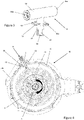
Figure 4 is a perspective cross-sectional view of the catcher ofFigure 3 in position in a central portion of the axle assembly ofFigure 2 ; -
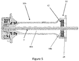
Figure 5 is a cross-sectional view of an arm portion of the axle assembly ofFigure 2 ; and -
Figure 6 is a front view of a brake plate that may be used with the axle assembly ofFigure 2 . - With reference to
Figure 1 , an embodiment of this disclosure includes amachine 1 which may be a working machine. In this embodiment, the working machine is a backhoe loader. In other embodiments, the working machine may be a telescopic handler, a skid steer loader, a wheel loader, or a telescopic wheel loader, for example. Such machines may be denoted as off-highway working machines. Themachine 1 includes amachine body 2 which may include, for example, anoperator cab 3 from which an operator can operate themachine 1. - In an embodiment, the
machine 1 has a ground engaging propulsion structure comprising a first axle assembly and a second axle assembly, each axle assembly being coupled to a pair of wheels (twowheels Figure 1 with onewheel 4 connected to the first axle assembly and onewheel 5 connected to the second axle assembly). The first axle assembly may be a front axle assembly and the second axle assembly may be a rear axle assembly. - Either or both of the first and second axle assemblies may be an axle assembly of the type illustrated in
Figure 2 . -
Figure 2 shows anaxle assembly 6 having anaxle housing 8 including a central portion, afirst arm portion 12a and asecond arm portion 12b. Each of the first andsecond arm portions 12a,b extend from thecentral portion 10 and house an driveshaft 7 (as shown inFigure 5 ). - With reference to
Figure 4 , the central portion houses agear 14 e.g. a crown gear. Thegear 14 is configured to rotate about an axis A in a direction indicated by arrow R. The central portion may house a differential gearing system (not shown). - The
central portion 10,first arm portion 12a andsecond arm portion 12b define a shared internal volume of the axle housing. This internal volume defines a shared lubricant reservoir within theaxle housing 8 when theaxle assembly 6 is in use. When in use, thecrown gear 14 is partially disposed in the lubricant reservoir. - Referring to
Figure 2 , theaxle assembly 6 includes aconduit assembly 16 which is configured to direct lubricant from thecentral portion 10 to the first andsecond arm portions 12a,b. The conduit assembly includes alubricant catcher 18 and first andsecond conduits 20a, b, wherein thelubricant catcher 18 is coupled to the first andsecond conduits 20a,b. Thefirst conduit 20a is configured to direct lubricant from thelubricant catcher 18 to a distal end of thefirst arm portion 12a. Similarly, thesecond conduit 20b is configured to direct lubricant from thecatcher 18 to a distal end of thesecond arm portion 12b. - With reference to
Figure 3 , thelubricant catcher 18 has aninlet 22 through which lubricant can enter theconduit assembly 16. As shown inFigure 4 , theinlet 22 of thelubricant catcher 18 is positioned in aninterior volume 24 of thecentral portion 10. - Again with reference to
Figure 4 , theconduit assembly 16 defines a flow path F which extends from theinlet 22 of thelubricant catcher 18 in a direction transverse to the axis of rotation A. The flow path F extends through awall 26 of thecentral portion housing 10 to an exterior of theaxle housing 8. - It will be appreciated that, as the
crown gear 14 rotates, lubricant from the lubricant reservoir will be propelled by thecrown gear 14 withininterior volume 24 of thecentral portion 10. Theinlet 22 of thelubricant catcher 18 is positioned in alignment with a trajectory of movement of the lubricant as it is propelled by thecrown gear 14, such that lubricant can enter theinlet 22. - From the view shown in
Figure 4 , movement of thecrown gear 14 is in a clockwise direction. Consequently, lubricant will also be propelled in a substantially clockwise direction. Theinlet 22 of thelubricant catcher 18 is located such that the inlet is open in a direction opposite to the direction of movement of the lubricant, i.e. facing a direction of rotation of thecrown gear 14. - With reference to
Figure 3 , thelubricant catcher 18 is substantially T-shaped and is designed as a single component made up of afirst pipe portion 32, forming the stem of the T-shape, i.e. the vertical portion of the T-shape, and asecond pipe portion 34, forming the top portion of the T-shape, i.e. the horizontal portion.. - The
first pipe portion 32 includes theinlet 22 at a first end and is coupled to thesecond pipe portion 34 at a second end. - The second pipe portion is coupled to the
first conduit 20a at afirst end 36a and is coupled to thesecond conduit 20b at asecond end 36b. Each of the first andsecond pipe portions second pipe portions - As can be seen in
Figure 4 , the flow path F extends from theinlet 22, along the length of thefirst pipe portion 32 to an inner wall of thesecond pipe portion 34. - The
first pipe portion 32 of thelubricant catcher 18 includes a fixingplate 30 for securing thecatcher 18 to thecentral portion housing 10. Thecatcher 18 and/orcentral portion 10 are configured such that thecatcher 18 can only be fitted to thecentral portion 10 in a single orientation. In the illustrated embodiment, this is achieved by providingbolt holes 30a in the fixingplate 30 of thecatcher 18 and corresponding bolt holes 31 in thewall 26 of thecentral portion 10. For example, the bolt holes 30a of the fixingplate 30 and corresponding bolt holes 31 of thecentral portion 10 are arranged to only line up for receipt of abolt 28 in a single direction. This ensures that thecatcher 18 can only be attached in a single orientation to ensure maximum flow of lubricant into theinlet 22. It will be appreciated that any other suitable means for restricting the orientation of the catcher may be applied. - The
inlet 22 of thecatcher 18 is formed as a cut out portion in a wall of thefirst pipe portion 32. The cut out portion forming theinlet 22 extends approximately halfway around the circumference of thefirst pipe portion 32. The end of thefirst pipe portion 32 in which the inlet is provided is closed by anend plate 33 e.g. a circular end plate. - In the illustrated embodiment, the first and
second pipe portions central portion 10, is maximised as much as possible given the dimensions of thecrown gear 14 and thecentral portion 10. - As illustrated in
Figure 4 , thelubricant catcher 18 is located at a rear side of thecentral portion 10 with respect to an intended direction of motion of the workingmachine 1. - In the illustrated embodiments, the first and
second conduits 20a, b, have a bore diameter of at least 10mm. In the illustrated embodiments, the bore diameter of the first andsecond conduits 20a,b is 14mm. - In the illustrated embodiment, as shown at
Figure 2 , for example, the first and second conduits have a circular cross section. In alternative embodiments, any other suitable cross section may be used. - As shown in
Figure 4 , thelubricant catcher 18 extends through awall 26 of thecentral portion 10 of theaxle housing 8 such that thesecond pipe portion 34 is positioned external to theaxle housing 8. The first andsecond conduits 20a,b are provided external to theaxle housing 8 and configured to extend from thecatcher 18 to a distal end of therespective arm portion 12a,b. - The
first conduit 20a extends from thecatcher 18 to thefirst arm portion 12a. Thefirst conduit 20a is connected to thefirst arm portion 12a via a hydraulic fitting 38a such that the interior of thefirst conduit 20a is in fluid communication with the interior of thefirst arm portion 12a. Similarly, thesecond conduit 20b extends from thecatcher 18 to thesecond arm portion 12b. Thesecond conduit 20b is connected to thesecond arm portion 12b by a second hydraulic fitting 38b, such that the interior of thesecond conduit 20b is in fluid communication with the interior of thesecond arm portion 12b. - In the illustrated embodiment, the
lubricant catcher 18 and the first andsecond conduits 20a,b are provided as separate components which are coupled together. In alternative embodiments, the catcher and conduits may be integrally formed. - The first and
second conduits 20a,b and thelubricant catcher 18 have substantially the same bore diameter. - In the illustrated embodiment, the first and
second conduits 20a,b are made of steel. In other embodiments, any suitable conductive material may be used. In further embodiments, any suitable material may be used. - In the illustrated embodiment, the
catcher 18 is made of steel. In alternative embodiments, any suitable conductive material may be used. In other embodiments, any suitable material may be used. - With reference to
Figure 5 , a cross sectional view of thesecond arm portion 12b is provided. Thefirst arm portion 12a has the same structure as thesecond arm portion 12b, so it will be appreciated that the description provided below in relation to thesecond arm portion 12b also applies to thefirst arm portion 12a. - The
second arm portion 12b of the axle housing defines aninterior volume 40b which is open to theinterior volume 24 of thecentral portion 10. In other words, theinterior volume 40b of thesecond arm portion 12b (and similarly, the interior volume of thefirst arm portion 12a) is in fluid communication with theinterior volume 24 of thecentral portion 10. - In use, the interior volumes of the first and
second arm portions 12a,b and theinterior volume 24 of thecentral portion 10 define a shared lubricant reservoir where lubricant is free to flow from theinterior volumes 40b of thearm portions 12a,b to theinterior volume 24 of thecentral portion 10 under gravity. - With reference to the
second arm portion 12b, lubricant that is directed to the distal end of thearm portions 12b by thesecond conduit 20b flows into theinterior volume 40b of thesecond arm portion 12b, and returns to theinterior volume 24 of thecentral portion 10 under gravity. No pump or other mechanism for moving the lubricant is required. The same applies to thefirst arm portion 12a. - As shown in
Figure 5 , theaxle assembly 6 further comprises awet brake system 42 which is designed to run in a bath of lubricant. Thewet brake system 42 is situated in thecentral portion 10 and has a first brake pack positioned on the side of thefirst arm portion 12a and asecond brake pack 44b positioned on the side of thesecond arm portion 12b (as shown inFigure 5 ). Eachbrake pack 44b includes a plurality of plates 46 (an example of which is shown inFigure 6 ), each of which having a series ofapertures 48 through which lubricant can flow to permit flow of lubricant through thebrake pack 44b. In this way, lubricant is free to flow from theinternal volume 40b of the second arm portion, to theinternal volume 24 of thecentral portion 10. The same applies to lubricant in thefirst arm portion 12a. - An
exemplary brake plate 46 is shown inFigure 6 . It will be appreciated that any suitable brake plate may be used. In some embodiments, the axle assembly does not include a brake system, or a brake system is provided external to the axle housing. - In the illustrated embodiment, a differential gear system (not shown) is provided between the brake packs within the
central portion 10. - In use, as the
crown gear 14 rotates, lubricant in the lubricant reservoir is propelled around theinterior volume 24 of thecentral portion 10. Thelubricant catcher 18 is positioned to intercept the trajectory of movement of the propelled lubricant such that lubricant enters theinlet 22 of thecatcher 18 and travels along flow path F of thecatcher 18. - Since the flow path F is arranged radially with respect to the
crown gear 14, interruption to the trajectory of the flow of lubricant is minimised and therefore flow of lubricant out of the central portion is maximised. If, for example the flow path were to be arranged axially with respect to thecrown gear 14, the lubricant propelled from thecrown gear 14 would be required to sharply change direction, thereby reducing flow of lubricant out of the central portion. - From here, lubricant travels from the catcher along the first and
second conduits 20a,b. In doing so, the lubricant is cooled to some extent, since theconduits 20a,b and thesecond pipe portion 34 are provided external to theaxle housing 8 and so benefit from cooling due to improved air flow. - The
conduits 20a,b direct lubricant to a distal end of therespective arm portion 12a,b and lubricant enters the respectiveinterior volume 40b of thearm portion 12a,b. Thearm portions 12a, b are typically cooler than thecentral portion 10 since they do not include heat generating components and are also better exposed to air flow. This has the effect of cooling the lubricant. In this way, the surface area of theaxle housing 8 can be used more effectively to improve temperature uniformity across theaxle assembly 6, leading to lower operating lubricant temperatures in thecentral portion 10, which improves lubricant life. - Once the lubricant has entered the
respective arm portion 12a, b, it travels under gravity towards theinterior volume 24 of the central portion, passing through the apertures of the brake plates of thebrake system 42. In other words, the shared lubricant reservoir results in "self-levelling" of the lubricant, such that lubricant returns to thecentral portion 10. From here, the rotation of thecrown gear 14 again propels lubricant in the lubricant reservoir, and the cycle continues. - In this way, effective cooling of the lubricant is achieved such that the temperature of the lubricant remains within acceptable limits.
- Although the disclosure has been described in relation to one or more embodiments, it will be appreciated that various changes or modifications can be made, without departing from the scope defined in the appended claims. For example, it will be appreciated that an axle housing including a single arm portion may be used, the conduit assembly may comprise a single conduit, and/or any suitable gear may propel lubricant in the central portion.
- In some embodiments, the axle assembly does not include internal wet brakes. In some embodiments, the axle assembly comprises a steering axle. In some embodiments, the axle assembly comprises external disc brakes at a distal end(s) of the axle assembly e.g. external to the axle housing.
Claims (15)
- An axle assembly for a working machine, the axle assembly having an axle housing comprising:a central portion housing a gear, wherein the gear is configured to rotate about an axis and is configured to be partially disposed in a lubricant reservoir, andat least one arm portion extending from the central portion, the arm portion housing at least one driveshaft,the axle assembly further comprising a conduit assembly configured to direct lubricant from the central portion to the arm portion, the conduit assembly comprising a lubricant catcher having an inlet disposed in an interior volume of the central portion.
- An axle assembly according to claim 1, wherein the conduit assembly defines a flow path extending from the inlet of the lubricant catcher in a direction transverse to the axis of rotation of the gear; optionally wherein the conduit assembly defines a flow path extending from the inlet of the lubricant catcher to an exterior of the axle housing, in a direction transverse to the axis of rotation of the gear.
- An axle assembly according to claim 1 or 2, wherein, in use, the gear is configured to move lubricant out of said lubricant reservoir, and wherein the inlet of the lubricant catcher is positioned in alignment with a trajectory of movement of said lubricant, such that lubricant can enter the inlet; optionally wherein the inlet is open in a direction opposite a direction of rotation to the gear.
- An axle assembly according to any preceding claim, wherein the lubricant catcher is configured such that it can only be fitted in a single orientation with respect the central portion of the axle housing; and/or wherein the lubricant catcher is located at a rear side of the central portion with respect to an intended direction of motion of the axle assembly when fitted to a machine.
- An axle assembly according to any preceding claim, wherein the conduit assembly comprises at least one conduit external to the axle housing, said conduit being configured to direct lubricant from the central portion to the arm portion; optionally wherein the lubricant catcher extends through a wall of the central portion of the axle housing and is coupled to said conduit; optionally wherein the lubricant catcher and/or conduit has a substantially constant bore diameter.
- An axle assembly according to claim 5, wherein the arm portion is a first arm portion and the conduit is a first conduit, wherein the axle assembly further comprises a second arm portion and the conduit assembly comprises a second conduit, wherein the second conduit is configured to direct lubricant from the central portion to the second arm portion.
- An axle assembly according to claim 5 or 6, wherein the or each conduit is made of a conductive material e.g. steel.
- An axle assembly according to any preceding claim, wherein the central portion and the or each arm portion define a shared lubricant reservoir, such that lubricant directed to the or each arm portion by the conduit assembly can return to the central portion under gravity.
- An axle assembly according to any preceding claim, wherein the axle assembly further comprises a wet brake system comprising one or more plates, wherein each of the one or more plates comprises an aperture configured to permit flow of lubricant therethrough.
- An axle assembly according to any preceding claim, wherein the conduit assembly is configured to direct lubricant from the central portion to a distal end of the or each arm portion.
- An axle assembly for a working machine, the axle assembly having an axle housing comprising:a central portion housing a gear which is configured to rotate about an axis and which is partially disposed in a lubricant reservoir, andat least one arm portion extending from the central portion, the arm portion housing at least one driveshaft,the axle assembly further comprising a conduit assembly configured to direct lubricant from the central portion to the arm portion, wherein an interior volume of the arm portion is in fluid communication with an interior volume of the central portion such that lubricant directed to the arm portion can return to the central portion under gravity.
- An axle assembly according to claim 11, wherein the central portion and the arm portion define a shared lubricant reservoir, such that lubricant directed to the arm portion by the conduit assembly returns to the central portion under gravity.
- An axle assembly according to claim 11 or 12, wherein the axle assembly further comprises a wet brake system comprising one or more plates, wherein each of the one or more plates comprises an aperture configured to permit flow of lubricant therethrough.
- An axle assembly according to any of claims 11 to 13, wherein the axle assembly does not comprise a pump and/or valve for directing the flow of lubricant.
- A working machine comprising an axle assembly according to any preceding claim.
Applications Claiming Priority (1)
| Application Number | Priority Date | Filing Date | Title |
|---|---|---|---|
| GB2105204.8A GB2606694B (en) | 2021-04-12 | 2021-04-12 | Axle assembly |
Publications (4)
| Publication Number | Publication Date |
|---|---|
| EP4075025A2 true EP4075025A2 (en) | 2022-10-19 |
| EP4075025A3 EP4075025A3 (en) | 2022-11-23 |
| EP4075025B1 EP4075025B1 (en) | 2024-03-27 |
| EP4075025C0 EP4075025C0 (en) | 2024-03-27 |
Family
ID=75949539
Family Applications (1)
| Application Number | Title | Priority Date | Filing Date |
|---|---|---|---|
| EP22167730.5A Active EP4075025B1 (en) | 2021-04-12 | 2022-04-11 | Axle assembly |
Country Status (4)
| Country | Link |
|---|---|
| US (1) | US11781638B2 (en) |
| EP (1) | EP4075025B1 (en) |
| ES (1) | ES2988717T3 (en) |
| GB (1) | GB2606694B (en) |
Cited By (1)
| Publication number | Priority date | Publication date | Assignee | Title |
|---|---|---|---|---|
| US12325262B1 (en) | 2023-12-12 | 2025-06-10 | Allison Transmission, Inc. | Lubrication distribution systems, powertrains incorporating the same, and methods of using the same |
Families Citing this family (3)
| Publication number | Priority date | Publication date | Assignee | Title |
|---|---|---|---|---|
| DE202021101206U1 (en) * | 2021-03-10 | 2022-06-15 | Dana Italia S.R.L. | Hydraulically suspended vehicle axle assembly and vehicle axle assembly incorporating this assembly |
| US20250074115A1 (en) * | 2023-08-28 | 2025-03-06 | Deere & Company | Vehicle, axle assembly, and method of modulating a temperature of lubricant in a vehicle axle assembly |
| IT202300019842A1 (en) * | 2023-09-26 | 2025-03-26 | Cnh Ind Italia Spa | LUBRICATION SYSTEM OF AN AGRICULTURAL TRACTOR PROPULSION SYSTEM |
Citations (1)
| Publication number | Priority date | Publication date | Assignee | Title |
|---|---|---|---|---|
| US6997284B1 (en) | 2001-06-26 | 2006-02-14 | Spicer Technology, Inc. | Lubricant cooling system for a motor vehicle axle |
Family Cites Families (24)
| Publication number | Priority date | Publication date | Assignee | Title |
|---|---|---|---|---|
| US924782A (en) * | 1908-06-15 | 1909-06-15 | American Circular Loom Co | Flexible conduit. |
| US1560391A (en) * | 1922-08-28 | 1925-11-03 | Jesse W Lobdell | Oil saver |
| DE1625891C2 (en) * | 1967-10-12 | 1975-02-06 | Daimler-Benz Ag, 7000 Stuttgart | Device for keeping the heat build-up in a final drive for motor vehicles |
| US3470767A (en) * | 1968-03-19 | 1969-10-07 | Billy C Gray | Oil transfer pump for vehicles |
| US4113067A (en) * | 1977-06-30 | 1978-09-12 | International Harvester Company | Cooling fluid circulation in an annular disc brake |
| DE3116595A1 (en) * | 1981-04-27 | 1982-11-11 | Daimler-Benz Ag, 7000 Stuttgart | Oil-lubricated differential gear of a vehicle drive axle with oil cooling |
| US4630711A (en) * | 1984-06-27 | 1986-12-23 | Societe Anonyme D.B.A. | Device for lubricating a geartrain |
| DE4023354C2 (en) * | 1990-07-23 | 1994-04-07 | Daimler Benz Ag | Driving axle for motor vehicles |
| US5316106A (en) * | 1993-05-07 | 1994-05-31 | Ford Motor Company | Lubricant cooling system for a motor vehicle axle |
| FR2744508B1 (en) * | 1996-02-07 | 1998-04-10 | Renault | ARRANGEMENT FOR THE LUBRICATION OF A GEAR TRAIN AND MOTOR VEHICLE GEARBOX COMPRISING SUCH AN ARRANGEMENT |
| US6499565B1 (en) * | 2000-03-15 | 2002-12-31 | Case Corporation | Apparatus and method for cooling an axle |
| US7178426B2 (en) * | 2004-09-23 | 2007-02-20 | Dana Corporation | Enhanced lubrication system for drive axle assemblies |
| US8714310B2 (en) * | 2007-08-22 | 2014-05-06 | Cnh America Llc | Axle cooling using hydraulic return oil |
| US9151377B2 (en) * | 2012-07-16 | 2015-10-06 | Caterpillar Inc. | Axle porting to legs |
| US9238386B2 (en) * | 2013-03-15 | 2016-01-19 | Caterpillar Inc. | Machine axle housing with integrated oil circulation system |
| GB2506509A (en) * | 2013-08-07 | 2014-04-02 | Daimler Ag | Vehicle gear lubrication filter having a separate catching element connected to the filter by a duct |
| JP6721482B2 (en) * | 2016-10-03 | 2020-07-15 | 株式会社小松製作所 | Axle assembly |
| US10190673B2 (en) * | 2016-11-30 | 2019-01-29 | Dana Heavy Vehicle Systems, Llc | Active oil management system for axles |
| CN214465983U (en) * | 2018-03-02 | 2021-10-22 | 德纳重型车辆系统集团有限责任公司 | Lubricant conditioning system and bridge assembly made with lubricant conditioning system |
| US20200016931A1 (en) * | 2018-07-12 | 2020-01-16 | Dana Heavy Vehicle Systems Group, Llc | Axle Assembly |
| CN109538743B (en) * | 2018-12-18 | 2024-03-26 | 精进电动科技股份有限公司 | Front bearing oil lubrication mechanism of water-cooled motor and motor driving assembly |
| DE102019209672A1 (en) * | 2019-07-02 | 2021-01-07 | Zf Friedrichshafen Ag | Pipeline, drive train unit with such a pipeline, as well as assembly methods |
| US11313453B2 (en) * | 2019-10-14 | 2022-04-26 | Ford Global Technologies, Llc | Methods and systems for a drive axle |
| US11421773B1 (en) * | 2021-02-15 | 2022-08-23 | Fca Us Llc | Vehicle drivetrain lubrication system |
-
2021
- 2021-04-12 GB GB2105204.8A patent/GB2606694B/en active Active
-
2022
- 2022-04-11 EP EP22167730.5A patent/EP4075025B1/en active Active
- 2022-04-11 ES ES22167730T patent/ES2988717T3/en active Active
- 2022-04-12 US US17/719,329 patent/US11781638B2/en active Active
Patent Citations (1)
| Publication number | Priority date | Publication date | Assignee | Title |
|---|---|---|---|---|
| US6997284B1 (en) | 2001-06-26 | 2006-02-14 | Spicer Technology, Inc. | Lubricant cooling system for a motor vehicle axle |
Cited By (1)
| Publication number | Priority date | Publication date | Assignee | Title |
|---|---|---|---|---|
| US12325262B1 (en) | 2023-12-12 | 2025-06-10 | Allison Transmission, Inc. | Lubrication distribution systems, powertrains incorporating the same, and methods of using the same |
Also Published As
| Publication number | Publication date |
|---|---|
| ES2988717T3 (en) | 2024-11-21 |
| GB2606694A (en) | 2022-11-23 |
| US11781638B2 (en) | 2023-10-10 |
| EP4075025B1 (en) | 2024-03-27 |
| GB202105204D0 (en) | 2021-05-26 |
| EP4075025A3 (en) | 2022-11-23 |
| GB2606694B (en) | 2024-03-27 |
| EP4075025C0 (en) | 2024-03-27 |
| US20220324256A1 (en) | 2022-10-13 |
Similar Documents
| Publication | Publication Date | Title |
|---|---|---|
| US11781638B2 (en) | Axle assembly | |
| US6871726B2 (en) | Axle assembly cooler using parallel flow paths | |
| US5540300A (en) | Drive axle assembly with lubricant cooling system | |
| EP3378548B1 (en) | An oil filter assembly | |
| US11181184B2 (en) | Drive assembly with passive pump lubrication | |
| CN103477111B (en) | device for supplying oil to the brakes | |
| JP6272616B2 (en) | Dump truck | |
| US10487897B2 (en) | Brake dust cover | |
| EP3406943B1 (en) | Axle assembly | |
| JP2016049916A (en) | In-wheel motor driving device | |
| CN111347835B (en) | Rotary heat exchanger and system thereof | |
| US9611930B2 (en) | Lubrication of power train components | |
| EP3581775B1 (en) | Road vehicle provided with a cooling system with "v" shaped dual radiator | |
| BR102022012475A2 (en) | WORK VEHICLE, AND, DRIVE AXLE ASSEMBLY | |
| JP4755617B2 (en) | In-wheel motor | |
| JP7423560B2 (en) | Work vehicle cooling system and work vehicle | |
| US20190100073A1 (en) | Duct assembly for a work vehicle | |
| JP7479459B2 (en) | Wheel device for vehicle | |
| CN104930170A (en) | Lubricating of power transmission system part | |
| JP4516878B2 (en) | Axle device | |
| JP3180637B2 (en) | Liquid-cooled disc brake | |
| JP2025059808A (en) | Electric motor and working machine | |
| JP5702322B2 (en) | Paddy field work vehicle | |
| JP7484113B2 (en) | Drive unit | |
| KR102470614B1 (en) | Oil Cooling Structure for Hydrostatic Transmission |
Legal Events
| Date | Code | Title | Description |
|---|---|---|---|
| PUAI | Public reference made under article 153(3) epc to a published international application that has entered the european phase |
Free format text: ORIGINAL CODE: 0009012 |
|
| STAA | Information on the status of an ep patent application or granted ep patent |
Free format text: STATUS: THE APPLICATION HAS BEEN PUBLISHED |
|
| AK | Designated contracting states |
Kind code of ref document: A2 Designated state(s): AL AT BE BG CH CY CZ DE DK EE ES FI FR GB GR HR HU IE IS IT LI LT LU LV MC MK MT NL NO PL PT RO RS SE SI SK SM TR |
|
| PUAL | Search report despatched |
Free format text: ORIGINAL CODE: 0009013 |
|
| AK | Designated contracting states |
Kind code of ref document: A3 Designated state(s): AL AT BE BG CH CY CZ DE DK EE ES FI FR GB GR HR HU IE IS IT LI LT LU LV MC MK MT NL NO PL PT RO RS SE SI SK SM TR |
|
| RIC1 | Information provided on ipc code assigned before grant |
Ipc: F16H 57/02 20120101ALI20221017BHEP Ipc: F16H 57/04 20100101AFI20221017BHEP |
|
| STAA | Information on the status of an ep patent application or granted ep patent |
Free format text: STATUS: REQUEST FOR EXAMINATION WAS MADE |
|
| 17P | Request for examination filed |
Effective date: 20230504 |
|
| RBV | Designated contracting states (corrected) |
Designated state(s): AL AT BE BG CH CY CZ DE DK EE ES FI FR GB GR HR HU IE IS IT LI LT LU LV MC MK MT NL NO PL PT RO RS SE SI SK SM TR |
|
| GRAP | Despatch of communication of intention to grant a patent |
Free format text: ORIGINAL CODE: EPIDOSNIGR1 |
|
| STAA | Information on the status of an ep patent application or granted ep patent |
Free format text: STATUS: GRANT OF PATENT IS INTENDED |
|
| INTG | Intention to grant announced |
Effective date: 20231204 |
|
| GRAS | Grant fee paid |
Free format text: ORIGINAL CODE: EPIDOSNIGR3 |
|
| GRAA | (expected) grant |
Free format text: ORIGINAL CODE: 0009210 |
|
| STAA | Information on the status of an ep patent application or granted ep patent |
Free format text: STATUS: THE PATENT HAS BEEN GRANTED |
|
| AK | Designated contracting states |
Kind code of ref document: B1 Designated state(s): AL AT BE BG CH CY CZ DE DK EE ES FI FR GB GR HR HU IE IS IT LI LT LU LV MC MK MT NL NO PL PT RO RS SE SI SK SM TR |
|
| REG | Reference to a national code |
Ref country code: GB Ref legal event code: FG4D |
|
| REG | Reference to a national code |
Ref country code: CH Ref legal event code: EP |
|
| REG | Reference to a national code |
Ref country code: DE Ref legal event code: R096 Ref document number: 602022002511 Country of ref document: DE |
|
| REG | Reference to a national code |
Ref country code: IE Ref legal event code: FG4D |
|
| U01 | Request for unitary effect filed |
Effective date: 20240327 |
|
| U07 | Unitary effect registered |
Designated state(s): AT BE BG DE DK EE FI FR IT LT LU LV MT NL PT SE SI Effective date: 20240408 |
|
| U20 | Renewal fee for the european patent with unitary effect paid |
Year of fee payment: 3 Effective date: 20240417 |
|
| PG25 | Lapsed in a contracting state [announced via postgrant information from national office to epo] |
Ref country code: GR Free format text: LAPSE BECAUSE OF FAILURE TO SUBMIT A TRANSLATION OF THE DESCRIPTION OR TO PAY THE FEE WITHIN THE PRESCRIBED TIME-LIMIT Effective date: 20240628 |
|
| PG25 | Lapsed in a contracting state [announced via postgrant information from national office to epo] |
Ref country code: HR Free format text: LAPSE BECAUSE OF FAILURE TO SUBMIT A TRANSLATION OF THE DESCRIPTION OR TO PAY THE FEE WITHIN THE PRESCRIBED TIME-LIMIT Effective date: 20240327 Ref country code: RS Free format text: LAPSE BECAUSE OF FAILURE TO SUBMIT A TRANSLATION OF THE DESCRIPTION OR TO PAY THE FEE WITHIN THE PRESCRIBED TIME-LIMIT Effective date: 20240627 |
|
| PG25 | Lapsed in a contracting state [announced via postgrant information from national office to epo] |
Ref country code: RS Free format text: LAPSE BECAUSE OF FAILURE TO SUBMIT A TRANSLATION OF THE DESCRIPTION OR TO PAY THE FEE WITHIN THE PRESCRIBED TIME-LIMIT Effective date: 20240627 Ref country code: NO Free format text: LAPSE BECAUSE OF FAILURE TO SUBMIT A TRANSLATION OF THE DESCRIPTION OR TO PAY THE FEE WITHIN THE PRESCRIBED TIME-LIMIT Effective date: 20240627 Ref country code: HR Free format text: LAPSE BECAUSE OF FAILURE TO SUBMIT A TRANSLATION OF THE DESCRIPTION OR TO PAY THE FEE WITHIN THE PRESCRIBED TIME-LIMIT Effective date: 20240327 Ref country code: GR Free format text: LAPSE BECAUSE OF FAILURE TO SUBMIT A TRANSLATION OF THE DESCRIPTION OR TO PAY THE FEE WITHIN THE PRESCRIBED TIME-LIMIT Effective date: 20240628 |
|
| PG25 | Lapsed in a contracting state [announced via postgrant information from national office to epo] |
Ref country code: IS Free format text: LAPSE BECAUSE OF FAILURE TO SUBMIT A TRANSLATION OF THE DESCRIPTION OR TO PAY THE FEE WITHIN THE PRESCRIBED TIME-LIMIT Effective date: 20240727 |
|
| PG25 | Lapsed in a contracting state [announced via postgrant information from national office to epo] |
Ref country code: SM Free format text: LAPSE BECAUSE OF FAILURE TO SUBMIT A TRANSLATION OF THE DESCRIPTION OR TO PAY THE FEE WITHIN THE PRESCRIBED TIME-LIMIT Effective date: 20240327 |
|
| PG25 | Lapsed in a contracting state [announced via postgrant information from national office to epo] |
Ref country code: CZ Free format text: LAPSE BECAUSE OF FAILURE TO SUBMIT A TRANSLATION OF THE DESCRIPTION OR TO PAY THE FEE WITHIN THE PRESCRIBED TIME-LIMIT Effective date: 20240327 |
|
| PG25 | Lapsed in a contracting state [announced via postgrant information from national office to epo] |
Ref country code: PL Free format text: LAPSE BECAUSE OF FAILURE TO SUBMIT A TRANSLATION OF THE DESCRIPTION OR TO PAY THE FEE WITHIN THE PRESCRIBED TIME-LIMIT Effective date: 20240327 |
|
| PG25 | Lapsed in a contracting state [announced via postgrant information from national office to epo] |
Ref country code: SK Free format text: LAPSE BECAUSE OF FAILURE TO SUBMIT A TRANSLATION OF THE DESCRIPTION OR TO PAY THE FEE WITHIN THE PRESCRIBED TIME-LIMIT Effective date: 20240327 |
|
| PG25 | Lapsed in a contracting state [announced via postgrant information from national office to epo] |
Ref country code: SM Free format text: LAPSE BECAUSE OF FAILURE TO SUBMIT A TRANSLATION OF THE DESCRIPTION OR TO PAY THE FEE WITHIN THE PRESCRIBED TIME-LIMIT Effective date: 20240327 Ref country code: SK Free format text: LAPSE BECAUSE OF FAILURE TO SUBMIT A TRANSLATION OF THE DESCRIPTION OR TO PAY THE FEE WITHIN THE PRESCRIBED TIME-LIMIT Effective date: 20240327 Ref country code: RO Free format text: LAPSE BECAUSE OF FAILURE TO SUBMIT A TRANSLATION OF THE DESCRIPTION OR TO PAY THE FEE WITHIN THE PRESCRIBED TIME-LIMIT Effective date: 20240327 Ref country code: PL Free format text: LAPSE BECAUSE OF FAILURE TO SUBMIT A TRANSLATION OF THE DESCRIPTION OR TO PAY THE FEE WITHIN THE PRESCRIBED TIME-LIMIT Effective date: 20240327 Ref country code: IS Free format text: LAPSE BECAUSE OF FAILURE TO SUBMIT A TRANSLATION OF THE DESCRIPTION OR TO PAY THE FEE WITHIN THE PRESCRIBED TIME-LIMIT Effective date: 20240727 Ref country code: CZ Free format text: LAPSE BECAUSE OF FAILURE TO SUBMIT A TRANSLATION OF THE DESCRIPTION OR TO PAY THE FEE WITHIN THE PRESCRIBED TIME-LIMIT Effective date: 20240327 |
|
| REG | Reference to a national code |
Ref country code: ES Ref legal event code: FG2A Ref document number: 2988717 Country of ref document: ES Kind code of ref document: T3 Effective date: 20241121 |
|
| REG | Reference to a national code |
Ref country code: DE Ref legal event code: R097 Ref document number: 602022002511 Country of ref document: DE |
|
| PG25 | Lapsed in a contracting state [announced via postgrant information from national office to epo] |
Ref country code: MC Free format text: LAPSE BECAUSE OF FAILURE TO SUBMIT A TRANSLATION OF THE DESCRIPTION OR TO PAY THE FEE WITHIN THE PRESCRIBED TIME-LIMIT Effective date: 20240327 |
|
| PG25 | Lapsed in a contracting state [announced via postgrant information from national office to epo] |
Ref country code: MC Free format text: LAPSE BECAUSE OF FAILURE TO SUBMIT A TRANSLATION OF THE DESCRIPTION OR TO PAY THE FEE WITHIN THE PRESCRIBED TIME-LIMIT Effective date: 20240327 |
|
| PLBE | No opposition filed within time limit |
Free format text: ORIGINAL CODE: 0009261 |
|
| STAA | Information on the status of an ep patent application or granted ep patent |
Free format text: STATUS: NO OPPOSITION FILED WITHIN TIME LIMIT |
|
| 26N | No opposition filed |
Effective date: 20250103 |
|
| PG25 | Lapsed in a contracting state [announced via postgrant information from national office to epo] |
Ref country code: IE Free format text: LAPSE BECAUSE OF NON-PAYMENT OF DUE FEES Effective date: 20240411 |
|
| U20 | Renewal fee for the european patent with unitary effect paid |
Year of fee payment: 4 Effective date: 20250416 |
|
| PGFP | Annual fee paid to national office [announced via postgrant information from national office to epo] |
Ref country code: ES Payment date: 20250530 Year of fee payment: 4 |
|
| PGFP | Annual fee paid to national office [announced via postgrant information from national office to epo] |
Ref country code: TR Payment date: 20250407 Year of fee payment: 4 |
|
| PG25 | Lapsed in a contracting state [announced via postgrant information from national office to epo] |
Ref country code: CY Free format text: LAPSE BECAUSE OF FAILURE TO SUBMIT A TRANSLATION OF THE DESCRIPTION OR TO PAY THE FEE WITHIN THE PRESCRIBED TIME-LIMIT; INVALID AB INITIO Effective date: 20220411 |
|
| PG25 | Lapsed in a contracting state [announced via postgrant information from national office to epo] |
Ref country code: HU Free format text: LAPSE BECAUSE OF FAILURE TO SUBMIT A TRANSLATION OF THE DESCRIPTION OR TO PAY THE FEE WITHIN THE PRESCRIBED TIME-LIMIT; INVALID AB INITIO Effective date: 20220411 |
|
| REG | Reference to a national code |
Ref country code: CH Ref legal event code: H13 Free format text: ST27 STATUS EVENT CODE: U-0-0-H10-H13 (AS PROVIDED BY THE NATIONAL OFFICE) Effective date: 20251125 |
|
| PG25 | Lapsed in a contracting state [announced via postgrant information from national office to epo] |
Ref country code: CH Free format text: LAPSE BECAUSE OF NON-PAYMENT OF DUE FEES Effective date: 20250430 |
|
| PGFP | Annual fee paid to national office [announced via postgrant information from national office to epo] |
Ref country code: GB Payment date: 20260323 Year of fee payment: 5 |