EP4074899A1 - Remote operation apparatus - Google Patents
Remote operation apparatus Download PDFInfo
- Publication number
- EP4074899A1 EP4074899A1 EP22160032.3A EP22160032A EP4074899A1 EP 4074899 A1 EP4074899 A1 EP 4074899A1 EP 22160032 A EP22160032 A EP 22160032A EP 4074899 A1 EP4074899 A1 EP 4074899A1
- Authority
- EP
- European Patent Office
- Prior art keywords
- housing
- seat
- remote operation
- operation apparatus
- holding
- Prior art date
- Legal status (The legal status is an assumption and is not a legal conclusion. Google has not performed a legal analysis and makes no representation as to the accuracy of the status listed.)
- Granted
Links
Images


Classifications
-
- E—FIXED CONSTRUCTIONS
- E02—HYDRAULIC ENGINEERING; FOUNDATIONS; SOIL SHIFTING
- E02F—DREDGING; SOIL-SHIFTING
- E02F9/00—Component parts of dredgers or soil-shifting machines, not restricted to one of the kinds covered by groups E02F3/00 - E02F7/00
- E02F9/20—Drives; Control devices
- E02F9/2025—Particular purposes of control systems not otherwise provided for
- E02F9/205—Remotely operated machines, e.g. unmanned vehicles
-
- E—FIXED CONSTRUCTIONS
- E02—HYDRAULIC ENGINEERING; FOUNDATIONS; SOIL SHIFTING
- E02F—DREDGING; SOIL-SHIFTING
- E02F9/00—Component parts of dredgers or soil-shifting machines, not restricted to one of the kinds covered by groups E02F3/00 - E02F7/00
- E02F9/20—Drives; Control devices
- E02F9/2058—Electric or electro-mechanical or mechanical control devices of vehicle sub-units
-
- E—FIXED CONSTRUCTIONS
- E02—HYDRAULIC ENGINEERING; FOUNDATIONS; SOIL SHIFTING
- E02F—DREDGING; SOIL-SHIFTING
- E02F9/00—Component parts of dredgers or soil-shifting machines, not restricted to one of the kinds covered by groups E02F3/00 - E02F7/00
- E02F9/16—Cabins, platforms, or the like, for drivers
- E02F9/166—Cabins, platforms, or the like, for drivers movable, tiltable or pivoting, e.g. movable seats, dampening arrangements of cabins
-
- E—FIXED CONSTRUCTIONS
- E02—HYDRAULIC ENGINEERING; FOUNDATIONS; SOIL SHIFTING
- E02F—DREDGING; SOIL-SHIFTING
- E02F9/00—Component parts of dredgers or soil-shifting machines, not restricted to one of the kinds covered by groups E02F3/00 - E02F7/00
- E02F9/20—Drives; Control devices
- E02F9/2004—Control mechanisms, e.g. control levers
-
- E—FIXED CONSTRUCTIONS
- E02—HYDRAULIC ENGINEERING; FOUNDATIONS; SOIL SHIFTING
- E02F—DREDGING; SOIL-SHIFTING
- E02F9/00—Component parts of dredgers or soil-shifting machines, not restricted to one of the kinds covered by groups E02F3/00 - E02F7/00
- E02F9/20—Drives; Control devices
- E02F9/2025—Particular purposes of control systems not otherwise provided for
-
- E—FIXED CONSTRUCTIONS
- E02—HYDRAULIC ENGINEERING; FOUNDATIONS; SOIL SHIFTING
- E02F—DREDGING; SOIL-SHIFTING
- E02F9/00—Component parts of dredgers or soil-shifting machines, not restricted to one of the kinds covered by groups E02F3/00 - E02F7/00
- E02F9/26—Indicating devices
-
- E—FIXED CONSTRUCTIONS
- E02—HYDRAULIC ENGINEERING; FOUNDATIONS; SOIL SHIFTING
- E02F—DREDGING; SOIL-SHIFTING
- E02F9/00—Component parts of dredgers or soil-shifting machines, not restricted to one of the kinds covered by groups E02F3/00 - E02F7/00
- E02F9/26—Indicating devices
- E02F9/261—Surveying the work-site to be treated
-
- E—FIXED CONSTRUCTIONS
- E02—HYDRAULIC ENGINEERING; FOUNDATIONS; SOIL SHIFTING
- E02F—DREDGING; SOIL-SHIFTING
- E02F9/00—Component parts of dredgers or soil-shifting machines, not restricted to one of the kinds covered by groups E02F3/00 - E02F7/00
- E02F9/26—Indicating devices
- E02F9/264—Sensors and their calibration for indicating the position of the work tool
-
- G—PHYSICS
- G05—CONTROLLING; REGULATING
- G05D—SYSTEMS FOR CONTROLLING OR REGULATING NON-ELECTRIC VARIABLES
- G05D1/00—Control of position, course, altitude or attitude of land, water, air or space vehicles, e.g. using automatic pilots
- G05D1/0011—Control of position, course, altitude or attitude of land, water, air or space vehicles, e.g. using automatic pilots associated with a remote control arrangement
- G05D1/0016—Control of position, course, altitude or attitude of land, water, air or space vehicles, e.g. using automatic pilots associated with a remote control arrangement characterised by the operator's input device
-
- G—PHYSICS
- G05—CONTROLLING; REGULATING
- G05D—SYSTEMS FOR CONTROLLING OR REGULATING NON-ELECTRIC VARIABLES
- G05D1/00—Control of position, course, altitude or attitude of land, water, air or space vehicles, e.g. using automatic pilots
- G05D1/0011—Control of position, course, altitude or attitude of land, water, air or space vehicles, e.g. using automatic pilots associated with a remote control arrangement
- G05D1/0038—Control of position, course, altitude or attitude of land, water, air or space vehicles, e.g. using automatic pilots associated with a remote control arrangement by providing the operator with simple or augmented images from one or more cameras located onboard the vehicle, e.g. tele-operation
-
- G—PHYSICS
- G05—CONTROLLING; REGULATING
- G05D—SYSTEMS FOR CONTROLLING OR REGULATING NON-ELECTRIC VARIABLES
- G05D1/00—Control of position, course, altitude or attitude of land, water, air or space vehicles, e.g. using automatic pilots
- G05D1/0011—Control of position, course, altitude or attitude of land, water, air or space vehicles, e.g. using automatic pilots associated with a remote control arrangement
- G05D1/005—Control of position, course, altitude or attitude of land, water, air or space vehicles, e.g. using automatic pilots associated with a remote control arrangement by providing the operator with signals other than visual, e.g. acoustic, haptic
Definitions
- the present invention relates to an improved operation apparatus for a remote operation of a work machine.
- Japanese Patent Laid-Open No. 2020-200660 a system has been developed to perform a work by remotely operating a work machine in a work site.
- a remote operation system of Japanese Patent Laid-Open No. 2020-200660 an operator boards a remote operation apparatus prepared in the same manner as in a maneuvering seat of an actual machine, to perform the remote operation.
- a maneuvering device comprises a monitor in front of the operator. The operator can see the same field of view as when the operator is in an actual vehicle, and can therefore maneuver the work machine as if the operator were in the actual vehicle.
- the remote operation apparatus comprises a monitor, a seat apparatus equipped with operation devices including a lever, and a housing on which the seat apparatus is mounted and fixed.
- the housing functions as a step for use when the operator gets on and off the seat apparatus, and is made sturdy so that the housing is not deformed when the operator stands on the housing, and boards the seat apparatus.
- an internal space of the housing is used to house electronic devices including a control PC which controls the maneuvering device.
- a housing having the above configuration is very heavy, and hard to move. Therefore, the housing needs to be moved by a plurality of persons, and has poor transportability. To solve this problem, it is considered that the transportability is improved simply by dividing the conventional housing into two small housings.
- a structure has concerns about stability when assembled and installed, and there is difficulty in acquiring the structure. Also, an operator sits on a seat fixed on the housing, and hence a gravity center height increases. If the housing is reduced in size in this state, a floor contact area is small for the high gravity center height, and this might lead to instability of a maneuvering device, such as falling of the maneuvering device.
- An object of the present invention which has been made to solve such problems, is to provide a remote operation apparatus which has an improved transportability and is excellent in stability and convenience.
- a remote operation apparatus is a remote operation apparatus which is operated by an operator to remotely operate a work executing machine, the remote operation apparatus comprising a seat including a seat part on which the operator sits, a seat holding device holding the seat, a drive device configured to move the seat, and a plurality of housings housing electronic equipment units including an arithmetic processing unit which performs entire processing of the remote operation apparatus, the plurality of housings include a first housing having an upper part to which the seat holding device is fixed, and a second housing in contact with and fixed to a part of the first housing in a front direction of the operator, and the drive device and the arithmetic processing unit are provided in the first housing.
- the remote operation apparatus 100 is an apparatus configured to remotely operate an unshown work machine which is in a place remote from the remote operation apparatus 100.
- the remote operation apparatus 100 There are not any restrictions on a type of work machine, which is, for example, a crawler excavator of construction machinery.
- the crawler excavator comprises a crawler type of lower running body, and an upper pivot body mounted on the lower running body via a pivot mechanism.
- the upper pivot body comprises a cab, and a work attachment including an arm with a bucket.
- the cab comprises a control mechanism which can remotely operate an operation lever and the like, and an imaging device which captures an image of a surrounding environment through a front window of the cab. The image captured by the imaging device is wirelessly transmitted to the remote operation apparatus 100, so that an operator can visually recognize the image.
- a control signal is transmitted from the remote operation apparatus 100, and the work machine is remotely operated.
- an acceleration sensor is mounted such as a gyro sensor which detects an acceleration in three-axis direction, and a detected acceleration signal is wirelessly transmitted to the remote operation apparatus 100.
- the remote operation apparatus 100 comprises a seat 10, a seat holding device 20, a drive device 30, a monitor device 50, a first housing 60, and a second housing 70.
- the seat 10 comprises a seat part 11, and arm rests 12 and 12 respectively provided on left and right sides of the seat 10.
- the left arm rest 12 includes an operation lever 13
- the right arm rest 12 includes an operation lever 13 and a display panel 14.
- the display panel 14 displays information indicating current states of the remotely operated work machine, the attachment and switches.
- the display panel 14 is, for example, a liquid crystal panel.
- the seat holding device 20 will be described with reference to FIGS. 3 and 4 .
- the seat holding device 20 holds the seat 10 on the first housing 60 in such a manner that the seat is movable in an up-down direction.
- the seat holding device 20 includes a holding shaft 21 and a horizontal plate 24.
- the horizontal plate 24 is a flat plate member, and is supported by the holding shaft 21 in a middle of a lower surface of the horizontal plate 24.
- the horizontal plate 24 is formed in a substantially triangular shape with one front side parallel in a left-right direction, and with a rear vertex cut with a line parallel to the one front side.
- the holding shaft 21 includes a double tube structure where two hollow tubes having slightly different diameters are combined as an outer cylinder 22 and an inner cylinder 23.
- the outer cylinder 22 has an upper end fixed to the lower surface of the horizontal plate 24, and the inner cylinder 23 has a lower end fixed to an upper surface of the first housing 60.
- the outer cylinder 22 and the inner cylinder 23 are not fixed to each other, and are relatively movable in the up-down direction.
- the inner cylinder 23 inserted into the outer cylinder 22 has an open upper end, and an internal space surrounded with the outer cylinder 22 and the inner cylinder 23 is airtightly filled with high pressure gas.
- the seat 10 and the operator have a mass supported with a repulsive force of the high pressure gas. Therefore, the seat 10 can be moved in the up-down direction in a strokable range by the drive device 30.
- the drive device 30 is a device which rotates the seat 10 and vibrates the seat 10, and which allows the operator to experience feeling of an operation on an actual machine.
- the drive device 30 includes a rotating device 31 and a vibrating device 41.
- the rotating device 31 includes a rotary shaft 32 disposed on an upper surface of the horizontal plate 24, a rotating plate 33 mounted on the rotary shaft 32, a driving force device 34 which generates a driving force to rotate the rotating plate 33, and a coupling member 36 which transmits, to the rotating plate 33, the driving force generated by the driving force device 34.
- the seat 10 is rotatably mounted on the rotating plate 33, and the rotating plate is rotated together with the seat 10 by the driving force transmitted from the driving force device 34.
- the driving force device 34 generates the driving force in response to the acceleration signal.
- a foot holding part 37 is disposed on which the operator puts feet when sitting on the seat 10.
- a running lever 15 is fixed to the foot holding part 37.
- the driving force device 34 is a linear drive device formed in a rectangular parallelepiped shape, and disposed on a rear end of the horizontal plate 24. There are not any restrictions on a drive form of the linear drive device, and the drive form may be any form such as an air cylinder, a combination of a rotary motor and ball screw, or a linear motor.
- the coupling member 36 couples the driving force device 34 to a rear end of the rotating plate 33.
- an unshown long hole is formed through which a drive shaft 35 of the driving force device 34 extends.
- the drive shaft 35 of the driving force device 34 linearly moves, and the coupling member 36 fixed to the rear end of the rotating plate 33 moves in an arc depending on the rotation of the rotating plate 33. Therefore, a position of the coupling member 36 is relatively moved away from a linear moving position of the driving force device 34, as a rotation angle of the rotating plate 33 increases in a front-rear direction of the remote operation apparatus 100. Therefore, when the coupling member 36 relatively moves to the drive shaft 35, the drive shaft 35 is configured to transmit the driving force of the driving force device 34, while relatively moving in the long hole.
- the coupling member 36 coupled to the rear end of the rotating plate 33 transmits the driving force from the driving force device 34 to the rotating plate 33, while change in positional relation between the coupling member 36 and the driving force device 34 depending on a rotation angle position of the rotating plate 33 is absorbed in the long hole of the coupling member 36.
- the vibrating device 41 includes a plurality of cylinders 42.
- the vibrating device 41 further includes a pressing plate 43 provided on an upper part of each of the cylinders 42, and a plurality of stopper members 44 each fixed to a lower surface of the pressing plate 43.
- Three cylinders 42 are provided in the first housing 60. Specifically, two cylinders are arranged on a front side and one cylinder is disposed on a rear side in accordance with the horizontal plate 24 formed in the substantially triangular shape.
- the upper part of the cylinder 42 is fixed substantially to a center of the pressing plate 43.
- the pressing plate 43 moves the cylinder 42 in the up-down direction, and presses the lower surface of the horizontal plate 24 to vibrate the seat 10, in response to the acceleration signal from the remotely operated work machine.
- a drive source of the cylinder 42 is, for example, an air pressure or an electric motor.
- each pressing plate 43 As shown in FIGS. 3 and 4 , as for a position of each pressing plate 43 in the up-down direction when the vibrating device 41 is not actuated, the pressing plate 43 is located at a lower end of a stroke range in the up-down direction.
- the lower surface of each pressing plate 43 is held by four stopper members 44 which are arranged to surround a periphery of the cylinder 42 under the pressing plate 43.
- the monitor device 50 will be described with reference to FIGS. 1 , 2 and 7 .
- the monitor device 50 includes a first screen part 51, a second screen part 52, a camera 53, and a monitor support part 54.
- Each of the first screen part 51 and the second screen part 52 includes three displays which are arranged continuously in the left-right direction.
- Each of the first screen part 51 and the second screen part 52 displays left, front and right images of the imaged work machine, and the operator performs the remote operation while visually recognizing the images in the monitor device 50.
- the monitor support part 54 includes two holding members 55 formed of hollow metal tubes and auxiliary members 57 respectively fixed to the holding members 55.
- the first screen part 51 and the second screen part 52 are fixed to upper portions of the holding members 55 with fixtures.
- each holding member 55 has one end 56 on a lower side which is securely fixed to a second front plate 73 of the second housing 70, and the holding member 55 is held to be perpendicular. Since the holding members 55 are fixed to the second front plate 73, it is not necessary to adjust and match a space between the seat 10 and the monitor device 50 every time the disassembled remote operation apparatus 100 is assembled again, and the space can be adjusted to a predetermined space by the assembling.
- Each auxiliary member 57 is fixed to the one end 56 of the holding member 55.
- Each auxiliary member 57 has a lower end in contact with a floor surface, and the auxiliary members 57 are configured to securely support the monitor device 50 that is a heavy object, together with the second housing 70.
- each fixture may be, for example, a fastener comprising a metal bracket formed in a U-shape and a bolt and nut.
- the fastener comprising the metal bracket and the bolt and nut, the remote operation apparatus 100 can be easily disassembled and assembled.
- a plurality of housings 60 and 70 will be described with reference to FIGS. 3 to 5 .
- the plurality of housings 60 and 70 are members having upper parts on which the seat 10 and the like are mounted, and housing electronic equipment units inside.
- a housing comprises the plurality of housings 60 and 70, i.e., the first housing 60 and the second housing 70.
- the first housing 60 and the second housing 70 have the same length in the left-right direction, and have different lengths in the front-rear direction and the up-down direction.
- the second housing 70 is connected to a front of the first housing 60.
- the first housing 60 is a rectangular parallelepiped body having an upper part on which the drive device 30, the seat holding device 20 and the seat 10 are mounted, and housing the electronic equipment units including a first arithmetic processing unit 81, a second arithmetic processing unit 82, and a seat controller 84.
- the first arithmetic processing unit 81 controls output of the monitor device 50, controls output of the display panel 14, recognizes input of the display panel, and recognizes inputs of the operation lever 13 and the running lever 15.
- the second arithmetic processing unit 82 manages communication between the remote operation apparatus 100 and the work machine that is a remote operation target, and passes a picture and an inclination signal, which are wirelessly transmitted from the work machine, to the first arithmetic processing unit 81.
- the second arithmetic processing unit also transmits, to the work machine, input information of input of an operation or the like recognized by the first arithmetic processing unit 81.
- the seat controller 84 controls the driving force device 34 and the vibrating device 41 based on the acceleration signal.
- a first bottom plate 61 At positions of six surfaces of the first housing 60 formed as the rectangular parallelepiped body, a first bottom plate 61, two first side plates 62 and 62, a first front plate 63, a first rear plate 64 and a first upper plate 65 are respectively arranged.
- the first bottom plate 61 formed in a rectangular shape has a lower surface under which casters 66 are arranged, each caster including an anti-movement tool around each corner of the first bottom plate 61.
- FIG. 6 shows electronic equipment units arranged in interiors of the first housing 60 and the second housing 70.
- the first arithmetic processing unit 81 and the second arithmetic processing unit 82 are arranged which are two comparatively heavy units.
- the first arithmetic processing unit 81 and the second arithmetic processing unit 82 are arranged to be balanced relative to a central position of the seat 10, in the left-right direction and the front-rear direction.
- the first arithmetic processing unit 81 and the second arithmetic processing unit 82 are arranged at substantially symmetrical positions to a central axis of the second housing in the left-right direction.
- the first arithmetic processing unit 81 is disposed at a distance K on one side with respect to the central axis in the left-right direction
- the second arithmetic processing unit 82 is disposed in a range of a distance from 0.8 K to 1.2 K (K ⁇ about 0.2 K) on the other side opposite to the first arithmetic processing unit 81.
- arrangement in the front-rear direction is similar to that in the left-right direction.
- the first arithmetic processing unit 81 is disposed at a distance L on one side with respect to a central axis in the front-rear direction
- the second arithmetic processing unit 82 is disposed in a range of a distance from 0.8 L to 1.2 L (L ⁇ about 0.2 L) on the other side opposite to the first arithmetic processing unit 81. Therefore, the first arithmetic processing unit 81 and the second arithmetic processing unit 82 are arranged at positions substantially close to a total gravity center position of a device such as the seat 10 disposed above the first housing 60 and the operator on the seat 10, in the left-right direction and front-rear direction, and the units are arranged to take a mass balance.
- the total gravity center position of the device such as the seat 10 and the operator on the seat 10 is a high position in the up-down direction of the second housing 70.
- the first arithmetic processing unit 81 and the second arithmetic processing unit 82 are arranged at low positions, which contributes to decrease in total gravity center height of the remote operation apparatus 100.
- a plurality of small cutouts 68 are provided in the first upper plate 65 and the first bottom plate 61.
- exhaust fans 69 and 69 are respectively provided on the left and right first side plates 62 and 62. Therefore, air introduced from the cutouts 68 flows while cooling the arithmetic processing unit 81 housed in the first housing 60, and the air is exhausted from the exhaust fans 69 and 69 arranged on the left and right first side plates 62 and 62.
- a first opening 67 is provided as an opening in the first front plate 63 of the first housing 60 which is a connection surface to the second housing 70.
- the second housing 70 houses a communication device 83 that is an electronic equipment unit in the interior of the second housing 70. At positions of six surfaces of the second housing 70 formed as a rectangular parallelepiped body, a second bottom plate 71, two second side plates 72 and 72, a second front plate 73, a second rear plate 74 and a second upper plate 75 are respectively arranged.
- the communication device 83 is a unit configured to communicate with the work machine that is the remote operation target, and is controlled by the second arithmetic processing unit 82.
- the communication device 83 comprises a transmitter/receiver, and a switching hub which connects the transmitter/receiver to another control equipment such as the first arithmetic processing unit 81 or the second arithmetic processing unit 82.
- the communication device 83 is connected to the other control equipment, for example, via a LAN cable.
- the second bottom plate 71 formed in a rectangular shape has a lower surface under which casters 66 are arranged, each caster including an anti-movement tool around each corner of the second bottom plate 71.
- a plurality of small cutouts 68 are provided in the second bottom plate 71. Note that in the second upper plate 75, any cutouts 68 are not provided. This prevents foreign matter from intruding into the second housing 70, because the second upper plate 75 is close to the foot holding part 37, and the second upper plate 75 is easy to get dust from above the second upper plate.
- the software of the remote operation apparatus 100 can be updated by connecting the commercial PC to the switching hub of the communication device 83.
- the communication device 83 that is a relay point of a communication signal is first examined, to confirm whether or not the signal reaches the communication device 83.
- a replacing work of the communication device 83 or a peripheral component such as a cable connected to the communication device 83 is performed.
- any components are not arranged above the second housing 70, and the second upper plate 75 is easily removable, which makes it easy to confirm the housed communication device 83. Therefore, an update work of the software and a maintenance work of the communication device 83 can be efficiently performed.
- the second housing 70 is a rectangular parallelepiped body similar to the first housing 60, but is formed to be longer than the first housing in the front-rear direction and to be lower than the first housing in the up-down direction.
- the second housing 70 has a height smaller than a height of the first housing 60 for the following reasons.
- a first reason is that in a case where the operator boards the remote operation apparatus 100, when the seat 10 has a higher seat surface, it is harder to get on and off the seat, and that it is easy to board by use of the second housing 70, which is lower than the first housing 60, as a boarding step.
- a second reason is that the remote operation apparatus 100 is configured to be hard to fall and to have high stability.
- the foot holding part 37 on which the operator puts feet is located above the second housing 70. It is necessary to prevent the second housing 70 from interfering with the foot holding part 37, and hence a height position of the foot holding part 37 can be lowered by suppressing a height of the second upper plate 75 of the second housing 70 down to a predetermined height.
- the seat 10 can be disposed at a low position, and a height of the whole remote operation apparatus 100 can be lowered. Therefore, the remote operation apparatus 100 is hard to fall, and improves the stability.
- the seat 10 rotates and vibrates during actuation of the remote operation apparatus 100, and hence the operator preferably feels more stability from a lower position than from a higher position of the seat 10 when sitting on the seat 10.
- the remote operation apparatus 100 improves the stability of the remote operation apparatus 100, and makes it easier for the operator to get on and off the remote operation apparatus 100, because the second upper plate 75 of the second housing 70 is disposed to be lower than the first upper plate 65 of the first housing 60.
- each of the left and right second side plates 72 and 72 one or more side plate openings 79 for weight reduction are provided.
- a second opening 77 is provided as an opening in the second rear plate 74 of the second housing 70 which is a connection surface to the first housing 60, as shown in FIG. 4 .
- FIG. 5 shows a front perspective view of the connection surfaces of the first housing 60 and the second housing 70 from which the second upper plate 75 is removed.
- the first opening 67 of the first housing 60 and the second opening 77 of the second housing 70 are formed to about the same size, and both the openings form one communicating opening.
- the first front plate 63 and the second rear plate 74 are fixed to four corners of the second rear plate 74 in plate parts in contact with each other, with fasteners such as unshown bolts and nuts.
- the first housing 60 and the second housing 70 can be easily separated only by removing the fasteners.
- a stud bolt may be provided in one plate, a bolt hole may be provided in the other plate, the stud bolt is inserted into the bolt hole, and then the plates can be fixed with a thumbscrew. In this case, both the housings can be coupled and separated without any tools.
- the first opening 67 is not formed in a part of the first front plate 63 above the second upper plate 75. This prevents foreign matter from intruding from the first front plate 63 into the first housing 60, the first front plate being located right under the foot holding part 37.
- part of air introduced through the cutouts 68 in the upper part of the first housing 60 flows through an opening formed of the first opening 67 and the second opening 77 into the second housing 70, and is exhausted from one or more side plate openings 79 provided in each of the left and right second side plates 72 and 72.
- This can improve coolability for the electronic equipment units by a simple technique without providing any additional cooling devices.
- dust or the like that intrudes into the first housing 60 and second housing 70 are conveyed via flow of cooling air and discharged from the side plate openings 79.
- the side plate openings 79 may be closed with a lightweight plate member such as an acrylic plate to prevent the foreign matter from intruding from the side plate openings 79.
- arrows A conceptually indicate the flow of part of air flowing through the interiors of the first housing 60 and second housing 70. Since the first opening 67 and the second opening 77 are provided, air can flow through the interiors of the first housing 60 and second housing 70 while efficiently cooling the interiors.
- the housing included in the remote operation apparatus 100 of the present invention is divided into two housings, transportability improves.
- the drive device 30 and the first and second arithmetic processing units 81 and 82 which are heavy objects, are arranged in the first housing 60 holding the seat 10 above. This can contribute to decrease in the gravity center height, and can provide the remote operation apparatus 100 with good weight balance.
- the first housing holding the seat 10 has a weight larger than that of the second housing 70, and the position of the center of gravity of the whole remote operation apparatus 100 can be located in the first housing 60.
- the comparatively heavy first housing 60 comprising the drive device 30 and the first arithmetic processing unit 81 is installed, and then the second housing 70, the seat 10 and others are installed. Since the position of the center of gravity of the whole remote operation apparatus 100 is located in the first housing 60, the weight balance can retain stability without being unbalanced.
- the remote operation apparatus comprises a foot holding part configured to hold feet of the operator put on the foot holding part
- the first housing includes a first upper plate that covers the upper part of the first housing
- the second housing includes a second upper plate that covers an upper part of the second housing
- the second upper plate is disposed at a position lower than a position of the first upper plate
- the foot holding part is located above the second upper plate and at a height equal to or less than a height of the seat part.
- the upper surface of the first housing to which a seat is fixed is made higher to keep a seat surface of an operator's chair at a high position, and the upper surface of the second housing on a foot side is made lower, so that a sufficient space for the operator's feet can be acquired and it is easy to get on and off the upper surface of the second housing from and to a floor surface on which a maneuvering device is installed. That is, the maneuvering device that is easy to get on and off and easy to maneuver can be obtained.
- the upper surface of the second housing is made lower, the foot holding part can be prevented from interfering with the second housing also in a case where the seat is noticeably inclined by a drive device.
- the first housing and the second housing respectively include openings in connection surfaces in contact with each other and the openings communicate with each other.
- coolability for electronic equipment units arranged in the first housing and the second housing can be improved without adding any devices, as compared with an original case where there are not any openings in connection surfaces in contact with each other.
- the second housing houses a communication device through which the arithmetic processing unit communicates with a device other than the arithmetic processing unit.
- the communication device with frequent maintenance is disposed in a centralized manner in one housing, so that maintainability can improve.
- the communication device is not disposed in the first housing to which the seat is fixed but is disposed in the second housing, and is therefore easy to maintain without being obstructed by the seat as compared with a case where the communication device is disposed in the first housing on which the seat is mounted.
- the remote operation apparatus comprises a monitor device which is disposed in front of the operator, and displays a front field of view of the machine received from the remotely operated machine, the monitor device includes a plurality of screen parts, and a plurality of holding members holding the plurality of screen parts, and each of the plurality of holding members has one end fixed to the second housing.
- a large monitor device is disposed in the centralized manner in the housing with a minimum holding mechanism, and can be therefore securely fixed. Furthermore, a distance between the housing and the monitor device can be kept constant, and a distance adjustment work is not required.
Landscapes
- Engineering & Computer Science (AREA)
- Mining & Mineral Resources (AREA)
- Civil Engineering (AREA)
- General Engineering & Computer Science (AREA)
- Structural Engineering (AREA)
- Physics & Mathematics (AREA)
- Remote Sensing (AREA)
- Radar, Positioning & Navigation (AREA)
- Aviation & Aerospace Engineering (AREA)
- General Physics & Mathematics (AREA)
- Automation & Control Theory (AREA)
- Computing Systems (AREA)
- Mathematical Physics (AREA)
- Theoretical Computer Science (AREA)
- Acoustics & Sound (AREA)
- Human Computer Interaction (AREA)
- Component Parts Of Construction Machinery (AREA)
- Selective Calling Equipment (AREA)
Abstract
Description
- The present invention relates to an improved operation apparatus for a remote operation of a work machine.
- In recent years, as disclosed in
Japanese Patent Laid-Open No. 2020-200660 Japanese Patent Laid-Open No. 2020-200660 - The remote operation apparatus comprises a monitor, a seat apparatus equipped with operation devices including a lever, and a housing on which the seat apparatus is mounted and fixed. The housing functions as a step for use when the operator gets on and off the seat apparatus, and is made sturdy so that the housing is not deformed when the operator stands on the housing, and boards the seat apparatus. Also, an internal space of the housing is used to house electronic devices including a control PC which controls the maneuvering device.
- However, a housing having the above configuration is very heavy, and hard to move. Therefore, the housing needs to be moved by a plurality of persons, and has poor transportability. To solve this problem, it is considered that the transportability is improved simply by dividing the conventional housing into two small housings. However, such a structure has concerns about stability when assembled and installed, and there is difficulty in acquiring the structure. Also, an operator sits on a seat fixed on the housing, and hence a gravity center height increases. If the housing is reduced in size in this state, a floor contact area is small for the high gravity center height, and this might lead to instability of a maneuvering device, such as falling of the maneuvering device.
- An object of the present invention, which has been made to solve such problems, is to provide a remote operation apparatus which has an improved transportability and is excellent in stability and convenience.
- A remote operation apparatus according to the present invention is a remote operation apparatus which is operated by an operator to remotely operate a work executing machine, the remote operation apparatus comprising a seat including a seat part on which the operator sits, a seat holding device holding the seat, a drive device configured to move the seat, and a plurality of housings housing electronic equipment units including an arithmetic processing unit which performs entire processing of the remote operation apparatus, the plurality of housings include a first housing having an upper part to which the seat holding device is fixed, and a second housing in contact with and fixed to a part of the first housing in a front direction of the operator, and the drive device and the arithmetic processing unit are provided in the first housing.
-
-
FIG. 1 is a left rear perspective view of a remote operation apparatus according to an embodiment of the present invention; -
FIG. 2 is a right rear perspective view of the remote operation apparatus ofFIG. 1 ; -
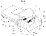
FIG. 3 is a left rear perspective view showing the remote operation apparatus ofFIG. 1 from which a seat and a monitor device are removed; -
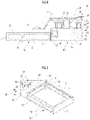
FIG. 4 is a left side view of the remote operation apparatus ofFIG. 3 ; -
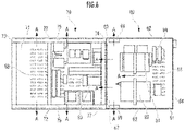
FIG. 5 is a front perspective view showing a connection portion between a second housing from which a second upper plate is removed and a first housing; -
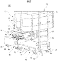
FIG. 6 is a plan view showing the first housing and the second housing from which a first upper plate and the second upper plate are removed, respectively; and -
FIG. 7 is a front perspective view of the remote operation apparatus ofFIG. 1 . - A
remote operation apparatus 100 according to the present invention will be described with reference toFIGS. 1 and2 . Theremote operation apparatus 100 is an apparatus configured to remotely operate an unshown work machine which is in a place remote from theremote operation apparatus 100. There are not any restrictions on a type of work machine, which is, for example, a crawler excavator of construction machinery. - The crawler excavator comprises a crawler type of lower running body, and an upper pivot body mounted on the lower running body via a pivot mechanism. The upper pivot body comprises a cab, and a work attachment including an arm with a bucket. The cab comprises a control mechanism which can remotely operate an operation lever and the like, and an imaging device which captures an image of a surrounding environment through a front window of the cab. The image captured by the imaging device is wirelessly transmitted to the
remote operation apparatus 100, so that an operator can visually recognize the image. When the operator operates theremote operation apparatus 100 while seeing the transmitted image, a control signal is transmitted from theremote operation apparatus 100, and the work machine is remotely operated. In the work machine, an acceleration sensor is mounted such as a gyro sensor which detects an acceleration in three-axis direction, and a detected acceleration signal is wirelessly transmitted to theremote operation apparatus 100. - The
remote operation apparatus 100 comprises aseat 10, aseat holding device 20, adrive device 30, amonitor device 50, afirst housing 60, and asecond housing 70. Theseat 10 comprises a seat part 11, and arm rests 12 and 12 respectively provided on left and right sides of theseat 10. Theleft arm rest 12 includes anoperation lever 13, and theright arm rest 12 includes anoperation lever 13 and adisplay panel 14. Thedisplay panel 14 displays information indicating current states of the remotely operated work machine, the attachment and switches. Thedisplay panel 14 is, for example, a liquid crystal panel. - The
seat holding device 20 will be described with reference toFIGS. 3 and4 . Theseat holding device 20 holds theseat 10 on thefirst housing 60 in such a manner that the seat is movable in an up-down direction. Theseat holding device 20 includes aholding shaft 21 and ahorizontal plate 24. Thehorizontal plate 24 is a flat plate member, and is supported by theholding shaft 21 in a middle of a lower surface of thehorizontal plate 24. Thehorizontal plate 24 is formed in a substantially triangular shape with one front side parallel in a left-right direction, and with a rear vertex cut with a line parallel to the one front side. - The
holding shaft 21 includes a double tube structure where two hollow tubes having slightly different diameters are combined as anouter cylinder 22 and aninner cylinder 23. Theouter cylinder 22 has an upper end fixed to the lower surface of thehorizontal plate 24, and theinner cylinder 23 has a lower end fixed to an upper surface of thefirst housing 60. Theouter cylinder 22 and theinner cylinder 23 are not fixed to each other, and are relatively movable in the up-down direction. Theinner cylinder 23 inserted into theouter cylinder 22 has an open upper end, and an internal space surrounded with theouter cylinder 22 and theinner cylinder 23 is airtightly filled with high pressure gas. Theseat 10 and the operator have a mass supported with a repulsive force of the high pressure gas. Therefore, theseat 10 can be moved in the up-down direction in a strokable range by thedrive device 30. - Next, the
drive device 30 will be described. Thedrive device 30 is a device which rotates theseat 10 and vibrates theseat 10, and which allows the operator to experience feeling of an operation on an actual machine. Thedrive device 30 includes arotating device 31 and avibrating device 41. - The
rotating device 31 includes arotary shaft 32 disposed on an upper surface of thehorizontal plate 24, a rotatingplate 33 mounted on therotary shaft 32, adriving force device 34 which generates a driving force to rotate therotating plate 33, and acoupling member 36 which transmits, to therotating plate 33, the driving force generated by thedriving force device 34. - The
seat 10 is rotatably mounted on therotating plate 33, and the rotating plate is rotated together with theseat 10 by the driving force transmitted from thedriving force device 34. Thedriving force device 34 generates the driving force in response to the acceleration signal. Also, in a front part of therotating plate 33, afoot holding part 37 is disposed on which the operator puts feet when sitting on theseat 10. Further, arunning lever 15 is fixed to thefoot holding part 37. Thedriving force device 34 is a linear drive device formed in a rectangular parallelepiped shape, and disposed on a rear end of thehorizontal plate 24. There are not any restrictions on a drive form of the linear drive device, and the drive form may be any form such as an air cylinder, a combination of a rotary motor and ball screw, or a linear motor. Thecoupling member 36 couples thedriving force device 34 to a rear end of the rotatingplate 33. - In an end of the
coupling member 36 on adriving force device 34 side, an unshown long hole is formed through which adrive shaft 35 of thedriving force device 34 extends. Thedrive shaft 35 of the drivingforce device 34 linearly moves, and thecoupling member 36 fixed to the rear end of therotating plate 33 moves in an arc depending on the rotation of therotating plate 33. Therefore, a position of thecoupling member 36 is relatively moved away from a linear moving position of the drivingforce device 34, as a rotation angle of therotating plate 33 increases in a front-rear direction of theremote operation apparatus 100. Therefore, when thecoupling member 36 relatively moves to thedrive shaft 35, thedrive shaft 35 is configured to transmit the driving force of the drivingforce device 34, while relatively moving in the long hole. Specifically, thecoupling member 36 coupled to the rear end of therotating plate 33 transmits the driving force from the drivingforce device 34 to therotating plate 33, while change in positional relation between the couplingmember 36 and the drivingforce device 34 depending on a rotation angle position of therotating plate 33 is absorbed in the long hole of thecoupling member 36. - The vibrating
device 41 includes a plurality ofcylinders 42. The vibratingdevice 41 further includes apressing plate 43 provided on an upper part of each of thecylinders 42, and a plurality ofstopper members 44 each fixed to a lower surface of thepressing plate 43. Threecylinders 42 are provided in thefirst housing 60. Specifically, two cylinders are arranged on a front side and one cylinder is disposed on a rear side in accordance with thehorizontal plate 24 formed in the substantially triangular shape. The upper part of thecylinder 42 is fixed substantially to a center of thepressing plate 43. Thepressing plate 43 moves thecylinder 42 in the up-down direction, and presses the lower surface of thehorizontal plate 24 to vibrate theseat 10, in response to the acceleration signal from the remotely operated work machine. A drive source of thecylinder 42 is, for example, an air pressure or an electric motor. - As shown in
FIGS. 3 and4 , as for a position of eachpressing plate 43 in the up-down direction when the vibratingdevice 41 is not actuated, thepressing plate 43 is located at a lower end of a stroke range in the up-down direction. When eachcylinder 42 is not actuated, the lower surface of eachpressing plate 43 is held by fourstopper members 44 which are arranged to surround a periphery of thecylinder 42 under thepressing plate 43. - The
monitor device 50 will be described with reference toFIGS. 1 ,2 and7 . Themonitor device 50 includes afirst screen part 51, asecond screen part 52, acamera 53, and amonitor support part 54. Each of thefirst screen part 51 and thesecond screen part 52 includes three displays which are arranged continuously in the left-right direction. Each of thefirst screen part 51 and thesecond screen part 52 displays left, front and right images of the imaged work machine, and the operator performs the remote operation while visually recognizing the images in themonitor device 50. Themonitor support part 54 includes two holdingmembers 55 formed of hollow metal tubes andauxiliary members 57 respectively fixed to the holdingmembers 55. Thefirst screen part 51 and thesecond screen part 52 are fixed to upper portions of the holdingmembers 55 with fixtures. - Also, each holding
member 55 has oneend 56 on a lower side which is securely fixed to a secondfront plate 73 of thesecond housing 70, and the holdingmember 55 is held to be perpendicular. Since the holdingmembers 55 are fixed to the secondfront plate 73, it is not necessary to adjust and match a space between theseat 10 and themonitor device 50 every time the disassembledremote operation apparatus 100 is assembled again, and the space can be adjusted to a predetermined space by the assembling. Eachauxiliary member 57 is fixed to the oneend 56 of the holdingmember 55. Eachauxiliary member 57 has a lower end in contact with a floor surface, and theauxiliary members 57 are configured to securely support themonitor device 50 that is a heavy object, together with thesecond housing 70. Note that there are not any restrictions on the fixtures with which the holdingmembers 55, themonitor device 50 and theauxiliary members 57 are fixed, and each fixture may be, for example, a fastener comprising a metal bracket formed in a U-shape and a bolt and nut. By use of the fastener comprising the metal bracket and the bolt and nut, theremote operation apparatus 100 can be easily disassembled and assembled. - A plurality of
housings FIGS. 3 to 5 . The plurality ofhousings seat 10 and the like are mounted, and housing electronic equipment units inside. To improve transportability of theremote operation apparatus 100, a housing comprises the plurality ofhousings first housing 60 and thesecond housing 70. Thefirst housing 60 and thesecond housing 70 have the same length in the left-right direction, and have different lengths in the front-rear direction and the up-down direction. Thesecond housing 70 is connected to a front of thefirst housing 60. - The
first housing 60 is a rectangular parallelepiped body having an upper part on which thedrive device 30, theseat holding device 20 and theseat 10 are mounted, and housing the electronic equipment units including a firstarithmetic processing unit 81, a secondarithmetic processing unit 82, and aseat controller 84. The firstarithmetic processing unit 81 controls output of themonitor device 50, controls output of thedisplay panel 14, recognizes input of the display panel, and recognizes inputs of theoperation lever 13 and the runninglever 15. The secondarithmetic processing unit 82 manages communication between theremote operation apparatus 100 and the work machine that is a remote operation target, and passes a picture and an inclination signal, which are wirelessly transmitted from the work machine, to the firstarithmetic processing unit 81. The second arithmetic processing unit also transmits, to the work machine, input information of input of an operation or the like recognized by the firstarithmetic processing unit 81. Theseat controller 84 controls the drivingforce device 34 and the vibratingdevice 41 based on the acceleration signal. At positions of six surfaces of thefirst housing 60 formed as the rectangular parallelepiped body, afirst bottom plate 61, twofirst side plates front plate 63, a firstrear plate 64 and a firstupper plate 65 are respectively arranged. Thefirst bottom plate 61 formed in a rectangular shape has a lower surface under which casters 66 are arranged, each caster including an anti-movement tool around each corner of thefirst bottom plate 61. -
FIG. 6 shows electronic equipment units arranged in interiors of thefirst housing 60 and thesecond housing 70. In thefirst housing 60, the firstarithmetic processing unit 81 and the secondarithmetic processing unit 82 are arranged which are two comparatively heavy units. In thefirst housing 60, the firstarithmetic processing unit 81 and the secondarithmetic processing unit 82 are arranged to be balanced relative to a central position of theseat 10, in the left-right direction and the front-rear direction. The firstarithmetic processing unit 81 and the secondarithmetic processing unit 82 are arranged at substantially symmetrical positions to a central axis of the second housing in the left-right direction. - For example, the first
arithmetic processing unit 81 is disposed at a distance K on one side with respect to the central axis in the left-right direction, and the secondarithmetic processing unit 82 is disposed in a range of a distance from 0.8 K to 1.2 K (K ± about 0.2 K) on the other side opposite to the firstarithmetic processing unit 81. Further, in thefirst housing 60, arrangement in the front-rear direction is similar to that in the left-right direction. For example, the firstarithmetic processing unit 81 is disposed at a distance L on one side with respect to a central axis in the front-rear direction, and the secondarithmetic processing unit 82 is disposed in a range of a distance from 0.8 L to 1.2 L (L ± about 0.2 L) on the other side opposite to the firstarithmetic processing unit 81. Therefore, the firstarithmetic processing unit 81 and the secondarithmetic processing unit 82 are arranged at positions substantially close to a total gravity center position of a device such as theseat 10 disposed above thefirst housing 60 and the operator on theseat 10, in the left-right direction and front-rear direction, and the units are arranged to take a mass balance. Furthermore, the total gravity center position of the device such as theseat 10 and the operator on theseat 10 is a high position in the up-down direction of thesecond housing 70. On the other hand, the firstarithmetic processing unit 81 and the secondarithmetic processing unit 82 are arranged at low positions, which contributes to decrease in total gravity center height of theremote operation apparatus 100. - In the first
upper plate 65 and thefirst bottom plate 61, a plurality ofsmall cutouts 68 are provided. On the left and rightfirst side plates exhaust fans cutouts 68 flows while cooling thearithmetic processing unit 81 housed in thefirst housing 60, and the air is exhausted from theexhaust fans first side plates FIG. 4 , in the firstfront plate 63 of thefirst housing 60 which is a connection surface to thesecond housing 70, afirst opening 67 is provided as an opening. - The
second housing 70 houses acommunication device 83 that is an electronic equipment unit in the interior of thesecond housing 70. At positions of six surfaces of thesecond housing 70 formed as a rectangular parallelepiped body, asecond bottom plate 71, twosecond side plates front plate 73, a secondrear plate 74 and a secondupper plate 75 are respectively arranged. Thecommunication device 83 is a unit configured to communicate with the work machine that is the remote operation target, and is controlled by the secondarithmetic processing unit 82. Thecommunication device 83 comprises a transmitter/receiver, and a switching hub which connects the transmitter/receiver to another control equipment such as the firstarithmetic processing unit 81 or the secondarithmetic processing unit 82. Thecommunication device 83 is connected to the other control equipment, for example, via a LAN cable. Thesecond bottom plate 71 formed in a rectangular shape has a lower surface under which casters 66 are arranged, each caster including an anti-movement tool around each corner of thesecond bottom plate 71. Also, in thesecond bottom plate 71, a plurality ofsmall cutouts 68 are provided. Note that in the secondupper plate 75, anycutouts 68 are not provided. This prevents foreign matter from intruding into thesecond housing 70, because the secondupper plate 75 is close to thefoot holding part 37, and the secondupper plate 75 is easy to get dust from above the second upper plate. - When updating software of the
remote operation apparatus 100, for example, it is necessary to connect a commercial PC to theremote operation apparatus 100, and rewrite the software mounted in the firstarithmetic processing unit 81 or the secondarithmetic processing unit 82. In this case, the software of theremote operation apparatus 100 can be updated by connecting the commercial PC to the switching hub of thecommunication device 83. - Also, in a case where malfunction occurs in the
remote operation apparatus 100 or at a time of regular inspection, thecommunication device 83 that is a relay point of a communication signal is first examined, to confirm whether or not the signal reaches thecommunication device 83. In a case where failure occurs in thecommunication device 83, a replacing work of thecommunication device 83 or a peripheral component such as a cable connected to thecommunication device 83 is performed. - Any components are not arranged above the
second housing 70, and the secondupper plate 75 is easily removable, which makes it easy to confirm the housedcommunication device 83. Therefore, an update work of the software and a maintenance work of thecommunication device 83 can be efficiently performed. - The
second housing 70 is a rectangular parallelepiped body similar to thefirst housing 60, but is formed to be longer than the first housing in the front-rear direction and to be lower than the first housing in the up-down direction. Thesecond housing 70 has a height smaller than a height of thefirst housing 60 for the following reasons. A first reason is that in a case where the operator boards theremote operation apparatus 100, when theseat 10 has a higher seat surface, it is harder to get on and off the seat, and that it is easy to board by use of thesecond housing 70, which is lower than thefirst housing 60, as a boarding step. - A second reason is that the
remote operation apparatus 100 is configured to be hard to fall and to have high stability. As shown inFIG. 4 , thefoot holding part 37 on which the operator puts feet is located above thesecond housing 70. It is necessary to prevent thesecond housing 70 from interfering with thefoot holding part 37, and hence a height position of thefoot holding part 37 can be lowered by suppressing a height of the secondupper plate 75 of thesecond housing 70 down to a predetermined height. As a result, theseat 10 can be disposed at a low position, and a height of the wholeremote operation apparatus 100 can be lowered. Therefore, theremote operation apparatus 100 is hard to fall, and improves the stability. In particular, theseat 10 rotates and vibrates during actuation of theremote operation apparatus 100, and hence the operator preferably feels more stability from a lower position than from a higher position of theseat 10 when sitting on theseat 10. Theremote operation apparatus 100 improves the stability of theremote operation apparatus 100, and makes it easier for the operator to get on and off theremote operation apparatus 100, because the secondupper plate 75 of thesecond housing 70 is disposed to be lower than the firstupper plate 65 of thefirst housing 60. - In each of the left and right
second side plates side plate openings 79 for weight reduction are provided. Further, in the secondrear plate 74 of thesecond housing 70 which is a connection surface to thefirst housing 60, as shown inFIG. 4 , asecond opening 77 is provided as an opening.FIG. 5 shows a front perspective view of the connection surfaces of thefirst housing 60 and thesecond housing 70 from which the secondupper plate 75 is removed. Thefirst opening 67 of thefirst housing 60 and thesecond opening 77 of thesecond housing 70 are formed to about the same size, and both the openings form one communicating opening. - The first
front plate 63 and the secondrear plate 74 are fixed to four corners of the secondrear plate 74 in plate parts in contact with each other, with fasteners such as unshown bolts and nuts. During transport, thefirst housing 60 and thesecond housing 70 can be easily separated only by removing the fasteners. Alternatively, to facilitate the work, a stud bolt may be provided in one plate, a bolt hole may be provided in the other plate, the stud bolt is inserted into the bolt hole, and then the plates can be fixed with a thumbscrew. In this case, both the housings can be coupled and separated without any tools. Note that as shown inFIG. 5 , thefirst opening 67 is not formed in a part of the firstfront plate 63 above the secondupper plate 75. This prevents foreign matter from intruding from the firstfront plate 63 into thefirst housing 60, the first front plate being located right under thefoot holding part 37. - According to a communication structure of the
first opening 67 with thesecond opening 77, part of air introduced through thecutouts 68 in the upper part of thefirst housing 60 flows through an opening formed of thefirst opening 67 and thesecond opening 77 into thesecond housing 70, and is exhausted from one or moreside plate openings 79 provided in each of the left and rightsecond side plates first housing 60 andsecond housing 70 are conveyed via flow of cooling air and discharged from theside plate openings 79. Alternatively, theside plate openings 79 may be closed with a lightweight plate member such as an acrylic plate to prevent the foreign matter from intruding from theside plate openings 79. - In
FIG. 6 , arrows A conceptually indicate the flow of part of air flowing through the interiors of thefirst housing 60 andsecond housing 70. Since thefirst opening 67 and thesecond opening 77 are provided, air can flow through the interiors of thefirst housing 60 andsecond housing 70 while efficiently cooling the interiors. - Since the housing included in the
remote operation apparatus 100 of the present invention is divided into two housings, transportability improves. With the improvement in transportability, in theremote operation apparatus 100 in which the sitting operator has a high gravity center height and a weight tends to be unbalanced, thedrive device 30 and the first and secondarithmetic processing units first housing 60 holding theseat 10 above. This can contribute to decrease in the gravity center height, and can provide theremote operation apparatus 100 with good weight balance. Also, the first housing holding theseat 10 has a weight larger than that of thesecond housing 70, and the position of the center of gravity of the wholeremote operation apparatus 100 can be located in thefirst housing 60. During assembling and installing of theremote operation apparatus 100, the comparatively heavyfirst housing 60 comprising thedrive device 30 and the firstarithmetic processing unit 81 is installed, and then thesecond housing 70, theseat 10 and others are installed. Since the position of the center of gravity of the wholeremote operation apparatus 100 is located in thefirst housing 60, the weight balance can retain stability without being unbalanced. - Also, it is preferable that the remote operation apparatus according to the present invention comprises a foot holding part configured to hold feet of the operator put on the foot holding part, the first housing includes a first upper plate that covers the upper part of the first housing, the second housing includes a second upper plate that covers an upper part of the second housing, the second upper plate is disposed at a position lower than a position of the first upper plate, and the foot holding part is located above the second upper plate and at a height equal to or less than a height of the seat part.
- According to the present invention, in upper surfaces of two housings, the upper surface of the first housing to which a seat is fixed is made higher to keep a seat surface of an operator's chair at a high position, and the upper surface of the second housing on a foot side is made lower, so that a sufficient space for the operator's feet can be acquired and it is easy to get on and off the upper surface of the second housing from and to a floor surface on which a maneuvering device is installed. That is, the maneuvering device that is easy to get on and off and easy to maneuver can be obtained. Further, since the upper surface of the second housing is made lower, the foot holding part can be prevented from interfering with the second housing also in a case where the seat is noticeably inclined by a drive device.
- Further, in the remote operation apparatus according to the present invention, it is preferable that the first housing and the second housing respectively include openings in connection surfaces in contact with each other and the openings communicate with each other.
- In the present invention, according to a structure where the respective openings in the first housing and the second housing communicate with each other to allow cooling air to flow through the housings, coolability for electronic equipment units arranged in the first housing and the second housing can be improved without adding any devices, as compared with an original case where there are not any openings in connection surfaces in contact with each other.
- Also, in the remote operation apparatus according to the present invention, it is preferable that the second housing houses a communication device through which the arithmetic processing unit communicates with a device other than the arithmetic processing unit.
- According to the present invention, the communication device with frequent maintenance is disposed in a centralized manner in one housing, so that maintainability can improve. The communication device is not disposed in the first housing to which the seat is fixed but is disposed in the second housing, and is therefore easy to maintain without being obstructed by the seat as compared with a case where the communication device is disposed in the first housing on which the seat is mounted.
- Also, it is preferable that the remote operation apparatus according to the present invention comprises a monitor device which is disposed in front of the operator, and displays a front field of view of the machine received from the remotely operated machine, the monitor device includes a plurality of screen parts, and a plurality of holding members holding the plurality of screen parts, and each of the plurality of holding members has one end fixed to the second housing.
- According to the present invention, a large monitor device is disposed in the centralized manner in the housing with a minimum holding mechanism, and can be therefore securely fixed. Furthermore, a distance between the housing and the monitor device can be kept constant, and a distance adjustment work is not required.
-
- 10
- seat
- 11
- seat part
- 20
- seat holding device
- 30
- drive device
- 37
- foot holding part
- 50
- monitor device
- 51
- first screen part
- 52
- second screen part
- 55
- holding member
- 56
- one end
- 65
- first upper plate
- 75
- second upper plate
- 60
- first housing
- 70
- second housing
- 81
- first arithmetic processing unit
- 82
- second arithmetic processing unit
- 83
- communication device
- 100
- remote operation apparatus
Claims (5)
- A remote operation apparatus which is operated by an operator to remotely operate a work executing machine, the remote operation apparatus comprising:a seat including a seat part on which the operator sits;a seat holding device holding the seat;a drive device configured to move the seat; anda plurality of housings housing electronic equipment units including an arithmetic processing unit which performs entire processing of the remote operation apparatus, whereinthe plurality of housings include a first housing having an upper part to which the seat holding device is fixed, and a second housing in contact with and fixed to a part of the first housing in a front direction of the operator, andthe drive device and the arithmetic processing unit are provided in the first housing.
- The remote operation apparatus according to claim 1, further comprisinga foot holding part configured to hold feet of the operator put on the foot holding part, whereinthe first housing includes a first upper plate that covers the upper part of the first housing,the second housing includes a second upper plate that covers an upper part of the second housing,the second upper plate is disposed at a position lower than a position of the first upper plate, andthe foot holding part is located above the second upper plate and at a height equal to or less than a height of the seat part.
- The remote operation apparatus according to claim 1 or 2, whereinthe first housing and the second housing respectively include openings in connection surfaces in contact with each other, andthe openings communicate with each other.
- The remote operation apparatus according to anyone of claims 1 to 3, wherein the second housing houses a communication device through which the arithmetic processing unit communicates with a device other than the arithmetic processing unit.
- The remote operation apparatus according to anyone of claims 1 to 4, further comprisinga monitor device which is disposed in front of the operator, and displays a front field of view of the machine received from the remotely operated machine, whereinthe monitor device includes a plurality of screen parts, and a plurality of holding members holding the plurality of screen parts, andeach of the plurality of holding members has one end fixed to the second housing.
Applications Claiming Priority (1)
| Application Number | Priority Date | Filing Date | Title |
|---|---|---|---|
| JP2021058148A JP7517224B2 (en) | 2021-03-30 | 2021-03-30 | Remote Control Device |
Publications (2)
| Publication Number | Publication Date |
|---|---|
| EP4074899A1 true EP4074899A1 (en) | 2022-10-19 |
| EP4074899B1 EP4074899B1 (en) | 2023-06-07 |
Family
ID=80628920
Family Applications (1)
| Application Number | Title | Priority Date | Filing Date |
|---|---|---|---|
| EP22160032.3A Active EP4074899B1 (en) | 2021-03-30 | 2022-03-03 | Remote operation apparatus |
Country Status (4)
| Country | Link |
|---|---|
| US (1) | US20220316182A1 (en) |
| EP (1) | EP4074899B1 (en) |
| JP (1) | JP7517224B2 (en) |
| CN (1) | CN115217175A (en) |
Cited By (2)
| Publication number | Priority date | Publication date | Assignee | Title |
|---|---|---|---|---|
| IT202300010302A1 (en) * | 2023-05-22 | 2024-11-22 | Amog S R L | VISIBILITY IMPROVEMENT SYSTEM IN WORK VEHICLES |
| GB2631912A (en) * | 2023-04-23 | 2025-01-22 | Hamersham Ltd | Uncrewed land vehicle remote control operator unit |
Citations (5)
| Publication number | Priority date | Publication date | Assignee | Title |
|---|---|---|---|---|
| CN106444734A (en) * | 2016-10-31 | 2017-02-22 | 成都紫瑞青云航空宇航技术有限公司 | Portable ground station |
| US20170308074A1 (en) * | 2016-04-20 | 2017-10-26 | Caterpillar Inc. | Remote operator station for a machine |
| US20170328030A1 (en) * | 2015-01-28 | 2017-11-16 | Hitachi, Ltd. | Operation system of working machine |
| US9982415B2 (en) * | 2014-04-09 | 2018-05-29 | Hitachi, Ltd. | Remote control system for work machines |
| JP2020200660A (en) | 2019-06-10 | 2020-12-17 | コベルコ建機株式会社 | Remote operation system and remote operation server |
Family Cites Families (3)
| Publication number | Priority date | Publication date | Assignee | Title |
|---|---|---|---|---|
| US7887130B1 (en) * | 2008-08-27 | 2011-02-15 | Lockheed Martin Corporation | Workstation |
| JP5180248B2 (en) * | 2010-03-09 | 2013-04-10 | 株式会社神戸製鋼所 | Support structure for hydraulic piping and work machine equipped with the same |
| CN210194735U (en) * | 2019-05-21 | 2020-03-27 | 龙工(福建)机械有限公司 | Movable loader guide operating mechanism |
-
2021
- 2021-03-30 JP JP2021058148A patent/JP7517224B2/en active Active
-
2022
- 2022-03-03 EP EP22160032.3A patent/EP4074899B1/en active Active
- 2022-03-04 US US17/686,948 patent/US20220316182A1/en not_active Abandoned
- 2022-03-22 CN CN202210284815.1A patent/CN115217175A/en active Pending
Patent Citations (5)
| Publication number | Priority date | Publication date | Assignee | Title |
|---|---|---|---|---|
| US9982415B2 (en) * | 2014-04-09 | 2018-05-29 | Hitachi, Ltd. | Remote control system for work machines |
| US20170328030A1 (en) * | 2015-01-28 | 2017-11-16 | Hitachi, Ltd. | Operation system of working machine |
| US20170308074A1 (en) * | 2016-04-20 | 2017-10-26 | Caterpillar Inc. | Remote operator station for a machine |
| CN106444734A (en) * | 2016-10-31 | 2017-02-22 | 成都紫瑞青云航空宇航技术有限公司 | Portable ground station |
| JP2020200660A (en) | 2019-06-10 | 2020-12-17 | コベルコ建機株式会社 | Remote operation system and remote operation server |
Cited By (2)
| Publication number | Priority date | Publication date | Assignee | Title |
|---|---|---|---|---|
| GB2631912A (en) * | 2023-04-23 | 2025-01-22 | Hamersham Ltd | Uncrewed land vehicle remote control operator unit |
| IT202300010302A1 (en) * | 2023-05-22 | 2024-11-22 | Amog S R L | VISIBILITY IMPROVEMENT SYSTEM IN WORK VEHICLES |
Also Published As
| Publication number | Publication date |
|---|---|
| EP4074899B1 (en) | 2023-06-07 |
| CN115217175A (en) | 2022-10-21 |
| JP2022154888A (en) | 2022-10-13 |
| JP7517224B2 (en) | 2024-07-17 |
| US20220316182A1 (en) | 2022-10-06 |
Similar Documents
| Publication | Publication Date | Title |
|---|---|---|
| EP4074899B1 (en) | Remote operation apparatus | |
| JP3398009B2 (en) | Remote control system | |
| JP7559696B2 (en) | Remote Control Device | |
| CN101184169A (en) | Camera position control interface | |
| WO2015155845A1 (en) | Remote control system for work machines | |
| US20220220706A1 (en) | Remote operation system | |
| CN111386369A (en) | Construction machine | |
| CN113544337A (en) | Operating mechanism for working machine and working machine provided with same | |
| US11898332B1 (en) | Adjusting camera bandwidth based on machine operation | |
| US20220316180A1 (en) | Remote driving device and operation mechanism for work machine | |
| CN115522593A (en) | display device | |
| US11959250B2 (en) | Manipulation mechanism for work machine and work machine equipped with same | |
| CN223993057U (en) | Remote cockpit | |
| CN221291328U (en) | Remote control cockpit | |
| JP7723544B2 (en) | Remote control training device | |
| JPH06173446A (en) | Operating console for construction site | |
| EP3933120B1 (en) | Work machine operation mechanism, and work machine provided with same | |
| EP4421246A1 (en) | Electronic device support mechanism and construction machine comprising electronic device support mechanism | |
| JP7205965B1 (en) | A machine that moves a lever and a computer connected to the machine | |
| JP7727583B2 (en) | Roller compaction machine | |
| CN217578070U (en) | Sucker accessory remote control system and engineering vehicle | |
| CN121816448A (en) | Construction machinery and operating systems | |
| JP2024065874A (en) | Work Machine | |
| JP2026083302A (en) | Work vehicles | |
| WO2023223680A1 (en) | Imaging mechanism, work machine equipped with imaging mechanism, and work machine remote control system for remotely controlling work machine |
Legal Events
| Date | Code | Title | Description |
|---|---|---|---|
| PUAI | Public reference made under article 153(3) epc to a published international application that has entered the european phase |
Free format text: ORIGINAL CODE: 0009012 |
|
| STAA | Information on the status of an ep patent application or granted ep patent |
Free format text: STATUS: THE APPLICATION HAS BEEN PUBLISHED |
|
| AK | Designated contracting states |
Kind code of ref document: A1 Designated state(s): AL AT BE BG CH CY CZ DE DK EE ES FI FR GB GR HR HU IE IS IT LI LT LU LV MC MK MT NL NO PL PT RO RS SE SI SK SM TR |
|
| STAA | Information on the status of an ep patent application or granted ep patent |
Free format text: STATUS: REQUEST FOR EXAMINATION WAS MADE |
|
| 17P | Request for examination filed |
Effective date: 20221221 |
|
| RBV | Designated contracting states (corrected) |
Designated state(s): AL AT BE BG CH CY CZ DE DK EE ES FI FR GB GR HR HU IE IS IT LI LT LU LV MC MK MT NL NO PL PT RO RS SE SI SK SM TR |
|
| GRAP | Despatch of communication of intention to grant a patent |
Free format text: ORIGINAL CODE: EPIDOSNIGR1 |
|
| STAA | Information on the status of an ep patent application or granted ep patent |
Free format text: STATUS: GRANT OF PATENT IS INTENDED |
|
| INTG | Intention to grant announced |
Effective date: 20230214 |
|
| GRAS | Grant fee paid |
Free format text: ORIGINAL CODE: EPIDOSNIGR3 |
|
| GRAA | (expected) grant |
Free format text: ORIGINAL CODE: 0009210 |
|
| STAA | Information on the status of an ep patent application or granted ep patent |
Free format text: STATUS: THE PATENT HAS BEEN GRANTED |
|
| AK | Designated contracting states |
Kind code of ref document: B1 Designated state(s): AL AT BE BG CH CY CZ DE DK EE ES FI FR GB GR HR HU IE IS IT LI LT LU LV MC MK MT NL NO PL PT RO RS SE SI SK SM TR |
|
| REG | Reference to a national code |
Ref country code: GB Ref legal event code: FG4D |
|
| REG | Reference to a national code |
Ref country code: CH Ref legal event code: EP Ref country code: AT Ref legal event code: REF Ref document number: 1575379 Country of ref document: AT Kind code of ref document: T Effective date: 20230615 |
|
| REG | Reference to a national code |
Ref country code: DE Ref legal event code: R096 Ref document number: 602022000110 Country of ref document: DE |
|
| REG | Reference to a national code |
Ref country code: LT Ref legal event code: MG9D |
|
| REG | Reference to a national code |
Ref country code: NL Ref legal event code: MP Effective date: 20230607 |
|
| PG25 | Lapsed in a contracting state [announced via postgrant information from national office to epo] |
Ref country code: SE Free format text: LAPSE BECAUSE OF FAILURE TO SUBMIT A TRANSLATION OF THE DESCRIPTION OR TO PAY THE FEE WITHIN THE PRESCRIBED TIME-LIMIT Effective date: 20230607 Ref country code: NO Free format text: LAPSE BECAUSE OF FAILURE TO SUBMIT A TRANSLATION OF THE DESCRIPTION OR TO PAY THE FEE WITHIN THE PRESCRIBED TIME-LIMIT Effective date: 20230907 Ref country code: ES Free format text: LAPSE BECAUSE OF FAILURE TO SUBMIT A TRANSLATION OF THE DESCRIPTION OR TO PAY THE FEE WITHIN THE PRESCRIBED TIME-LIMIT Effective date: 20230607 |
|
| REG | Reference to a national code |
Ref country code: AT Ref legal event code: MK05 Ref document number: 1575379 Country of ref document: AT Kind code of ref document: T Effective date: 20230607 |
|
| PG25 | Lapsed in a contracting state [announced via postgrant information from national office to epo] |
Ref country code: RS Free format text: LAPSE BECAUSE OF FAILURE TO SUBMIT A TRANSLATION OF THE DESCRIPTION OR TO PAY THE FEE WITHIN THE PRESCRIBED TIME-LIMIT Effective date: 20230607 Ref country code: NL Free format text: LAPSE BECAUSE OF FAILURE TO SUBMIT A TRANSLATION OF THE DESCRIPTION OR TO PAY THE FEE WITHIN THE PRESCRIBED TIME-LIMIT Effective date: 20230607 Ref country code: LV Free format text: LAPSE BECAUSE OF FAILURE TO SUBMIT A TRANSLATION OF THE DESCRIPTION OR TO PAY THE FEE WITHIN THE PRESCRIBED TIME-LIMIT Effective date: 20230607 Ref country code: LT Free format text: LAPSE BECAUSE OF FAILURE TO SUBMIT A TRANSLATION OF THE DESCRIPTION OR TO PAY THE FEE WITHIN THE PRESCRIBED TIME-LIMIT Effective date: 20230607 Ref country code: HR Free format text: LAPSE BECAUSE OF FAILURE TO SUBMIT A TRANSLATION OF THE DESCRIPTION OR TO PAY THE FEE WITHIN THE PRESCRIBED TIME-LIMIT Effective date: 20230607 Ref country code: GR Free format text: LAPSE BECAUSE OF FAILURE TO SUBMIT A TRANSLATION OF THE DESCRIPTION OR TO PAY THE FEE WITHIN THE PRESCRIBED TIME-LIMIT Effective date: 20230908 |
|
| PG25 | Lapsed in a contracting state [announced via postgrant information from national office to epo] |
Ref country code: FI Free format text: LAPSE BECAUSE OF FAILURE TO SUBMIT A TRANSLATION OF THE DESCRIPTION OR TO PAY THE FEE WITHIN THE PRESCRIBED TIME-LIMIT Effective date: 20230607 |
|
| PG25 | Lapsed in a contracting state [announced via postgrant information from national office to epo] |
Ref country code: SK Free format text: LAPSE BECAUSE OF FAILURE TO SUBMIT A TRANSLATION OF THE DESCRIPTION OR TO PAY THE FEE WITHIN THE PRESCRIBED TIME-LIMIT Effective date: 20230607 |
|
| PG25 | Lapsed in a contracting state [announced via postgrant information from national office to epo] |
Ref country code: IS Free format text: LAPSE BECAUSE OF FAILURE TO SUBMIT A TRANSLATION OF THE DESCRIPTION OR TO PAY THE FEE WITHIN THE PRESCRIBED TIME-LIMIT Effective date: 20231007 |
|
| PG25 | Lapsed in a contracting state [announced via postgrant information from national office to epo] |
Ref country code: SM Free format text: LAPSE BECAUSE OF FAILURE TO SUBMIT A TRANSLATION OF THE DESCRIPTION OR TO PAY THE FEE WITHIN THE PRESCRIBED TIME-LIMIT Effective date: 20230607 Ref country code: SK Free format text: LAPSE BECAUSE OF FAILURE TO SUBMIT A TRANSLATION OF THE DESCRIPTION OR TO PAY THE FEE WITHIN THE PRESCRIBED TIME-LIMIT Effective date: 20230607 Ref country code: RO Free format text: LAPSE BECAUSE OF FAILURE TO SUBMIT A TRANSLATION OF THE DESCRIPTION OR TO PAY THE FEE WITHIN THE PRESCRIBED TIME-LIMIT Effective date: 20230607 Ref country code: PT Free format text: LAPSE BECAUSE OF FAILURE TO SUBMIT A TRANSLATION OF THE DESCRIPTION OR TO PAY THE FEE WITHIN THE PRESCRIBED TIME-LIMIT Effective date: 20231009 Ref country code: IS Free format text: LAPSE BECAUSE OF FAILURE TO SUBMIT A TRANSLATION OF THE DESCRIPTION OR TO PAY THE FEE WITHIN THE PRESCRIBED TIME-LIMIT Effective date: 20231007 Ref country code: EE Free format text: LAPSE BECAUSE OF FAILURE TO SUBMIT A TRANSLATION OF THE DESCRIPTION OR TO PAY THE FEE WITHIN THE PRESCRIBED TIME-LIMIT Effective date: 20230607 Ref country code: CZ Free format text: LAPSE BECAUSE OF FAILURE TO SUBMIT A TRANSLATION OF THE DESCRIPTION OR TO PAY THE FEE WITHIN THE PRESCRIBED TIME-LIMIT Effective date: 20230607 Ref country code: AT Free format text: LAPSE BECAUSE OF FAILURE TO SUBMIT A TRANSLATION OF THE DESCRIPTION OR TO PAY THE FEE WITHIN THE PRESCRIBED TIME-LIMIT Effective date: 20230607 |
|
| PG25 | Lapsed in a contracting state [announced via postgrant information from national office to epo] |
Ref country code: PL Free format text: LAPSE BECAUSE OF FAILURE TO SUBMIT A TRANSLATION OF THE DESCRIPTION OR TO PAY THE FEE WITHIN THE PRESCRIBED TIME-LIMIT Effective date: 20230607 |
|
| REG | Reference to a national code |
Ref country code: DE Ref legal event code: R097 Ref document number: 602022000110 Country of ref document: DE |
|
| PLBE | No opposition filed within time limit |
Free format text: ORIGINAL CODE: 0009261 |
|
| STAA | Information on the status of an ep patent application or granted ep patent |
Free format text: STATUS: NO OPPOSITION FILED WITHIN TIME LIMIT |
|
| PG25 | Lapsed in a contracting state [announced via postgrant information from national office to epo] |
Ref country code: DK Free format text: LAPSE BECAUSE OF FAILURE TO SUBMIT A TRANSLATION OF THE DESCRIPTION OR TO PAY THE FEE WITHIN THE PRESCRIBED TIME-LIMIT Effective date: 20230607 |
|
| PG25 | Lapsed in a contracting state [announced via postgrant information from national office to epo] |
Ref country code: SI Free format text: LAPSE BECAUSE OF FAILURE TO SUBMIT A TRANSLATION OF THE DESCRIPTION OR TO PAY THE FEE WITHIN THE PRESCRIBED TIME-LIMIT Effective date: 20230607 |
|
| 26N | No opposition filed |
Effective date: 20240308 |
|
| PG25 | Lapsed in a contracting state [announced via postgrant information from national office to epo] |
Ref country code: SI Free format text: LAPSE BECAUSE OF FAILURE TO SUBMIT A TRANSLATION OF THE DESCRIPTION OR TO PAY THE FEE WITHIN THE PRESCRIBED TIME-LIMIT Effective date: 20230607 |
|
| PG25 | Lapsed in a contracting state [announced via postgrant information from national office to epo] |
Ref country code: BG Free format text: LAPSE BECAUSE OF FAILURE TO SUBMIT A TRANSLATION OF THE DESCRIPTION OR TO PAY THE FEE WITHIN THE PRESCRIBED TIME-LIMIT Effective date: 20230607 |
|
| PG25 | Lapsed in a contracting state [announced via postgrant information from national office to epo] |
Ref country code: LU Free format text: LAPSE BECAUSE OF NON-PAYMENT OF DUE FEES Effective date: 20240303 |
|
| PG25 | Lapsed in a contracting state [announced via postgrant information from national office to epo] |
Ref country code: MC Free format text: LAPSE BECAUSE OF FAILURE TO SUBMIT A TRANSLATION OF THE DESCRIPTION OR TO PAY THE FEE WITHIN THE PRESCRIBED TIME-LIMIT Effective date: 20230607 |
|
| PG25 | Lapsed in a contracting state [announced via postgrant information from national office to epo] |
Ref country code: MC Free format text: LAPSE BECAUSE OF FAILURE TO SUBMIT A TRANSLATION OF THE DESCRIPTION OR TO PAY THE FEE WITHIN THE PRESCRIBED TIME-LIMIT Effective date: 20230607 Ref country code: LU Free format text: LAPSE BECAUSE OF NON-PAYMENT OF DUE FEES Effective date: 20240303 Ref country code: BG Free format text: LAPSE BECAUSE OF FAILURE TO SUBMIT A TRANSLATION OF THE DESCRIPTION OR TO PAY THE FEE WITHIN THE PRESCRIBED TIME-LIMIT Effective date: 20230607 |
|
| REG | Reference to a national code |
Ref country code: BE Ref legal event code: MM Effective date: 20240331 |
|
| PG25 | Lapsed in a contracting state [announced via postgrant information from national office to epo] |
Ref country code: BE Free format text: LAPSE BECAUSE OF NON-PAYMENT OF DUE FEES Effective date: 20240331 |
|
| PG25 | Lapsed in a contracting state [announced via postgrant information from national office to epo] |
Ref country code: IE Free format text: LAPSE BECAUSE OF NON-PAYMENT OF DUE FEES Effective date: 20240303 |
|
| PG25 | Lapsed in a contracting state [announced via postgrant information from national office to epo] |
Ref country code: IE Free format text: LAPSE BECAUSE OF NON-PAYMENT OF DUE FEES Effective date: 20240303 Ref country code: BE Free format text: LAPSE BECAUSE OF NON-PAYMENT OF DUE FEES Effective date: 20240331 |
|
| PGFP | Annual fee paid to national office [announced via postgrant information from national office to epo] |
Ref country code: IT Payment date: 20250331 Year of fee payment: 4 |
|
| PG25 | Lapsed in a contracting state [announced via postgrant information from national office to epo] |
Ref country code: CY Free format text: LAPSE BECAUSE OF FAILURE TO SUBMIT A TRANSLATION OF THE DESCRIPTION OR TO PAY THE FEE WITHIN THE PRESCRIBED TIME-LIMIT; INVALID AB INITIO Effective date: 20220303 |
|
| REG | Reference to a national code |
Ref country code: CH Ref legal event code: H13 Free format text: ST27 STATUS EVENT CODE: U-0-0-H10-H13 (AS PROVIDED BY THE NATIONAL OFFICE) Effective date: 20251023 |
|
| PG25 | Lapsed in a contracting state [announced via postgrant information from national office to epo] |
Ref country code: TR Free format text: LAPSE BECAUSE OF FAILURE TO SUBMIT A TRANSLATION OF THE DESCRIPTION OR TO PAY THE FEE WITHIN THE PRESCRIBED TIME-LIMIT Effective date: 20230607 |
|
| PG25 | Lapsed in a contracting state [announced via postgrant information from national office to epo] |
Ref country code: CH Free format text: LAPSE BECAUSE OF NON-PAYMENT OF DUE FEES Effective date: 20250331 |
|
| PGFP | Annual fee paid to national office [announced via postgrant information from national office to epo] |
Ref country code: GB Payment date: 20260202 Year of fee payment: 5 |
|
| PGFP | Annual fee paid to national office [announced via postgrant information from national office to epo] |
Ref country code: DE Payment date: 20260128 Year of fee payment: 5 |
|
| PGFP | Annual fee paid to national office [announced via postgrant information from national office to epo] |
Ref country code: FR Payment date: 20260209 Year of fee payment: 5 |