EP4074584A1 - Saddle vehicle and adjustment method - Google Patents
Saddle vehicle and adjustment method Download PDFInfo
- Publication number
- EP4074584A1 EP4074584A1 EP22167658.8A EP22167658A EP4074584A1 EP 4074584 A1 EP4074584 A1 EP 4074584A1 EP 22167658 A EP22167658 A EP 22167658A EP 4074584 A1 EP4074584 A1 EP 4074584A1
- Authority
- EP
- European Patent Office
- Prior art keywords
- adjustment mechanism
- radar
- adjustment
- ride
- opening
- Prior art date
- Legal status (The legal status is an assumption and is not a legal conclusion. Google has not performed a legal analysis and makes no representation as to the accuracy of the status listed.)
- Granted
Links
Images



Classifications
-
- B—PERFORMING OPERATIONS; TRANSPORTING
- B62—LAND VEHICLES FOR TRAVELLING OTHERWISE THAN ON RAILS
- B62J—CYCLE SADDLES OR SEATS; AUXILIARY DEVICES OR ACCESSORIES SPECIALLY ADAPTED TO CYCLES AND NOT OTHERWISE PROVIDED FOR, e.g. ARTICLE CARRIERS OR CYCLE PROTECTORS
- B62J6/00—Arrangement of optical signalling or lighting devices on cycles; Mounting or supporting thereof; Circuits therefor
- B62J6/02—Headlights
- B62J6/022—Headlights specially adapted for motorcycles or the like
-
- B—PERFORMING OPERATIONS; TRANSPORTING
- B62—LAND VEHICLES FOR TRAVELLING OTHERWISE THAN ON RAILS
- B62J—CYCLE SADDLES OR SEATS; AUXILIARY DEVICES OR ACCESSORIES SPECIALLY ADAPTED TO CYCLES AND NOT OTHERWISE PROVIDED FOR, e.g. ARTICLE CARRIERS OR CYCLE PROTECTORS
- B62J6/00—Arrangement of optical signalling or lighting devices on cycles; Mounting or supporting thereof; Circuits therefor
- B62J6/02—Headlights
- B62J6/022—Headlights specially adapted for motorcycles or the like
- B62J6/025—Headlights specially adapted for motorcycles or the like characterised by vertical adjustment of the light beam direction, e.g. to compensate for heavy loads
-
- B—PERFORMING OPERATIONS; TRANSPORTING
- B60—VEHICLES IN GENERAL
- B60Q—ARRANGEMENT OF SIGNALLING OR LIGHTING DEVICES, THE MOUNTING OR SUPPORTING THEREOF OR CIRCUITS THEREFOR, FOR VEHICLES IN GENERAL
- B60Q1/00—Arrangement of optical signalling or lighting devices, the mounting or supporting thereof or circuits therefor
- B60Q1/02—Arrangement of optical signalling or lighting devices, the mounting or supporting thereof or circuits therefor the devices being primarily intended to illuminate the way ahead or to illuminate other areas of way or environments
- B60Q1/04—Arrangement of optical signalling or lighting devices, the mounting or supporting thereof or circuits therefor the devices being primarily intended to illuminate the way ahead or to illuminate other areas of way or environments the devices being headlights
- B60Q1/06—Arrangement of optical signalling or lighting devices, the mounting or supporting thereof or circuits therefor the devices being primarily intended to illuminate the way ahead or to illuminate other areas of way or environments the devices being headlights adjustable, e.g. remotely-controlled from inside vehicle
- B60Q1/068—Arrangement of optical signalling or lighting devices, the mounting or supporting thereof or circuits therefor the devices being primarily intended to illuminate the way ahead or to illuminate other areas of way or environments the devices being headlights adjustable, e.g. remotely-controlled from inside vehicle by mechanical means
- B60Q1/0683—Adjustable by rotation of a screw
-
- B—PERFORMING OPERATIONS; TRANSPORTING
- B62—LAND VEHICLES FOR TRAVELLING OTHERWISE THAN ON RAILS
- B62J—CYCLE SADDLES OR SEATS; AUXILIARY DEVICES OR ACCESSORIES SPECIALLY ADAPTED TO CYCLES AND NOT OTHERWISE PROVIDED FOR, e.g. ARTICLE CARRIERS OR CYCLE PROTECTORS
- B62J45/00—Electrical equipment arrangements specially adapted for use as accessories on cycles, not otherwise provided for
- B62J45/40—Sensor arrangements; Mounting thereof
- B62J45/41—Sensor arrangements; Mounting thereof characterised by the type of sensor
-
- B—PERFORMING OPERATIONS; TRANSPORTING
- B62—LAND VEHICLES FOR TRAVELLING OTHERWISE THAN ON RAILS
- B62J—CYCLE SADDLES OR SEATS; AUXILIARY DEVICES OR ACCESSORIES SPECIALLY ADAPTED TO CYCLES AND NOT OTHERWISE PROVIDED FOR, e.g. ARTICLE CARRIERS OR CYCLE PROTECTORS
- B62J45/00—Electrical equipment arrangements specially adapted for use as accessories on cycles, not otherwise provided for
- B62J45/40—Sensor arrangements; Mounting thereof
- B62J45/42—Sensor arrangements; Mounting thereof characterised by mounting
-
- B—PERFORMING OPERATIONS; TRANSPORTING
- B62—LAND VEHICLES FOR TRAVELLING OTHERWISE THAN ON RAILS
- B62J—CYCLE SADDLES OR SEATS; AUXILIARY DEVICES OR ACCESSORIES SPECIALLY ADAPTED TO CYCLES AND NOT OTHERWISE PROVIDED FOR, e.g. ARTICLE CARRIERS OR CYCLE PROTECTORS
- B62J6/00—Arrangement of optical signalling or lighting devices on cycles; Mounting or supporting thereof; Circuits therefor
- B62J6/02—Headlights
- B62J6/022—Headlights specially adapted for motorcycles or the like
- B62J6/027—Supporting means therefor, e.g. mounting brackets
-
- F—MECHANICAL ENGINEERING; LIGHTING; HEATING; WEAPONS; BLASTING
- F21—LIGHTING
- F21S—NON-PORTABLE LIGHTING DEVICES; SYSTEMS THEREOF; VEHICLE LIGHTING DEVICES SPECIALLY ADAPTED FOR VEHICLE EXTERIORS
- F21S41/00—Illuminating devices specially adapted for vehicle exteriors, e.g. headlamps
- F21S41/10—Illuminating devices specially adapted for vehicle exteriors, e.g. headlamps characterised by the light source
- F21S41/14—Illuminating devices specially adapted for vehicle exteriors, e.g. headlamps characterised by the light source characterised by the type of light source
- F21S41/141—Light emitting diodes [LED]
-
- G—PHYSICS
- G01—MEASURING; TESTING
- G01S—RADIO DIRECTION-FINDING; RADIO NAVIGATION; DETERMINING DISTANCE OR VELOCITY BY USE OF RADIO WAVES; LOCATING OR PRESENCE-DETECTING BY USE OF THE REFLECTION OR RERADIATION OF RADIO WAVES; ANALOGOUS ARRANGEMENTS USING OTHER WAVES
- G01S13/00—Systems using the reflection or reradiation of radio waves, e.g. radar systems; Analogous systems using reflection or reradiation of waves whose nature or wavelength is irrelevant or unspecified
- G01S13/88—Radar or analogous systems specially adapted for specific applications
- G01S13/93—Radar or analogous systems specially adapted for specific applications for anti-collision purposes
- G01S13/931—Radar or analogous systems specially adapted for specific applications for anti-collision purposes of land vehicles
-
- G—PHYSICS
- G01—MEASURING; TESTING
- G01S—RADIO DIRECTION-FINDING; RADIO NAVIGATION; DETERMINING DISTANCE OR VELOCITY BY USE OF RADIO WAVES; LOCATING OR PRESENCE-DETECTING BY USE OF THE REFLECTION OR RERADIATION OF RADIO WAVES; ANALOGOUS ARRANGEMENTS USING OTHER WAVES
- G01S7/00—Details of systems according to groups G01S13/00, G01S15/00, G01S17/00
- G01S7/02—Details of systems according to groups G01S13/00, G01S15/00, G01S17/00 of systems according to group G01S13/00
- G01S7/027—Constructional details of housings, e.g. form, type, material or ruggedness
-
- F—MECHANICAL ENGINEERING; LIGHTING; HEATING; WEAPONS; BLASTING
- F21—LIGHTING
- F21W—INDEXING SCHEME ASSOCIATED WITH SUBCLASSES F21K, F21L, F21S and F21V, RELATING TO USES OR APPLICATIONS OF LIGHTING DEVICES OR SYSTEMS
- F21W2107/00—Use or application of lighting devices on or in particular types of vehicles
- F21W2107/10—Use or application of lighting devices on or in particular types of vehicles for land vehicles
- F21W2107/13—Use or application of lighting devices on or in particular types of vehicles for land vehicles for cycles
- F21W2107/17—Use or application of lighting devices on or in particular types of vehicles for land vehicles for cycles for motorcycles
-
- F—MECHANICAL ENGINEERING; LIGHTING; HEATING; WEAPONS; BLASTING
- F21—LIGHTING
- F21Y—INDEXING SCHEME ASSOCIATED WITH SUBCLASSES F21K, F21L, F21S and F21V, RELATING TO THE FORM OR THE KIND OF THE LIGHT SOURCES OR OF THE COLOUR OF THE LIGHT EMITTED
- F21Y2115/00—Light-generating elements of semiconductor light sources
- F21Y2115/10—Light-emitting diodes [LED]
-
- G—PHYSICS
- G01—MEASURING; TESTING
- G01S—RADIO DIRECTION-FINDING; RADIO NAVIGATION; DETERMINING DISTANCE OR VELOCITY BY USE OF RADIO WAVES; LOCATING OR PRESENCE-DETECTING BY USE OF THE REFLECTION OR RERADIATION OF RADIO WAVES; ANALOGOUS ARRANGEMENTS USING OTHER WAVES
- G01S13/00—Systems using the reflection or reradiation of radio waves, e.g. radar systems; Analogous systems using reflection or reradiation of waves whose nature or wavelength is irrelevant or unspecified
- G01S13/88—Radar or analogous systems specially adapted for specific applications
- G01S13/93—Radar or analogous systems specially adapted for specific applications for anti-collision purposes
- G01S13/931—Radar or analogous systems specially adapted for specific applications for anti-collision purposes of land vehicles
- G01S2013/9327—Sensor installation details
- G01S2013/93271—Sensor installation details in the front of the vehicles
-
- G—PHYSICS
- G01—MEASURING; TESTING
- G01S—RADIO DIRECTION-FINDING; RADIO NAVIGATION; DETERMINING DISTANCE OR VELOCITY BY USE OF RADIO WAVES; LOCATING OR PRESENCE-DETECTING BY USE OF THE REFLECTION OR RERADIATION OF RADIO WAVES; ANALOGOUS ARRANGEMENTS USING OTHER WAVES
- G01S13/00—Systems using the reflection or reradiation of radio waves, e.g. radar systems; Analogous systems using reflection or reradiation of waves whose nature or wavelength is irrelevant or unspecified
- G01S13/88—Radar or analogous systems specially adapted for specific applications
- G01S13/93—Radar or analogous systems specially adapted for specific applications for anti-collision purposes
- G01S13/931—Radar or analogous systems specially adapted for specific applications for anti-collision purposes of land vehicles
- G01S2013/9327—Sensor installation details
- G01S2013/93277—Sensor installation details in the lights
-
- G—PHYSICS
- G01—MEASURING; TESTING
- G01S—RADIO DIRECTION-FINDING; RADIO NAVIGATION; DETERMINING DISTANCE OR VELOCITY BY USE OF RADIO WAVES; LOCATING OR PRESENCE-DETECTING BY USE OF THE REFLECTION OR RERADIATION OF RADIO WAVES; ANALOGOUS ARRANGEMENTS USING OTHER WAVES
- G01S7/00—Details of systems according to groups G01S13/00, G01S15/00, G01S17/00
- G01S7/02—Details of systems according to groups G01S13/00, G01S15/00, G01S17/00 of systems according to group G01S13/00
- G01S7/40—Means for monitoring or calibrating
- G01S7/4004—Means for monitoring or calibrating of parts of a radar system
- G01S7/4026—Antenna boresight
Definitions
- This invention relates to a ride in which a plurality of devices, including a lighting device, are adjustable.
- PTL 1 discloses a motorcycle including a headlight that illuminates the front and a radar device that detects the front.
- the headlight such as shown in PTL 1, it is preferable to be able to adjust the direction in which the light is emitted, for example.
- the present invention is made in view of the circumstances described above, and an object of the present invention is to realize adjustment in a plurality of devices in a ride with a simple configuration.
- a ride having the following configuration includes a first device and a second device.
- the first device includes an adjustment mechanism.
- the second device includes an adjustment mechanism. Any one of the first device and the second device is a lighting device in which a direction of a light source of light is adjustable. An opening is formed in the ride.
- the adjustment mechanism included in the first device and the adjustment mechanism included in the second device can be operated by being accessed from outside through the same opening.
- the adjustment work of the first device and the second device can be easily performed together, for example, at the time of factory shipment of a ride.
- the adjustment method targets a ride including a first device and a second device.
- the first device includes an adjustment mechanism.
- the second device includes an adjustment mechanism. Any one of the first device and the second device is a lighting device in which a direction of a light source of light is adjustable. An opening is formed in the ride.
- the adjustment mechanism included in the first device and the adjustment mechanism included in the second device are operated by being accessed from outside through the same opening.
- the adjustment work of the first device and the second device can be easily performed together, for example, at the time of factory shipment of a ride.
- the front, rear, left and right of a motorcycle 1 is defined based on the direction viewed from the driver riding in the motorcycle 1 (saddle vehicle, ride).
- the front-rear direction corresponds to the vehicle length direction (ride length direction)
- the left-right direction corresponds to the vehicle width direction (ride width direction).
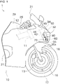
- FIG. 1 is a side view showing a front part of the motorcycle 1.
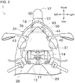
- FIG. 2 is a plan view showing the front part of the motorcycle 1.
- the motorcycle 1 has a vehicle body 10.
- This motorcycle 1 is, in other words, a two-wheeled vehicle.
- the vehicle body 10 includes a plurality of vehicle body frames that serve as the framework of the motorcycle 1.
- the motorcycle 1 has a head pipe 11 and a main frame 12 as the vehicle body frame.
- the configuration of the vehicle body frames is arbitrary and may be different from this embodiment.
- a shaft insertion hole for inserting a steering shaft which is not shown is formed in the head pipe 11.
- an upper bracket 13 is disposed above the head pipe 11.
- a lower bracket 14 is disposed below the head pipe 11.
- Fork insertion holes to which left and right front forks 15 shown in FIG. 1 are inserted are formed in the upper bracket 13 and lower bracket 14 respectively.
- a front wheel 16 is rotatably mounted on the lower part of the front forks 15.
- a front tire 17 is fixed to the front wheel 16.
- Above the front tire 17 is covered by a front fender (fender) 18.
- the main frame 12 is connected to the head pipe 11.
- the main frame 12 extends rearward from the head pipe 11.
- An engine 21 is supported on the main frame 12.
- a rear tire, which is not shown, is rotatably supported at the rear part of the main frame 12.
- the power generated by the engine 21 is transmitted to the rear tire via the drive chain which is not shown. This allows the motorcycle 1 to travel.
- the engine 21 in this embodiment is a gasoline engine.
- Other drive sources, such as an electric motor, may be provided instead of or in addition to the gasoline engine.
- a handlebar-type steering handle 28 is disposed near the upper ends of the front forks 15.
- the front forks 15 rotate, thus turning the motorcycle 1 to change the traveling direction.
- the motorcycle 1 turns, the vehicle body 10 tilts toward the center of the turn relative to the road surface. Therefore, the motorcycle 1 is a type of leaning vehicle.
- a fuel tank 29 in which fuel is stored is disposed behind the steering handle 28 and above the engine 21.
- a seat, not shown, for the driver to sit on is disposed behind the fuel tank 29. Steps, which are not shown, are disposed on the left and right sides of the vehicle body 10. The driver straddles the seat and places his/her feet on the left and right steps.
- the motorcycle 1 is a type of saddle vehicle.
- a windscreen 31 is disposed in front of the steering handle 28.
- the windscreen 31 guides the driving wind so that it is less likely to hit the driver.
- the windscreen 31 is transparent or translucent and is capable of transmitting visible light.
- a headlight 32 that illuminates the front is disposed at the front part of the vehicle body 10.
- the light source of the headlight 32 is arbitrary, and may be for example, light-emitting diode (LED), incandescent bulb, halogen bulb, or HID (High-Intensity Discharge) lamp.
- the headlight 32 is a part of the headlight device (first device) 50.
- the headlight device 50 is composed of the aforementioned light source, as well as lens, reflector, etc., not shown in the figure, as a single unit.
- the headlight device 50 is a type of lighting device. As will be described later in detail, the headlight device 50 is configured to allow the direction of the light source of the headlight 32 to be adjusted.
- One headlight 32 is disposed in the center of the vehicle width direction. However, a pair of left and right headlights may also be disposed, for example.
- a radar device (second device) 60 is provided at the front part of the vehicle body 10.
- the radar device 60 is disposed below the headlight device 50.
- the radar device 60 transmits electromagnetic waves (infrared waves, millimeter waves, or microwaves, etc.) in front of the motorcycle 1 and acquires the reflected waves (electromagnetic waves) reflected by objects. This enables detection of a direction in which the object exists and a distance to the object.
- the detection results of the radar device 60 are output to a computer (control unit, not shown) that controls the motorcycle 1. Based on the presence or absence of an object in front and the distance to the object, the computer notifies the driver of information about the object or automatically activates the brakes to assist in preventing a collision with the object.
- a cowl is disposed on the outer surface of the motorcycle 1.
- the cowl is provided for the purpose of reducing the air resistance of the motorcycle 1, protecting each component of the motorcycle 1, and improving its appearance.
- the cowl located mainly in the front surface and front part of the motorcycle 1 is referred to as front cowl 34.
- the front part of the motorcycle 1 is the portion forward of the center of the motorcycle 1 in the vehicle length direction, for example, forward of the seat.
- the front cowl 34 is shaped to project forward. Therefore, a recess is formed behind the front cowl 34.
- the external shape of the front cowl 34 includes a portion that decreases in size in the vehicle width direction and in the vertical direction as they approach the front. Therefore, an interior space of the recess of the front cowl 34 also includes a portion that decreases in size in the vehicle width direction and in the vertical direction as they approach the front.
- the headlight 32 and the radar device 60 are disposed inside the front cowl 34.
- the front of the radar device 60 is covered by the cowl, which is composed of a material that transmits electromagnetic waves of the frequencies used by radar and other devices. Therefore, the transmission and reception of the electromagnetic waves of the radar device 60 is not obstructed by the cowl.
- a partition member 35 is disposed at approximately the lower end of the interior of the front cowl 34.
- the partition member 35 is formed in the shape of a plate and its thickness direction is directed vertically.
- the partition member 35 is provided to partition the space inside the front cowl 34 and a space where the front fender 18 is disposed.
- FIG. 3 is a diagonal view from the rear showing a support frame 40.
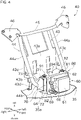
- FIG. 4 is a diagonal view from the front showing a radar stay 70 and the radar device 60.
- the head pipe 11 includes a tubular portion 11a where the shaft insertion hole is formed, and a mounting base 11b extending forward from the tubular portion 11a.
- the tubular portion 11a and the mounting base 11b are connected, for example, by welding.
- a support frame (frame) 40 is attached to the mounting base 11b.
- the support frame 40 is connected to the head pipe 11 and is located forward of the head pipe 11.
- the support frame 40 is a frame for supporting a plurality of electrical components including the headlight device 50 and the radar device 60.
- the support frame 40 includes a connection frame 41, a branch frame 42, a plate frame 43, a hanging frame 44, and a front frame 45.
- connection frame 41 is located at the connection with the mounting base 11b.
- the connection frame 41 is configured to allow insertion of the mounting base 11b.
- the connection frame 41 and the mounting base 11b are connected using fixing members such as bolts and nuts which are not shown, for example.
- the connection frame 41 and the mounting base 11b may be connected by welding.
- the branch frame 42 is fixed to the connection frame 41.
- the branch frame 42 includes two pipe-shaped members fixed to each other.
- the branch frame 42 extends diagonally forward and upward from the fixed point with the connection frame 41 and further branches in the left-right direction forming a Y-shape.
- the plate frame 43 is L-shaped in the side view. As shown in FIG. 4 , the plate frame 43 is disposed above the partition member 35. The partition member 35 is omitted in FIG. 3 , and the plate frame 43 is omitted in FIG. 5 and thereafter.
- the plate frame 43 includes a first plate 43a and a second plate 43b. The L-shape is composed of the first plate 43a and the second plate 43b.
- the first plate 43a is arranged so that its thickness direction is generally in the front-rear direction.
- the rear side of the first plate 43a is fixed to the connection frame 41 shown in FIG. 3 .
- Upper ends of the first plate 43a are fixed to the left and right branch portions of the branch frame 42, respectively.
- One or more electrical components are disposed in the space in front of the first plate 43a, respectively.
- the electrical components are, for example, the headlight device 50, an engine control unit, and a relay box.
- the headlight device 50 is omitted for the sake of drawing simplicity.
- a plurality of stays that are not shown for mounting electrical and other electrical components are fixed to the front side of the first plate 43a.
- the second plate 43b is arranged so that its thickness direction is generally vertical.
- the lower end of the first plate 43a and the rear end of the second plate 43b are connected at an approximately vertical angle.
- the front end of the second plate 43b is connected to a mounting portion 44b described later which is included in the hanging frame 44.
- Legs 43d are integrally formed at both ends of the second plate 43b in the vehicle width direction. The legs 43d extend downward from the second plate 43b and are fixed to the partition member 35.
- a third plate 43c is disposed at each of the both ends of the plate frame 43 in the vehicle width direction.
- Each of the third plates 43c is arranged so that their thickness direction is generally in the left-right direction.
- the third plate 43c is formed in a right-angled triangular shape.
- the rear end of the third plate 43c is connected to the first plate 43a at an approximately vertical angle.
- the front end of the third plate 43c is connected to an extending portion 44a described later which is included in the hanging frame 44.
- the hanging frame 44 is disposed above the partition member 35, as shown in FIG. 4 .
- the hanging frame 44 has an elongated pipe-shaped member bent into a substantially U-shape.
- the hanging frame 44 has a pair of left and right extending portions 44a, and one mounting portion 44b.
- the U-shape is composed of the extending portions 44a and the mounting portion 44b.
- the extending portion 44a extends in a straight diagonal line that is forward-descending in the side view.
- the upper end of each of the extending portions 44a is fixed to each of the branch portions of the branch frame 42.
- the mounting portion 44b extends in a straight line in the vehicle width direction.
- the mounting portion 44b connects the lower ends of the extending portions 44a.
- the hanging frame 44 is constructed by bending a single pipe, but the hanging frame 44 may be made by connecting a plurality of members by welding, fixing member, or the like.
- the front frame 45 is elongated to extend in the vehicle width direction.
- the front frame 45 connects the left and right branch portions of the branch frame 42.
- the support frame 40 has mirror stays 46 and a radar stay (stay) 70.
- the mirror stays 46 are members for mounting the left and right side mirrors. Each of the mirror stays 46 is connected to both the branch frame 42 and the front frame 45.
- the radar stay 70 is a member for mounting the radar device 60 and is connected to the mounting portion 44b of the hanging frame 44.
- the radar stay 70 will be described later in detail.
- stays and other components may be provided to the hanging frame 44 for attaching other electrical component or the like.
- the radar stay 70 is fixed to the hanging frame 44.
- the support frame 40 can support the radar device 60 via a radar bracket 80 described later.
- the radar stay 70 as shown in FIG. 4 and FIG. 5 , includes a first mounting portion 71, a second mounting portion 72, and a side plate portion 73.
- the first mounting portion 71 is a plate-shaped member and is arranged so that its thickness direction is directed vertically.
- the first mounting portion 71 is disposed at a position that is higher than the mounting portion 44b of the hanging frame 44.
- a pair of left and right attaching holes which are not shown for being inserted by screws 91, 92 to attach the radar bracket 80 are formed in the first mounting portion 71.
- the axis of each attaching hole is directed perpendicular to the first mounting portion 71, i.e., vertically.
- nuts 95 are fixed to a lower surface of the first mounting portion 71.
- female screw portions for fixing the screws 91, 92 are formed.
- the second mounting portion 72 is a plate-shaped member and is arranged so that its thickness direction is directed along the front-rear direction.
- the first mounting portion 71 is located forward of the mounting portion 44b of the hanging frame 44.
- the second mounting portion 72 is connected to the front end of the first mounting portion 71 at an approximately vertical angle.
- an attaching hole 97 for being inserted by a screw 93 to attach the radar bracket 80 is formed at an appropriate position of the second mounting portion 72.
- This attaching hole 97 is formed as an axial hole for a boss portion 96 which has a cylindrical shape fixed to the second mounting portion 72.
- the attaching hole 97 is directed perpendicular to the second mounting portion 72, i.e., in the front-rear direction.
- the boss portion 96 is disposed so that it protrudes rearward than the second mounting portion 72.
- the attaching hole 97 is formed with a female screw portion for fixing the screw 93.
- the side plate portions 73 are arranged in pairs at both ends of the radar stay 70 in the vehicle width direction. Each of the side plate portions 73 is arranged so that its thickness direction is approximately along the vehicle width direction. The rear ends of the side plate portions 73 are fixed to the front surface of the mounting portion 44b by welding or other appropriate methods. The side plate portions 73 are provided to protrude forwardly than the mounting portion 44b. This makes it easier to locate the radar device 60 forward so that the detection range of the radar device 60 is less likely to be blocked by other members. The upper end of the side plate portion 73 is fixed to the first mounting portion 71, and the front end of the side plate portion 73 is fixed to the second mounting portion 72.
- the lower side of the radar stay 70 is open.
- an insertion opening (opening) 35a is formed in a through shape. The insertion opening 35a will be described later in detail.
- the radar bracket 80 is configured as an L-shaped plate-like member, as shown in FIG. 4 and the like.
- the radar bracket 80 includes a first mounting portion 81, and a second mounting portion 82.
- the first mounting portion 81 is a plate-shaped portion and is arranged so that its thickness direction is directed vertically.
- the first mounting portion 81 is disposed above the radar stay 70.
- the first mounting portion 81 is fixed to the first mounting portion 71 included in the radar stay 70 by the screws 91, 92.
- the second mounting portion 82 is a plate-shaped portion and is arranged so that its thickness direction is directed along the front-rear direction.
- the second mounting portion 82 is disposed in front of the radar stay 70.
- the second mounting portion 82 is fixed to the second mounting portion 72 included in the radar stay 70 by the screw 93 shown in FIG. 5 .
- the radar device 60 is mounted on the front side of the second mounting portion 82.
- the three screws 91, 92, 93 are each fitted with a grommet as an anti-vibration member.
- the radar device 60 can be anti-vibration supported.
- the screws 91, 92 are mounted in the vertical direction, and the screw 93 is mounted in the front-rear direction.
- the combination of grommets arranged in a perpendicular direction to each other can suppress vibration in various directions transmitted to the radar device 60.
- the radar stay 70 can be considered the base portion of the radar device 60.
- the radar stay 70 as this base portion, is fixed to the support frame 40. Therefore, compared to the configuration in which the radar device 60 is fixed to the support frame 40 via the headlight 32 for example, or is fixed to the support frame 40 via another frame, the accumulated error with respect to the reference position of the frame can be suppressed. This allows for good mounting accuracy of the radar device 60.
- the radar device 60 includes a main body 61, a holding case 62, and an orientation adjustment mechanism (adjustment mechanism) 64.
- the main body 61 has a housing that is generally rectangular in shape.
- An antenna and circuitry for transmitting and receiving electromagnetic waves are built in the housing. This configuration allows electromagnetic waves to be transmitted and received from the front surface of the main body 61.
- a connector 66 is provided on one side of the main body 61 in the vehicle width direction. Although not shown, a power supply line to the main body 61, and a signal line to output the detection results of the main body 61 to the computer described above are connected to the connector 66.
- the holding case 62 is box-shaped with an open front.
- the main body 61 is fixed to the holding case 62 in an appropriate manner by inserting a portion of the rear side into the interior space of the holding case 62.
- the method of fixing the main body 61 to the holding case 62 may include, but is not limited to, the use of a fixing member such as a screw, for example.
- An opening is formed in the front end of the holding case 62, through which the front surface of the main body 61 is exposed.
- the orientation adjustment mechanism 64 is disposed between the holding case 62 and the radar bracket 80.
- the orientation adjustment mechanism 64 can adjust the direction of the radar device 60 (for example, a first rotation angle around a first axis in the vertical direction, and a second rotation angle around a second axis in the left-right direction).
- the orientation adjustment mechanism 64 has a pivot point part 67, a first adjustment part 68, and a second adjustment part 69.
- the pivot point part 67 is configured as a spherical bearing, for example.
- the direction of the holding case 62 with respect to the radar bracket 80 can be changed three-dimensionally around this pivot point part 67.
- Each of the first adjustment part 68 and the second adjustment part 69 is configured, for example, as a screw mechanism.
- the first adjustment part 68 and the second adjustment part 69 include adjustment members 68a, 69a which rotate integrally with screw shafts, respectively.
- the first adjustment part 68 is arranged in line with the pivot point part 67 in the vehicle width direction.
- the screw shaft of the first adjustment part 68 is directed in the front-rear direction as shown in FIG. 5 , and is rotatably supported by the second mounting portion 82 of the radar bracket 80.
- a front portion of the screw shaft is screw-coupled to the holding case 62.
- the rear portion of the screw shaft passes through a through hole in the second mounting portion 72 of the radar stay 70 and projects rearward.
- the adjustment member 68a is provided at the rear end of this screw shaft.
- the second adjustment part 69 is arranged in line with the pivot point part 67 in the vertical direction.
- the screw shaft of the second adjustment part 69 is directed in the same front-rear direction as the first adjustment part 68, and is rotatably supported by the second mounting portion 82 of the radar bracket 80.
- a front portion of the screw shaft is screw-coupled to the holding case 62.
- the rear portion of the screw shaft passes below the second mounting portion 72 of the radar stay 70 and projects rearward.
- the adjustment member 69a is provided at the rear end of this screw shaft.
- the two adjustment members 68a, 69a are located rearward of the main body 61. Therefore, the operator operates the adjustment members 68a, 69a from the rear of the radar device 60. Each of the adjustment members 68a, 69a corresponds to a second operation member.
- the radar device 60 of this embodiment is located in the center of the vehicle width direction.
- the radar device 60 is disposed so that it overlaps the headlight device 50 in plan view and is located below the headlight device 50.
- the front cowl 34 of this embodiment is shaped to decrease in size in the vehicle width direction as it approaches the front end. This may make it difficult to line up both the radar device 60 and the headlight 32, which are preferred to be located at the front end, in the vehicle width direction. In this regard, by lining up the radar device 60 and the headlight 32 vertically as in this embodiment, both can be located at the front end of the front cowl 34.
- the detection range of the radar system 60 varies depending on the content and performance of the control or the like, since the radar device 60 basically detects obstacles on the road (that is, it does not need to detect obstacles in the sky), the detection range in the left-right direction may be wider than the detection range in the up-down direction.
- the radar device 60 and the headlight 32 are arranged side by side in the vehicle width direction, if the headlight 32 is slightly further forward than the radar device 60, there is a possibility that the detection range of the radar device 60 is interfered by the headlight 32.
- a wide range of detection in the left-right direction by the radar device 60 can be realized.
- the radar bracket 80 is attached to the radar stay 70, and the radar device 60 is attached to this radar bracket 80.
- the radar device 60, the radar stay 70 and the radar bracket 80 are all located above the partition member 35.
- the radar bracket 80 and the radar device 60 do not contact with the partition member 35. Therefore, it is easier to secure a space to allow the direction of the radar device 60 to be adjusted so that the front is lower.
- the members that attach the radar bracket 80 to the radar stay 70 include the screws 91, 92. Between a pair of left and right screws 91, 92, a recess 94 with an open rear is formed in each of the first mounting portion 81 of the radar bracket 80 and the first mounting portion 71 of the radar stay 70.
- Each of the recesses 94 is located to connect between the interior space of the radar stay 70 and the space above the radar stay 70.
- the interior space of the radar stay 70 can be paraphrased as the space behind the radar device 60.
- the space above the radar stay 70 can be paraphrased as the space behind the headlight device 50.
- the headlight device 50 shown in FIG. 5 includes a housing 51 formed in the shape of a block. On the rear surface of the housing 51, a pair of left and right grommets 52, 53 are disposed side by side. The grommets 52, 53 are fixed to an appropriate member on the side of the support frame 40. A result of this, the headlight device 50 is fixed to the vehicle body 10. To attach the grommets 52, 53, cylindrical mounting bosses are formed on the housing 51 to project rearward.
- a plurality of fixing convolutions 56 are integrally formed on the housing 51.
- the fixing convolutions 56 are fixed to appropriate positions of the front cowl 34, for example.
- the headlight device 50 has an orientation adjustment mechanism (adjustment mechanism) 54.
- the orientation adjustment mechanism 54 can adjust the direction of the light source 55 of the headlight 32 (for example, a first rotation angle around a first axis in the vertical direction, and a second rotation angle around a second axis in the left-right direction).
- the orientation adjustment mechanism 54 includes a pivot point part 57, a first adjustment part 58, and a second adjustment part 59.
- the pivot point part 57 is configured as a spherical bearing, for example.
- An angle adjustment plate (not shown) is supported inside the housing 51.
- the direction of the angle adjustment plate can be changed three-dimensionally around the pivot point part 57.
- the light source 55 is fixed to the angle adjustment plate. By changing the orientation of the angle adjustment plate, the direction of the light source 55 can be changed.
- the first adjustment part 58 and second adjustment part 59 are configured as screw mechanisms.
- the first adjustment part 58 is arranged in line with the pivot point part 57 in the vehicle width direction.
- the second adjustment part 59 is arranged in line with the pivot point part 57 in the vertical direction.
- the first adjustment part 58 has a first adjustment member 58a that rotates integrally with the screw shaft.
- the second adjustment part 59 has a second adjustment member 59a that rotates integrally with the screw shaft.
- Each of the screw shafts of the first adjustment part 58 and the second adjustment part 59 is directed along the front-rear direction, and is rotatably supported by the housing. The front portion of each screw shaft is screw-coupled to the angle adjustment plate.
- the screw shaft of the first adjustment part 58 and the screw shaft of the second adjustment part 59 project rearward from the housing 51.
- a first adjustment member 58a is fixed to the rear end of the screw shaft of the first adjustment part 58.
- a second adjustment member 59a is fixed to the rear end of the screw shaft of the second adjustment part 59.
- Each of the first adjustment member 58a and the second adjustment member 59a is configured as a gear.
- the second adjustment member 59a is located on the opposite side of the first adjustment member 58a across a centerline in the width direction of the headlight device 50 (it can be rephrased as a centerline in the vehicle width direction of the motorcycle 1).
- the screw shaft can be rotated by engaging a tool with teeth formed on its tip with the first adjustment member 58a. As a result, the first rotation angle of the angle adjustment plate can be changed. Similarly, the screw shaft can be rotated by rotating the second adjustment member 59a with the teeth of the tool engaged. As a result, the second rotation angle of the angle adjustment plate can be changed.
- the first adjustment member 58a and the second adjustment member 59a are located rearward the housing 51. Therefore, the operator operates the first adjustment member 58a and the second adjustment member 59a from the rear of the headlight device 50.
- Each of the first adjustment member 58a and the second adjustment member 59a corresponds to a first operation member.
- the insertion opening 35a is formed at the partition member 35. This insertion opening 35a is used to operate the orientation adjustment mechanism 54 included in the headlight device 50 and to operate the orientation adjustment mechanism 64 included in the radar device 60.
- the insertion opening 35a is located lower than the radar device 60 and lower than the headlight device 50. On the other hand, the insertion opening 35a is located higher than the front fender 18.
- the insertion opening 35a is formed at a position between the front fender 18 and the radar stay 70.
- the insertion opening 35a faces both the radar stay 70 and the front fender 18 in the vertical direction.
- the headlight device 50 is located higher than the radar device 60. Therefore, starting from the insertion opening 35a, the headlight device 50 is farther away than the radar device 60.
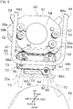
- FIG. 6 shows the operation of the orientation adjustment mechanism 64 of the radar device 60.
- the partition member 35 is omitted for ease of viewing the drawing, and only the insertion opening 35a is shown transparently with a chain line.
- the adjustment member 68a and the adjustment member 69a can be rotated as needed. This allows the orientation adjustment mechanism 64 to be operated to change the direction of the radar device 60.
- the space behind the headlight device 50 can be accessed.
- the first adjustment member 58a and the second adjustment member 59a can be rotated as needed. This allows the orientation adjustment mechanism 54 to be operated to change the direction of the light source 55 of the headlight device 50.
- the configuration can be simplified and the mechanical strength of the partition member 35 can be prevented from reduction.
- the insertion opening 35a is for orientation adjustment as described above. In addition to this, the insertion opening 35a also serves to improve the heat dissipation of internal components in the front cowl 34, such as the headlight device 50 and the radar device 60.
- the tool T1 to operate the orientation adjustment mechanism 54 of the headlight device 50 needs to be able to insert for a longer distance from the insertion opening 35a than the tool T2 to operate the orientation adjustment mechanism 64 of the radar device 60. If such a long tool T1 is attempted to be inserted perpendicular to the horizontal plane, the tool T1 will interfere with the front fender 18 which is located near below the insertion opening 35a. It is possible to form a larger insertion opening 35a, but this is often difficult from the aspect of securing space and the mechanical strength of the partition member 35.
- the first mounting portion 71 of the radar stay 70, the first mounting portion 81 of the radar bracket 80, the screws 91, 92, mounting bosses for the grommets 52, and the like are located near below the adjustment member 58a and the adjustment member 59a of the headlight device 50. If the tool T1 were to be inserted vertically, the components above would interfere with the tool T1.
- the middle portion in the vertical direction of the space where the tool T1 can be inserted is narrower in the vehicle width direction, as if it is necked.
- This necked portion is, for example, the portion corresponding to the recess 94 described above between the screws 91, 92.
- the tool T1 shown in FIG. 7 is inserted diagonally through the insertion opening 35a to operate the orientation adjustment mechanism 54. That is, for operating the adjustment member 58a located on the left side of the headlight device 50, the operator inserts the tool T1 from the right side of the front fender 18 diagonally upward to the left. For operating the adjustment member 59a located on the right side of the headlight device 50, the operator inserts the tool T1 from the left side of the front fender 18 diagonally upward to the right.
- the tip of the tool T1 can pass through the recess 94 between the screws 91, 92, and then through the side of the grommet 52 to reach the first adjustment member 58a.
- the tip of the tool T1 can pass through the recess 94 between the screws 91, 92 to reach the second adjustment member 59a.
- the top surface of the front fender 18 is curved so that the center of the vehicle width direction is convex upward. Therefore, the space between the partition member 35 and the front fender 18 is wide open on both sides in the vehicle width direction. Therefore, it is easy to insert the tool T1 diagonally upward from both the left and right sides so that it passes through the insertion opening 35a above the front fender 18.
- the headlight device 50 is configured as a single-light type.
- the headlight device 50 has become smaller, and as a result, the first adjustment member 58a and the second adjustment member 59a are often disposed near the center of the vehicle width direction.
- access to the first adjustment member 58a and the second adjustment member 59a is performed by inserting the tool T1 from the opposite side of the left and right. Therefore, the inclination angle of the tool T1 is large, thus preventing interference between the front fender 18 and the tool T1.
- FIG. 8 is a diagonal view from the front illustrating the operation of attaching the jig 100 to the motorcycle 1.
- the headlight device 50, the radar device 60, the radar bracket 80, and the like are omitted.
- the jig 100 is configured as a block-shaped member, for example, by synthetic resin.
- the jig 100 is shaped so that it can be inserted into the insertion opening 35a from below.
- a first recess 101 is formed in a front portion of the jig 100.
- This first recess 101 is formed in the shape of an elongated slit in the vehicle width direction, which is open at the top.
- the lower end of the second mounting portion 72 included in the radar stay 70 can be inserted to the first recess 101.
- the thickness of the first recess 101 is substantially equal to the thickness of the second mounting portion 72. Therefore, the jig 100 can be positioned in the front-rear direction with respect to the radar stay 70 by inserting the second mounting portion 72 into the first recess 101 as shown by the chain line in FIG. 8 . In addition, the jig 100 can be positioned vertically with respect to the radar stay 70 by a bottom of the first recess 101 contacting a lower end surface of the second mounting portion 72.
- a second recess 102 is formed in the front portion of the jig 100. This second recess 102 is formed in a U-shape with openings above and in front. A rear end of the boss portion 96 included in the radar stay 70 can be inserted into the second recess 102.
- the dimension of the second recess 102 in the vehicle width direction is substantially equal to the dimension of the boss portion 96 in the vehicle width direction. Therefore, the jig 100 can be positioned in the vehicle width direction with respect to the radar stay 70 by inserting the boss portion 96 into the second recess 102.
- the second mounting portion 72 and the boss portion 96 constitute a positioning mechanism positioning the jig 100 which has the first recess 101 and the second recess 102 at a predetermined position.
- This positioning action allows the jig 100 to be attached to the radar stay 70 at an exact position.
- the tool T1 can be guided to the exact position as shown in FIG. 7 .
- the jig 100 has two guide holes 108, 109 which are formed to penetrate diagonally.
- the two guide holes 108, 109 intersect in an X-shape.
- the shaft of the tool T1 can be inserted into each of the guide holes 108, 109.
- the first adjustment member 58a and the second adjustment member 59a is disposed left-right asymmetrically.
- the two guide holes 108, 109 formed in the jig 100 are also arranged left-right asymmetrically, specifically, the inclination angles of the guide holes 108, 109 are different from each other.
- the jig 100 has an inverted T-shape in the rear view when mounted on the radar stay 70.
- the jig 100 can be prevented from interfering with the adjustment members 68a, 69a with respect to the orientation adjustment mechanism 64 of the radar device 60, by these recesses.
- the two adjustment members 68a, 69a are located in left-right asymmetrical positions.
- the recesses formed in the jig 100 to prevent interference are also left-right asymmetrical.
- An inclined portion 105 is formed at the rear upper edge of the jig 100.
- the upper end of the jig 100 is shaped so that its dimension in the front-rear direction decreases as it moves upward.
- the gap in the height direction between the partition member 35 and the front fender 18 is small. Therefore, to attach the jig 100 to the radar stay 70, it is necessary that the jig 100 is inserted between the partition member 35 and the front fender 18 in a collapsed posture as shown in FIG. 8 , and then, as shown by the thick arrow, the jig 100 is inserted into the insertion opening 35a while simultaneously raising its posture.
- the jig 100 since the jig 100 has the inclined portion 105, the posture change of the jig 100 as described above can be easily performed. Therefore, it is easy to work with.
- guides 58b, 59b are provided in the vicinity of the first adjustment member 58a and the second adjustment member 59a, respectively. These guides 58b, 59b are configured as ribs protruding rearward from the housing 51. The guides 58b, 59b are integrally formed in the housing 51. By the guide holes 108, 109 of the jig 100 and the guides 58b, 59b of the headlight device 50, the tip of the tool T1 can be diagonally guided to the first adjustment member 58a or the second adjustment member 59a accurately.
- the motorcycle 1 includes the headlight device 50 and the radar device 60.
- the headlight device 50 includes the orientation adjustment mechanism 54.
- the radar device 60 includes the orientation adjustment mechanism 64.
- the headlight device 50 is capable of adjusting the direction of the light source 55 of the light.
- the insertion opening 35a is formed in the motorcycle 1.
- the orientation adjustment mechanism 54 included in the headlight device 50 and the orientation adjustment mechanism 64 included in the radar device 60 can be operated by being accessed from outside through the same insertion opening 35a.
- the orientation adjustment work of the headlight device 50 and the radar device 60 can be easily performed together, for example, at the time of factory shipment of the motorcycle 1.
- the motorcycle 1 of this embodiment includes the guides 58b, 59b that guide the tool T1 inserted into the insertion opening 35a to the orientation adjustment mechanism 54 included in the headlight device 50.
- the headlight device 50 and the radar device 60 are lined up in the vertical direction.
- the insertion opening 35a is disposed lower than the headlight device 50 and lower than the radar device 60.
- the insertion opening 35a is open downward.
- the direction of the headlight device 50 and the direction of the radar device can be adjusted by access from below via the insertion opening 35a, which is not easily visible from outside.
- the motorcycle 1 of this embodiment includes the support frame 40.
- the headlight device 50 is located above the radar device 60.
- the radar device 60 is attached to the support frame 40 via the radar stay 70.
- the tool T1 is inserted through the insertion opening 35a located below the headlight device 50 so that the tool T1 penetrates the radar stay 70.
- the configuration can be downsized.
- the orientation adjustment mechanism 54 included in the headlight device 50 can be operated by inserting the tool T1 diagonally up to the left or right to the insertion opening 35a.
- orientation adjustment mechanism 54 This allows the orientation adjustment mechanism 54 to be properly operated even when the middle portion of the space into which the tool T1 can be inserted is substantially necked due to the shape or arrangement of other members.
- the orientation adjustment mechanism 54 included in the headlight device 50 can adjust the direction of the light source 55 in three dimensions by adjusting the direction around the first axis in the vertical direction and adjusting the direction around the second axis in the vehicle width direction.
- the orientation adjustment mechanism 54 included in the headlight device 50 has the first adjustment member 58a and the second adjustment member 59a.
- the first adjustment member 58a is operated to change the direction of the light source 55 around the first axis.
- the second adjustment member 59a is operated to change the direction of the light source 55 around the second axis.
- the second adjustment member 59a is located opposite the first adjustment member 58a across the centerline in the width direction of the headlight device 50.
- the orientation adjustment mechanism 54 of the headlight device 50 includes the adjustment members 58a, 59a for being operated to adjust.
- the orientation adjustment mechanism 64 of the radar device 60 includes the adjustment members 68a, 69a for being operated to adjust.
- the adjustment members 58a, 59a, 68a, 69a are all located in the interior space of the front cowl 34 connected to the outside via the insertion opening 35a.
- the respective orientation adjustment mechanisms 54, 64 can be operated from the outside via the insertion opening 35a to perform the adjustment.
- the motorcycle 1 of this embodiment has a positioning mechanism for positioning the jig 100 (the second mounting portion 72 and the boss portion 96).
- the jig 100 guides the tool T1 that is inserted into the insertion opening 35a.
- the tip of the tool T1 can be guided to the exact location for operation even if the orientation adjustment mechanism 54 is far away from the insertion opening 35a, by guidance of the jig 100 that is precisely positioned.
- the tool T1 can be prevented from hitting other peripheral members such as adjustment members 68a, 69a and damaging them.
- the motorcycle 1 of this embodiment includes the headlight device 50 that can adjust the direction of the light source 55.
- the motorcycle 1 of this embodiment includes the front fender 18.
- the insertion opening 35a is located lower than the headlight device 50, is located lower than the radar device 60, and is located higher than the front fender 18. At least a portion of the insertion opening 35a faces the front fender 18 in a vertical direction.
- the following method is used to adjust the orientation of the light source 55 in the headlight device 50 and to adjust the orientation of the radar device 60. That is, the insertion opening 35a is formed in the motorcycle 1.
- the orientation adjustment mechanism 54 included in the headlight device 50 and the orientation adjustment mechanism 64 included in the radar device 60 are operated by being accessed through the same insertion opening 35a.
- the orientation adjustment work of the headlight device 50 and the radar device 60 can be easily performed together, for example, at the time of factory shipment of the motorcycle 1.
- the radar device 60 may be disposed above the headlight device 50.
- the insertion opening 35a is not limited to being located below with respect to the headlight device 50 and the radar device 60, but may be located above or to the side, for example.
- the insertion opening 35a may be formed in the cowl or in a member that is neither the partition member 35 nor the cowl.
- another device with an orientation adjustment mechanism may be disposed.
- Another device could be, for example, a camera.
- the camera can be located above or below the headlight device 50.
- the invention can be applied to a lighting device that illuminate areas other than the front of the ride.
- At least any of the orientation adjustment mechanisms in the headlight device 50 and the radar device 60 may be adjustable for direction in a plane rather than in three dimensions.
- the radar device 60 may be equipped with an adjustment mechanism that allows position adjustment instead of direction adjustment.
- the above embodiment describes an example in which the invention is applied to the motorcycle, but the invention can also be applied to other saddle vehicles.
- Other saddle vehicles include, for example, a vehicle with two front wheels and one rear wheel, a vehicle with one front wheel and two rear wheels, a vehicle with two front wheels and two rear wheels, or the like.
- Examples of four-wheeled vehicles include an all terrain vehicle for driving on a wide variety of terrain, mainly unpaved terrain.
- the present invention can also be applied to rides other than vehicles, including watercraft (PWC: Personal Water Craft) or the like for example.
Landscapes
- Engineering & Computer Science (AREA)
- Mechanical Engineering (AREA)
- Physics & Mathematics (AREA)
- Radar, Positioning & Navigation (AREA)
- Remote Sensing (AREA)
- Computer Networks & Wireless Communication (AREA)
- General Physics & Mathematics (AREA)
- General Engineering & Computer Science (AREA)
- Microelectronics & Electronic Packaging (AREA)
- Optics & Photonics (AREA)
- Electromagnetism (AREA)
- Lighting Device Outwards From Vehicle And Optical Signal (AREA)
Abstract
Description
- This invention relates to a ride in which a plurality of devices, including a lighting device, are adjustable.
- PTL 1 discloses a motorcycle including a headlight that illuminates the front and a radar device that detects the front.
- PTL 1:
Japanese Unexamined Patent Application Publication No. 2019-048554 - In the headlight such as shown in PTL 1, it is preferable to be able to adjust the direction in which the light is emitted, for example.
- The present invention is made in view of the circumstances described above, and an object of the present invention is to realize adjustment in a plurality of devices in a ride with a simple configuration.
- The problem to be solved by the present invention is as described above, and the means for solving this problem and the effect thereof are described below.
- In a first aspect of the present invention, a ride having the following configuration is provided. That is, the ride includes a first device and a second device. The first device includes an adjustment mechanism. The second device includes an adjustment mechanism. Any one of the first device and the second device is a lighting device in which a direction of a light source of light is adjustable. An opening is formed in the ride. The adjustment mechanism included in the first device and the adjustment mechanism included in the second device can be operated by being accessed from outside through the same opening.
- This simplifies the configuration and prevents a reduction in mechanical strength compared to providing separate openings for each of the first device and the second device. In addition, the adjustment work of the first device and the second device can be easily performed together, for example, at the time of factory shipment of a ride.
- In a second aspect of the present invention, the following adjustment method is provided. That is, the adjustment method targets a ride including a first device and a second device. The first device includes an adjustment mechanism. The second device includes an adjustment mechanism. Any one of the first device and the second device is a lighting device in which a direction of a light source of light is adjustable. An opening is formed in the ride. The adjustment mechanism included in the first device and the adjustment mechanism included in the second device are operated by being accessed from outside through the same opening.
- This simplifies the configuration and prevents a reduction in mechanical strength compared to providing separate openings for each of the first device and the second device. In addition, the adjustment work of the first device and the second device can be easily performed together, for example, at the time of factory shipment of a ride.
- According to the present invention, adjustment in a plurality of devices in a ride can be realized with a simple configuration.
-
-
FIG. 1 is a side view showing a front part of a motorcycle. -
FIG. 2 is a plan view showing the front part of the motorcycle. -
FIG. 3 is a diagonal view from the rear showing a support frame. -
FIG. 4 is a diagonal view from the front showing a radar stay and a radar device. -
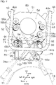
FIG. 5 is a diagonal view from the rear bottom showing an orientation adjustment mechanism of a headlight device and an orientation adjustment mechanism of the radar device. -
FIG. 6 is a diagonal view illustrating operation of the orientation adjustment mechanism of the radar device. -
FIG. 7 is a diagonal view illustrating operation of the orientation adjustment mechanism of the headlight device. -
FIG. 8 is a diagonal view from the front illustrating the operation of attaching the jig to the motorcycle. - Next, one embodiment of the invention will be described with reference to the drawings. In the following description, the front, rear, left and right of a motorcycle 1 is defined based on the direction viewed from the driver riding in the motorcycle 1 (saddle vehicle, ride). The front-rear direction corresponds to the vehicle length direction (ride length direction), and the left-right direction corresponds to the vehicle width direction (ride width direction).
- First, an overview of the motorcycle 1 according to this embodiment is described with reference to
FIG. 1 andFIG. 2 .FIG. 1 is a side view showing a front part of the motorcycle 1.FIG. 2 is a plan view showing the front part of the motorcycle 1. - As shown in
FIG. 1 , the motorcycle 1 has avehicle body 10. This motorcycle 1 is, in other words, a two-wheeled vehicle. Thevehicle body 10 includes a plurality of vehicle body frames that serve as the framework of the motorcycle 1. The motorcycle 1 has ahead pipe 11 and amain frame 12 as the vehicle body frame. The configuration of the vehicle body frames is arbitrary and may be different from this embodiment. - A shaft insertion hole for inserting a steering shaft which is not shown is formed in the
head pipe 11. As shown inFIG. 2 , anupper bracket 13 is disposed above thehead pipe 11. Alower bracket 14 is disposed below thehead pipe 11. Fork insertion holes to which left andright front forks 15 shown inFIG. 1 are inserted are formed in theupper bracket 13 andlower bracket 14 respectively. - A
front wheel 16 is rotatably mounted on the lower part of thefront forks 15. Afront tire 17 is fixed to thefront wheel 16. Above thefront tire 17 is covered by a front fender (fender) 18. - The
main frame 12 is connected to thehead pipe 11. Themain frame 12 extends rearward from thehead pipe 11. Anengine 21 is supported on themain frame 12. A rear tire, which is not shown, is rotatably supported at the rear part of themain frame 12. - The power generated by the
engine 21 is transmitted to the rear tire via the drive chain which is not shown. This allows the motorcycle 1 to travel. Theengine 21 in this embodiment is a gasoline engine. Other drive sources, such as an electric motor, may be provided instead of or in addition to the gasoline engine. - A handlebar-
type steering handle 28 is disposed near the upper ends of thefront forks 15. When the driver turns thesteering handle 28, thefront forks 15 rotate, thus turning the motorcycle 1 to change the traveling direction. In addition, when the motorcycle 1 turns, thevehicle body 10 tilts toward the center of the turn relative to the road surface. Therefore, the motorcycle 1 is a type of leaning vehicle. - A
fuel tank 29 in which fuel is stored is disposed behind the steering handle 28 and above theengine 21. A seat, not shown, for the driver to sit on is disposed behind thefuel tank 29. Steps, which are not shown, are disposed on the left and right sides of thevehicle body 10. The driver straddles the seat and places his/her feet on the left and right steps. Thus, the motorcycle 1 is a type of saddle vehicle. - A
windscreen 31 is disposed in front of thesteering handle 28. Thewindscreen 31 guides the driving wind so that it is less likely to hit the driver. To ensure the driver's visibility, thewindscreen 31 is transparent or translucent and is capable of transmitting visible light. - A
headlight 32 that illuminates the front is disposed at the front part of thevehicle body 10. The light source of theheadlight 32 is arbitrary, and may be for example, light-emitting diode (LED), incandescent bulb, halogen bulb, or HID (High-Intensity Discharge) lamp. - The
headlight 32 is a part of the headlight device (first device) 50. Theheadlight device 50 is composed of the aforementioned light source, as well as lens, reflector, etc., not shown in the figure, as a single unit. Theheadlight device 50 is a type of lighting device. As will be described later in detail, theheadlight device 50 is configured to allow the direction of the light source of theheadlight 32 to be adjusted. - One
headlight 32 is disposed in the center of the vehicle width direction. However, a pair of left and right headlights may also be disposed, for example. - A radar device (second device) 60 is provided at the front part of the
vehicle body 10. Theradar device 60 is disposed below theheadlight device 50. - The
radar device 60 transmits electromagnetic waves (infrared waves, millimeter waves, or microwaves, etc.) in front of the motorcycle 1 and acquires the reflected waves (electromagnetic waves) reflected by objects. This enables detection of a direction in which the object exists and a distance to the object. The detection results of theradar device 60 are output to a computer (control unit, not shown) that controls the motorcycle 1. Based on the presence or absence of an object in front and the distance to the object, the computer notifies the driver of information about the object or automatically activates the brakes to assist in preventing a collision with the object. - A cowl is disposed on the outer surface of the motorcycle 1. The cowl is provided for the purpose of reducing the air resistance of the motorcycle 1, protecting each component of the motorcycle 1, and improving its appearance.
- In this specification, the cowl located mainly in the front surface and front part of the motorcycle 1 is referred to as
front cowl 34. The front part of the motorcycle 1 is the portion forward of the center of the motorcycle 1 in the vehicle length direction, for example, forward of the seat. Thefront cowl 34 is shaped to project forward. Therefore, a recess is formed behind thefront cowl 34. The external shape of thefront cowl 34 includes a portion that decreases in size in the vehicle width direction and in the vertical direction as they approach the front. Therefore, an interior space of the recess of thefront cowl 34 also includes a portion that decreases in size in the vehicle width direction and in the vertical direction as they approach the front. Theheadlight 32 and theradar device 60 are disposed inside thefront cowl 34. - The front of the
radar device 60 is covered by the cowl, which is composed of a material that transmits electromagnetic waves of the frequencies used by radar and other devices. Therefore, the transmission and reception of the electromagnetic waves of theradar device 60 is not obstructed by the cowl. - A
partition member 35 is disposed at approximately the lower end of the interior of thefront cowl 34. Thepartition member 35 is formed in the shape of a plate and its thickness direction is directed vertically. Thepartition member 35 is provided to partition the space inside thefront cowl 34 and a space where thefront fender 18 is disposed. - Next, the frame structure for supporting the
radar device 60 will be described.FIG. 3 is a diagonal view from the rear showing asupport frame 40.FIG. 4 is a diagonal view from the front showing aradar stay 70 and theradar device 60. - As shown in
FIG. 3 , thehead pipe 11 includes atubular portion 11a where the shaft insertion hole is formed, and a mountingbase 11b extending forward from thetubular portion 11a. Thetubular portion 11a and the mountingbase 11b are connected, for example, by welding. - A support frame (frame) 40 is attached to the mounting
base 11b. Thesupport frame 40 is connected to thehead pipe 11 and is located forward of thehead pipe 11. Thesupport frame 40 is a frame for supporting a plurality of electrical components including theheadlight device 50 and theradar device 60. - The
support frame 40 includes aconnection frame 41, abranch frame 42, aplate frame 43, a hangingframe 44, and afront frame 45. - The
connection frame 41 is located at the connection with the mountingbase 11b. Theconnection frame 41 is configured to allow insertion of the mountingbase 11b. Theconnection frame 41 and the mountingbase 11b are connected using fixing members such as bolts and nuts which are not shown, for example. Theconnection frame 41 and the mountingbase 11b may be connected by welding. - The
branch frame 42 is fixed to theconnection frame 41. Thebranch frame 42 includes two pipe-shaped members fixed to each other. Thebranch frame 42 extends diagonally forward and upward from the fixed point with theconnection frame 41 and further branches in the left-right direction forming a Y-shape. - The
plate frame 43 is L-shaped in the side view. As shown inFIG. 4 , theplate frame 43 is disposed above thepartition member 35. Thepartition member 35 is omitted inFIG. 3 , and theplate frame 43 is omitted inFIG. 5 and thereafter. Theplate frame 43 includes afirst plate 43a and asecond plate 43b. The L-shape is composed of thefirst plate 43a and thesecond plate 43b. - The
first plate 43a is arranged so that its thickness direction is generally in the front-rear direction. The rear side of thefirst plate 43a is fixed to theconnection frame 41 shown inFIG. 3 . Upper ends of thefirst plate 43a are fixed to the left and right branch portions of thebranch frame 42, respectively. - One or more electrical components are disposed in the space in front of the
first plate 43a, respectively. The electrical components are, for example, theheadlight device 50, an engine control unit, and a relay box. InFIG. 3 andFIG. 4 , theheadlight device 50 is omitted for the sake of drawing simplicity. A plurality of stays that are not shown for mounting electrical and other electrical components are fixed to the front side of thefirst plate 43a. - The
second plate 43b is arranged so that its thickness direction is generally vertical. The lower end of thefirst plate 43a and the rear end of thesecond plate 43b are connected at an approximately vertical angle. - The front end of the
second plate 43b is connected to a mountingportion 44b described later which is included in the hangingframe 44.Legs 43d are integrally formed at both ends of thesecond plate 43b in the vehicle width direction. Thelegs 43d extend downward from thesecond plate 43b and are fixed to thepartition member 35. - A
third plate 43c is disposed at each of the both ends of theplate frame 43 in the vehicle width direction. Each of thethird plates 43c is arranged so that their thickness direction is generally in the left-right direction. Thethird plate 43c is formed in a right-angled triangular shape. The rear end of thethird plate 43c is connected to thefirst plate 43a at an approximately vertical angle. - The front end of the
third plate 43c is connected to an extendingportion 44a described later which is included in the hangingframe 44. - The hanging
frame 44 is disposed above thepartition member 35, as shown inFIG. 4 . The hangingframe 44 has an elongated pipe-shaped member bent into a substantially U-shape. The hangingframe 44 has a pair of left and right extendingportions 44a, and one mountingportion 44b. The U-shape is composed of the extendingportions 44a and the mountingportion 44b. - The extending
portion 44a extends in a straight diagonal line that is forward-descending in the side view. The upper end of each of the extendingportions 44a is fixed to each of the branch portions of thebranch frame 42. - The mounting
portion 44b extends in a straight line in the vehicle width direction. The mountingportion 44b connects the lower ends of the extendingportions 44a. - In this embodiment, the hanging
frame 44 is constructed by bending a single pipe, but the hangingframe 44 may be made by connecting a plurality of members by welding, fixing member, or the like. - The
front frame 45 is elongated to extend in the vehicle width direction. Thefront frame 45 connects the left and right branch portions of thebranch frame 42. - The
support frame 40 has mirror stays 46 and a radar stay (stay) 70. - The mirror stays 46 are members for mounting the left and right side mirrors. Each of the mirror stays 46 is connected to both the
branch frame 42 and thefront frame 45. - The radar stay 70 is a member for mounting the
radar device 60 and is connected to the mountingportion 44b of the hangingframe 44. The radar stay 70 will be described later in detail. - In addition to the above, stays and other components may be provided to the hanging
frame 44 for attaching other electrical component or the like. - Next, the
radar stay 70 will be described in detail. The radar stay 70 is fixed to the hangingframe 44. By theradar stay 70, thesupport frame 40 can support theradar device 60 via aradar bracket 80 described later. - The
radar stay 70, as shown inFIG. 4 andFIG. 5 , includes a first mountingportion 71, a second mountingportion 72, and aside plate portion 73. - The first mounting
portion 71 is a plate-shaped member and is arranged so that its thickness direction is directed vertically. The first mountingportion 71 is disposed at a position that is higher than the mountingportion 44b of the hangingframe 44. - A pair of left and right attaching holes which are not shown for being inserted by
screws radar bracket 80 are formed in the first mountingportion 71. The axis of each attaching hole is directed perpendicular to the first mountingportion 71, i.e., vertically. As shown inFIG. 5 ,nuts 95 are fixed to a lower surface of the first mountingportion 71. As a result of this, female screw portions for fixing thescrews - The second mounting
portion 72 is a plate-shaped member and is arranged so that its thickness direction is directed along the front-rear direction. The first mountingportion 71 is located forward of the mountingportion 44b of the hangingframe 44. The second mountingportion 72 is connected to the front end of the first mountingportion 71 at an approximately vertical angle. - As shown in
FIG. 5 , an attachinghole 97 for being inserted by ascrew 93 to attach theradar bracket 80 is formed at an appropriate position of the second mountingportion 72. This attachinghole 97 is formed as an axial hole for aboss portion 96 which has a cylindrical shape fixed to the second mountingportion 72. The attachinghole 97 is directed perpendicular to the second mountingportion 72, i.e., in the front-rear direction. Theboss portion 96 is disposed so that it protrudes rearward than the second mountingportion 72. The attachinghole 97 is formed with a female screw portion for fixing thescrew 93. - The
side plate portions 73 are arranged in pairs at both ends of theradar stay 70 in the vehicle width direction. Each of theside plate portions 73 is arranged so that its thickness direction is approximately along the vehicle width direction. The rear ends of theside plate portions 73 are fixed to the front surface of the mountingportion 44b by welding or other appropriate methods. Theside plate portions 73 are provided to protrude forwardly than the mountingportion 44b. This makes it easier to locate theradar device 60 forward so that the detection range of theradar device 60 is less likely to be blocked by other members. The upper end of theside plate portion 73 is fixed to the first mountingportion 71, and the front end of theside plate portion 73 is fixed to the second mountingportion 72. - The lower side of the
radar stay 70 is open. In thepartition member 35, at a position facing theradar stay 70 in the vertical direction, an insertion opening (opening) 35a is formed in a through shape. Theinsertion opening 35a will be described later in detail. - Next, the
radar bracket 80 is described in detail. - The
radar bracket 80 is configured as an L-shaped plate-like member, as shown inFIG. 4 and the like. Theradar bracket 80 includes a first mountingportion 81, and a second mountingportion 82. - The first mounting
portion 81 is a plate-shaped portion and is arranged so that its thickness direction is directed vertically. The first mountingportion 81 is disposed above theradar stay 70. The first mountingportion 81 is fixed to the first mountingportion 71 included in theradar stay 70 by thescrews - The second mounting
portion 82 is a plate-shaped portion and is arranged so that its thickness direction is directed along the front-rear direction. The second mountingportion 82 is disposed in front of theradar stay 70. The second mountingportion 82 is fixed to the second mountingportion 72 included in theradar stay 70 by thescrew 93 shown inFIG. 5 . Theradar device 60 is mounted on the front side of the second mountingportion 82. - The three
screws radar device 60 can be anti-vibration supported. Thescrews screw 93 is mounted in the front-rear direction. Thus, the combination of grommets arranged in a perpendicular direction to each other can suppress vibration in various directions transmitted to theradar device 60. - The radar stay 70 can be considered the base portion of the
radar device 60. In this embodiment, theradar stay 70, as this base portion, is fixed to thesupport frame 40. Therefore, compared to the configuration in which theradar device 60 is fixed to thesupport frame 40 via theheadlight 32 for example, or is fixed to thesupport frame 40 via another frame, the accumulated error with respect to the reference position of the frame can be suppressed. This allows for good mounting accuracy of theradar device 60. - Next, the configuration of the
radar device 60 will be described in detail. As shown inFIG. 4 and the like, theradar device 60 includes amain body 61, a holdingcase 62, and an orientation adjustment mechanism (adjustment mechanism) 64. - The
main body 61 has a housing that is generally rectangular in shape. An antenna and circuitry for transmitting and receiving electromagnetic waves are built in the housing. This configuration allows electromagnetic waves to be transmitted and received from the front surface of themain body 61. - A
connector 66 is provided on one side of themain body 61 in the vehicle width direction. Although not shown, a power supply line to themain body 61, and a signal line to output the detection results of themain body 61 to the computer described above are connected to theconnector 66. - The holding
case 62 is box-shaped with an open front. Themain body 61 is fixed to the holdingcase 62 in an appropriate manner by inserting a portion of the rear side into the interior space of the holdingcase 62. The method of fixing themain body 61 to the holdingcase 62 may include, but is not limited to, the use of a fixing member such as a screw, for example. An opening is formed in the front end of the holdingcase 62, through which the front surface of themain body 61 is exposed. - The
orientation adjustment mechanism 64 is disposed between the holdingcase 62 and theradar bracket 80. Theorientation adjustment mechanism 64 can adjust the direction of the radar device 60 (for example, a first rotation angle around a first axis in the vertical direction, and a second rotation angle around a second axis in the left-right direction). - As shown in
FIG. 5 , theorientation adjustment mechanism 64 has apivot point part 67, afirst adjustment part 68, and asecond adjustment part 69. - The
pivot point part 67 is configured as a spherical bearing, for example. The direction of the holdingcase 62 with respect to theradar bracket 80 can be changed three-dimensionally around thispivot point part 67. - Each of the
first adjustment part 68 and thesecond adjustment part 69 is configured, for example, as a screw mechanism. Thefirst adjustment part 68 and thesecond adjustment part 69 includeadjustment members - The
first adjustment part 68 is arranged in line with thepivot point part 67 in the vehicle width direction. The screw shaft of thefirst adjustment part 68 is directed in the front-rear direction as shown inFIG. 5 , and is rotatably supported by the second mountingportion 82 of theradar bracket 80. A front portion of the screw shaft is screw-coupled to the holdingcase 62. The rear portion of the screw shaft passes through a through hole in the second mountingportion 72 of theradar stay 70 and projects rearward. Theadjustment member 68a is provided at the rear end of this screw shaft. By rotating theadjustment member 68a, the holdingcase 62 can be screw fed. As a result, the first rotation angle of theradar device 60 can be adjusted. - The
second adjustment part 69 is arranged in line with thepivot point part 67 in the vertical direction. The screw shaft of thesecond adjustment part 69 is directed in the same front-rear direction as thefirst adjustment part 68, and is rotatably supported by the second mountingportion 82 of theradar bracket 80. A front portion of the screw shaft is screw-coupled to the holdingcase 62. The rear portion of the screw shaft passes below the second mountingportion 72 of theradar stay 70 and projects rearward. Theadjustment member 69a is provided at the rear end of this screw shaft. By rotating theadjustment member 69a, the holdingcase 62 can be screw fed. As a result, the second rotation angle of theradar device 60 can be adjusted. - The two
adjustment members main body 61. Therefore, the operator operates theadjustment members radar device 60. Each of theadjustment members - As shown in
FIG. 1 andFIG. 2 , theradar device 60 of this embodiment is located in the center of the vehicle width direction. Theradar device 60 is disposed so that it overlaps theheadlight device 50 in plan view and is located below theheadlight device 50. - The
front cowl 34 of this embodiment is shaped to decrease in size in the vehicle width direction as it approaches the front end. This may make it difficult to line up both theradar device 60 and theheadlight 32, which are preferred to be located at the front end, in the vehicle width direction. In this regard, by lining up theradar device 60 and theheadlight 32 vertically as in this embodiment, both can be located at the front end of thefront cowl 34. - Although the detection range of the
radar system 60 varies depending on the content and performance of the control or the like, since theradar device 60 basically detects obstacles on the road (that is, it does not need to detect obstacles in the sky), the detection range in the left-right direction may be wider than the detection range in the up-down direction. In this case, assuming that theradar device 60 and theheadlight 32 are arranged side by side in the vehicle width direction, if theheadlight 32 is slightly further forward than theradar device 60, there is a possibility that the detection range of theradar device 60 is interfered by theheadlight 32. In this regard, by lining up theradar device 60 and theheadlight 32 in the vertical direction, a wide range of detection in the left-right direction by theradar device 60 can be realized. - Next, the relationship between the
radar device 60, theradar stay 70, and theradar bracket 80 will be described. As mentioned above, theradar bracket 80 is attached to theradar stay 70, and theradar device 60 is attached to thisradar bracket 80. - As shown in
FIG. 4 , theradar device 60, theradar stay 70 and theradar bracket 80 are all located above thepartition member 35. In the situation where theradar device 60 is attached to theradar stay 70 using theradar bracket 80, theradar bracket 80 and theradar device 60 do not contact with thepartition member 35. Therefore, it is easier to secure a space to allow the direction of theradar device 60 to be adjusted so that the front is lower. - The members that attach the
radar bracket 80 to theradar stay 70 include thescrews right screws recess 94 with an open rear is formed in each of the first mountingportion 81 of theradar bracket 80 and the first mountingportion 71 of theradar stay 70. - Each of the
recesses 94 is located to connect between the interior space of theradar stay 70 and the space above theradar stay 70. The interior space of theradar stay 70 can be paraphrased as the space behind theradar device 60. The space above theradar stay 70 can be paraphrased as the space behind theheadlight device 50. - Next, the
headlight device 50 withheadlight 32 will be described. - The
headlight device 50 shown inFIG. 5 includes ahousing 51 formed in the shape of a block. On the rear surface of thehousing 51, a pair of left andright grommets grommets support frame 40. A result of this, theheadlight device 50 is fixed to thevehicle body 10. To attach thegrommets housing 51 to project rearward. - A plurality of fixing
convolutions 56 are integrally formed on thehousing 51. The fixingconvolutions 56 are fixed to appropriate positions of thefront cowl 34, for example. - The
headlight device 50 has an orientation adjustment mechanism (adjustment mechanism) 54. Theorientation adjustment mechanism 54 can adjust the direction of thelight source 55 of the headlight 32 (for example, a first rotation angle around a first axis in the vertical direction, and a second rotation angle around a second axis in the left-right direction). - The configuration of the
orientation adjustment mechanism 54 is substantially the same as that of theorientation adjustment mechanism 64 of theradar device 60, so it will be briefly described. As shown inFIG. 5 , theorientation adjustment mechanism 54 includes apivot point part 57, afirst adjustment part 58, and asecond adjustment part 59. - The
pivot point part 57 is configured as a spherical bearing, for example. An angle adjustment plate (not shown) is supported inside thehousing 51. The direction of the angle adjustment plate can be changed three-dimensionally around thepivot point part 57. Thelight source 55 is fixed to the angle adjustment plate. By changing the orientation of the angle adjustment plate, the direction of thelight source 55 can be changed. - The
first adjustment part 58 andsecond adjustment part 59 are configured as screw mechanisms. Thefirst adjustment part 58 is arranged in line with thepivot point part 57 in the vehicle width direction. Thesecond adjustment part 59 is arranged in line with thepivot point part 57 in the vertical direction. - The
first adjustment part 58 has afirst adjustment member 58a that rotates integrally with the screw shaft. Thesecond adjustment part 59 has asecond adjustment member 59a that rotates integrally with the screw shaft. Each of the screw shafts of thefirst adjustment part 58 and thesecond adjustment part 59 is directed along the front-rear direction, and is rotatably supported by the housing. The front portion of each screw shaft is screw-coupled to the angle adjustment plate. - The screw shaft of the
first adjustment part 58 and the screw shaft of thesecond adjustment part 59 project rearward from thehousing 51. Afirst adjustment member 58a is fixed to the rear end of the screw shaft of thefirst adjustment part 58. Asecond adjustment member 59a is fixed to the rear end of the screw shaft of thesecond adjustment part 59. - Each of the
first adjustment member 58a and thesecond adjustment member 59a is configured as a gear. Thesecond adjustment member 59a is located on the opposite side of thefirst adjustment member 58a across a centerline in the width direction of the headlight device 50 (it can be rephrased as a centerline in the vehicle width direction of the motorcycle 1). - The screw shaft can be rotated by engaging a tool with teeth formed on its tip with the
first adjustment member 58a. As a result, the first rotation angle of the angle adjustment plate can be changed. Similarly, the screw shaft can be rotated by rotating thesecond adjustment member 59a with the teeth of the tool engaged. As a result, the second rotation angle of the angle adjustment plate can be changed. - The
first adjustment member 58a and thesecond adjustment member 59a are located rearward thehousing 51. Therefore, the operator operates thefirst adjustment member 58a and thesecond adjustment member 59a from the rear of theheadlight device 50. Each of thefirst adjustment member 58a and thesecond adjustment member 59a corresponds to a first operation member. - Next, the orientation adjustment of the
radar device 60 and thelight source 55 will be described. - As shown in
FIG. 4 , theinsertion opening 35a is formed at thepartition member 35. Thisinsertion opening 35a is used to operate theorientation adjustment mechanism 54 included in theheadlight device 50 and to operate theorientation adjustment mechanism 64 included in theradar device 60. - As shown in
FIG. 1 and the like, theinsertion opening 35a is located lower than theradar device 60 and lower than theheadlight device 50. On the other hand, theinsertion opening 35a is located higher than thefront fender 18. - The
insertion opening 35a is formed at a position between thefront fender 18 and theradar stay 70. Theinsertion opening 35a faces both theradar stay 70 and thefront fender 18 in the vertical direction. - The
headlight device 50 is located higher than theradar device 60. Therefore, starting from theinsertion opening 35a, theheadlight device 50 is farther away than theradar device 60. -
FIG. 6 shows the operation of theorientation adjustment mechanism 64 of theradar device 60. InFIG. 6 and after, thepartition member 35 is omitted for ease of viewing the drawing, and only theinsertion opening 35a is shown transparently with a chain line. - As shown in
FIG. 6 , by inserting the tool T2 from bottom to top through theinsertion opening 35a, the space behind the second mountingportion 72 of theradar bracket 80 or the space behind the second mountingportion 82 of theradar bracket 80 can be accessed. As a result, theadjustment member 68a and theadjustment member 69a can be rotated as needed. This allows theorientation adjustment mechanism 64 to be operated to change the direction of theradar device 60. - As shown in
FIG. 7 , by inserting the tool T1 from bottom to top through thesame insertion opening 35a as above, the space behind theheadlight device 50 can be accessed. As a result, thefirst adjustment member 58a and thesecond adjustment member 59a can be rotated as needed. This allows theorientation adjustment mechanism 54 to be operated to change the direction of thelight source 55 of theheadlight device 50. - Thus, by accessing from the outside via the
common insertion opening 35a, orientation adjustments can be made with respect to theheadlight device 50 and theradar device 60. Since theinsertion opening 35a is common to both theheadlight device 50 and theradar device 60, compared to forming individual openings corresponding to theheadlight device 50 and theradar device 60, the configuration can be simplified and the mechanical strength of thepartition member 35 can be prevented from reduction. - The
insertion opening 35a is for orientation adjustment as described above. In addition to this, theinsertion opening 35a also serves to improve the heat dissipation of internal components in thefront cowl 34, such as theheadlight device 50 and theradar device 60. - The tool T1 to operate the
orientation adjustment mechanism 54 of theheadlight device 50 needs to be able to insert for a longer distance from theinsertion opening 35a than the tool T2 to operate theorientation adjustment mechanism 64 of theradar device 60. If such a long tool T1 is attempted to be inserted perpendicular to the horizontal plane, the tool T1 will interfere with thefront fender 18 which is located near below theinsertion opening 35a. It is possible to form alarger insertion opening 35a, but this is often difficult from the aspect of securing space and the mechanical strength of thepartition member 35. - Moreover, the first mounting
portion 71 of theradar stay 70, the first mountingportion 81 of theradar bracket 80, thescrews grommets 52, and the like are located near below theadjustment member 58a and theadjustment member 59a of theheadlight device 50. If the tool T1 were to be inserted vertically, the components above would interfere with the tool T1. - In other words, the middle portion in the vertical direction of the space where the tool T1 can be inserted, is narrower in the vehicle width direction, as if it is necked. This necked portion is, for example, the portion corresponding to the
recess 94 described above between thescrews - Therefore, in this embodiment, the tool T1 shown in
FIG. 7 is inserted diagonally through theinsertion opening 35a to operate theorientation adjustment mechanism 54. That is, for operating theadjustment member 58a located on the left side of theheadlight device 50, the operator inserts the tool T1 from the right side of thefront fender 18 diagonally upward to the left. For operating theadjustment member 59a located on the right side of theheadlight device 50, the operator inserts the tool T1 from the left side of thefront fender 18 diagonally upward to the right. - By inserting the tool T1 diagonally upward to the left, the tip of the tool T1 can pass through the
recess 94 between thescrews grommet 52 to reach thefirst adjustment member 58a. By inserting the tool T1 diagonally upward to the right, the tip of the tool T1 can pass through therecess 94 between thescrews second adjustment member 59a. - The top surface of the
front fender 18 is curved so that the center of the vehicle width direction is convex upward. Therefore, the space between thepartition member 35 and thefront fender 18 is wide open on both sides in the vehicle width direction. Therefore, it is easy to insert the tool T1 diagonally upward from both the left and right sides so that it passes through theinsertion opening 35a above thefront fender 18. - In this embodiment, the
headlight device 50 is configured as a single-light type. In recent years, theheadlight device 50 has become smaller, and as a result, thefirst adjustment member 58a and thesecond adjustment member 59a are often disposed near the center of the vehicle width direction. In this regard, in this embodiment, access to thefirst adjustment member 58a and thesecond adjustment member 59a is performed by inserting the tool T1 from the opposite side of the left and right. Therefore, the inclination angle of the tool T1 is large, thus preventing interference between thefront fender 18 and the tool T1. - In this embodiment, in order to guide the tool T1 diagonally to facilitate operation of the
orientation adjustment mechanism 54, ajig 100 that can be attached and detached to thevehicle body 10 is used. Thejig 100 will be described with reference toFIG. 8. FIG. 8 is a diagonal view from the front illustrating the operation of attaching thejig 100 to the motorcycle 1. InFIG. 8 , theheadlight device 50, theradar device 60, theradar bracket 80, and the like are omitted. - The
jig 100 is configured as a block-shaped member, for example, by synthetic resin. Thejig 100 is shaped so that it can be inserted into theinsertion opening 35a from below. - A
first recess 101 is formed in a front portion of thejig 100. Thisfirst recess 101 is formed in the shape of an elongated slit in the vehicle width direction, which is open at the top. The lower end of the second mountingportion 72 included in theradar stay 70 can be inserted to thefirst recess 101. - The thickness of the
first recess 101 is substantially equal to the thickness of the second mountingportion 72. Therefore, thejig 100 can be positioned in the front-rear direction with respect to theradar stay 70 by inserting the second mountingportion 72 into thefirst recess 101 as shown by the chain line inFIG. 8 . In addition, thejig 100 can be positioned vertically with respect to theradar stay 70 by a bottom of thefirst recess 101 contacting a lower end surface of the second mountingportion 72. - A
second recess 102 is formed in the front portion of thejig 100. Thissecond recess 102 is formed in a U-shape with openings above and in front. A rear end of theboss portion 96 included in theradar stay 70 can be inserted into thesecond recess 102. - The dimension of the
second recess 102 in the vehicle width direction is substantially equal to the dimension of theboss portion 96 in the vehicle width direction. Therefore, thejig 100 can be positioned in the vehicle width direction with respect to theradar stay 70 by inserting theboss portion 96 into thesecond recess 102. - The second mounting
portion 72 and theboss portion 96 constitute a positioning mechanism positioning thejig 100 which has thefirst recess 101 and thesecond recess 102 at a predetermined position. - This positioning action allows the
jig 100 to be attached to theradar stay 70 at an exact position. Thus, the tool T1 can be guided to the exact position as shown inFIG. 7 . - The
jig 100 has twoguide holes guide holes - In the
orientation adjustment mechanism 54 of theheadlight device 50, thefirst adjustment member 58a and thesecond adjustment member 59a is disposed left-right asymmetrically. Correspondingly, the twoguide holes jig 100 are also arranged left-right asymmetrically, specifically, the inclination angles of the guide holes 108, 109 are different from each other. - An appropriately shaped recess is formed at each of the upper portions of the left and right sides of the
jig 100. As a result, thejig 100 has an inverted T-shape in the rear view when mounted on theradar stay 70. Thejig 100 can be prevented from interfering with theadjustment members orientation adjustment mechanism 64 of theradar device 60, by these recesses. - In the
orientation adjustment mechanism 64 of theradar device 60, the twoadjustment members jig 100 to prevent interference are also left-right asymmetrical. - An
inclined portion 105 is formed at the rear upper edge of thejig 100. As a result, the upper end of thejig 100 is shaped so that its dimension in the front-rear direction decreases as it moves upward. In this embodiment, the gap in the height direction between thepartition member 35 and thefront fender 18 is small. Therefore, to attach thejig 100 to theradar stay 70, it is necessary that thejig 100 is inserted between thepartition member 35 and thefront fender 18 in a collapsed posture as shown inFIG. 8 , and then, as shown by the thick arrow, thejig 100 is inserted into theinsertion opening 35a while simultaneously raising its posture. In this respect, since thejig 100 has the inclinedportion 105, the posture change of thejig 100 as described above can be easily performed. Therefore, it is easy to work with. - In the
headlight device 50 shown inFIG. 7 , guides 58b, 59b are provided in the vicinity of thefirst adjustment member 58a and thesecond adjustment member 59a, respectively. Theseguides housing 51. Theguides housing 51. By the guide holes 108, 109 of thejig 100 and theguides headlight device 50, the tip of the tool T1 can be diagonally guided to thefirst adjustment member 58a or thesecond adjustment member 59a accurately. - As described above, the motorcycle 1 includes the
headlight device 50 and theradar device 60. Theheadlight device 50 includes theorientation adjustment mechanism 54. Theradar device 60 includes theorientation adjustment mechanism 64. Theheadlight device 50 is capable of adjusting the direction of thelight source 55 of the light. Theinsertion opening 35a is formed in the motorcycle 1. Theorientation adjustment mechanism 54 included in theheadlight device 50 and theorientation adjustment mechanism 64 included in theradar device 60 can be operated by being accessed from outside through thesame insertion opening 35a. - This simplifies the configuration and prevents a reduction in mechanical strength compared to providing separate openings for each of the
headlight device 50 and theradar device 60. In addition, the orientation adjustment work of theheadlight device 50 and theradar device 60 can be easily performed together, for example, at the time of factory shipment of the motorcycle 1. - The motorcycle 1 of this embodiment includes the
guides insertion opening 35a to theorientation adjustment mechanism 54 included in theheadlight device 50. - This provides good workability.
- In the motorcycle 1 of this embodiment, the
headlight device 50 and theradar device 60 are lined up in the vertical direction. Theinsertion opening 35a is disposed lower than theheadlight device 50 and lower than theradar device 60. Theinsertion opening 35a is open downward. - Thus, the direction of the
headlight device 50 and the direction of the radar device can be adjusted by access from below via theinsertion opening 35a, which is not easily visible from outside. - The motorcycle 1 of this embodiment includes the
support frame 40. Theheadlight device 50 is located above theradar device 60. Theradar device 60 is attached to thesupport frame 40 via theradar stay 70. For operating theorientation adjustment mechanism 54 included in theheadlight device 50, the tool T1 is inserted through theinsertion opening 35a located below theheadlight device 50 so that the tool T1 penetrates theradar stay 70. - This allows a path for inserting the tool T1 to be secured inside the
radar stay 70. Thus, the configuration can be downsized. - In the motorcycle 1 of this embodiment, the
orientation adjustment mechanism 54 included in theheadlight device 50 can be operated by inserting the tool T1 diagonally up to the left or right to theinsertion opening 35a. - This allows the
orientation adjustment mechanism 54 to be properly operated even when the middle portion of the space into which the tool T1 can be inserted is substantially necked due to the shape or arrangement of other members. - In the motorcycle 1 of this embodiment, the
orientation adjustment mechanism 54 included in theheadlight device 50 can adjust the direction of thelight source 55 in three dimensions by adjusting the direction around the first axis in the vertical direction and adjusting the direction around the second axis in the vehicle width direction. - This allows for good adjustment of the direction of the
light source 55. - In the motorcycle 1 of this embodiment, the
orientation adjustment mechanism 54 included in theheadlight device 50 has thefirst adjustment member 58a and thesecond adjustment member 59a. Thefirst adjustment member 58a is operated to change the direction of thelight source 55 around the first axis. Thesecond adjustment member 59a is operated to change the direction of thelight source 55 around the second axis. Thesecond adjustment member 59a is located opposite thefirst adjustment member 58a across the centerline in the width direction of theheadlight device 50. - This allows for a simplified structure.
- In the motorcycle 1 of this embodiment, the
orientation adjustment mechanism 54 of theheadlight device 50 includes theadjustment members orientation adjustment mechanism 64 of theradar device 60 includes theadjustment members adjustment members front cowl 34 connected to the outside via theinsertion opening 35a. - Therefore, the respective
orientation adjustment mechanisms insertion opening 35a to perform the adjustment. - The motorcycle 1 of this embodiment has a positioning mechanism for positioning the jig 100 (the second mounting
portion 72 and the boss portion 96). Thejig 100 guides the tool T1 that is inserted into theinsertion opening 35a. - This allows the tip of the tool T1 to be guided to the exact location for operation even if the
orientation adjustment mechanism 54 is far away from theinsertion opening 35a, by guidance of thejig 100 that is precisely positioned. In addition, the tool T1 can be prevented from hitting other peripheral members such asadjustment members - The motorcycle 1 of this embodiment includes the
headlight device 50 that can adjust the direction of thelight source 55. - This allows the orientation adjustment of the
headlight device 50 to be achieved with a simple configuration. - The motorcycle 1 of this embodiment includes the
front fender 18. Theinsertion opening 35a is located lower than theheadlight device 50, is located lower than theradar device 60, and is located higher than thefront fender 18. At least a portion of theinsertion opening 35a faces thefront fender 18 in a vertical direction. - This allows the orientation adjustment of the
headlight device 50 by effectively utilizing the space near thefront fender 18. - In this embodiment, the following method is used to adjust the orientation of the
light source 55 in theheadlight device 50 and to adjust the orientation of theradar device 60. That is, theinsertion opening 35a is formed in the motorcycle 1. Theorientation adjustment mechanism 54 included in theheadlight device 50 and theorientation adjustment mechanism 64 included in theradar device 60 are operated by being accessed through thesame insertion opening 35a. - This simplifies the configuration and prevents a reduction in mechanical strength compared to providing separate openings for each of the
headlight device 50 and theradar device 60. In addition, the orientation adjustment work of theheadlight device 50 and theradar device 60 can be easily performed together, for example, at the time of factory shipment of the motorcycle 1. - Although the preferred embodiment and the modifications of the present invention have been described above, the configurations described above may be modified as follows, for example.
- The
radar device 60 may be disposed above theheadlight device 50. - The
insertion opening 35a is not limited to being located below with respect to theheadlight device 50 and theradar device 60, but may be located above or to the side, for example. Theinsertion opening 35a may be formed in the cowl or in a member that is neither thepartition member 35 nor the cowl. - Instead of or in addition to the
radar device 60, another device with an orientation adjustment mechanism may be disposed. Another device could be, for example, a camera. The camera can be located above or below theheadlight device 50. - Instead of the
headlight device 50, the invention can be applied to a lighting device that illuminate areas other than the front of the ride. - At least any of the orientation adjustment mechanisms in the
headlight device 50 and theradar device 60 may be adjustable for direction in a plane rather than in three dimensions. - For example, the
radar device 60 may be equipped with an adjustment mechanism that allows position adjustment instead of direction adjustment. - The above embodiment describes an example in which the invention is applied to the motorcycle, but the invention can also be applied to other saddle vehicles. Other saddle vehicles include, for example, a vehicle with two front wheels and one rear wheel, a vehicle with one front wheel and two rear wheels, a vehicle with two front wheels and two rear wheels, or the like. Examples of four-wheeled vehicles include an all terrain vehicle for driving on a wide variety of terrain, mainly unpaved terrain. Furthermore, the present invention can also be applied to rides other than vehicles, including watercraft (PWC: Personal Water Craft) or the like for example.
Claims (12)
- A ride (1) comprising:a first device (50) that includes an adjustment mechanism (54); anda second device (60) that includes an adjustment mechanism (64), whereinany one of the first device (50) and the second device (60) is a lighting device (50) in which a direction of a light source (55) of light is adjustable,an opening (35a) is formed, andthe adjustment mechanism (54) included in the first device (50) and the adjustment mechanism (64) included in the second device (60) can be operated by being accessed from outside through the same opening (35a).
- A ride (1) according to claim 1, wherein
the ride (1) includes a guide (58b, 59b) that guides a tool (T1) inserted into the opening (35a) to the adjustment mechanism (54) included in the first device (50). - A ride (1) according to claim 1 or 2, whereinthe first device (50) and the second device (60) are lined up in a vertical direction,the opening (35a) is disposed lower than the first device (50) and lower than the second device (60), andthe opening (35a) is open downward.
- A ride (1) according to claim 3, comprising:a frame (40); whereinthe first device (50) is located above the second device (60),the second device (60) is attached to the frame (40) via a stay (70), andfor operating the adjustment mechanism (54) included in the first device (50), a tool (T1) is inserted through the opening (35a) located below the first device (50) so that the tool (T1) penetrates the stay (70).
- A ride (1) according to claim 3 or 4, wherein
the adjustment mechanism (54) included in the first device (50) can be operated by inserting a tool (T1) diagonally up to right or diagonally up to left with respect to the opening (35a). - The ride (1) according to any one of claims 1 to 5, wherein
the adjustment mechanism (54) included in the first device (50) is an orientation adjustment mechanism (54) which can adjust a direction in three dimensions by adjusting the direction around a first axis in a vertical direction and adjusting the direction around a second axis in a ride width direction. - The ride (1) according to claim 6, wherein
the orientation adjustment mechanism (54) of the first device (50) includes:a first adjustment member (58a) operated to change the direction around the first axis; anda second adjustment member (59a) operated to change the direction around the second axis, andthe second adjustment member (59a) is located opposite the first adjustment member (58a) across a centerline in a width direction of the first device (50). - The ride (1) according to any one of claims 1 to 7, whereinthe adjustment mechanism (54) of the first device (50) has a first operation member (58a, 59a) for being operated to adjust,the adjustment mechanism (64) of the second device (60) has a second operation member (68a, 69a) for being operated to adjust, andthe first operation member (58a, 59a) and second operation member (68a, 69a) are located at an interior space connected to the outside via the opening (35a).
- The ride (1) according to any one of claims 1 to 8, comprising:
a positioning mechanism (72, 96) for positioning a jig (100) that guides a tool (T1) inserted into the opening (35a). - A saddle vehicle (1) as the ride according to any one of claims 1 to 9, wherein the first device (50) is a headlight device (50).
- The saddle vehicle (1) according to claim 10 comprising:a fender (18); whereinthe opening (35a) is located lower than the first device (50), is located lower than the second device (60), and is located higher than the fender (18), andat least a portion of the opening (35a) faces the fender (18) in a vertical direction.
- An adjustment method in a ride (1) comprising:a first device (50) that includes an adjustment mechanism (54); anda second device (60) that includes an adjustment mechanism (64), whereinany one of the first device (50) and the second device (60) is a lighting device (50) in which a direction of a light source (55) of light is adjustable,an opening (35a) is formed in the ride (1), andthe adjustment mechanism (54) included in the first device (50) and the adjustment mechanism (64) included in the second device (60) are operated by being accessed from outside through the same opening (35a).
Applications Claiming Priority (1)
| Application Number | Priority Date | Filing Date | Title |
|---|---|---|---|
| JP2021067411A JP7569259B2 (en) | 2021-04-12 | 2021-04-12 | Vehicle, saddle-type vehicle, and adjustment method |
Publications (2)
| Publication Number | Publication Date |
|---|---|
| EP4074584A1 true EP4074584A1 (en) | 2022-10-19 |
| EP4074584B1 EP4074584B1 (en) | 2025-07-23 |
Family
ID=81386635
Family Applications (1)
| Application Number | Title | Priority Date | Filing Date |
|---|---|---|---|
| EP22167658.8A Active EP4074584B1 (en) | 2021-04-12 | 2022-04-11 | Saddle vehicle and adjustment method |
Country Status (3)
| Country | Link |
|---|---|
| US (1) | US11932341B2 (en) |
| EP (1) | EP4074584B1 (en) |
| JP (1) | JP7569259B2 (en) |
Families Citing this family (2)
| Publication number | Priority date | Publication date | Assignee | Title |
|---|---|---|---|---|
| JP7645162B2 (en) * | 2021-10-08 | 2025-03-13 | カワサキモータース株式会社 | LIDAR calibration method |
| JP2025002931A (en) * | 2023-06-23 | 2025-01-09 | スズキ株式会社 | Vehicle front structure |
Citations (5)
| Publication number | Priority date | Publication date | Assignee | Title |
|---|---|---|---|---|
| JP2001158390A (en) * | 1999-11-30 | 2001-06-12 | Yamaha Motor Co Ltd | Vehicle-to-vehicle communication device for straddle-type vehicles |
| EP3176034A1 (en) * | 2015-12-04 | 2017-06-07 | Automotive Lighting Italia S.p.A. | Adjustable lighting device for vehicles |
| US20180162265A1 (en) * | 2016-12-08 | 2018-06-14 | Kawasaki Jukogyo Kabushiki Kaisha | Straddle-type vehicle |
| JP2019048554A (en) | 2017-09-11 | 2019-03-28 | 川崎重工業株式会社 | Motorcycle |
| CN208687627U (en) * | 2018-07-26 | 2019-04-02 | 力帆实业(集团)股份有限公司 | Structure for easy adjustment of headlamp light and a motorcycle |
Family Cites Families (9)
| Publication number | Priority date | Publication date | Assignee | Title |
|---|---|---|---|---|
| JPH0615832B2 (en) | 1984-08-03 | 1994-03-02 | 日産自動車株式会社 | Air-fuel ratio controller |
| JP3007260B2 (en) * | 1994-04-27 | 2000-02-07 | 株式会社小糸製作所 | Automotive headlamp |
| JP3376839B2 (en) * | 1996-11-20 | 2003-02-10 | スズキ株式会社 | Headlamp optical axis adjustment device for motorcycle with cowling |
| JP4375897B2 (en) * | 2000-11-24 | 2009-12-02 | スタンレー電気株式会社 | Protective structure of aiming operation part in vehicular lamp |
| JP2004231115A (en) * | 2003-01-31 | 2004-08-19 | Toyota Motor Corp | Inverter vehicle bracket |
| JP5953982B2 (en) * | 2012-06-28 | 2016-07-20 | 市光工業株式会社 | Vehicle lighting |
| ES2546200B1 (en) | 2014-03-20 | 2016-03-23 | Nad, S. L.. | Clamping device for side cases to the chassis of motorcycles and similar vehicles |
| JP6490728B2 (en) * | 2017-03-15 | 2019-03-27 | 本田技研工業株式会社 | Headlight structure of saddle-ride type vehicle |
| JP7267077B2 (en) * | 2019-04-12 | 2023-05-01 | 株式会社小糸製作所 | vehicle lamp |
-
2021
- 2021-04-12 JP JP2021067411A patent/JP7569259B2/en active Active
-
2022
- 2022-04-11 US US17/658,756 patent/US11932341B2/en active Active
- 2022-04-11 EP EP22167658.8A patent/EP4074584B1/en active Active
Patent Citations (5)
| Publication number | Priority date | Publication date | Assignee | Title |
|---|---|---|---|---|
| JP2001158390A (en) * | 1999-11-30 | 2001-06-12 | Yamaha Motor Co Ltd | Vehicle-to-vehicle communication device for straddle-type vehicles |
| EP3176034A1 (en) * | 2015-12-04 | 2017-06-07 | Automotive Lighting Italia S.p.A. | Adjustable lighting device for vehicles |
| US20180162265A1 (en) * | 2016-12-08 | 2018-06-14 | Kawasaki Jukogyo Kabushiki Kaisha | Straddle-type vehicle |
| JP2019048554A (en) | 2017-09-11 | 2019-03-28 | 川崎重工業株式会社 | Motorcycle |
| CN208687627U (en) * | 2018-07-26 | 2019-04-02 | 力帆实业(集团)股份有限公司 | Structure for easy adjustment of headlamp light and a motorcycle |
Also Published As
| Publication number | Publication date |
|---|---|
| US20220324528A1 (en) | 2022-10-13 |
| EP4074584B1 (en) | 2025-07-23 |
| JP7569259B2 (en) | 2024-10-17 |
| US11932341B2 (en) | 2024-03-19 |
| JP2022162491A (en) | 2022-10-24 |
Similar Documents
| Publication | Publication Date | Title |
|---|---|---|
| US11548589B2 (en) | Motorcycle | |
| JP7017686B2 (en) | Motorcycle | |
| EP3838728B1 (en) | Straddle vehicle | |
| CN112188979B (en) | straddle vehicle | |
| JP5525639B1 (en) | Light unit for vehicles that turn in a lean position and vehicles that turn in a lean position | |
| EP4074584B1 (en) | Saddle vehicle and adjustment method | |
| JP2017039487A (en) | Lean vehicle | |
| CN107406113B (en) | Lighting device structure comprising auxiliary lighting | |
| BRPI0803356B1 (en) | headlight device for motorcycle and vehicle supplied with it | |
| US9487258B2 (en) | Straddled vehicle | |
| JP6975844B2 (en) | Cornering lights for saddle-mounted vehicles | |
| JP2017202712A (en) | Headlamp device for vehicles | |
| US10293741B2 (en) | Straddle-type vehicle | |
| EP3560805B1 (en) | Straddled vehicle | |
| US11763680B2 (en) | Straddled vehicle | |
| JP6975843B2 (en) | Cornering lights for saddle-mounted vehicles | |
| JP2018094946A (en) | Saddle-riding type vehicle | |
| BR112021011233A2 (en) | Mounting Vehicle Lighting Device | |
| EP1780104B1 (en) | Winker mounting structure | |
| JP2021030797A (en) | Scooter type vehicle | |
| US20240375738A1 (en) | Saddle-riding vehicle and headlamp unit | |
| CN121043978A (en) | riding vehicles | |
| JP2021172163A (en) | Saddle-type vehicle |
Legal Events
| Date | Code | Title | Description |
|---|---|---|---|
| PUAI | Public reference made under article 153(3) epc to a published international application that has entered the european phase |
Free format text: ORIGINAL CODE: 0009012 |
|
| STAA | Information on the status of an ep patent application or granted ep patent |
Free format text: STATUS: REQUEST FOR EXAMINATION WAS MADE |
|
| 17P | Request for examination filed |
Effective date: 20220411 |
|
| AK | Designated contracting states |
Kind code of ref document: A1 Designated state(s): AL AT BE BG CH CY CZ DE DK EE ES FI FR GB GR HR HU IE IS IT LI LT LU LV MC MK MT NL NO PL PT RO RS SE SI SK SM TR |
|
| RBV | Designated contracting states (corrected) |
Designated state(s): AL AT BE BG CH CY CZ DE DK EE ES FI FR GB GR HR HU IE IS IT LI LT LU LV MC MK MT NL NO PL PT RO RS SE SI SK SM TR |
|
| STAA | Information on the status of an ep patent application or granted ep patent |
Free format text: STATUS: EXAMINATION IS IN PROGRESS |
|
| 17Q | First examination report despatched |
Effective date: 20230728 |
|
| GRAP | Despatch of communication of intention to grant a patent |
Free format text: ORIGINAL CODE: EPIDOSNIGR1 |
|
| STAA | Information on the status of an ep patent application or granted ep patent |
Free format text: STATUS: GRANT OF PATENT IS INTENDED |
|
| RIC1 | Information provided on ipc code assigned before grant |
Ipc: G01S 7/40 20060101ALN20250321BHEP Ipc: G01S 13/931 20200101ALI20250321BHEP Ipc: G01S 7/02 20060101ALI20250321BHEP Ipc: B60Q 1/068 20060101ALI20250321BHEP Ipc: B62J 45/41 20200101ALI20250321BHEP Ipc: B62J 45/42 20200101ALI20250321BHEP Ipc: B62J 6/027 20200101ALI20250321BHEP Ipc: B62J 6/025 20200101AFI20250321BHEP |
|
| INTG | Intention to grant announced |
Effective date: 20250423 |
|
| GRAS | Grant fee paid |
Free format text: ORIGINAL CODE: EPIDOSNIGR3 |
|
| GRAA | (expected) grant |
Free format text: ORIGINAL CODE: 0009210 |
|
| STAA | Information on the status of an ep patent application or granted ep patent |
Free format text: STATUS: THE PATENT HAS BEEN GRANTED |
|
| AK | Designated contracting states |
Kind code of ref document: B1 Designated state(s): AL AT BE BG CH CY CZ DE DK EE ES FI FR GB GR HR HU IE IS IT LI LT LU LV MC MK MT NL NO PL PT RO RS SE SI SK SM TR |
|
| REG | Reference to a national code |
Ref country code: GB Ref legal event code: FG4D |
|
| REG | Reference to a national code |
Ref country code: CH Ref legal event code: EP |
|
| REG | Reference to a national code |
Ref country code: DE Ref legal event code: R096 Ref document number: 602022017899 Country of ref document: DE |
|
| REG | Reference to a national code |
Ref country code: IE Ref legal event code: FG4D |
|
| REG | Reference to a national code |
Ref country code: NL Ref legal event code: MP Effective date: 20250723 |
|
| PG25 | Lapsed in a contracting state [announced via postgrant information from national office to epo] |
Ref country code: PT Free format text: LAPSE BECAUSE OF FAILURE TO SUBMIT A TRANSLATION OF THE DESCRIPTION OR TO PAY THE FEE WITHIN THE PRESCRIBED TIME-LIMIT Effective date: 20251124 |
|
| PG25 | Lapsed in a contracting state [announced via postgrant information from national office to epo] |
Ref country code: NL Free format text: LAPSE BECAUSE OF FAILURE TO SUBMIT A TRANSLATION OF THE DESCRIPTION OR TO PAY THE FEE WITHIN THE PRESCRIBED TIME-LIMIT Effective date: 20250723 |
|
| REG | Reference to a national code |
Ref country code: AT Ref legal event code: MK05 Ref document number: 1816173 Country of ref document: AT Kind code of ref document: T Effective date: 20250723 |
|
| PG25 | Lapsed in a contracting state [announced via postgrant information from national office to epo] |
Ref country code: IS Free format text: LAPSE BECAUSE OF FAILURE TO SUBMIT A TRANSLATION OF THE DESCRIPTION OR TO PAY THE FEE WITHIN THE PRESCRIBED TIME-LIMIT Effective date: 20251123 |
|
| PG25 | Lapsed in a contracting state [announced via postgrant information from national office to epo] |
Ref country code: NO Free format text: LAPSE BECAUSE OF FAILURE TO SUBMIT A TRANSLATION OF THE DESCRIPTION OR TO PAY THE FEE WITHIN THE PRESCRIBED TIME-LIMIT Effective date: 20251023 |
|
| REG | Reference to a national code |
Ref country code: LT Ref legal event code: MG9D |
|
| PG25 | Lapsed in a contracting state [announced via postgrant information from national office to epo] |
Ref country code: AT Free format text: LAPSE BECAUSE OF FAILURE TO SUBMIT A TRANSLATION OF THE DESCRIPTION OR TO PAY THE FEE WITHIN THE PRESCRIBED TIME-LIMIT Effective date: 20250723 |
|
| PG25 | Lapsed in a contracting state [announced via postgrant information from national office to epo] |
Ref country code: FI Free format text: LAPSE BECAUSE OF FAILURE TO SUBMIT A TRANSLATION OF THE DESCRIPTION OR TO PAY THE FEE WITHIN THE PRESCRIBED TIME-LIMIT Effective date: 20250723 |
|
| PG25 | Lapsed in a contracting state [announced via postgrant information from national office to epo] |
Ref country code: HR Free format text: LAPSE BECAUSE OF FAILURE TO SUBMIT A TRANSLATION OF THE DESCRIPTION OR TO PAY THE FEE WITHIN THE PRESCRIBED TIME-LIMIT Effective date: 20250723 |
|
| PG25 | Lapsed in a contracting state [announced via postgrant information from national office to epo] |
Ref country code: GR Free format text: LAPSE BECAUSE OF FAILURE TO SUBMIT A TRANSLATION OF THE DESCRIPTION OR TO PAY THE FEE WITHIN THE PRESCRIBED TIME-LIMIT Effective date: 20251024 |
|
| PG25 | Lapsed in a contracting state [announced via postgrant information from national office to epo] |
Ref country code: SE Free format text: LAPSE BECAUSE OF FAILURE TO SUBMIT A TRANSLATION OF THE DESCRIPTION OR TO PAY THE FEE WITHIN THE PRESCRIBED TIME-LIMIT Effective date: 20250723 |
|
| PG25 | Lapsed in a contracting state [announced via postgrant information from national office to epo] |
Ref country code: LV Free format text: LAPSE BECAUSE OF FAILURE TO SUBMIT A TRANSLATION OF THE DESCRIPTION OR TO PAY THE FEE WITHIN THE PRESCRIBED TIME-LIMIT Effective date: 20250723 |
|
| PG25 | Lapsed in a contracting state [announced via postgrant information from national office to epo] |
Ref country code: PL Free format text: LAPSE BECAUSE OF FAILURE TO SUBMIT A TRANSLATION OF THE DESCRIPTION OR TO PAY THE FEE WITHIN THE PRESCRIBED TIME-LIMIT Effective date: 20250723 Ref country code: BG Free format text: LAPSE BECAUSE OF FAILURE TO SUBMIT A TRANSLATION OF THE DESCRIPTION OR TO PAY THE FEE WITHIN THE PRESCRIBED TIME-LIMIT Effective date: 20250723 |
|
| PG25 | Lapsed in a contracting state [announced via postgrant information from national office to epo] |
Ref country code: RS Free format text: LAPSE BECAUSE OF FAILURE TO SUBMIT A TRANSLATION OF THE DESCRIPTION OR TO PAY THE FEE WITHIN THE PRESCRIBED TIME-LIMIT Effective date: 20251023 |
|
| PG25 | Lapsed in a contracting state [announced via postgrant information from national office to epo] |
Ref country code: ES Free format text: LAPSE BECAUSE OF FAILURE TO SUBMIT A TRANSLATION OF THE DESCRIPTION OR TO PAY THE FEE WITHIN THE PRESCRIBED TIME-LIMIT Effective date: 20250723 |
|
| PG25 | Lapsed in a contracting state [announced via postgrant information from national office to epo] |
Ref country code: SM Free format text: LAPSE BECAUSE OF FAILURE TO SUBMIT A TRANSLATION OF THE DESCRIPTION OR TO PAY THE FEE WITHIN THE PRESCRIBED TIME-LIMIT Effective date: 20250723 |
|
| PG25 | Lapsed in a contracting state [announced via postgrant information from national office to epo] |
Ref country code: DK Free format text: LAPSE BECAUSE OF FAILURE TO SUBMIT A TRANSLATION OF THE DESCRIPTION OR TO PAY THE FEE WITHIN THE PRESCRIBED TIME-LIMIT Effective date: 20250723 |
|
| PG25 | Lapsed in a contracting state [announced via postgrant information from national office to epo] |
Ref country code: IT Free format text: LAPSE BECAUSE OF FAILURE TO SUBMIT A TRANSLATION OF THE DESCRIPTION OR TO PAY THE FEE WITHIN THE PRESCRIBED TIME-LIMIT Effective date: 20250723 |
|
| PG25 | Lapsed in a contracting state [announced via postgrant information from national office to epo] |
Ref country code: CZ Free format text: LAPSE BECAUSE OF FAILURE TO SUBMIT A TRANSLATION OF THE DESCRIPTION OR TO PAY THE FEE WITHIN THE PRESCRIBED TIME-LIMIT Effective date: 20250723 |
|
| PG25 | Lapsed in a contracting state [announced via postgrant information from national office to epo] |
Ref country code: SK Free format text: LAPSE BECAUSE OF FAILURE TO SUBMIT A TRANSLATION OF THE DESCRIPTION OR TO PAY THE FEE WITHIN THE PRESCRIBED TIME-LIMIT Effective date: 20250723 Ref country code: EE Free format text: LAPSE BECAUSE OF FAILURE TO SUBMIT A TRANSLATION OF THE DESCRIPTION OR TO PAY THE FEE WITHIN THE PRESCRIBED TIME-LIMIT Effective date: 20250723 |