EP4074510A1 - Printing apparatus - Google Patents
Printing apparatus Download PDFInfo
- Publication number
- EP4074510A1 EP4074510A1 EP22162175.8A EP22162175A EP4074510A1 EP 4074510 A1 EP4074510 A1 EP 4074510A1 EP 22162175 A EP22162175 A EP 22162175A EP 4074510 A1 EP4074510 A1 EP 4074510A1
- Authority
- EP
- European Patent Office
- Prior art keywords
- ink
- tube
- carriage
- tube holder
- printing apparatus
- Prior art date
- Legal status (The legal status is an assumption and is not a legal conclusion. Google has not performed a legal analysis and makes no representation as to the accuracy of the status listed.)
- Granted
Links
Images

Classifications
-
- B—PERFORMING OPERATIONS; TRANSPORTING
- B41—PRINTING; LINING MACHINES; TYPEWRITERS; STAMPS
- B41J—TYPEWRITERS; SELECTIVE PRINTING MECHANISMS, i.e. MECHANISMS PRINTING OTHERWISE THAN FROM A FORME; CORRECTION OF TYPOGRAPHICAL ERRORS
- B41J2/00—Typewriters or selective printing mechanisms characterised by the printing or marking process for which they are designed
- B41J2/005—Typewriters or selective printing mechanisms characterised by the printing or marking process for which they are designed characterised by bringing liquid or particles selectively into contact with a printing material
- B41J2/01—Ink jet
- B41J2/17—Ink jet characterised by ink handling
- B41J2/175—Ink supply systems ; Circuit parts therefor
- B41J2/17503—Ink cartridges
- B41J2/1752—Mounting within the printer
- B41J2/17523—Ink connection
-
- B—PERFORMING OPERATIONS; TRANSPORTING
- B41—PRINTING; LINING MACHINES; TYPEWRITERS; STAMPS
- B41J—TYPEWRITERS; SELECTIVE PRINTING MECHANISMS, i.e. MECHANISMS PRINTING OTHERWISE THAN FROM A FORME; CORRECTION OF TYPOGRAPHICAL ERRORS
- B41J2/00—Typewriters or selective printing mechanisms characterised by the printing or marking process for which they are designed
- B41J2/005—Typewriters or selective printing mechanisms characterised by the printing or marking process for which they are designed characterised by bringing liquid or particles selectively into contact with a printing material
- B41J2/01—Ink jet
- B41J2/17—Ink jet characterised by ink handling
- B41J2/175—Ink supply systems ; Circuit parts therefor
-
- B—PERFORMING OPERATIONS; TRANSPORTING
- B41—PRINTING; LINING MACHINES; TYPEWRITERS; STAMPS
- B41J—TYPEWRITERS; SELECTIVE PRINTING MECHANISMS, i.e. MECHANISMS PRINTING OTHERWISE THAN FROM A FORME; CORRECTION OF TYPOGRAPHICAL ERRORS
- B41J2/00—Typewriters or selective printing mechanisms characterised by the printing or marking process for which they are designed
- B41J2/005—Typewriters or selective printing mechanisms characterised by the printing or marking process for which they are designed characterised by bringing liquid or particles selectively into contact with a printing material
- B41J2/01—Ink jet
- B41J2/17—Ink jet characterised by ink handling
- B41J2/175—Ink supply systems ; Circuit parts therefor
- B41J2/17503—Ink cartridges
- B41J2/17506—Refilling of the cartridge
- B41J2/17509—Whilst mounted in the printer
-
- B—PERFORMING OPERATIONS; TRANSPORTING
- B41—PRINTING; LINING MACHINES; TYPEWRITERS; STAMPS
- B41J—TYPEWRITERS; SELECTIVE PRINTING MECHANISMS, i.e. MECHANISMS PRINTING OTHERWISE THAN FROM A FORME; CORRECTION OF TYPOGRAPHICAL ERRORS
- B41J2/00—Typewriters or selective printing mechanisms characterised by the printing or marking process for which they are designed
- B41J2/005—Typewriters or selective printing mechanisms characterised by the printing or marking process for which they are designed characterised by bringing liquid or particles selectively into contact with a printing material
- B41J2/01—Ink jet
- B41J2/17—Ink jet characterised by ink handling
- B41J2/175—Ink supply systems ; Circuit parts therefor
- B41J2/17503—Ink cartridges
- B41J2/1752—Mounting within the printer
-
- B—PERFORMING OPERATIONS; TRANSPORTING
- B41—PRINTING; LINING MACHINES; TYPEWRITERS; STAMPS
- B41J—TYPEWRITERS; SELECTIVE PRINTING MECHANISMS, i.e. MECHANISMS PRINTING OTHERWISE THAN FROM A FORME; CORRECTION OF TYPOGRAPHICAL ERRORS
- B41J29/00—Details of, or accessories for, typewriters or selective printing mechanisms not otherwise provided for
- B41J29/12—Guards, shields or dust excluders
- B41J29/13—Cases or covers
Definitions
- the disclosure relates to a printing apparatus for printing on a recording medium.
- An ink supply type printing apparatus is conventionally known (see, for example, Patent Document 1).
- This type of printing apparatus includes a carriage which reciprocates in a predetermined direction and has a recording head, an ink tank which is arranged outside the carriage, and an ink tube which connects the recording head and the ink tank to each other.
- the carriage is provided with a fixing part for fixing the ink tube to the carriage.
- the ink contained in the ink tank is supplied to the recording head via the ink tube.
- Patent Document 1 Japanese Patent Application Laid-Open No. 2001-130020
- the ink tube undergoes follow-up deformation as the carriage reciprocates.
- the posture of the ink tube with respect to the fixing part of the carriage changes as the carriage reciprocates. Therefore, a load is applied to a portion of the ink tube fixed to the fixing part of the carriage, and the ink tube may be damaged due to accumulation of the load.
- an objective of the disclosure is to provide a printing apparatus capable of reducing a load applied to an ink tube.
- a printing apparatus for printing on a recording medium and includes a carriage, an ink tank, an ink tube, and a first tube holder.
- the carriage reciprocates in a predetermined direction with respect to the recording medium and includes a recording head ejecting ink to the recording medium.
- the ink tank is arranged outside the carriage and is configured to contain ink.
- the ink tube connects the ink tank and the recording head to each other to supply the ink contained in the ink tank to the recording head, and the ink tube undergoes follow-up deformation along with reciprocating movement of the carriage.
- the first tube holder is rotatably supported with respect to the carriage and holds the ink tube.
- the first tube holder is rotatably supported with respect to the carriage and holds the ink tube. Accordingly, the first tube holder rotates with respect to the carriage in response to the follow-up deformation of the ink tube along with the reciprocating movement of the carriage. As a result, it is possible to suppress a forced posture taken by the ink tube with respect to the carriage, and it is possible to reduce the load applied to the ink tube.
- the first tube holder may be rotatable with respect to the carriage on a rotation axis parallel to an ejection direction of the ink from the recording head.
- the load applied to the ink tube can be effectively reduced.
- the printing apparatus may further include a second tube holder which is supported to be displaceable with respect to the first tube holder and holds the ink tube.
- the second tube holder With the second tube holder, it is possible to absorb the movement of the ink tube with respect to the first tube holder. As a result, the load applied to the ink tube can be reduced more effectively.
- the second tube holder may be displaceable with respect to the first tube holder in three axis directions orthogonal to each other.
- the second tube holder With the second tube holder, it is possible to absorb the movement of the ink tube with respect to the first tube holder in the three axis directions orthogonal to each other.
- the three axis directions may include a first direction parallel to the rotation axis, a second direction parallel to a long direction of the ink tube in the second tube holder, and a third direction parallel to a radial direction of the ink tube in the second tube holder.
- the second tube holder being displaced in the first direction with respect to the first tube holder, it is possible to absorb the movement of the ink tube with respect to the first tube holder in the first direction resulting from twisting of the ink tube. Further, with the second tube holder being displaced in the second direction with respect to the first tube holder, it is possible to absorb the movement of the ink tube with respect to the first tube holder in the second direction. Further, with the second tube holder being displaced in the third direction with respect to the first tube holder, it is possible to expand a movable range of the movement of the ink tube with respect to the first tube holder in the third direction.
- the load applied to the ink tube can be reduced.
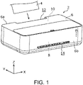
- FIG. 1 is a perspective view showing an appearance of the printing apparatus 2 according to the embodiment.
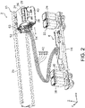
- FIG. 2 is a perspective view showing an extracted part of an internal mechanism of the printing apparatus 2 according to the embodiment.
- FIG. 3 is an enlarged perspective view showing a first tube holder 52 and a second tube holder 54 according to the embodiment.
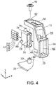
- FIG. 4 is an exploded perspective view showing the first tube holder 52 and the second tube holder 54 according to the embodiment in an exploded manner.
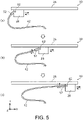
- FIG. 5 is a schematic view showing how an ink tube unit 42 undergoes follow-up deformation along with reciprocating movement of a carriage 28 in a printing unit 10 according to the embodiment.
- a width direction (left-right direction) of the printing apparatus 2 is the X-axis direction
- a depth direction (front-rear direction) of the printing apparatus 2 is the Y-axis direction
- a height direction (up-down direction) of the printing apparatus 2 is the Z-axis direction.
- the printing apparatus 2 is an inkjet printer which prints by ejecting ink to a recording medium 4.
- the recording medium 4 is, for example, plain paper, photo paper, a CD-ROM (compact disc read only memory) having a printable label surface, etc.
- the printing apparatus 2 includes a housing 6, a tank unit 8, and a printing unit 10.
- a supply port 12 for supplying a recording medium 4 to be printed to the inside of the housing 6 is provided at an upper end of a back surface 6a of the housing 6.
- the recording medium 4 is inserted into the supply port 12 from above.
- a supply tray for supporting, from the rear side, the recording medium 4 inserted into the supply port 12 is fixed to the upper end of the back surface 6a of the housing 6.
- a discharge port 14 for discharging the printed recording medium 4 to the outside of the housing 6 is provided at a front surface 6b of the housing 6.
- the recording medium 4 inserted into the supply port 12 is transported inside the housing 6 in a direction (minus direction of the Y-axis) from the supply port 12 toward the discharge port 14 by a transport mechanism (not shown) arranged inside the housing 6.
- the tank unit 8 is arranged inside the housing 6. As shown in FIG. 2 , the tank unit 8 includes a frame 16, a cyan (C) ink tank 18 (an example of an ink tank), a magenta (M) ink tank 20 (an example of the ink tank), a yellow (Y) ink tank 22 (an example of the ink tank), and a black (K) ink tank 24 (an example of the ink tank).
- the cyan ink tank 18, the magenta ink tank 20, the yellow ink tank 22, and the black ink tank 24 are supported by the frame 16 and are arranged outside a carriage 28.
- the cyan ink tank 18 contains cyan ink.
- the magenta ink tank 20 contains magenta ink.
- the yellow ink tank 22 contains yellow ink.
- the black ink tank 24 contains black ink.
- the printing unit 10 is arranged inside the housing 6. As shown in FIG. 2 , the printing unit 10 includes a guide frame 26 and a carriage 28 supported by the guide frame 26.
- the guide frame 26 extends in the width direction (X-axis direction) of the printing apparatus 2.
- the carriage 28 may reciprocate along the guide frame 26 in a predetermined direction (X-axis direction), i.e., in a direction substantially perpendicular to a transport direction of the recording medium 4.
- X-axis direction i.e., in a direction substantially perpendicular to a transport direction of the recording medium 4.
- a shaft part 30 in a columnar shape projecting upward (plus direction of the Z-axis) is formed on an upper surface of the carriage 28.
- a screw hole 32 is formed in the shaft part 30.
- a color ink container 34 and a black ink container 36 are mounted on the carriage 28.
- the color ink container 34 is a container for temporarily storing the cyan ink, the magenta ink, and the yellow ink respectively supplied from the cyan ink tank 18, the magenta ink tank 20, and the yellow ink tank 22.
- a recording head 38 for ejecting the cyan ink, the magenta ink, and the yellow ink stored in the color ink container 34 downward (minus direction of the Z-axis) is arranged at a lower end of the color ink container 34.
- the black ink container 36 is a container for temporarily storing the black ink supplied from the black ink tank 24.
- a recording head 40 for ejecting the black ink stored in the black ink container 36 downward is arranged at a lower end of the black ink container 36.
- the recording medium 4 is transported inside the housing 6 from the supply port 12 toward the discharge port 14, and the carriage 28 reciprocates along the guide frame 26. In this state, each ink is ejected from the recording heads 38 and 40 to the recording medium 4 to print on the recording medium 4.
- the printing apparatus 2 further includes an ink tube unit 42.
- the ink tube unit 42 includes a cyan ink tube 44 (an example of an ink tube), a magenta ink tube 46 (an example of the ink tube), a yellow ink tube 48 (an example of the ink tube), and a black ink tube 50 (an example of the ink tube).
- the cyan ink tube 44, the magenta ink tube 46, the yellow ink tube 48, and the black ink tube 50 are sequentially bundled in a band shape and undergo follow-up deformation along with the reciprocating movement of the carriage 28.
- the cyan ink tube 44 is a flexible tube for connecting the cyan ink tank 18 and the recording head 38 mounted on the carriage 28 to each other.
- the cyan ink tube 44 supplies the cyan ink contained in the cyan ink tank 18 to the recording head 38 via the color ink container 34.
- the magenta ink tube 46 is a flexible tube for connecting the magenta ink tank 20 and the recording head 38 mounted on the carriage 28 to each other.
- the magenta ink tube 46 supplies the magenta ink contained in the magenta ink tank 20 to the recording head 38 via the color ink container 34.
- the yellow ink tube 48 is a flexible tube for connecting the yellow ink tank 22 and the recording head 38 mounted on the carriage 28 to each other.
- the yellow ink tube 48 supplies the yellow ink contained in the yellow ink tank 22 to the recording head 38 via the color ink container 34.
- the black ink tube 50 is a flexible tube for connecting the black ink tank 24 and the recording head 40 mounted on the carriage 28 to each other.
- the black ink tube 50 supplies the black ink contained in the black ink tank 24 to the recording head 40 via the black ink container 36.
- the printing unit 10 further includes a first tube holder 52 and a second tube holder 54.
- the first tube holder 52 is a holder for holding the ink tube unit 42. With the first tube holder 52 holding the ink tube unit 42, it is possible to suppress hanging of the ink tube unit 42 downward.
- the first tube holder 52 includes a horizontal part 56 and a vertical part 58.
- the horizontal part 56 extends in the horizontal direction (in the XY plane) and has a through hole 60 in a circular shape.
- the shaft part 30 of the carriage 28 is rotatably inserted into the through hole 60 of the horizontal part 56.
- the first tube holder 52 is supported to be rotatable on a rotation axis 64 with respect to the carriage 28.
- the rotation axis 64 is an axis which passes through a diameter center of the shaft part 30 and is parallel to an ejection direction (Z-axis direction) of the ink from the recording heads 38 and 40.
- the vertical part 58 extends in the vertical direction (Z-axis direction) from one end of the horizontal part 56 and has an opening 66 in a substantially rectangular shape.
- a first notch 68 is formed at an upper end of the opening 66.
- a second notch 70 is formed at a lower end of the opening 66.
- a third notch 72 is formed at a lateral side of the opening 66.
- the second tube holder 54 is a holder for holding the ink tube unit 42.
- the second tube holder 54 is formed in a substantially rectangular tubular shape, and a vertically long insertion space 74 extending in the horizontal direction is formed inside the second tube holder 54.
- the ink tube unit 42 is inserted into the insertion space 74.
- the cyan ink tube 44, the magenta ink tube 46, the yellow ink tube 48, and the black ink tube 50 are bundled in a band shape in the up-down direction in the insertion space 74.
- the ink tube unit 42 is fixed to the second tube holder 54.
- a first protrusion 76 in a columnar shape is formed on an upper end surface of the second tube holder 54.
- a diameter of the first protrusion 76 is smaller than a size of the first notch 68.
- a second protrusion 78 in a columnar shape is formed at a lower end surface of the second tube holder 54.
- a diameter of the second protrusion 78 is smaller than a size of the second notch 70.
- a third protrusion 80 in a columnar shape is formed on a lateral side surface of the second tube holder 54.
- a diameter of the third protrusion 80 is smaller than a size of the third notch 72.
- the second tube holder 54 is inserted into the opening 66 of the vertical part 58 of the first tube holder 52.
- the first protrusion 76, the second protrusion 78, and the third protrusion 80 of the second tube holder 54 are respectively inserted into the first notch 68, the second notch 70, and the third notch 72 of the first tube holder 52 in a displaceable manner.
- the second tube holder 54 is supported to be displaceable in three axis directions orthogonal to each other with respect to the first tube holder 52.
- the three axis directions above include a first direction (a direction indicated by an arrow P in FIG. 3 ) parallel to the rotation axis 64, a second direction (a direction indicated by an arrow Q in FIG. 3 ) parallel to a long direction of each of the ink tubes 44, 46, 48, and 50 in the second tube holder 54, and a third direction (a direction indicated by an arrow R in FIG. 3 ) parallel to a radial direction of each of the ink tubes 44, 46, 48, and 50 in the second tube holder 54.
- the ink tube unit 42 undergoes follow-up deformation as the carriage 28 reciprocates in a predetermined direction (X-axis direction).
- the first tube holder 52 rotates with respect to the carriage 28 in response to the follow-up deformation of the ink tube unit 42.
- the carriage 28 moves in a direction indicated by a solid line arrow
- the first tube holder 52 rotates in a direction indicated by a solid line arrow with respect to the carriage 28.
- the first tube holder 52 rotates in a direction indicated by a broken line arrow with respect to the carriage 28.
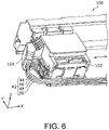
- FIG. 6 is a perspective view showing a carriage 102 of the printing unit 100 according to the comparative example.
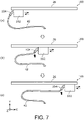
- FIG. 7 is a schematic view showing how an ink tube unit 42 undergoes follow-up deformation along with reciprocating movement of the carriage 102 in the printing unit 100 according to the comparative example.
- the same components as those in FIG. 1 to FIG. 5 are labeled with the same reference signs, and descriptions thereof will be omitted.
- the carriage 102 of the printing unit 100 according to the comparative example is provided with a fixing part 104 for fixing the ink tube unit 42 to the carriage 102.
- the fixing part 104 is fixed with respect to the carriage 102.
- the ink tube unit 42 undergoes follow-up deformation as the carriage 102 reciprocates in a predetermined direction (X-axis direction).
- the posture of the ink tube unit 42 with respect to the fixing part 104 of the carriage 102 changes as the carriage 102 reciprocates. Therefore, a load is applied to a portion (a portion indicated by a thick arrow in (b) and (c) of FIG. 7 ) of the ink tube unit 42 fixed to the fixing part 104 of the carriage 102, and the ink tube unit 42 may be damaged due to accumulation of the load.
- the second tube holder 54 is displaced in the three axis directions orthogonal to each other with respect to the first tube holder 52. With the second tube holder 54, it is possible to absorb the movement of the ink tube unit 42 with respect to the first tube holder 52 in the three axis directions orthogonal to each other.
- the second tube holder 54 being displaced in the first direction with respect to the first tube holder 52, it is possible to absorb the movement of each of the ink tubes 44, 46, 48, and 50 with respect to the first tube holder 52 in the first direction resulting from twisting of each of the ink tubes 44, 46, 48, and 50. Further, with the second tube holder 54 being displaced in the second direction with respect to the first tube holder 52, it is possible to absorb the movement of each of the ink tubes 44, 46, 48, and 50 with respect to the first tube holder 52 in the second direction.
- the ink tube unit 42 includes four ink tubes (i.e., the cyan ink tube 44, the magenta ink tube 46, the yellow ink tube 48, and the black ink tube 50), but the disclosure is not limited thereto and may have, for example, one ink tube, two ink tubes, three ink tubes, or five ink tubes or more.
- the printing apparatus according to the disclosure may be applied as an inkjet printer which prints by, for example, ejecting ink onto a recording medium.
Landscapes
- Ink Jet (AREA)
Abstract
Description
- The disclosure relates to a printing apparatus for printing on a recording medium.
- An ink supply type printing apparatus is conventionally known (see, for example, Patent Document 1). This type of printing apparatus includes a carriage which reciprocates in a predetermined direction and has a recording head, an ink tank which is arranged outside the carriage, and an ink tube which connects the recording head and the ink tank to each other.
- The carriage is provided with a fixing part for fixing the ink tube to the carriage. The ink contained in the ink tank is supplied to the recording head via the ink tube.
- [Patent Document 1]
Japanese Patent Application Laid-Open No. 2001-130020 - In the conventional printing apparatus described above, the ink tube undergoes follow-up deformation as the carriage reciprocates. At this time, the posture of the ink tube with respect to the fixing part of the carriage changes as the carriage reciprocates. Therefore, a load is applied to a portion of the ink tube fixed to the fixing part of the carriage, and the ink tube may be damaged due to accumulation of the load.
- To solve the above problem, an objective of the disclosure is to provide a printing apparatus capable of reducing a load applied to an ink tube.
- To achieve the above objective, a printing apparatus according to an aspect of the disclosure is a printing apparatus for printing on a recording medium and includes a carriage, an ink tank, an ink tube, and a first tube holder. The carriage reciprocates in a predetermined direction with respect to the recording medium and includes a recording head ejecting ink to the recording medium. The ink tank is arranged outside the carriage and is configured to contain ink. The ink tube connects the ink tank and the recording head to each other to supply the ink contained in the ink tank to the recording head, and the ink tube undergoes follow-up deformation along with reciprocating movement of the carriage. The first tube holder is rotatably supported with respect to the carriage and holds the ink tube.
- According to this aspect, the first tube holder is rotatably supported with respect to the carriage and holds the ink tube. Accordingly, the first tube holder rotates with respect to the carriage in response to the follow-up deformation of the ink tube along with the reciprocating movement of the carriage. As a result, it is possible to suppress a forced posture taken by the ink tube with respect to the carriage, and it is possible to reduce the load applied to the ink tube.
- For example, in the printing apparatus according to an aspect of the disclosure, the first tube holder may be rotatable with respect to the carriage on a rotation axis parallel to an ejection direction of the ink from the recording head.
- According to this aspect, the load applied to the ink tube can be effectively reduced.
- For example, in the printing apparatus according to an aspect of the disclosure, the printing apparatus may further include a second tube holder which is supported to be displaceable with respect to the first tube holder and holds the ink tube.
- According to this aspect, with the second tube holder, it is possible to absorb the movement of the ink tube with respect to the first tube holder. As a result, the load applied to the ink tube can be reduced more effectively.
- For example, in the printing apparatus according to an aspect of the disclosure, the second tube holder may be displaceable with respect to the first tube holder in three axis directions orthogonal to each other.
- According to this aspect, with the second tube holder, it is possible to absorb the movement of the ink tube with respect to the first tube holder in the three axis directions orthogonal to each other.
- For example, in the printing apparatus according to an aspect of the disclosure, the three axis directions may include a first direction parallel to the rotation axis, a second direction parallel to a long direction of the ink tube in the second tube holder, and a third direction parallel to a radial direction of the ink tube in the second tube holder.
- According to this aspect, with the second tube holder being displaced in the first direction with respect to the first tube holder, it is possible to absorb the movement of the ink tube with respect to the first tube holder in the first direction resulting from twisting of the ink tube. Further, with the second tube holder being displaced in the second direction with respect to the first tube holder, it is possible to absorb the movement of the ink tube with respect to the first tube holder in the second direction. Further, with the second tube holder being displaced in the third direction with respect to the first tube holder, it is possible to expand a movable range of the movement of the ink tube with respect to the first tube holder in the third direction.
- According to the printing apparatus according to an aspect of the disclosure, the load applied to the ink tube can be reduced.
-
-
FIG. 1 is a perspective view showing an appearance of a printing apparatus according to an embodiment. -
FIG. 2 is a perspective view showing an extracted part of an internal mechanism of the printing apparatus according to the embodiment. -
FIG. 3 is an enlarged perspective view showing a first tube holder and a second tube holder according to the embodiment. -
FIG. 4 is an exploded perspective view showing the first tube holder and the second tube holder according to the embodiment in an exploded manner. -
FIG. 5 is a schematic view showing how an ink tube unit undergoes follow-up deformation along with reciprocating movement of a carriage in a printing unit according to the embodiment. -
FIG. 6 is a perspective view showing a carriage of a printing unit according to a comparative example. -
FIG. 7 is a schematic view showing how an ink tube unit undergoes follow-up deformation along with reciprocating movement of the carriage in the printing unit according to the comparative example. - Hereinafter, embodiments of the disclosure will be described in detail with reference to the drawings. The embodiments described below all show comprehensive or specific examples. Numerical values, shapes, materials, components, arrangement positions of components, connection forms, and the like shown in the following embodiments are exemplary and are not intended to limit the disclosure. Further, among the components in the following embodiments, the components not described in the independent claims will be described as arbitrary components.
- First, a configuration of a
printing apparatus 2 according to an embodiment will be described with reference toFIG. 1 to FIG. 5 .FIG. 1 is a perspective view showing an appearance of theprinting apparatus 2 according to the embodiment.FIG. 2 is a perspective view showing an extracted part of an internal mechanism of theprinting apparatus 2 according to the embodiment.FIG. 3 is an enlarged perspective view showing afirst tube holder 52 and asecond tube holder 54 according to the embodiment.FIG. 4 is an exploded perspective view showing thefirst tube holder 52 and thesecond tube holder 54 according to the embodiment in an exploded manner.FIG. 5 is a schematic view showing how anink tube unit 42 undergoes follow-up deformation along with reciprocating movement of acarriage 28 in aprinting unit 10 according to the embodiment. - In
FIG. 1 to FIG. 4 , a width direction (left-right direction) of theprinting apparatus 2 is the X-axis direction, a depth direction (front-rear direction) of theprinting apparatus 2 is the Y-axis direction, and a height direction (up-down direction) of theprinting apparatus 2 is the Z-axis direction. - As shown in
FIG. 1 , theprinting apparatus 2 is an inkjet printer which prints by ejecting ink to a recording medium 4. The recording medium 4 is, for example, plain paper, photo paper, a CD-ROM (compact disc read only memory) having a printable label surface, etc. As shown inFIG. 1 andFIG. 2 , theprinting apparatus 2 includes ahousing 6, atank unit 8, and aprinting unit 10. - As shown in
FIG. 1 , a supply port 12 for supplying a recording medium 4 to be printed to the inside of thehousing 6 is provided at an upper end of aback surface 6a of thehousing 6. The recording medium 4 is inserted into the supply port 12 from above. Although not shown, a supply tray for supporting, from the rear side, the recording medium 4 inserted into the supply port 12 is fixed to the upper end of theback surface 6a of thehousing 6. Adischarge port 14 for discharging the printed recording medium 4 to the outside of thehousing 6 is provided at afront surface 6b of thehousing 6. - The recording medium 4 inserted into the supply port 12 is transported inside the
housing 6 in a direction (minus direction of the Y-axis) from the supply port 12 toward thedischarge port 14 by a transport mechanism (not shown) arranged inside thehousing 6. - The
tank unit 8 is arranged inside thehousing 6. As shown inFIG. 2 , thetank unit 8 includes aframe 16, a cyan (C) ink tank 18 (an example of an ink tank), a magenta (M) ink tank 20 (an example of the ink tank), a yellow (Y) ink tank 22 (an example of the ink tank), and a black (K) ink tank 24 (an example of the ink tank). Thecyan ink tank 18, themagenta ink tank 20, theyellow ink tank 22, and theblack ink tank 24 are supported by theframe 16 and are arranged outside acarriage 28. - The
cyan ink tank 18 contains cyan ink. Themagenta ink tank 20 contains magenta ink. Theyellow ink tank 22 contains yellow ink. Theblack ink tank 24 contains black ink. - The
printing unit 10 is arranged inside thehousing 6. As shown inFIG. 2 , theprinting unit 10 includes aguide frame 26 and acarriage 28 supported by theguide frame 26. Theguide frame 26 extends in the width direction (X-axis direction) of theprinting apparatus 2. Thecarriage 28 may reciprocate along theguide frame 26 in a predetermined direction (X-axis direction), i.e., in a direction substantially perpendicular to a transport direction of the recording medium 4. As shown inFIG. 4 , ashaft part 30 in a columnar shape projecting upward (plus direction of the Z-axis) is formed on an upper surface of thecarriage 28. Ascrew hole 32 is formed in theshaft part 30. - A
color ink container 34 and ablack ink container 36 are mounted on thecarriage 28. Thecolor ink container 34 is a container for temporarily storing the cyan ink, the magenta ink, and the yellow ink respectively supplied from thecyan ink tank 18, themagenta ink tank 20, and theyellow ink tank 22. Arecording head 38 for ejecting the cyan ink, the magenta ink, and the yellow ink stored in thecolor ink container 34 downward (minus direction of the Z-axis) is arranged at a lower end of thecolor ink container 34. Theblack ink container 36 is a container for temporarily storing the black ink supplied from theblack ink tank 24. Arecording head 40 for ejecting the black ink stored in theblack ink container 36 downward is arranged at a lower end of theblack ink container 36. - At the time of printing, the recording medium 4 is transported inside the
housing 6 from the supply port 12 toward thedischarge port 14, and thecarriage 28 reciprocates along theguide frame 26. In this state, each ink is ejected from the recording heads 38 and 40 to the recording medium 4 to print on the recording medium 4. - As shown in
FIG. 2 , theprinting apparatus 2 further includes anink tube unit 42. Theink tube unit 42 includes a cyan ink tube 44 (an example of an ink tube), a magenta ink tube 46 (an example of the ink tube), a yellow ink tube 48 (an example of the ink tube), and a black ink tube 50 (an example of the ink tube). Thecyan ink tube 44, themagenta ink tube 46, theyellow ink tube 48, and theblack ink tube 50 are sequentially bundled in a band shape and undergo follow-up deformation along with the reciprocating movement of thecarriage 28. - The
cyan ink tube 44 is a flexible tube for connecting thecyan ink tank 18 and therecording head 38 mounted on thecarriage 28 to each other. Thecyan ink tube 44 supplies the cyan ink contained in thecyan ink tank 18 to therecording head 38 via thecolor ink container 34. - The
magenta ink tube 46 is a flexible tube for connecting themagenta ink tank 20 and therecording head 38 mounted on thecarriage 28 to each other. Themagenta ink tube 46 supplies the magenta ink contained in themagenta ink tank 20 to therecording head 38 via thecolor ink container 34. - The
yellow ink tube 48 is a flexible tube for connecting theyellow ink tank 22 and therecording head 38 mounted on thecarriage 28 to each other. Theyellow ink tube 48 supplies the yellow ink contained in theyellow ink tank 22 to therecording head 38 via thecolor ink container 34. - The
black ink tube 50 is a flexible tube for connecting theblack ink tank 24 and therecording head 40 mounted on thecarriage 28 to each other. Theblack ink tube 50 supplies the black ink contained in theblack ink tank 24 to therecording head 40 via theblack ink container 36. - As shown in
FIG. 3 andFIG. 4 , theprinting unit 10 further includes afirst tube holder 52 and asecond tube holder 54. - The
first tube holder 52 is a holder for holding theink tube unit 42. With thefirst tube holder 52 holding theink tube unit 42, it is possible to suppress hanging of theink tube unit 42 downward. Thefirst tube holder 52 includes ahorizontal part 56 and avertical part 58. - The
horizontal part 56 extends in the horizontal direction (in the XY plane) and has a throughhole 60 in a circular shape. Theshaft part 30 of thecarriage 28 is rotatably inserted into the throughhole 60 of thehorizontal part 56. By screwing ascrew 62 into thescrew hole 32 of theshaft part 30 through the throughhole 60 of thehorizontal part 56, thefirst tube holder 52 is supported to be rotatable on arotation axis 64 with respect to thecarriage 28. Herein, therotation axis 64 is an axis which passes through a diameter center of theshaft part 30 and is parallel to an ejection direction (Z-axis direction) of the ink from the recording heads 38 and 40. - The
vertical part 58 extends in the vertical direction (Z-axis direction) from one end of thehorizontal part 56 and has anopening 66 in a substantially rectangular shape. Afirst notch 68 is formed at an upper end of theopening 66. Further, asecond notch 70 is formed at a lower end of theopening 66. Further, athird notch 72 is formed at a lateral side of theopening 66. - The
second tube holder 54 is a holder for holding theink tube unit 42. Thesecond tube holder 54 is formed in a substantially rectangular tubular shape, and a verticallylong insertion space 74 extending in the horizontal direction is formed inside thesecond tube holder 54. Theink tube unit 42 is inserted into theinsertion space 74. Thecyan ink tube 44, themagenta ink tube 46, theyellow ink tube 48, and theblack ink tube 50 are bundled in a band shape in the up-down direction in theinsertion space 74. Theink tube unit 42 is fixed to thesecond tube holder 54. - A
first protrusion 76 in a columnar shape is formed on an upper end surface of thesecond tube holder 54. A diameter of thefirst protrusion 76 is smaller than a size of thefirst notch 68. Asecond protrusion 78 in a columnar shape is formed at a lower end surface of thesecond tube holder 54. A diameter of thesecond protrusion 78 is smaller than a size of thesecond notch 70. Athird protrusion 80 in a columnar shape is formed on a lateral side surface of thesecond tube holder 54. A diameter of thethird protrusion 80 is smaller than a size of thethird notch 72. - The
second tube holder 54 is inserted into theopening 66 of thevertical part 58 of thefirst tube holder 52. At this time, thefirst protrusion 76, thesecond protrusion 78, and thethird protrusion 80 of thesecond tube holder 54 are respectively inserted into thefirst notch 68, thesecond notch 70, and thethird notch 72 of thefirst tube holder 52 in a displaceable manner. Accordingly, thesecond tube holder 54 is supported to be displaceable in three axis directions orthogonal to each other with respect to thefirst tube holder 52. - The three axis directions above include a first direction (a direction indicated by an arrow P in
FIG. 3 ) parallel to therotation axis 64, a second direction (a direction indicated by an arrow Q inFIG. 3 ) parallel to a long direction of each of theink tubes second tube holder 54, and a third direction (a direction indicated by an arrow R inFIG. 3 ) parallel to a radial direction of each of theink tubes second tube holder 54. - As shown in (a), (b), and (c) of
FIG. 5 , theink tube unit 42 undergoes follow-up deformation as thecarriage 28 reciprocates in a predetermined direction (X-axis direction). At this time, thefirst tube holder 52 rotates with respect to thecarriage 28 in response to the follow-up deformation of theink tube unit 42. In other words, in (a), (b), and (c) ofFIG. 5 , when thecarriage 28 moves in a direction indicated by a solid line arrow, thefirst tube holder 52 rotates in a direction indicated by a solid line arrow with respect to thecarriage 28. On the other hand, when thecarriage 28 moves in a direction indicated by a broken line arrow, thefirst tube holder 52 rotates in a direction indicated by a broken line arrow with respect to thecarriage 28. - Hereinafter, a configuration of a
printing unit 100 according to a comparative example will be described with reference toFIG. 6 andFIG. 7 .FIG. 6 is a perspective view showing acarriage 102 of theprinting unit 100 according to the comparative example.FIG. 7 is a schematic view showing how anink tube unit 42 undergoes follow-up deformation along with reciprocating movement of thecarriage 102 in theprinting unit 100 according to the comparative example. InFIG. 6 andFIG. 7 , the same components as those inFIG. 1 to FIG. 5 are labeled with the same reference signs, and descriptions thereof will be omitted. - As shown in
FIG. 6 , thecarriage 102 of theprinting unit 100 according to the comparative example is provided with a fixingpart 104 for fixing theink tube unit 42 to thecarriage 102. The fixingpart 104 is fixed with respect to thecarriage 102. - As shown in (a), (b), and (c) of
FIG. 7 , in theprinting unit 100 according to the comparative example, theink tube unit 42 undergoes follow-up deformation as thecarriage 102 reciprocates in a predetermined direction (X-axis direction). At this time, the posture of theink tube unit 42 with respect to the fixingpart 104 of thecarriage 102 changes as thecarriage 102 reciprocates. Therefore, a load is applied to a portion (a portion indicated by a thick arrow in (b) and (c) ofFIG. 7 ) of theink tube unit 42 fixed to the fixingpart 104 of thecarriage 102, and theink tube unit 42 may be damaged due to accumulation of the load. - On the other hand, in the
printing apparatus 2 according to the embodiment, as shown in (a), (b), and (c) ofFIG. 5 , in response to the follow-up deformation of theink tube unit 42 along with the reciprocating movement of thecarriage 28, thefirst tube holder 52 rotates with respect to thecarriage 28. As a result, it is possible to suppress a forced posture taken by theink tube unit 42 with respect to thecarriage 28, and it is possible to reduce the load applied to theink tube unit 42. - Further, in response to the follow-up deformation of the
ink tube unit 42 along with the reciprocating movement of thecarriage 28, thesecond tube holder 54 is displaced in the three axis directions orthogonal to each other with respect to thefirst tube holder 52. With thesecond tube holder 54, it is possible to absorb the movement of theink tube unit 42 with respect to thefirst tube holder 52 in the three axis directions orthogonal to each other. - Specifically, with the
second tube holder 54 being displaced in the first direction with respect to thefirst tube holder 52, it is possible to absorb the movement of each of theink tubes first tube holder 52 in the first direction resulting from twisting of each of theink tubes second tube holder 54 being displaced in the second direction with respect to thefirst tube holder 52, it is possible to absorb the movement of each of theink tubes first tube holder 52 in the second direction. Further, with thesecond tube holder 54 being displaced in the third direction with respect to thefirst tube holder 52, it is possible to expand a movable range of the movement (i.e., movement in the rotation direction of the first tube holder 52) of each of theink tubes first tube holder 52 in the third direction. - Although the printing apparatus according to the embodiment of the disclosure has been described above, the disclosure is not limited to the above-described embodiment.
- In the above embodiment, the
ink tube unit 42 includes four ink tubes (i.e., thecyan ink tube 44, themagenta ink tube 46, theyellow ink tube 48, and the black ink tube 50), but the disclosure is not limited thereto and may have, for example, one ink tube, two ink tubes, three ink tubes, or five ink tubes or more. - The printing apparatus according to the disclosure may be applied as an inkjet printer which prints by, for example, ejecting ink onto a recording medium.
-
- 2
- Printing apparatus
- 4
- Recording medium
- 6
- Housing
- 6a
- Back surface
- 6b
- Front surface
- 8
- Tank unit
- 10, 100
- Printing unit
- 12
- Supply port
- 14
- Discharge port
- 16
- Frame
- 18
- Cyan ink tank
- 20
- Magenta ink tank
- 22
- Yellow ink tank
- 24
- Black ink tank
- 26
- Guide frame
- 28, 102
- Carriage
- 30
- Shaft part
- 32
- Screw hole
- 34
- Color ink container
- 36
- Black ink container
- 38, 40
- Recording head
- 42
- Ink tube unit
- 44
- Cyan ink tube
- 46
- Magenta ink tube
- 48
- Yellow ink tube
- 50
- Black ink tube
- 52
- First tube holder
- 54
- Second tube holder
- 56
- Horizontal part
- 58
- Vertical part
- 60
- Through hole
- 62
- Screw
- 64
- Rotation axis
- 66
- Opening
- 68
- First notch
- 70
- Second notch
- 72
- Third notch
- 74
- Insertion space
- 76
- First protrusion
- 78
- Second protrusion
- 80
- Third protrusion
- 104
- Fixing part
Claims (5)
- A printing apparatus (2) for printing on a recording medium (4), the printing apparatus (2) comprising:a carriage (28) which reciprocates in a predetermined direction with respect to the recording medium (4) and comprises a recording head (38, 40) ejecting ink to the recording medium (4);an ink tank (18, 20, 22, 24) which is arranged outside the carriage (28) and is configured to contain ink;an ink tube (44, 46, 48, 50) which connects the ink tank (18, 20, 22, 24) and the recording head (38, 40) to each other to supply the ink contained in the ink tank (18, 20, 22, 24) to the recording head (38, 40), wherein the ink tube (44, 46, 48, 50) undergoes follow-up deformation along with reciprocating movement of the carriage (28); anda first tube holder (52) which is rotatably supported with respect to the carriage (28) and holds the ink tube (44, 46, 48, 50).
- The printing apparatus (2) according to claim 1, wherein the first tube holder (52) is rotatable with respect to the carriage (28) on a rotation axis parallel to an ejection direction of the ink from the recording head (38, 40).
- The printing apparatus (2) according to claim 2, further comprising a second tube holder (54) which is supported to be displaceable with respect to the first tube holder (52) and holds the ink tube (44, 46, 48, 50).
- The printing apparatus (2) according to claim 3, wherein the second tube holder (54) is displaceable with respect to the first tube holder (52) in three axis directions orthogonal to each other.
- The printing apparatus (2) according to claim 4, wherein the three axis directions comprise:a first direction parallel to the rotation axis;a second direction parallel to a long direction of the ink tube (44, 46, 48, 50) in the second tube holder (54); anda third direction parallel to a radial direction of the ink tube (44, 46, 48, 50) in the second tube holder (54).
Applications Claiming Priority (1)
| Application Number | Priority Date | Filing Date | Title |
|---|---|---|---|
| JP2021068528A JP2022163530A (en) | 2021-04-14 | 2021-04-14 | Printing device |
Publications (2)
| Publication Number | Publication Date |
|---|---|
| EP4074510A1 true EP4074510A1 (en) | 2022-10-19 |
| EP4074510B1 EP4074510B1 (en) | 2023-08-16 |
Family
ID=80780497
Family Applications (1)
| Application Number | Title | Priority Date | Filing Date |
|---|---|---|---|
| EP22162175.8A Active EP4074510B1 (en) | 2021-04-14 | 2022-03-15 | Printing apparatus |
Country Status (4)
| Country | Link |
|---|---|
| US (1) | US11919312B2 (en) |
| EP (1) | EP4074510B1 (en) |
| JP (1) | JP2022163530A (en) |
| CN (1) | CN115195299B (en) |
Citations (3)
| Publication number | Priority date | Publication date | Assignee | Title |
|---|---|---|---|---|
| JP2001130020A (en) | 1999-11-02 | 2001-05-15 | Seiko Epson Corp | Inkjet printer |
| JP2006015706A (en) * | 2004-07-05 | 2006-01-19 | Ricoh Co Ltd | Inkjet recording device |
| US20090167825A1 (en) * | 2007-12-28 | 2009-07-02 | Brother Kogyo Kabushiki Kaisha | Movement apparatus and image recording apparatus |
Family Cites Families (14)
| Publication number | Priority date | Publication date | Assignee | Title |
|---|---|---|---|---|
| JP3029498B2 (en) * | 1992-02-26 | 2000-04-04 | キヤノン株式会社 | Ink jet recording device |
| DE19923291B4 (en) * | 1999-05-21 | 2004-10-07 | Tally Computerdrucker Gmbh | Ink printer with an ink-liquid compound for one or more ink colors |
| JP2005035032A (en) * | 2003-07-16 | 2005-02-10 | Seiko Epson Corp | Inkjet recording apparatus and liquid ejecting apparatus |
| JP4730090B2 (en) * | 2005-12-28 | 2011-07-20 | ブラザー工業株式会社 | Image recording device |
| JP2007245349A (en) * | 2006-03-13 | 2007-09-27 | Canon Inc | Inkjet recording device |
| TW200924995A (en) * | 2007-12-14 | 2009-06-16 | Qisda Corp | Inkjet device |
| JP5586935B2 (en) * | 2009-12-17 | 2014-09-10 | キヤノン株式会社 | Inkjet recording device |
| JP6021294B2 (en) * | 2010-09-14 | 2016-11-09 | セイコーエプソン株式会社 | Inkjet recording device |
| JP2012158038A (en) * | 2011-01-31 | 2012-08-23 | Canon Inc | Printing apparatus |
| WO2014024392A1 (en) * | 2012-08-10 | 2014-02-13 | セイコーエプソン株式会社 | Liquid ejection device |
| CN102991133B (en) * | 2012-12-10 | 2015-08-12 | 珠海天威飞马打印耗材有限公司 | Line-at-a-time printer and cleaning method |
| JP5958590B2 (en) * | 2015-04-13 | 2016-08-02 | セイコーエプソン株式会社 | Inkjet recording device |
| CN108016133B (en) * | 2016-11-04 | 2019-12-03 | 精工爱普生株式会社 | Liquid injection apparatus |
| JP7275604B2 (en) * | 2019-01-31 | 2023-05-18 | 株式会社リコー | Mobile object, equipment for ejecting liquid |
-
2021
- 2021-04-14 JP JP2021068528A patent/JP2022163530A/en active Pending
-
2022
- 2022-03-15 EP EP22162175.8A patent/EP4074510B1/en active Active
- 2022-03-15 US US17/695,807 patent/US11919312B2/en active Active
- 2022-03-21 CN CN202210276013.6A patent/CN115195299B/en not_active Expired - Fee Related
Patent Citations (3)
| Publication number | Priority date | Publication date | Assignee | Title |
|---|---|---|---|---|
| JP2001130020A (en) | 1999-11-02 | 2001-05-15 | Seiko Epson Corp | Inkjet printer |
| JP2006015706A (en) * | 2004-07-05 | 2006-01-19 | Ricoh Co Ltd | Inkjet recording device |
| US20090167825A1 (en) * | 2007-12-28 | 2009-07-02 | Brother Kogyo Kabushiki Kaisha | Movement apparatus and image recording apparatus |
Also Published As
| Publication number | Publication date |
|---|---|
| US11919312B2 (en) | 2024-03-05 |
| US20220332120A1 (en) | 2022-10-20 |
| EP4074510B1 (en) | 2023-08-16 |
| JP2022163530A (en) | 2022-10-26 |
| CN115195299B (en) | 2024-08-16 |
| CN115195299A (en) | 2022-10-18 |
Similar Documents
| Publication | Publication Date | Title |
|---|---|---|
| EP3144154B1 (en) | Terminal connection assembly and cartridge | |
| US11491794B2 (en) | Recording apparatus | |
| US9834001B2 (en) | Recording apparatus | |
| US8167415B2 (en) | Liquid container | |
| US11807015B2 (en) | Cartridge | |
| JP2007268978A (en) | Protection device for ink cartridge storage device | |
| WO2013132810A1 (en) | Liquid ejection device | |
| EP4074510B1 (en) | Printing apparatus | |
| JP2010018024A (en) | Liquid discharge device, control method for the same, and liquid tank | |
| JP2007268980A (en) | Protection device for ink cartridge storage device | |
| JP6175849B2 (en) | Liquid supply device and liquid consumption device | |
| JP6056181B2 (en) | Recording device | |
| JP5991002B2 (en) | Recording device | |
| JP5875288B2 (en) | Liquid ejector | |
| JP2018065363A (en) | Supply device | |
| JP6969178B2 (en) | Supply device | |
| JP2008023763A (en) | Image forming apparatus | |
| US11117381B2 (en) | Printer | |
| JP7414915B2 (en) | Liquid storage container and liquid discharge device | |
| JP6079254B2 (en) | Ink supply system | |
| JP2013123847A (en) | Liquid supply system | |
| JP4544406B2 (en) | Recording device | |
| JP2007237677A (en) | Inkjet recording device | |
| JP4547973B2 (en) | Inkjet recording device | |
| JP2016132109A (en) | Liquid supply unit, liquid injection system |
Legal Events
| Date | Code | Title | Description |
|---|---|---|---|
| PUAI | Public reference made under article 153(3) epc to a published international application that has entered the european phase |
Free format text: ORIGINAL CODE: 0009012 |
|
| STAA | Information on the status of an ep patent application or granted ep patent |
Free format text: STATUS: THE APPLICATION HAS BEEN PUBLISHED |
|
| AK | Designated contracting states |
Kind code of ref document: A1 Designated state(s): AL AT BE BG CH CY CZ DE DK EE ES FI FR GB GR HR HU IE IS IT LI LT LU LV MC MK MT NL NO PL PT RO RS SE SI SK SM TR |
|
| STAA | Information on the status of an ep patent application or granted ep patent |
Free format text: STATUS: REQUEST FOR EXAMINATION WAS MADE |
|
| 17P | Request for examination filed |
Effective date: 20221130 |
|
| RBV | Designated contracting states (corrected) |
Designated state(s): AL AT BE BG CH CY CZ DE DK EE ES FI FR GB GR HR HU IE IS IT LI LT LU LV MC MK MT NL NO PL PT RO RS SE SI SK SM TR |
|
| GRAP | Despatch of communication of intention to grant a patent |
Free format text: ORIGINAL CODE: EPIDOSNIGR1 |
|
| STAA | Information on the status of an ep patent application or granted ep patent |
Free format text: STATUS: GRANT OF PATENT IS INTENDED |
|
| RIC1 | Information provided on ipc code assigned before grant |
Ipc: B41J 29/13 20060101ALI20230313BHEP Ipc: B41J 2/175 20060101AFI20230313BHEP |
|
| INTG | Intention to grant announced |
Effective date: 20230331 |
|
| GRAS | Grant fee paid |
Free format text: ORIGINAL CODE: EPIDOSNIGR3 |
|
| GRAA | (expected) grant |
Free format text: ORIGINAL CODE: 0009210 |
|
| STAA | Information on the status of an ep patent application or granted ep patent |
Free format text: STATUS: THE PATENT HAS BEEN GRANTED |
|
| AK | Designated contracting states |
Kind code of ref document: B1 Designated state(s): AL AT BE BG CH CY CZ DE DK EE ES FI FR GB GR HR HU IE IS IT LI LT LU LV MC MK MT NL NO PL PT RO RS SE SI SK SM TR |
|
| REG | Reference to a national code |
Ref country code: CH Ref legal event code: EP |
|
| REG | Reference to a national code |
Ref country code: DE Ref legal event code: R096 Ref document number: 602022000334 Country of ref document: DE |
|
| REG | Reference to a national code |
Ref country code: IE Ref legal event code: FG4D |
|
| REG | Reference to a national code |
Ref country code: LT Ref legal event code: MG9D |
|
| REG | Reference to a national code |
Ref country code: NL Ref legal event code: MP Effective date: 20230816 |
|
| REG | Reference to a national code |
Ref country code: AT Ref legal event code: MK05 Ref document number: 1599675 Country of ref document: AT Kind code of ref document: T Effective date: 20230816 |
|
| PG25 | Lapsed in a contracting state [announced via postgrant information from national office to epo] |
Ref country code: GR Free format text: LAPSE BECAUSE OF FAILURE TO SUBMIT A TRANSLATION OF THE DESCRIPTION OR TO PAY THE FEE WITHIN THE PRESCRIBED TIME-LIMIT Effective date: 20231117 |
|
| PG25 | Lapsed in a contracting state [announced via postgrant information from national office to epo] |
Ref country code: IS Free format text: LAPSE BECAUSE OF FAILURE TO SUBMIT A TRANSLATION OF THE DESCRIPTION OR TO PAY THE FEE WITHIN THE PRESCRIBED TIME-LIMIT Effective date: 20231216 |
|
| PG25 | Lapsed in a contracting state [announced via postgrant information from national office to epo] |
Ref country code: SE Free format text: LAPSE BECAUSE OF FAILURE TO SUBMIT A TRANSLATION OF THE DESCRIPTION OR TO PAY THE FEE WITHIN THE PRESCRIBED TIME-LIMIT Effective date: 20230816 Ref country code: RS Free format text: LAPSE BECAUSE OF FAILURE TO SUBMIT A TRANSLATION OF THE DESCRIPTION OR TO PAY THE FEE WITHIN THE PRESCRIBED TIME-LIMIT Effective date: 20230816 Ref country code: PT Free format text: LAPSE BECAUSE OF FAILURE TO SUBMIT A TRANSLATION OF THE DESCRIPTION OR TO PAY THE FEE WITHIN THE PRESCRIBED TIME-LIMIT Effective date: 20231218 Ref country code: NO Free format text: LAPSE BECAUSE OF FAILURE TO SUBMIT A TRANSLATION OF THE DESCRIPTION OR TO PAY THE FEE WITHIN THE PRESCRIBED TIME-LIMIT Effective date: 20231116 Ref country code: NL Free format text: LAPSE BECAUSE OF FAILURE TO SUBMIT A TRANSLATION OF THE DESCRIPTION OR TO PAY THE FEE WITHIN THE PRESCRIBED TIME-LIMIT Effective date: 20230816 Ref country code: LV Free format text: LAPSE BECAUSE OF FAILURE TO SUBMIT A TRANSLATION OF THE DESCRIPTION OR TO PAY THE FEE WITHIN THE PRESCRIBED TIME-LIMIT Effective date: 20230816 Ref country code: LT Free format text: LAPSE BECAUSE OF FAILURE TO SUBMIT A TRANSLATION OF THE DESCRIPTION OR TO PAY THE FEE WITHIN THE PRESCRIBED TIME-LIMIT Effective date: 20230816 Ref country code: IS Free format text: LAPSE BECAUSE OF FAILURE TO SUBMIT A TRANSLATION OF THE DESCRIPTION OR TO PAY THE FEE WITHIN THE PRESCRIBED TIME-LIMIT Effective date: 20231216 Ref country code: HR Free format text: LAPSE BECAUSE OF FAILURE TO SUBMIT A TRANSLATION OF THE DESCRIPTION OR TO PAY THE FEE WITHIN THE PRESCRIBED TIME-LIMIT Effective date: 20230816 Ref country code: GR Free format text: LAPSE BECAUSE OF FAILURE TO SUBMIT A TRANSLATION OF THE DESCRIPTION OR TO PAY THE FEE WITHIN THE PRESCRIBED TIME-LIMIT Effective date: 20231117 Ref country code: FI Free format text: LAPSE BECAUSE OF FAILURE TO SUBMIT A TRANSLATION OF THE DESCRIPTION OR TO PAY THE FEE WITHIN THE PRESCRIBED TIME-LIMIT Effective date: 20230816 Ref country code: AT Free format text: LAPSE BECAUSE OF FAILURE TO SUBMIT A TRANSLATION OF THE DESCRIPTION OR TO PAY THE FEE WITHIN THE PRESCRIBED TIME-LIMIT Effective date: 20230816 |
|
| PG25 | Lapsed in a contracting state [announced via postgrant information from national office to epo] |
Ref country code: PL Free format text: LAPSE BECAUSE OF FAILURE TO SUBMIT A TRANSLATION OF THE DESCRIPTION OR TO PAY THE FEE WITHIN THE PRESCRIBED TIME-LIMIT Effective date: 20230816 |
|
| PG25 | Lapsed in a contracting state [announced via postgrant information from national office to epo] |
Ref country code: ES Free format text: LAPSE BECAUSE OF FAILURE TO SUBMIT A TRANSLATION OF THE DESCRIPTION OR TO PAY THE FEE WITHIN THE PRESCRIBED TIME-LIMIT Effective date: 20230816 |
|
| PG25 | Lapsed in a contracting state [announced via postgrant information from national office to epo] |
Ref country code: SM Free format text: LAPSE BECAUSE OF FAILURE TO SUBMIT A TRANSLATION OF THE DESCRIPTION OR TO PAY THE FEE WITHIN THE PRESCRIBED TIME-LIMIT Effective date: 20230816 Ref country code: RO Free format text: LAPSE BECAUSE OF FAILURE TO SUBMIT A TRANSLATION OF THE DESCRIPTION OR TO PAY THE FEE WITHIN THE PRESCRIBED TIME-LIMIT Effective date: 20230816 Ref country code: ES Free format text: LAPSE BECAUSE OF FAILURE TO SUBMIT A TRANSLATION OF THE DESCRIPTION OR TO PAY THE FEE WITHIN THE PRESCRIBED TIME-LIMIT Effective date: 20230816 Ref country code: EE Free format text: LAPSE BECAUSE OF FAILURE TO SUBMIT A TRANSLATION OF THE DESCRIPTION OR TO PAY THE FEE WITHIN THE PRESCRIBED TIME-LIMIT Effective date: 20230816 Ref country code: DK Free format text: LAPSE BECAUSE OF FAILURE TO SUBMIT A TRANSLATION OF THE DESCRIPTION OR TO PAY THE FEE WITHIN THE PRESCRIBED TIME-LIMIT Effective date: 20230816 Ref country code: CZ Free format text: LAPSE BECAUSE OF FAILURE TO SUBMIT A TRANSLATION OF THE DESCRIPTION OR TO PAY THE FEE WITHIN THE PRESCRIBED TIME-LIMIT Effective date: 20230816 Ref country code: SK Free format text: LAPSE BECAUSE OF FAILURE TO SUBMIT A TRANSLATION OF THE DESCRIPTION OR TO PAY THE FEE WITHIN THE PRESCRIBED TIME-LIMIT Effective date: 20230816 |
|
| PGFP | Annual fee paid to national office [announced via postgrant information from national office to epo] |
Ref country code: DE Payment date: 20240130 Year of fee payment: 3 |
|
| REG | Reference to a national code |
Ref country code: DE Ref legal event code: R097 Ref document number: 602022000334 Country of ref document: DE |
|
| PLBE | No opposition filed within time limit |
Free format text: ORIGINAL CODE: 0009261 |
|
| STAA | Information on the status of an ep patent application or granted ep patent |
Free format text: STATUS: NO OPPOSITION FILED WITHIN TIME LIMIT |
|
| 26N | No opposition filed |
Effective date: 20240517 |
|
| PG25 | Lapsed in a contracting state [announced via postgrant information from national office to epo] |
Ref country code: IT Free format text: LAPSE BECAUSE OF FAILURE TO SUBMIT A TRANSLATION OF THE DESCRIPTION OR TO PAY THE FEE WITHIN THE PRESCRIBED TIME-LIMIT Effective date: 20230816 Ref country code: SI Free format text: LAPSE BECAUSE OF FAILURE TO SUBMIT A TRANSLATION OF THE DESCRIPTION OR TO PAY THE FEE WITHIN THE PRESCRIBED TIME-LIMIT Effective date: 20230816 |
|
| PG25 | Lapsed in a contracting state [announced via postgrant information from national office to epo] |
Ref country code: BG Free format text: LAPSE BECAUSE OF FAILURE TO SUBMIT A TRANSLATION OF THE DESCRIPTION OR TO PAY THE FEE WITHIN THE PRESCRIBED TIME-LIMIT Effective date: 20230816 |
|
| PG25 | Lapsed in a contracting state [announced via postgrant information from national office to epo] |
Ref country code: LU Free format text: LAPSE BECAUSE OF NON-PAYMENT OF DUE FEES Effective date: 20240315 |
|
| PG25 | Lapsed in a contracting state [announced via postgrant information from national office to epo] |
Ref country code: MC Free format text: LAPSE BECAUSE OF FAILURE TO SUBMIT A TRANSLATION OF THE DESCRIPTION OR TO PAY THE FEE WITHIN THE PRESCRIBED TIME-LIMIT Effective date: 20230816 |
|
| PG25 | Lapsed in a contracting state [announced via postgrant information from national office to epo] |
Ref country code: MC Free format text: LAPSE BECAUSE OF FAILURE TO SUBMIT A TRANSLATION OF THE DESCRIPTION OR TO PAY THE FEE WITHIN THE PRESCRIBED TIME-LIMIT Effective date: 20230816 Ref country code: LU Free format text: LAPSE BECAUSE OF NON-PAYMENT OF DUE FEES Effective date: 20240315 Ref country code: BG Free format text: LAPSE BECAUSE OF FAILURE TO SUBMIT A TRANSLATION OF THE DESCRIPTION OR TO PAY THE FEE WITHIN THE PRESCRIBED TIME-LIMIT Effective date: 20230816 |
|
| REG | Reference to a national code |
Ref country code: BE Ref legal event code: MM Effective date: 20240331 |
|
| PG25 | Lapsed in a contracting state [announced via postgrant information from national office to epo] |
Ref country code: BE Free format text: LAPSE BECAUSE OF NON-PAYMENT OF DUE FEES Effective date: 20240331 |
|
| PG25 | Lapsed in a contracting state [announced via postgrant information from national office to epo] |
Ref country code: FR Free format text: LAPSE BECAUSE OF NON-PAYMENT OF DUE FEES Effective date: 20240331 |
|
| PG25 | Lapsed in a contracting state [announced via postgrant information from national office to epo] |
Ref country code: IE Free format text: LAPSE BECAUSE OF NON-PAYMENT OF DUE FEES Effective date: 20240315 |
|
| PG25 | Lapsed in a contracting state [announced via postgrant information from national office to epo] |
Ref country code: IE Free format text: LAPSE BECAUSE OF NON-PAYMENT OF DUE FEES Effective date: 20240315 Ref country code: FR Free format text: LAPSE BECAUSE OF NON-PAYMENT OF DUE FEES Effective date: 20240331 Ref country code: BE Free format text: LAPSE BECAUSE OF NON-PAYMENT OF DUE FEES Effective date: 20240331 |
|
| REG | Reference to a national code |
Ref country code: GB Ref legal event code: 732E Free format text: REGISTERED BETWEEN 20250529 AND 20250604 |
|
| REG | Reference to a national code |
Ref country code: DE Ref legal event code: R081 Ref document number: 602022000334 Country of ref document: DE Owner name: BRADY WORLDWIDE, INC., MILWAUKEE, US Free format text: FORMER OWNER: FUNAI ELECTRIC CO., LTD., DAITO, OSAKA, JP Ref country code: DE Ref legal event code: R082 Ref document number: 602022000334 Country of ref document: DE Representative=s name: BOULT WADE TENNANT LLP, DE |
|
| PG25 | Lapsed in a contracting state [announced via postgrant information from national office to epo] |
Ref country code: CY Free format text: LAPSE BECAUSE OF FAILURE TO SUBMIT A TRANSLATION OF THE DESCRIPTION OR TO PAY THE FEE WITHIN THE PRESCRIBED TIME-LIMIT; INVALID AB INITIO Effective date: 20220315 |
|
| REG | Reference to a national code |
Ref country code: DE Ref legal event code: R119 Ref document number: 602022000334 Country of ref document: DE |
|
| REG | Reference to a national code |
Ref country code: CH Ref legal event code: H13 Free format text: ST27 STATUS EVENT CODE: U-0-0-H10-H13 (AS PROVIDED BY THE NATIONAL OFFICE) Effective date: 20251023 |
|
| PG25 | Lapsed in a contracting state [announced via postgrant information from national office to epo] |
Ref country code: TR Free format text: LAPSE BECAUSE OF FAILURE TO SUBMIT A TRANSLATION OF THE DESCRIPTION OR TO PAY THE FEE WITHIN THE PRESCRIBED TIME-LIMIT Effective date: 20230816 |
|
| PG25 | Lapsed in a contracting state [announced via postgrant information from national office to epo] |
Ref country code: DE Free format text: LAPSE BECAUSE OF NON-PAYMENT OF DUE FEES Effective date: 20251001 |
|
| PG25 | Lapsed in a contracting state [announced via postgrant information from national office to epo] |
Ref country code: CH Free format text: LAPSE BECAUSE OF NON-PAYMENT OF DUE FEES Effective date: 20250331 |
|
| PG25 | Lapsed in a contracting state [announced via postgrant information from national office to epo] |
Ref country code: CH Free format text: THE PATENT HAS BEEN ANNULLED BY A DECISION OF A NATIONAL AUTHORITY Effective date: 20250331 |