EP4074475A1 - Remote control device - Google Patents
Remote control device Download PDFInfo
- Publication number
- EP4074475A1 EP4074475A1 EP20898132.4A EP20898132A EP4074475A1 EP 4074475 A1 EP4074475 A1 EP 4074475A1 EP 20898132 A EP20898132 A EP 20898132A EP 4074475 A1 EP4074475 A1 EP 4074475A1
- Authority
- EP
- European Patent Office
- Prior art keywords
- arm
- user interface
- link
- control device
- remote control
- Prior art date
- Legal status (The legal status is an assumption and is not a legal conclusion. Google has not performed a legal analysis and makes no representation as to the accuracy of the status listed.)
- Granted
Links
Images

Classifications
-
- B—PERFORMING OPERATIONS; TRANSPORTING
- B25—HAND TOOLS; PORTABLE POWER-DRIVEN TOOLS; MANIPULATORS
- B25J—MANIPULATORS; CHAMBERS PROVIDED WITH MANIPULATION DEVICES
- B25J13/00—Controls for manipulators
- B25J13/02—Hand grip control means
- B25J13/025—Hand grip control means comprising haptic means
-
- B—PERFORMING OPERATIONS; TRANSPORTING
- B25—HAND TOOLS; PORTABLE POWER-DRIVEN TOOLS; MANIPULATORS
- B25J—MANIPULATORS; CHAMBERS PROVIDED WITH MANIPULATION DEVICES
- B25J19/00—Accessories fitted to manipulators, e.g. for monitoring, for viewing; Safety devices combined with or specially adapted for use in connection with manipulators
- B25J19/0008—Balancing devices
- B25J19/0016—Balancing devices using springs
Definitions
- the present disclosure relates to a remote control device for a remote control of an articulated robot etc.
- a robot or machinery which is used in a place where people are difficult to enter etc., may be remotely controlled.
- control devices for remotely controlling the robot or machinery
- some control devices carry out a force-sense control of the control device (master) and the robot (slave) using a bilateral method.
- the force-sense control by the bilateral method may also be referred to as “the bilateral control.”
- the control device which performs the bilateral control needs to carry out a force-sense feedback of a kinesthetic sense which acts on the robot or machinery to a user, and there are some control devices provided with a plurality of actuators. Some control devices use motors as the actuators.
- a remote control device in which a user can perform the control while placing his/her elbows with his/her wrists so that he/she does not get tired even if he/she uses the device for a long period of time (for example, see Patent Document 1).
- the user can perform the remote control by holding interface parts (grips) and tilting coupling members coupled to armrest members, and the force-sense feedback to the user is performed by motors provided inside the coupling members.
- a manipulator drive unit which operates a manipulator is fixed to a bracket of a spherical surface parallel link, and the spherical surface parallel link is driven by a link drive unit (for example, see Patent Document 2).
- the remote center at which the manipulator is operated is acquired by the link drive unit of the spherical surface parallel link.
- Patent Document 1 described above is the remote control device which is operated while the operator places the elbows including the wrists, the structure will be complicated if the operating range of the user interface is expanded to expand the operating range of the robot. In addition, since the places at which the operator puts the elbows are limited, the robot and machinery to be remotely controlled are limited.
- one purpose of the present disclosure is to provide a remote control device, capable of reducing the size of a configuration around a user interface, and obtaining the expanded operating range.
- the present disclosure includes a first arm supported by a base part, a second arm connected to a tip-end part of the first arm, two rotary bodies disposed side by side at a tip-end part of the second arm, a link structure in which link members are fixed to the two rotary bodies, respectively, and a user interface attached to the link structure.
- the two rotary bodies are independently and rotatably supported by respective coaxial drive shafts disposed horizontally.
- the user interface is pivotable with respect to the second arm on each of mutually-perpendicular three axes passing through a center point of the link structure.
- the link structure is disposed at the lateral side of the rotary bodies so that the center point is located on an axis of the two drive shafts.
- the user interface is attached to the link structure on an axis of a rotation shaft passing through the center point.
- the "link structure" in the documents of the present specification and the claims refers to one including the plurality of link members each of which moves independently with respect to the center point of the three axes.
- the three axes are three axes of a pitch axis, a roll axis, and a yaw axis.
- the user interface since the user interface is attached to the link structure which is disposed at the lateral side of the two rotary bodies disposed side by side at the tip-end part of the second arm and on the axis of the drive shafts of the rotary bodies, the user interface can be operated within a large operating range.
- the user interface since the user interface is disposed at the link structure disposed at the lateral side of the rotary bodies, the size of the configuration around the user interface can be reduced.
- a remote control device which is capable of reducing the size of a configuration around a user interface, and obtaining the expanded operating range, can be provided.
- a remote control device 1 in which a user interface 30 is operated with a single hand is described as an example.
- a case where an articulated robot (not illustrated) is remotely controlled by the remote control device 1 is described as an example.
- the remote control device 1 and the articulated robot (hereinafter, simply referred to as "the robot") are force-sense controlled by a bilateral method (bilaterally controlled). Since the bilateral control can utilize a known method, detailed description thereof is omitted.
- a motor for example, a servomotor
- the concept of front and rear, and left and right directions in the documents of the present specification and the claims is in agreement with the concept of front and rear, and left and right directions illustrated in Fig. 1 .
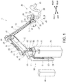
- Fig. 1 is a perspective view illustrating the remote control device 1 according to this embodiment.
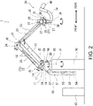
- Fig. 2 is a side view illustrating a configuration of the remote control device 1 illustrated in Fig. 1 .
- one example of transmitting the motive power of the motor by using a belt is described.
- the power transmission of the motor configurations other than the belt may also be adopted.
- a base part 10 is fixed to an upper part of a pedestal 70.
- a support link 11 is provided to an upper part of the base part 10.
- the support link 11 can swivel on a rotation shaft J1 in the vertical direction, with respect to the base part 10.
- a base part of a first arm 12 is supported by an upper part of the support link 11.
- the first arm 12 is pivotable around a first pivot shaft J2 in the lateral direction provided to the support link 11.
- a second arm 13 is provided to a tip-end part of the first arm 12.
- the second arm 13 is pivotable around a second pivot shaft J3 in the lateral direction provided to the first arm 12.
- Two drive shafts J4 are provided coaxially in the horizontal direction to a tip-end part of the second arm 13.
- Each drive shaft J4 is provided to a first pulley 20 and a second pulley 21 which are two rotary bodies. At the part of the first pulley 20 and the second pulley 21, the user interface 30 is provided. The details of the first pulley 20, the second pulley 21, and the user interface 30 will be described later.
- the first arm 12 has two connection links 15 which are link members disposed in parallel to each other, and base part sides of the two connection links 15 are connected via a coupling link 14.
- the coupling link 14 is connected to the lower connection link 15 so as to be turnable about the first pivot shaft J2, and is connected to the upper connection link 15 so as to be turnable about a third pivot shaft J5.
- Tip-end parts of the two connection links 15 are connected to the second pivot shaft J3 of the second arm 13, and a fourth pivot shaft J6 provided with a given interval from the second pivot shaft J3.
- the first arm 12 is formed in a parallel link structure including the two connection links 15, the coupling link 14 and a part of the second arm 13, which are connected by the first pivot shaft J2 and the second pivot shaft J3, and the third pivot shaft J5 and the fourth pivot shaft J6, respectively.
- a first motor 22 which makes a force-sense feedback about a pitch axis L1 act on the user interface 30, and a second motor 23 which makes a force-sense feedback about a roll axis L2 act on act on the user interface 30, are disposed on the base part side of the connection links 15, which is the base part side of the first arm 12.
- the weight on the user interface 30 side (including a spherical surface parallel link 31 described later) is reduced, as compared with a case where it is disposed at the user interface 30, to reduce the moment of inertia when the user interface 30 is operated, thereby improving the operability of the user interface 30.
- a middle pulley 24 is provided to the fourth pivot shaft J6.
- the middle pulley 24 has a configuration in which four belts are wound in the axial direction of the fourth pivot shaft J6.
- Two first transmission belts 25 connect between the middle pulley 24 and pulleys (not illustrated) of the first motor 22 and the second motor 23.
- Two second transmission belts 26 connect between the middle pulley 24, and the first pulley 20 and the second pulley 21 which are disposed side by side on the drive shafts J4. Toothed belts may be used as the transmission belts 25 and 26. By using the toothed belts, the rotation phase between the two axes can be maintained accurately.
- the first motor 22 has a sensor which outputs a signal of a rotation angle on the pitch axis L1 ( Fig. 3 ) when the user interface 30 is operated. Further, the second motor 23 has a sensor which outputs a signal of a rotation angle on the roll axis L2 ( Fig. 3 ) when the user interface 30 is operated.
- An encoder can be used as the sensor.
- the first pivot shaft J2 which supports the base part of the first arm 12 is provided with a fourth motor 29.
- the fourth motor 29 makes a force-sense feedback act on the user interface 30 according to the operation of the first arm 12, and has a sensor which outputs a signal of a pivot angle of the first arm 12.
- An encoder can be used as the sensor.
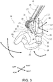
- Fig. 3 is an enlarged perspective view of the user interface 30 of the remote control device 1 illustrated in Fig. 1 , when seen in the opposite direction of Fig. 1 .
- the illustrated user interface 30 is in a state where no external force acts on the user interface 30.
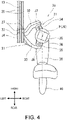
- Fig. 4 is a plan view of the user interface 30 illustrated in Fig. 3 .
- a configuration of the user interface 30 provided to the tip-end part of the second arm 13 is described based on these drawings.
- the tip-end part of the second arm 13 is horizontally provided with the two drive shafts J4, and the first pulley 20 and the second pulley 21 are independently and rotatably supported by the respective drive shafts J4.
- Tension rollers 27 are provided near the first pulley 20 and the second pulley 21 so that the tension of the second transmission belt 26 is maintained.
- a spherical surface parallel link 31 is provided to the side of the second pulley 21 as a link structure.
- the link structure may be other than the spherical surface parallel link 31, as long as it makes the user interface 30 pivotable with respect to the second arm 13 on mutually-perpendicular three axes passing through its center point P.
- Base parts of a first link member 32 and a second link member 33 which are the configuration of the spherical surface parallel link 31 are fixed to the first pulley 20 and the second pulley 21, respectively.
- a first bracket 36 and a second bracket 37 which constitute the spherical surface parallel link 31 are provided on the axis of a rotation shaft J9 perpendicular to the drive shafts J4, and a tip-end part of the first link member 32 is connected to a first support 34 of the first bracket 36, as a revolute pair.
- a tip-end part of the second link member 33 is connected to a second support 35 of the second bracket 37, as a revolute pair.
- This spherical surface parallel link 31 makes the user interface 30 pivotable, with respect to the second arm 13, on the perpendicular three axes (the pitch axis L1, the roll axis L2, and a yaw axis L3) passing through the center point P of the spherical surface parallel link 31.
- This spherical surface parallel link 31 is provided to the side of the second pulley 21 so that the center point P is located on the axes of the two drive shafts J4.
- the centers of curvature of the first link member 32 and the second link member 33 formed in an arc shape are in agreement with each other at the center point P on the axis of the drive shafts J4.
- rotation shafts J7 and J8 of the first support 34 and the second support 35 which are connected as a revolute pair at the tip ends, are also in agreement with each other at the center point P.
- a base part of the first link member 32 is fixed to a side surface of the first pulley 20, and a base end of the second link member 33 is fixed to a side surface of the second pulley 21. Therefore, the first link member 32 and the second link member 33 of the spherical surface parallel link 31 rotate centering on the center point P.
- the user interface 30 is attached to the second bracket 37 on the axis of the rotation shaft J9 passing through the center point P of the spherical surface parallel link 31.
- the user interface 30 has a rotary part 38 extending downwardly from the second bracket 37, an offset arm 39 extending from the rotary part 38 so as to be curved rearward which intersects with the axis of the drive shaft L4, and a grip 40 provided to an end of the offset arm 39.
- a base part of the offset arm 39 is attached to the second bracket 37 of the spherical surface parallel link 31 so that the grip 40 of the user interface 30 extends in the direction which intersects with the rotation shaft J9 from the side of the second pulley 21.
- a third motor 28 which makes a force-sense feedback about the yaw axis L3 act on the user interface 30 is provided to an upper surface of the first bracket 36.
- the third motor 28 has a sensor which outputs a signal of a rotation angle when rotating the grip 40 horizontally (a rotation angle of the rotary part 38).
- the grip 40 by moving the grip 40 in the front and rear, and left and right directions as illustrated by arrows, using the spherical surface parallel link 31 where the first link member 32 and the second link member 33 are fixed to the two pulleys 20 and 21, respectively, the two pulleys 20 and 21 can be rotated in the same direction or the opposite directions, as will be described later.
- the grip 40 by moving the grip 40, the second arm 13 can change the angle at the drive shaft J4 and the second pivot shaft J3, and the first arm 12 can change the pivot angle at the first pivot shaft J2.
- the support link 11 can be swiveled on the rotation shaft J1, together with the second arm 13 and the first arm 12.
- the variations of the rotation angles on the pitch axis L1, the roll axis L2, and the yaw axis L3 when the user interface 30 is operated are detected by the first motor 22, the second motor 23, and the third motor 28, respectively.
- An electric signal acquired by operating the grip 40 of the user interface 30 is outputted to a corresponding action part of the robot as an electric signal according to the bilateral control via a control device 60 ( Figs. 1 and 2 ).
- the electric signal acquired by an external force received by the action part of the robot is outputted to each of the motors 22, 23, and 28 which give the force-sense feedbacks to the user interface 30 as the electric signal according to the bilateral control.
- the control device 60 has a processor, a volatile memory, a nonvolatile memory, an I/O interface, etc.
- the control device 60 outputs the electric signal according to the bilateral control based on the inputted electric signal.
- the outputted electric signal is obtained by the processor carrying out a calculation using the volatile memory based on a program stored in the nonvolatile memory so that it becomes a signal according to the bilateral control with respect to the inputted electric signal.
- the first motor 22 which makes the force-sense feedback about the pitch axis L1 act on the user interface 30, and the second motor 23 which makes the force-sense feedback about the roll axis L2 act on the user interface 30 are provided to the base part side of the first arm 12.
- the weight on the user interface 30 side can be reduced by disposing the first motor 22 and the second motor 23 which are heavy objects on the base part side of the first arm 12 which is away from the user interface 30, thereby improving the operability of the user interface 30.
- the remote control device 1 of this embodiment by supporting the user interface 30 provided to the tip-end part of the second arm 13 by the spherical surface parallel link 31 which is not provided in the tip-end direction which is the extending direction of the second arm 13, but provided to the side, the distance from the tip-end part of the second arm 13 to the grip 40 can be shortened, and a large operating range of the user interface 30 can be secured, while forming the user interface 30 compactly. That is, according to the remote control device 1 of this embodiment, the user interface 30 is supported by the spherical surface parallel link 31 provided to the side of the second pulley 21 so that the grip 40 is offset from the first pulley 20 and the second pulley 21 by a given distance. Therefore, the configuration around the grip 40 can be made compact, and the operability can be improved with an expanded operating range where the operation about the yaw axis L3 for operating a wrist part of the robot is about 180° rightward and about 90° leftward.
- the user interface 30 of this embodiment is provided with the grip 40 so that it is operated with a single hand, but the user interface 30 is not limited to this embodiment and it may be configured to be operated with both hands.
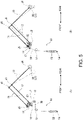
- Figs. 5(A) and 5(B) are structural charts schematically illustrating a self-weight compensator 50 of the remote control device 1 illustrated in Fig. 2 .
- the self-weight compensator 50 is a configuration for balancing the weight.
- the entire configuration of the self-weight compensator 50 is described based on Fig. 2 , and it is concretely described based on Figs. 5(A) and 5(B) . Note that, in Figs. 5(A) and 5(B) , only the configuration of each self-weight compensator is illustrated.
- the remote control device 1 of this embodiment is provided with the self-weight compensator 50 which extends in the up-and-down direction along the pedestal 70.
- the self-weight compensator 50 is provided at the opposite direction from the extending direction of the first arm 12 with respect to the support link 11.
- the self-weight compensator 50 has a pair of frame members 51 provided to the support link 11, and a first coil spring 52 and a second coil spring 53 which are spring members provided between the pair of frame members 51.
- the frame members 51 are a pair of plate members which are fixed at upper end parts to the support link 11, and extend downwardly along the pedestal 70.
- the first coil spring 52 and the second coil spring 53 are supported at lower end parts by a spring support shaft 54 which is fixed between the frame members 51, and are connected at upper end parts to a first wire 55 and a second wire 56, respectively.
- the first wire 55 and the second wire 56 are wound around two first rollers 57 provided to upper parts of the frame members 51, and ends of the wires then extend toward the base part of the first arm 12.
- the first wire 55 connected to the upper end part of the first coil spring 52 is wound around the first roller 57, and then extends rearward of the support link 11. Further, it is wound around a second roller 58 provided to a rear part of the support link 11 and extends forward, and is connected to a first connecting member 16 provided to a front part of the coupling link 14.
- the first coil spring 52 and the first wire 55 use a spring force of the first coil spring 52 to compensate the self-weight in a direction of an arrow R1 which acts around the first pivot shaft J2, when the second arm 13 inclines to the first arm 12, as illustrated by two-dot chain lines.
- the second wire 56 connected to the upper end part of the second coil spring 53 is wound around the first roller 57, and is then connected to a second connecting member 17 provided forward centering on the first pivot shaft J2 so that it pivots integrally with the first arm 12.
- the second coil spring 53 and the second wire 56 use a spring force of the second coil spring 53 to compensate the self-weight in a direction of an arrow R2 which acts around the first pivot shaft J2, when the first arm 12 and the second arm 13 incline, as illustrated by two-dot chain lines.
- the self-weight compensator 50 is in a state where the self-weight compensation by the first coil spring 52 and the second coil spring 53 always works, and therefore, the self-weight compensation is appropriately carried out according to the inclination of each of the first arm 12 and the second arm 13.
- the first coil spring 52 and the second coil spring 53 are disposed so as to extend along the pedestal 70 so that the spring force of each of the coil springs 52 and 53 is used as a force according to the weight acting on the spring and a distance from the first pivot shaft J2.
- the first arm 12 and the second arm 13 can be maintained in the state illustrated in Fig. 2 when no external force acts on the user interface 30. Further, since such a self-weight compensator 50 is disposed so as to extend in the up-and-down direction along the pedestal 70 on the opposite side of the extending directions of the first arm 12 and the second arm 13, the turning radius and the moment of inertia can be reduced, and the grip 40 of the user interface 30 can be operate lightly.
- the coil spring is used as the configuration of the self-weight compensator 50 for compensating the self-weight of the arm
- the configuration for compensating the self-weight may also use a hydraulic damper etc.
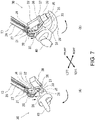
- Figs. 6(A) and 6(B) are views illustrating a state where the user interface 30 illustrated in Fig. 3 is leaned in the front-and-rear direction, where Fig. 6(A) is a perspective view of a state where it is leaned forward, and Fig. 6(B) is a perspective view of a state where it is leaned rearward.
- Figs. 7(A) and 7(B) are views illustrating a state where the user interface 30 illustrated in Fig. 3 is leaned in the left-and-right direction, where Fig. 7(A) is a perspective view of a state where it is leaned leftward, and Fig. 7(B) is a perspective view of a state where it is leaned rightward.
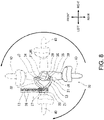
- Fig. 8 is a plan view illustrating a state where the user interface 30 illustrated in Fig. 3 is rotated horizontally.
- a case where the wrist part of the robot (not illustrated) is operated is described as an example.
- the operation of rotating the grip 40 of the user interface 30 in the front-and-rear direction can be performed with a large rotation angle, without contacting the second pulley 21, the first pulley 20, etc. Therefore, also at the wrist part of the robot, the front part can be operated greatly in the up-and-down direction.
- the force received by the wrist part of the robot according to this operation is force-sense fed back to the first pulley 20 and the second pulley 21 via the transmission belts 25 and 26 and the middle pulley 24 by the first motor 22 and the second motor 23 which are provided to the base part side of the connection link 15, as the forces in the same direction.
- This force-sense feedback is transmitted to the user interface 30 via the spherical surface parallel link 31 coupled to the first pulley 20 and the second pulley 21.
- the force received by the wrist part of the robot according to this operation is force-sense fed back to the first pulley 20 and the second pulley 21 via the transmission belts 25 and 26 and the middle pulley 24 by the first motor 22 and the second motor 23 provided to the base part side of the connection link 15 (the base part side of the first arm 12) as a force in the direction of reaction force.
- This force-sense feedback is transmitted to the user interface 30 via the spherical surface parallel link 31 coupled to the first pulley 20 and the second pulley 21.
- the force received by the wrist part of the robot according to this operation is force-sense fed back to the first pulley 20 and the second pulley 21 by the first motor 22 and the second motor 23 which are provided on the base part side of the connection link 15 (the base part side of the first arm 12) as the force in the direction of reaction force.
- This force-sense feedback is transmitted to the user interface 30 via the spherical surface parallel link 31 coupled to the first pulley 20 and the second pulley 21.
- the grip 40 of the user interface 30 when the grip 40 of the user interface 30 is horizontally rotated to the right, the user interface 30 can be rotated rightward centering on the rotary part 38 ( Fig. 3 ) provided on the axis of the rotation shaft J9. Further, when the grip 40 of the user interface 30 is horizontally rotated to the left, the user interface 30 can be rotated leftward centering on the rotary part 38 ( Fig. 3 ) provided on the axis of the rotation shaft J9.
- the rotation of the grip 40 to the right can be made in a large range of about 180°.
- the rotation of the grip 40 to the left can be made in a large range of about 90°, without contacting the pulleys 20 and 21.
- the wrist part of the robot can appropriately be rotated in the horizontal direction.
- the force received by the wrist part of the robot according to this operation is force-sense fed back to the user interface 30 by the third motor 28 provided to the first bracket 36 of the spherical surface parallel link 31 as the force in the direction of reaction force.
- the first motor 22 and the second motor 23 which make the force-sense feedbacks in the direction of the pitch axis L1 and the direction of the roll axis L2 act on the user interface 30 are provided to the base part side of the first arm 12 (the base part side of the connection link 15). Therefore, while suppressing the increase in the weight of the user interface 30, the weight on the user interface 30 side of the first arm 12 and the second arm 13 which pivot at the base part side of the first arm 12 as the fulcrum can be reduced. Moreover, since the first arm 12 and the second arm 13 can be maintained at a given angle by the self-weight compensator 50, the state of the user interface 30 can be maintained. Therefore, the burden of controlling while holding the grip 40 of the user interface 30 can be reduced, and operator's burden can be reduced even if it is a long period operation.
- the actuators which make the force-sense feedbacks act on the user interface 30 are the motors 22, 23, and 28, they are not limited to the above embodiment, and the actuators may be other than the motors 22, 23, and 28.
- the remote control device 1 described above can remotely control, for example, an articulated robot which performs a slag scraping work, and civil engineering machinery which scoops earth and sand, etc. Since the slag scraping work is a work, in the process of manufacturing a cast product, for taking out and removing slag (impurities, such as slag and oxide) from a molten metal surface of molten metal material, the hard work at high temperature is required, thus, the work by a robot is considered. According to the remote control device 1 described above, such a slag scraping work can also be remotely controlled by operating the user interface 30 with the expanded operating range at a location distant from the robot. In addition, since the configuration around the user interface 30 is compact, the long-period work can also be performed appropriately.
- slag scraping work is a work, in the process of manufacturing a cast product, for taking out and removing slag (impurities, such as slag and oxide) from a molten metal surface of molten metal
- the remote control device 1 described above can also be used in a case where a worker cannot directly control the civil engineering machinery, such as a shovel vehicle, and it can operate the user interface 30 in the expanded operating range to remotely control a scooping work of earth and sand etc. Note that the application of the remote control device 1 is not limited to those described above.
- the link structure may include the spherical surface parallel link. According to such a configuration, the user interface can easily be turnable about the three axes of the pitch axis, the roll axis, and the yaw axis, which pass through the center point.
- the spherical surface parallel link may include the first link member and the second link member which rotate centering on the center point, the brackets including the first support and the second support which are connected to the tip ends of the first link member and the second link member, respectively, as a revolute pair.
- the base ends of the first link member and the second link member may be fixed to the two rotary bodies, respectively. According to such a configuration, by the spherical surface parallel link including the first link member and the second link member which are fixed to the two rotary bodies, respectively, the two rotary bodies can appropriately be rotated in the same direction or the opposite directions with the operation of the user interface.
- first arm may be supported by the support link that is disposed to the base part so as to be turnable about the rotation shaft, and the second arm may be connected to the tip-end part of the first arm via the pivot shaft disposed in parallel to the drive shafts.
- the pivot shaft disposed in parallel to the drive shafts the second arm can appropriately be turned with respect to the first arm, with the operation of the user interface.
- the first arm may have the two link members disposed in parallel.
- the actuators for exerting, on the user interface, force-sense feedbacks about the pitch axis, the roll axis, and the yaw axis may be provided.
- the actuators which exert, on the user interface, the force-sense feedbacks about the pitch axis and the roll axis via the rotary body may be disposed at the base part side of the first arm. According to such a configuration, the actuators which are heavy objects are disposed at the base part side of the first arm, and the weight of the tip-end side of the first arm, the part of the second arm, and the user interface can be reduced, thereby improving the operability of the user interface.
- the rotary body may include a pulley
- the middle pulley may be disposed at the tip-end part of the first arm
- the transmission belts may connect between the actuator and the middle pulley, and between the middle pulley and the pulleys.
- the actuator which gives the force-sense feedback about the yaw axis may be included in the link structure.
- the actuator which exerts, on the user interface, the force-sense feedback about the yaw axis can be included in the link structure, and thus, the force-sense feedback can be exerted appropriately.
- the pedestal which fixes the base part may be provided, and the self-weight compensator which compensates the self-weights of the first arm and the second arm may be provided along the pedestal.
- the self-weight compensator which compensates the self-weight of the first arm which extends from the base part and the self-weight of the second arm may have a small turning radius along the pedestal, and therefore, the moment of inertia can be reduced, and the operability of the user interface can be improved.
- the self-weight compensator may include the spring member disposed so as to extend along the pedestal. According to such a configuration, the self-weight compensation of the first arm and the second arm can appropriately be performed by the spring member with the simple structure.
Landscapes
- Engineering & Computer Science (AREA)
- Robotics (AREA)
- Mechanical Engineering (AREA)
- Human Computer Interaction (AREA)
- Manipulator (AREA)
- Health & Medical Sciences (AREA)
- General Health & Medical Sciences (AREA)
- Orthopedic Medicine & Surgery (AREA)
Abstract
Description
- The present disclosure relates to a remote control device for a remote control of an articulated robot etc.
- Conventionally, a robot or machinery, which is used in a place where people are difficult to enter etc., may be remotely controlled. Although there are various types of control devices for remotely controlling the robot or machinery, recently, some control devices carry out a force-sense control of the control device (master) and the robot (slave) using a bilateral method. Hereinafter, "the force-sense control by the bilateral method" may also be referred to as "the bilateral control."
- The control device which performs the bilateral control needs to carry out a force-sense feedback of a kinesthetic sense which acts on the robot or machinery to a user, and there are some control devices provided with a plurality of actuators. Some control devices use motors as the actuators.
- As this kind of conventional art, for example, there is a remote control device in which a user can perform the control while placing his/her elbows with his/her wrists so that he/she does not get tired even if he/she uses the device for a long period of time (for example, see Patent Document 1). With this remote control device, the user can perform the remote control by holding interface parts (grips) and tilting coupling members coupled to armrest members, and the force-sense feedback to the user is performed by motors provided inside the coupling members.
- Further, as another conventional art, a manipulator drive unit which operates a manipulator is fixed to a bracket of a spherical surface parallel link, and the spherical surface parallel link is driven by a link drive unit (for example, see Patent Document 2). In this conventional art, the remote center at which the manipulator is operated is acquired by the link drive unit of the spherical surface parallel link.
-
- [Patent Document 1]
JP2013-088852A - [Patent Document 2]
JP2017-064892A - However, since
Patent Document 1 described above is the remote control device which is operated while the operator places the elbows including the wrists, the structure will be complicated if the operating range of the user interface is expanded to expand the operating range of the robot. In addition, since the places at which the operator puts the elbows are limited, the robot and machinery to be remotely controlled are limited. - Further, in Patent Document 2 described above, although the remote center for driving the manipulator can be acquired by the link drive unit of the spherical surface parallel link, the operating range of the user interface cannot be expanded, thereby limiting the robot and machinery to be remotely controlled. In addition, it is difficult to provide the configuration for making the force-sense feedback in the case of performing the bilateral control act on the user interface.
- Thus, one purpose of the present disclosure is to provide a remote control device, capable of reducing the size of a configuration around a user interface, and obtaining the expanded operating range.
- In order to achieve the purpose, the present disclosure includes a first arm supported by a base part, a second arm connected to a tip-end part of the first arm, two rotary bodies disposed side by side at a tip-end part of the second arm, a link structure in which link members are fixed to the two rotary bodies, respectively, and a user interface attached to the link structure. The two rotary bodies are independently and rotatably supported by respective coaxial drive shafts disposed horizontally. The user interface is pivotable with respect to the second arm on each of mutually-perpendicular three axes passing through a center point of the link structure. The link structure is disposed at the lateral side of the rotary bodies so that the center point is located on an axis of the two drive shafts. The user interface is attached to the link structure on an axis of a rotation shaft passing through the center point. The "link structure" in the documents of the present specification and the claims refers to one including the plurality of link members each of which moves independently with respect to the center point of the three axes. The three axes are three axes of a pitch axis, a roll axis, and a yaw axis.
- According to this configuration, since the user interface is attached to the link structure which is disposed at the lateral side of the two rotary bodies disposed side by side at the tip-end part of the second arm and on the axis of the drive shafts of the rotary bodies, the user interface can be operated within a large operating range. In addition, since the user interface is disposed at the link structure disposed at the lateral side of the rotary bodies, the size of the configuration around the user interface can be reduced.
- According to the present disclosure, a remote control device which is capable of reducing the size of a configuration around a user interface, and obtaining the expanded operating range, can be provided.
-
-
Fig. 1 is a perspective view illustrating a remote control device according to one embodiment of the present disclosure. -
Fig. 2 is a side view of the remote control device illustrated inFig. 1 . -
Fig. 3 is an enlarged perspective view illustrating a part of a user interface of the remote control device illustrated inFig. 1 , when seen in the opposite direction ofFig. 1 . -
Fig. 4 is a plan view of the part of the user interface illustrated inFig. 3 . -
Figs. 5(A) and 5(B) are structural charts schematically illustrating a self-weight compensator of the remote control device illustrated inFig. 2 . -
Figs. 6(A) and 6(B) are views illustrating a state where the user interface illustrated inFig. 3 is leaned in the front-and-rear direction, whereFig. 6(A) is a perspective view of a state where it is leaned forward, andFig. 6(B) is a perspective view of a state where it is leaned rearward. -
Figs. 7(A) and 7(B) are views illustrating a state where the user interface illustrated inFig. 3 is leaned in the left-and-right direction, whereFig. 7(A) is a perspective view of a state where it is leaned leftward, andFig. 7(B) is a perspective view of a state where it is leaned rightward. -
Fig. 8 is a plan view illustrating a state where the user interface illustrated inFig. 3 is rotated horizontally. - Hereinafter, one embodiment is described based on the drawings. In the following embodiment, a
remote control device 1 in which auser interface 30 is operated with a single hand is described as an example. Further, in the following description, a case where an articulated robot (not illustrated) is remotely controlled by theremote control device 1 is described as an example. Theremote control device 1 and the articulated robot (hereinafter, simply referred to as "the robot") are force-sense controlled by a bilateral method (bilaterally controlled). Since the bilateral control can utilize a known method, detailed description thereof is omitted. Further, in this embodiment, a motor (for example, a servomotor) as an actuator which makes a force-sense feedback act on theuser interface 30 is described as an example. The concept of front and rear, and left and right directions in the documents of the present specification and the claims is in agreement with the concept of front and rear, and left and right directions illustrated inFig. 1 . -
Fig. 1 is a perspective view illustrating theremote control device 1 according to this embodiment.Fig. 2 is a side view illustrating a configuration of theremote control device 1 illustrated inFig. 1 . In the following embodiment, one example of transmitting the motive power of the motor by using a belt is described. As for the power transmission of the motor, configurations other than the belt may also be adopted. - In the
remote control device 1 of this embodiment, abase part 10 is fixed to an upper part of apedestal 70. Asupport link 11 is provided to an upper part of thebase part 10. Thesupport link 11 can swivel on a rotation shaft J1 in the vertical direction, with respect to thebase part 10. A base part of afirst arm 12 is supported by an upper part of thesupport link 11. Thefirst arm 12 is pivotable around a first pivot shaft J2 in the lateral direction provided to thesupport link 11. Asecond arm 13 is provided to a tip-end part of thefirst arm 12. Thesecond arm 13 is pivotable around a second pivot shaft J3 in the lateral direction provided to thefirst arm 12. Two drive shafts J4 are provided coaxially in the horizontal direction to a tip-end part of thesecond arm 13. Each drive shaft J4 is provided to afirst pulley 20 and asecond pulley 21 which are two rotary bodies. At the part of thefirst pulley 20 and thesecond pulley 21, theuser interface 30 is provided. The details of thefirst pulley 20, thesecond pulley 21, and theuser interface 30 will be described later. - Further, the
first arm 12 has twoconnection links 15 which are link members disposed in parallel to each other, and base part sides of the twoconnection links 15 are connected via acoupling link 14. Thecoupling link 14 is connected to thelower connection link 15 so as to be turnable about the first pivot shaft J2, and is connected to theupper connection link 15 so as to be turnable about a third pivot shaft J5. Tip-end parts of the twoconnection links 15 are connected to the second pivot shaft J3 of thesecond arm 13, and a fourth pivot shaft J6 provided with a given interval from the second pivot shaft J3. Thefirst arm 12 is formed in a parallel link structure including the twoconnection links 15, thecoupling link 14 and a part of thesecond arm 13, which are connected by the first pivot shaft J2 and the second pivot shaft J3, and the third pivot shaft J5 and the fourth pivot shaft J6, respectively. - As will be described later, a
first motor 22 which makes a force-sense feedback about a pitch axis L1 act on theuser interface 30, and asecond motor 23 which makes a force-sense feedback about a roll axis L2 act on act on theuser interface 30, are disposed on the base part side of the connection links 15, which is the base part side of thefirst arm 12. By disposing the two motors (thefirst motor 22 and the second motor 23) on the base part side of thefirst arm 12, the weight on theuser interface 30 side (including a spherical surfaceparallel link 31 described later) is reduced, as compared with a case where it is disposed at theuser interface 30, to reduce the moment of inertia when theuser interface 30 is operated, thereby improving the operability of theuser interface 30. - A
middle pulley 24 is provided to the fourth pivot shaft J6. Themiddle pulley 24 has a configuration in which four belts are wound in the axial direction of the fourth pivot shaft J6. Twofirst transmission belts 25 connect between themiddle pulley 24 and pulleys (not illustrated) of thefirst motor 22 and thesecond motor 23. Twosecond transmission belts 26 connect between themiddle pulley 24, and thefirst pulley 20 and thesecond pulley 21 which are disposed side by side on the drive shafts J4. Toothed belts may be used as thetransmission belts first motor 22 has a sensor which outputs a signal of a rotation angle on the pitch axis L1 (Fig. 3 ) when theuser interface 30 is operated. Further, thesecond motor 23 has a sensor which outputs a signal of a rotation angle on the roll axis L2 (Fig. 3 ) when theuser interface 30 is operated. An encoder can be used as the sensor. - The first pivot shaft J2 which supports the base part of the
first arm 12 is provided with afourth motor 29. Thefourth motor 29 makes a force-sense feedback act on theuser interface 30 according to the operation of thefirst arm 12, and has a sensor which outputs a signal of a pivot angle of thefirst arm 12. An encoder can be used as the sensor. -
Fig. 3 is an enlarged perspective view of theuser interface 30 of theremote control device 1 illustrated inFig. 1 , when seen in the opposite direction ofFig. 1 . The illustrateduser interface 30 is in a state where no external force acts on theuser interface 30.Fig. 4 is a plan view of theuser interface 30 illustrated inFig. 3 . A configuration of theuser interface 30 provided to the tip-end part of thesecond arm 13 is described based on these drawings. - The tip-end part of the
second arm 13 is horizontally provided with the two drive shafts J4, and thefirst pulley 20 and thesecond pulley 21 are independently and rotatably supported by the respective drive shafts J4.Tension rollers 27 are provided near thefirst pulley 20 and thesecond pulley 21 so that the tension of thesecond transmission belt 26 is maintained. - Moreover, in this embodiment, a spherical surface
parallel link 31 is provided to the side of thesecond pulley 21 as a link structure. The link structure may be other than the spherical surfaceparallel link 31, as long as it makes theuser interface 30 pivotable with respect to thesecond arm 13 on mutually-perpendicular three axes passing through its center point P. Base parts of afirst link member 32 and asecond link member 33 which are the configuration of the spherical surfaceparallel link 31 are fixed to thefirst pulley 20 and thesecond pulley 21, respectively. On the other hand, afirst bracket 36 and asecond bracket 37 which constitute the spherical surfaceparallel link 31 are provided on the axis of a rotation shaft J9 perpendicular to the drive shafts J4, and a tip-end part of thefirst link member 32 is connected to afirst support 34 of thefirst bracket 36, as a revolute pair. A tip-end part of thesecond link member 33 is connected to asecond support 35 of thesecond bracket 37, as a revolute pair. This spherical surfaceparallel link 31 makes theuser interface 30 pivotable, with respect to thesecond arm 13, on the perpendicular three axes (the pitch axis L1, the roll axis L2, and a yaw axis L3) passing through the center point P of the spherical surfaceparallel link 31. This spherical surfaceparallel link 31 is provided to the side of thesecond pulley 21 so that the center point P is located on the axes of the two drive shafts J4. - As illustrated in
Fig. 4 , in the spherical surfaceparallel link 31 of this embodiment, the centers of curvature of thefirst link member 32 and thesecond link member 33 formed in an arc shape are in agreement with each other at the center point P on the axis of the drive shafts J4. As for thefirst link member 32 and thesecond link member 33 which rotate centering on the center point P, rotation shafts J7 and J8 of thefirst support 34 and thesecond support 35, which are connected as a revolute pair at the tip ends, are also in agreement with each other at the center point P. A base part of thefirst link member 32 is fixed to a side surface of thefirst pulley 20, and a base end of thesecond link member 33 is fixed to a side surface of thesecond pulley 21. Therefore, thefirst link member 32 and thesecond link member 33 of the spherical surfaceparallel link 31 rotate centering on the center point P. - The
user interface 30 is attached to thesecond bracket 37 on the axis of the rotation shaft J9 passing through the center point P of the spherical surfaceparallel link 31. Theuser interface 30 has arotary part 38 extending downwardly from thesecond bracket 37, an offsetarm 39 extending from therotary part 38 so as to be curved rearward which intersects with the axis of the drive shaft L4, and agrip 40 provided to an end of the offsetarm 39. Thus, a base part of the offsetarm 39 is attached to thesecond bracket 37 of the spherical surfaceparallel link 31 so that thegrip 40 of theuser interface 30 extends in the direction which intersects with the rotation shaft J9 from the side of thesecond pulley 21. - A
third motor 28 which makes a force-sense feedback about the yaw axis L3 act on theuser interface 30 is provided to an upper surface of thefirst bracket 36. Thethird motor 28 has a sensor which outputs a signal of a rotation angle when rotating thegrip 40 horizontally (a rotation angle of the rotary part 38). - According to such a
user interface 30, by moving thegrip 40 in the front and rear, and left and right directions as illustrated by arrows, using the spherical surfaceparallel link 31 where thefirst link member 32 and thesecond link member 33 are fixed to the twopulleys pulleys grip 40, thesecond arm 13 can change the angle at the drive shaft J4 and the second pivot shaft J3, and thefirst arm 12 can change the pivot angle at the first pivot shaft J2. Moreover, by moving thegrip 40, thesupport link 11 can be swiveled on the rotation shaft J1, together with thesecond arm 13 and thefirst arm 12. - According to this
remote control device 1, the variations of the rotation angles on the pitch axis L1, the roll axis L2, and the yaw axis L3 when theuser interface 30 is operated (including inclination and rotation) are detected by thefirst motor 22, thesecond motor 23, and thethird motor 28, respectively. An electric signal acquired by operating thegrip 40 of theuser interface 30 is outputted to a corresponding action part of the robot as an electric signal according to the bilateral control via a control device 60 (Figs. 1 and2 ). On the other hand, the electric signal acquired by an external force received by the action part of the robot is outputted to each of themotors user interface 30 as the electric signal according to the bilateral control. Thecontrol device 60 has a processor, a volatile memory, a nonvolatile memory, an I/O interface, etc. Thecontrol device 60 outputs the electric signal according to the bilateral control based on the inputted electric signal. The outputted electric signal is obtained by the processor carrying out a calculation using the volatile memory based on a program stored in the nonvolatile memory so that it becomes a signal according to the bilateral control with respect to the inputted electric signal. - In addition, according to the
remote control device 1 of this embodiment, thefirst motor 22 which makes the force-sense feedback about the pitch axis L1 act on theuser interface 30, and thesecond motor 23 which makes the force-sense feedback about the roll axis L2 act on theuser interface 30 are provided to the base part side of thefirst arm 12. Thus, the weight on theuser interface 30 side can be reduced by disposing thefirst motor 22 and thesecond motor 23 which are heavy objects on the base part side of thefirst arm 12 which is away from theuser interface 30, thereby improving the operability of theuser interface 30. - In addition, according to the
remote control device 1 of this embodiment, by supporting theuser interface 30 provided to the tip-end part of thesecond arm 13 by the spherical surfaceparallel link 31 which is not provided in the tip-end direction which is the extending direction of thesecond arm 13, but provided to the side, the distance from the tip-end part of thesecond arm 13 to thegrip 40 can be shortened, and a large operating range of theuser interface 30 can be secured, while forming theuser interface 30 compactly. That is, according to theremote control device 1 of this embodiment, theuser interface 30 is supported by the spherical surfaceparallel link 31 provided to the side of thesecond pulley 21 so that thegrip 40 is offset from thefirst pulley 20 and thesecond pulley 21 by a given distance. Therefore, the configuration around thegrip 40 can be made compact, and the operability can be improved with an expanded operating range where the operation about the yaw axis L3 for operating a wrist part of the robot is about 180° rightward and about 90° leftward. - Note that the
user interface 30 of this embodiment is provided with thegrip 40 so that it is operated with a single hand, but theuser interface 30 is not limited to this embodiment and it may be configured to be operated with both hands. -
Figs. 5(A) and 5(B) are structural charts schematically illustrating a self-weight compensator 50 of theremote control device 1 illustrated inFig. 2 . The self-weight compensator 50 is a configuration for balancing the weight. The entire configuration of the self-weight compensator 50 is described based onFig. 2 , and it is concretely described based onFigs. 5(A) and 5(B) . Note that, inFigs. 5(A) and 5(B) , only the configuration of each self-weight compensator is illustrated. - As illustrated in
Fig. 2 , theremote control device 1 of this embodiment is provided with the self-weight compensator 50 which extends in the up-and-down direction along thepedestal 70. The self-weight compensator 50 is provided at the opposite direction from the extending direction of thefirst arm 12 with respect to thesupport link 11. The self-weight compensator 50 has a pair offrame members 51 provided to thesupport link 11, and afirst coil spring 52 and asecond coil spring 53 which are spring members provided between the pair offrame members 51. Theframe members 51 are a pair of plate members which are fixed at upper end parts to thesupport link 11, and extend downwardly along thepedestal 70. Thefirst coil spring 52 and thesecond coil spring 53 are supported at lower end parts by aspring support shaft 54 which is fixed between theframe members 51, and are connected at upper end parts to afirst wire 55 and asecond wire 56, respectively. Thefirst wire 55 and thesecond wire 56 are wound around twofirst rollers 57 provided to upper parts of theframe members 51, and ends of the wires then extend toward the base part of thefirst arm 12. - As illustrated in
Fig. 5(A) , thefirst wire 55 connected to the upper end part of thefirst coil spring 52 is wound around thefirst roller 57, and then extends rearward of thesupport link 11. Further, it is wound around asecond roller 58 provided to a rear part of thesupport link 11 and extends forward, and is connected to a first connectingmember 16 provided to a front part of thecoupling link 14. Thefirst coil spring 52 and thefirst wire 55 use a spring force of thefirst coil spring 52 to compensate the self-weight in a direction of an arrow R1 which acts around the first pivot shaft J2, when thesecond arm 13 inclines to thefirst arm 12, as illustrated by two-dot chain lines. - As illustrated in
Fig. 5(B) , thesecond wire 56 connected to the upper end part of thesecond coil spring 53 is wound around thefirst roller 57, and is then connected to a second connectingmember 17 provided forward centering on the first pivot shaft J2 so that it pivots integrally with thefirst arm 12. Thesecond coil spring 53 and thesecond wire 56 use a spring force of thesecond coil spring 53 to compensate the self-weight in a direction of an arrow R2 which acts around the first pivot shaft J2, when thefirst arm 12 and thesecond arm 13 incline, as illustrated by two-dot chain lines. The self-weight compensator 50 is in a state where the self-weight compensation by thefirst coil spring 52 and thesecond coil spring 53 always works, and therefore, the self-weight compensation is appropriately carried out according to the inclination of each of thefirst arm 12 and thesecond arm 13. - In this self-
weight compensator 50, thefirst coil spring 52 and thesecond coil spring 53 are disposed so as to extend along thepedestal 70 so that the spring force of each of the coil springs 52 and 53 is used as a force according to the weight acting on the spring and a distance from the first pivot shaft J2. - According to such a self-
weight compensator 50, thefirst arm 12 and thesecond arm 13 can be maintained in the state illustrated inFig. 2 when no external force acts on theuser interface 30. Further, since such a self-weight compensator 50 is disposed so as to extend in the up-and-down direction along thepedestal 70 on the opposite side of the extending directions of thefirst arm 12 and thesecond arm 13, the turning radius and the moment of inertia can be reduced, and thegrip 40 of theuser interface 30 can be operate lightly. - Although in this embodiment the coil spring is used as the configuration of the self-
weight compensator 50 for compensating the self-weight of the arm, the configuration for compensating the self-weight may also use a hydraulic damper etc. -
Figs. 6(A) and 6(B) are views illustrating a state where theuser interface 30 illustrated inFig. 3 is leaned in the front-and-rear direction, whereFig. 6(A) is a perspective view of a state where it is leaned forward, andFig. 6(B) is a perspective view of a state where it is leaned rearward.Figs. 7(A) and 7(B) are views illustrating a state where theuser interface 30 illustrated inFig. 3 is leaned in the left-and-right direction, whereFig. 7(A) is a perspective view of a state where it is leaned leftward, andFig. 7(B) is a perspective view of a state where it is leaned rightward.Fig. 8 is a plan view illustrating a state where theuser interface 30 illustrated inFig. 3 is rotated horizontally. In the following example, a case where the wrist part of the robot (not illustrated) is operated is described as an example. - As illustrated in
Fig. 6(A) , when thegrip 40 of theuser interface 30 is leaned forward, the rear parts of thefirst pulley 20 and thesecond pulley 21 are rotated downwardly by the same angle, together with thefirst bracket 36 and thesecond bracket 37 of the spherical surfaceparallel link 31. Therefore, the wrist part of the robot which is remotely controlled can be leaned so that the front part rotates upwardly. - On the other hand, as illustrated in
Fig. 6(B) , when thegrip 40 of theuser interface 30 is leaned rearward, the rear parts of thefirst pulley 20 and thesecond pulley 21 are rotated upwardly by the same angle, together with thefirst bracket 36 and thesecond bracket 37 of the spherical surfaceparallel link 31. Therefore, the wrist part of the robot which is remotely controlled can be leaned so that the front parts rotate downwardly. - Since the
user interface 30 is provided to the side of thesecond pulley 21 by the spherical surfaceparallel link 31, the operation of rotating thegrip 40 of theuser interface 30 in the front-and-rear direction can be performed with a large rotation angle, without contacting thesecond pulley 21, thefirst pulley 20, etc. Therefore, also at the wrist part of the robot, the front part can be operated greatly in the up-and-down direction. - Further, the force received by the wrist part of the robot according to this operation is force-sense fed back to the
first pulley 20 and thesecond pulley 21 via thetransmission belts middle pulley 24 by thefirst motor 22 and thesecond motor 23 which are provided to the base part side of theconnection link 15, as the forces in the same direction. This force-sense feedback is transmitted to theuser interface 30 via the spherical surfaceparallel link 31 coupled to thefirst pulley 20 and thesecond pulley 21. - As illustrated in
Fig. 7(A) , when thegrip 40 of theuser interface 30 is leaned leftward, the rotation shaft J8 of thefirst link member 32 and thefirst support 34 of the spherical surfaceparallel link 31 moves upward, and the base part of thefirst link member 32 moves upward to rotate the rear part of thesecond pulley 21 upward. On the other hand, the rotation shaft J7 (Fig. 4 ) of thesecond link member 33 and thesecond support 35 of the spherical surfaceparallel link 31 moves downwardly, and the base part of thesecond link member 33 moves downward to rotate the rear part of thefirst pulley 20 downward. Therefore, the wrist part of the robot which is remotely controlled can be leaned to the left. The force received by the wrist part of the robot according to this operation is force-sense fed back to thefirst pulley 20 and thesecond pulley 21 via thetransmission belts middle pulley 24 by thefirst motor 22 and thesecond motor 23 provided to the base part side of the connection link 15 (the base part side of the first arm 12) as a force in the direction of reaction force. This force-sense feedback is transmitted to theuser interface 30 via the spherical surfaceparallel link 31 coupled to thefirst pulley 20 and thesecond pulley 21. - On the other hand, as illustrated in
Fig. 7(B) , when thegrip 40 of theuser interface 30 is leaned rightward, the rotation shaft J8 of thefirst link member 32 and thefirst support 34 of the spherical surfaceparallel link 31 moves downwardly, and the base part of thefirst link member 32 moves downward to rotate the rear part of thesecond pulley 21 downward. On the other hand, the rotation shaft J7 (Fig. 4 ) of thesecond link member 33 and thesecond support 35 of the spherical surfaceparallel link 31 moves upward, and the base part of thesecond link member 33 moves upward to rotate the rear part of thefirst pulley 20 upward. Therefore, the wrist part of the robot which is remotely controlled can be leaned to the right. The force received by the wrist part of the robot according to this operation is force-sense fed back to thefirst pulley 20 and thesecond pulley 21 by thefirst motor 22 and thesecond motor 23 which are provided on the base part side of the connection link 15 (the base part side of the first arm 12) as the force in the direction of reaction force. This force-sense feedback is transmitted to theuser interface 30 via the spherical surfaceparallel link 31 coupled to thefirst pulley 20 and thesecond pulley 21. - As illustrated in
Fig. 8 , when thegrip 40 of theuser interface 30 is horizontally rotated to the right, theuser interface 30 can be rotated rightward centering on the rotary part 38 (Fig. 3 ) provided on the axis of the rotation shaft J9. Further, when thegrip 40 of theuser interface 30 is horizontally rotated to the left, theuser interface 30 can be rotated leftward centering on the rotary part 38 (Fig. 3 ) provided on the axis of the rotation shaft J9. The rotation of thegrip 40 to the right can be made in a large range of about 180°. Since thegrip 40 of theuser interface 30 is offset by a given distance from the center point P of the spherical surfaceparallel link 31, the rotation of thegrip 40 to the left can be made in a large range of about 90°, without contacting thepulleys grip 40 of theuser interface 30 horizontally, only theuser interface 30 can be rotated, while maintaining the position and the angle of thefirst arm 12 and thesecond arm 13. Therefore, the wrist part of the robot can appropriately be rotated in the horizontal direction. The force received by the wrist part of the robot according to this operation is force-sense fed back to theuser interface 30 by thethird motor 28 provided to thefirst bracket 36 of the spherical surfaceparallel link 31 as the force in the direction of reaction force. - In addition, in this embodiment, as illustrated in
Fig. 2 , thefirst motor 22 and thesecond motor 23 which make the force-sense feedbacks in the direction of the pitch axis L1 and the direction of the roll axis L2 act on theuser interface 30 are provided to the base part side of the first arm 12 (the base part side of the connection link 15). Therefore, while suppressing the increase in the weight of theuser interface 30, the weight on theuser interface 30 side of thefirst arm 12 and thesecond arm 13 which pivot at the base part side of thefirst arm 12 as the fulcrum can be reduced. Moreover, since thefirst arm 12 and thesecond arm 13 can be maintained at a given angle by the self-weight compensator 50, the state of theuser interface 30 can be maintained. Therefore, the burden of controlling while holding thegrip 40 of theuser interface 30 can be reduced, and operator's burden can be reduced even if it is a long period operation. - Although in the above embodiment the actuators which make the force-sense feedbacks act on the
user interface 30 are themotors motors - The
remote control device 1 described above can remotely control, for example, an articulated robot which performs a slag scraping work, and civil engineering machinery which scoops earth and sand, etc. Since the slag scraping work is a work, in the process of manufacturing a cast product, for taking out and removing slag (impurities, such as slag and oxide) from a molten metal surface of molten metal material, the hard work at high temperature is required, thus, the work by a robot is considered. According to theremote control device 1 described above, such a slag scraping work can also be remotely controlled by operating theuser interface 30 with the expanded operating range at a location distant from the robot. In addition, since the configuration around theuser interface 30 is compact, the long-period work can also be performed appropriately. - Further, the
remote control device 1 described above can also be used in a case where a worker cannot directly control the civil engineering machinery, such as a shovel vehicle, and it can operate theuser interface 30 in the expanded operating range to remotely control a scooping work of earth and sand etc. Note that the application of theremote control device 1 is not limited to those described above. - Further, the above embodiment illustrates one example, various configurations may be changed without departing from the scope of the present disclosure, and the present disclosure is not limited to the above embodiment.
- Moreover, the link structure may include the spherical surface parallel link. According to such a configuration, the user interface can easily be turnable about the three axes of the pitch axis, the roll axis, and the yaw axis, which pass through the center point.
- Further, the spherical surface parallel link may include the first link member and the second link member which rotate centering on the center point, the brackets including the first support and the second support which are connected to the tip ends of the first link member and the second link member, respectively, as a revolute pair. The base ends of the first link member and the second link member may be fixed to the two rotary bodies, respectively. According to such a configuration, by the spherical surface parallel link including the first link member and the second link member which are fixed to the two rotary bodies, respectively, the two rotary bodies can appropriately be rotated in the same direction or the opposite directions with the operation of the user interface.
- Further, the first arm may be supported by the support link that is disposed to the base part so as to be turnable about the rotation shaft, and the second arm may be connected to the tip-end part of the first arm via the pivot shaft disposed in parallel to the drive shafts. According to such a configuration, by the pivot shaft disposed in parallel to the drive shafts, the second arm can appropriately be turned with respect to the first arm, with the operation of the user interface.
- The first arm may have the two link members disposed in parallel. The actuators for exerting, on the user interface, force-sense feedbacks about the pitch axis, the roll axis, and the yaw axis, may be provided. The actuators which exert, on the user interface, the force-sense feedbacks about the pitch axis and the roll axis via the rotary body may be disposed at the base part side of the first arm. According to such a configuration, the actuators which are heavy objects are disposed at the base part side of the first arm, and the weight of the tip-end side of the first arm, the part of the second arm, and the user interface can be reduced, thereby improving the operability of the user interface.
- Further, the rotary body may include a pulley, the middle pulley may be disposed at the tip-end part of the first arm, and the transmission belts may connect between the actuator and the middle pulley, and between the middle pulley and the pulleys. According to such a configuration, the configuration for transmitting the force-sense feedbacks about the roll axis and the pitch axis to the user interface from the actuators disposed at the base part side of the first arm may be simply include the pulleys and the belts. Therefore, the simplification of the configuration and the reduction in the cost of the remote control device can be achieved.
- Further, the actuator which gives the force-sense feedback about the yaw axis may be included in the link structure. According to such a configuration, the actuator which exerts, on the user interface, the force-sense feedback about the yaw axis can be included in the link structure, and thus, the force-sense feedback can be exerted appropriately.
- Further, the pedestal which fixes the base part may be provided, and the self-weight compensator which compensates the self-weights of the first arm and the second arm may be provided along the pedestal. According to such a configuration, the self-weight compensator which compensates the self-weight of the first arm which extends from the base part and the self-weight of the second arm may have a small turning radius along the pedestal, and therefore, the moment of inertia can be reduced, and the operability of the user interface can be improved.
- Further, the self-weight compensator may include the spring member disposed so as to extend along the pedestal. According to such a configuration, the self-weight compensation of the first arm and the second arm can appropriately be performed by the spring member with the simple structure.
-
- 1
- Remote Control Device
- 11
- Support Link
- 12
- First Arm
- 13
- Second Arm
- 14
- Coupling Link
- 15
- Connection Link (Link Member)
- 20
- First Pulley (Rotary Body)
- 21
- Second Pulley (Rotary Body)
- 22
- First Motor (Actuator)
- 23
- Second Motor (Actuator)
- 24
- Middle Pulley
- 25
- First Transmission Belt
- 26
- Second Transmission Belt
- 28
- Third Motor (Actuator)
- 30
- User Interface
- 31
- Spherical Surface Parallel Link (Link Structure)
- 32
- First Link Member
- 33
- Second Link Member
- 34
- First Support Member
- 35
- Second Support Member
- 36
- First Bracket
- 37
- Second Bracket
- 39
- Offset Arm
- 40
- Grip
- 50
- Self-weight Compensator
- 52
- First Coil Spring
- 53
- Second Coil Spring
- 55
- First Wire
- 56
- Second Wire
- 60
- Control Device
- 70
- Pedestal
- J1
- Rotation Shaft
- J2
- First Pivot Shaft
- J3
- Second Pivot Shaft
- J4
- Drive Shaft
- J5
- Third Pivot Shaft
- J6
- Fourth Pivot Shaft
- J7
- Rotation Shaft
- J8
- Rotation Shaft
- J9
- Rotation Shaft
- L1
- Pitch Axis
- L2
- Roll Axis
- L3
- Yaw Axis
- P
- Center Point
Claims (9)
- A remote control device, comprising:a first arm supported by a base part;a second arm connected to a tip-end part of the first arm;two rotary bodies disposed side by side at a tip-end part of the second arm;a link structure in which link members are fixed to the two rotary bodies, respectively; anda user interface attached to the link structure,wherein the two rotary bodies are independently and rotatably supported by respective coaxial drive shafts disposed horizontally,wherein the user interface is pivotable with respect to the second arm on each of mutually-perpendicular three axes passing through a center point of the link structure,wherein the link structure is disposed at the lateral side of the rotary bodies so that the center point is located on an axis of the two drive shafts, andwherein the user interface is attached to the link structure on an axis of a rotation shaft passing through the center point.
- The remote control device of claim 1, wherein the link structure includes a spherical surface parallel link.
- The remote control device of claim 2, wherein the spherical surface parallel link includes a first link member and a second link member that rotate centering on the center point, and brackets including a first support and a second support that are connected to tip ends of the first link member and the second link member, respectively, as a revolute pair, and
wherein base ends of the first link member and the second link member are fixed to the two rotary bodies, respectively. - The remote control device of any one of claims 1 to 3, wherein the first arm is supported by a support link that is disposed to the base part so as to be turnable about a rotation shaft, and
wherein the second arm is connected to a tip-end part of the first arm via a pivot shaft disposed parallel to the drive shafts. - The remote control device of claim 4, wherein the first arm has two link members disposed in parallel to each other,wherein the remote control device further comprises actuators that exert, on the user interface, force-sense feedbacks about a pitch axis, a roll axis, and a yaw axis, andwherein the actuators that exert, on the user interface, the force-sense feedbacks about the pitch axis and the roll axis via the rotary bodies are disposed at a base part side of the first arm.
- The remote control device of claim 5, wherein the rotary body includes a pulley,wherein the remote control device further comprises a middle pulley at a tip-end part of the first arm, andwherein transmission belts connect between the actuator and the middle pulley, and between the middle pulley and the pulleys.
- The remote control device of claim 5, wherein the actuator that gives the force-sense feedback about the yaw axis is included in the link structure.
- The remote control device of any one of claims 1 to 7, comprising:a pedestal that fixes the base part; anda self-weight compensator that is disposed along the pedestal and compensates self-weights of the first arm and the second arm.
- The remote control device of claim 8, wherein the self-weight compensator includes a spring member disposed so as to extend along the pedestal.
Applications Claiming Priority (2)
| Application Number | Priority Date | Filing Date | Title |
|---|---|---|---|
| JP2019225694A JP7420543B2 (en) | 2019-12-13 | 2019-12-13 | remote control device |
| PCT/JP2020/043576 WO2021117473A1 (en) | 2019-12-13 | 2020-11-24 | Remote control device |
Publications (3)
| Publication Number | Publication Date |
|---|---|
| EP4074475A1 true EP4074475A1 (en) | 2022-10-19 |
| EP4074475A4 EP4074475A4 (en) | 2023-12-13 |
| EP4074475B1 EP4074475B1 (en) | 2024-10-30 |
Family
ID=76330214
Family Applications (1)
| Application Number | Title | Priority Date | Filing Date |
|---|---|---|---|
| EP20898132.4A Active EP4074475B1 (en) | 2019-12-13 | 2020-11-24 | Remote control device |
Country Status (5)
| Country | Link |
|---|---|
| US (1) | US12459132B2 (en) |
| EP (1) | EP4074475B1 (en) |
| JP (1) | JP7420543B2 (en) |
| CN (1) | CN114786887B (en) |
| WO (1) | WO2021117473A1 (en) |
Families Citing this family (3)
| Publication number | Priority date | Publication date | Assignee | Title |
|---|---|---|---|---|
| CN113829335A (en) * | 2021-11-29 | 2021-12-24 | 北京精准医械科技有限公司 | Mechanical arm for narrow operation space |
| CN114952856B (en) * | 2022-06-16 | 2024-09-27 | 江西省智能产业技术创新研究院 | Method, system, computer and readable storage medium for calibrating hand and eye of mechanical arm |
| EP4737064A4 (en) * | 2023-07-13 | 2026-08-12 | Riverfield Inc | CONSOLE SETUP |
Family Cites Families (17)
| Publication number | Priority date | Publication date | Assignee | Title |
|---|---|---|---|---|
| GB955005A (en) * | 1961-07-21 | 1964-04-08 | Molins Machine Co Ltd | Apparatus for gripping and lifting articles |
| FR1455925A (en) * | 1965-06-11 | 1966-10-21 | Commissariat Energie Atomique | Solidarity device |
| DE7828226U1 (en) * | 1978-09-22 | 1987-01-02 | H.A. Schlatter AG, Schlieren, Zürich | Device for programming a handling device |
| JPS59142089A (en) * | 1983-01-26 | 1984-08-15 | 三菱電機株式会社 | Arc welding robot |
| US5828813A (en) * | 1995-09-07 | 1998-10-27 | California Institute Of Technology | Six axis force feedback input device |
| JPH11309684A (en) * | 1998-04-27 | 1999-11-09 | Nachi Fujikoshi Corp | Handling robot |
| JP3573731B2 (en) | 2001-11-12 | 2004-10-06 | 川崎重工業株式会社 | Wrist mechanism for master arm |
| US8371187B2 (en) | 2004-12-20 | 2013-02-12 | Simon Fraser University | Spherical linkage and force feedback controls |
| US8469945B2 (en) | 2006-01-25 | 2013-06-25 | Intuitive Surgical Operations, Inc. | Center robotic arm with five-bar spherical linkage for endoscopic camera |
| FR2910833B1 (en) | 2006-12-27 | 2009-07-31 | Commissariat Energie Atomique | STRUCTURE WITH TENSILE CABLES FOR HAPTIC INTERFACE OR ROBOT WITH A WIDE ANGLE OF MANEUVER |
| FR2952573B1 (en) * | 2009-10-02 | 2011-12-09 | Commissariat Energie Atomique | STRUCTURE OF ROBOT OR HAPTIC INTERFACE WITH PARALLEL ARM |
| KR20140052987A (en) * | 2011-03-30 | 2014-05-07 | 스큐즈 가부시키가이샤 | Scott-russell mechanism device |
| JP5916320B2 (en) | 2011-08-31 | 2016-05-11 | 株式会社ハイボット | Remote control device |
| JP5904744B2 (en) | 2011-10-13 | 2016-04-20 | 株式会社ハイボット | Armrest type remote control device |
| FR3014348B1 (en) * | 2013-12-06 | 2016-01-22 | Commissariat Energie Atomique | MULTIDIRECTIONAL EFFORT RETENTION CONTROL DEVICE |
| JP2017064892A (en) | 2015-10-02 | 2017-04-06 | 国立大学法人九州大学 | Spherical parallel link |
| JP6936712B2 (en) | 2017-11-24 | 2021-09-22 | 川崎重工業株式会社 | Operating device |
-
2019
- 2019-12-13 JP JP2019225694A patent/JP7420543B2/en active Active
-
2020
- 2020-11-24 EP EP20898132.4A patent/EP4074475B1/en active Active
- 2020-11-24 WO PCT/JP2020/043576 patent/WO2021117473A1/en not_active Ceased
- 2020-11-24 CN CN202080086380.9A patent/CN114786887B/en active Active
- 2020-11-24 US US17/784,198 patent/US12459132B2/en active Active
Also Published As
| Publication number | Publication date |
|---|---|
| CN114786887A (en) | 2022-07-22 |
| CN114786887B (en) | 2024-03-08 |
| US20230034130A1 (en) | 2023-02-02 |
| US12459132B2 (en) | 2025-11-04 |
| JP7420543B2 (en) | 2024-01-23 |
| EP4074475A4 (en) | 2023-12-13 |
| JP2021094615A (en) | 2021-06-24 |
| WO2021117473A1 (en) | 2021-06-17 |
| EP4074475B1 (en) | 2024-10-30 |
Similar Documents
| Publication | Publication Date | Title |
|---|---|---|
| US12459132B2 (en) | Remote control device | |
| JP5546826B2 (en) | Joint structure for multi-axis robot and robot having such joint structure | |
| CN107322590B (en) | Multi-degree-of-freedom hydraulic manipulator | |
| KR101755788B1 (en) | Wearable apparatus for assisting muscle strength | |
| US9314934B2 (en) | Gravity-counterbalanced robot arm | |
| JP2011240487A (en) | Load compensating device | |
| CN102431040A (en) | Dynamic balance manipulator | |
| JPH11503672A (en) | Industrial robot | |
| KR101595753B1 (en) | 4-axis vertical articulated robot | |
| CN114474146B (en) | Seven-degree-of-freedom main manipulator mechanical arm | |
| KR102676979B1 (en) | Joint robot with adjustable posture maintenance function | |
| JP2019093502A (en) | Operating device | |
| JP2018069354A (en) | Linked articulated robot | |
| JP2001173022A (en) | Twin-arm working machine by remote control | |
| CN114833850A (en) | Control master hand of teleoperation arm | |
| KR20190141421A (en) | Structure of robot with dual arms | |
| WO1984001537A1 (en) | Articulated arm type of industrial robot | |
| JP2710585B2 (en) | Industrial manipulator | |
| CN202344547U (en) | Dynamic balance robotic arm | |
| JP2006198703A (en) | Arm drive device for humanoid robot | |
| CN209814136U (en) | Drive platform and robot | |
| JP4669801B2 (en) | Non-inertial type load handling device | |
| JP2021102921A (en) | Rod clamp and rod handling device | |
| JP3211456B2 (en) | Industrial manipulator | |
| JP7006977B2 (en) | Rod handling device |
Legal Events
| Date | Code | Title | Description |
|---|---|---|---|
| STAA | Information on the status of an ep patent application or granted ep patent |
Free format text: STATUS: THE INTERNATIONAL PUBLICATION HAS BEEN MADE |
|
| PUAI | Public reference made under article 153(3) epc to a published international application that has entered the european phase |
Free format text: ORIGINAL CODE: 0009012 |
|
| STAA | Information on the status of an ep patent application or granted ep patent |
Free format text: STATUS: REQUEST FOR EXAMINATION WAS MADE |
|
| 17P | Request for examination filed |
Effective date: 20220623 |
|
| AK | Designated contracting states |
Kind code of ref document: A1 Designated state(s): AL AT BE BG CH CY CZ DE DK EE ES FI FR GB GR HR HU IE IS IT LI LT LU LV MC MK MT NL NO PL PT RO RS SE SI SK SM TR |
|
| DAV | Request for validation of the european patent (deleted) | ||
| DAX | Request for extension of the european patent (deleted) | ||
| A4 | Supplementary search report drawn up and despatched |
Effective date: 20231113 |
|
| RIC1 | Information provided on ipc code assigned before grant |
Ipc: A61B 34/00 20160101ALI20231107BHEP Ipc: B25J 9/00 20060101ALI20231107BHEP Ipc: B25J 17/02 20060101ALI20231107BHEP Ipc: B25J 3/00 20060101ALI20231107BHEP Ipc: B25J 13/02 20060101AFI20231107BHEP |
|
| GRAP | Despatch of communication of intention to grant a patent |
Free format text: ORIGINAL CODE: EPIDOSNIGR1 |
|
| STAA | Information on the status of an ep patent application or granted ep patent |
Free format text: STATUS: GRANT OF PATENT IS INTENDED |
|
| INTG | Intention to grant announced |
Effective date: 20240729 |
|
| GRAS | Grant fee paid |
Free format text: ORIGINAL CODE: EPIDOSNIGR3 |
|
| GRAA | (expected) grant |
Free format text: ORIGINAL CODE: 0009210 |
|
| STAA | Information on the status of an ep patent application or granted ep patent |
Free format text: STATUS: THE PATENT HAS BEEN GRANTED |
|
| AK | Designated contracting states |
Kind code of ref document: B1 Designated state(s): AL AT BE BG CH CY CZ DE DK EE ES FI FR GB GR HR HU IE IS IT LI LT LU LV MC MK MT NL NO PL PT RO RS SE SI SK SM TR |
|
| REG | Reference to a national code |
Ref country code: GB Ref legal event code: FG4D |
|
| REG | Reference to a national code |
Ref country code: CH Ref legal event code: EP |
|
| REG | Reference to a national code |
Ref country code: IE Ref legal event code: FG4D |
|
| REG | Reference to a national code |
Ref country code: DE Ref legal event code: R096 Ref document number: 602020040570 Country of ref document: DE |
|
| REG | Reference to a national code |
Ref country code: LT Ref legal event code: MG9D |
|
| REG | Reference to a national code |
Ref country code: NL Ref legal event code: MP Effective date: 20241030 |
|
| PG25 | Lapsed in a contracting state [announced via postgrant information from national office to epo] |
Ref country code: PT Free format text: LAPSE BECAUSE OF FAILURE TO SUBMIT A TRANSLATION OF THE DESCRIPTION OR TO PAY THE FEE WITHIN THE PRESCRIBED TIME-LIMIT Effective date: 20250228 Ref country code: HR Free format text: LAPSE BECAUSE OF FAILURE TO SUBMIT A TRANSLATION OF THE DESCRIPTION OR TO PAY THE FEE WITHIN THE PRESCRIBED TIME-LIMIT Effective date: 20241030 Ref country code: IS Free format text: LAPSE BECAUSE OF FAILURE TO SUBMIT A TRANSLATION OF THE DESCRIPTION OR TO PAY THE FEE WITHIN THE PRESCRIBED TIME-LIMIT Effective date: 20250228 |
|
| PG25 | Lapsed in a contracting state [announced via postgrant information from national office to epo] |
Ref country code: FI Free format text: LAPSE BECAUSE OF FAILURE TO SUBMIT A TRANSLATION OF THE DESCRIPTION OR TO PAY THE FEE WITHIN THE PRESCRIBED TIME-LIMIT Effective date: 20241030 Ref country code: NL Free format text: LAPSE BECAUSE OF FAILURE TO SUBMIT A TRANSLATION OF THE DESCRIPTION OR TO PAY THE FEE WITHIN THE PRESCRIBED TIME-LIMIT Effective date: 20241030 |
|
| REG | Reference to a national code |
Ref country code: AT Ref legal event code: MK05 Ref document number: 1736475 Country of ref document: AT Kind code of ref document: T Effective date: 20241030 |
|
| PG25 | Lapsed in a contracting state [announced via postgrant information from national office to epo] |
Ref country code: BG Free format text: LAPSE BECAUSE OF FAILURE TO SUBMIT A TRANSLATION OF THE DESCRIPTION OR TO PAY THE FEE WITHIN THE PRESCRIBED TIME-LIMIT Effective date: 20241030 |
|
| PG25 | Lapsed in a contracting state [announced via postgrant information from national office to epo] |
Ref country code: ES Free format text: LAPSE BECAUSE OF FAILURE TO SUBMIT A TRANSLATION OF THE DESCRIPTION OR TO PAY THE FEE WITHIN THE PRESCRIBED TIME-LIMIT Effective date: 20241030 |
|
| PG25 | Lapsed in a contracting state [announced via postgrant information from national office to epo] |
Ref country code: NO Free format text: LAPSE BECAUSE OF FAILURE TO SUBMIT A TRANSLATION OF THE DESCRIPTION OR TO PAY THE FEE WITHIN THE PRESCRIBED TIME-LIMIT Effective date: 20250130 |
|
| PG25 | Lapsed in a contracting state [announced via postgrant information from national office to epo] |
Ref country code: GR Free format text: LAPSE BECAUSE OF FAILURE TO SUBMIT A TRANSLATION OF THE DESCRIPTION OR TO PAY THE FEE WITHIN THE PRESCRIBED TIME-LIMIT Effective date: 20250131 Ref country code: LV Free format text: LAPSE BECAUSE OF FAILURE TO SUBMIT A TRANSLATION OF THE DESCRIPTION OR TO PAY THE FEE WITHIN THE PRESCRIBED TIME-LIMIT Effective date: 20241030 Ref country code: AT Free format text: LAPSE BECAUSE OF FAILURE TO SUBMIT A TRANSLATION OF THE DESCRIPTION OR TO PAY THE FEE WITHIN THE PRESCRIBED TIME-LIMIT Effective date: 20241030 |
|
| PG25 | Lapsed in a contracting state [announced via postgrant information from national office to epo] |
Ref country code: PL Free format text: LAPSE BECAUSE OF FAILURE TO SUBMIT A TRANSLATION OF THE DESCRIPTION OR TO PAY THE FEE WITHIN THE PRESCRIBED TIME-LIMIT Effective date: 20241030 |
|
| PG25 | Lapsed in a contracting state [announced via postgrant information from national office to epo] |
Ref country code: RS Free format text: LAPSE BECAUSE OF FAILURE TO SUBMIT A TRANSLATION OF THE DESCRIPTION OR TO PAY THE FEE WITHIN THE PRESCRIBED TIME-LIMIT Effective date: 20250130 |
|
| REG | Reference to a national code |
Ref country code: CH Ref legal event code: PL |
|
| PG25 | Lapsed in a contracting state [announced via postgrant information from national office to epo] |
Ref country code: SM Free format text: LAPSE BECAUSE OF FAILURE TO SUBMIT A TRANSLATION OF THE DESCRIPTION OR TO PAY THE FEE WITHIN THE PRESCRIBED TIME-LIMIT Effective date: 20241030 |
|
| PG25 | Lapsed in a contracting state [announced via postgrant information from national office to epo] |
Ref country code: MC Free format text: LAPSE BECAUSE OF FAILURE TO SUBMIT A TRANSLATION OF THE DESCRIPTION OR TO PAY THE FEE WITHIN THE PRESCRIBED TIME-LIMIT Effective date: 20241030 |
|
| PG25 | Lapsed in a contracting state [announced via postgrant information from national office to epo] |
Ref country code: DK Free format text: LAPSE BECAUSE OF FAILURE TO SUBMIT A TRANSLATION OF THE DESCRIPTION OR TO PAY THE FEE WITHIN THE PRESCRIBED TIME-LIMIT Effective date: 20241030 |
|
| PG25 | Lapsed in a contracting state [announced via postgrant information from national office to epo] |
Ref country code: LU Free format text: LAPSE BECAUSE OF NON-PAYMENT OF DUE FEES Effective date: 20241124 |
|
| REG | Reference to a national code |
Ref country code: CH Ref legal event code: PL |
|
| PG25 | Lapsed in a contracting state [announced via postgrant information from national office to epo] |
Ref country code: EE Free format text: LAPSE BECAUSE OF FAILURE TO SUBMIT A TRANSLATION OF THE DESCRIPTION OR TO PAY THE FEE WITHIN THE PRESCRIBED TIME-LIMIT Effective date: 20241030 |
|
| PG25 | Lapsed in a contracting state [announced via postgrant information from national office to epo] |
Ref country code: CH Free format text: LAPSE BECAUSE OF NON-PAYMENT OF DUE FEES Effective date: 20241130 |
|
| PG25 | Lapsed in a contracting state [announced via postgrant information from national office to epo] |
Ref country code: RO Free format text: LAPSE BECAUSE OF FAILURE TO SUBMIT A TRANSLATION OF THE DESCRIPTION OR TO PAY THE FEE WITHIN THE PRESCRIBED TIME-LIMIT Effective date: 20241030 |
|
| PG25 | Lapsed in a contracting state [announced via postgrant information from national office to epo] |
Ref country code: SK Free format text: LAPSE BECAUSE OF FAILURE TO SUBMIT A TRANSLATION OF THE DESCRIPTION OR TO PAY THE FEE WITHIN THE PRESCRIBED TIME-LIMIT Effective date: 20241030 |
|
| PG25 | Lapsed in a contracting state [announced via postgrant information from national office to epo] |
Ref country code: CZ Free format text: LAPSE BECAUSE OF FAILURE TO SUBMIT A TRANSLATION OF THE DESCRIPTION OR TO PAY THE FEE WITHIN THE PRESCRIBED TIME-LIMIT Effective date: 20241030 |
|
| PG25 | Lapsed in a contracting state [announced via postgrant information from national office to epo] |
Ref country code: IT Free format text: LAPSE BECAUSE OF FAILURE TO SUBMIT A TRANSLATION OF THE DESCRIPTION OR TO PAY THE FEE WITHIN THE PRESCRIBED TIME-LIMIT Effective date: 20241030 |
|
| REG | Reference to a national code |
Ref country code: DE Ref legal event code: R097 Ref document number: 602020040570 Country of ref document: DE |
|
| REG | Reference to a national code |
Ref country code: BE Ref legal event code: MM Effective date: 20241130 |
|
| PLBE | No opposition filed within time limit |
Free format text: ORIGINAL CODE: 0009261 |
|
| STAA | Information on the status of an ep patent application or granted ep patent |
Free format text: STATUS: NO OPPOSITION FILED WITHIN TIME LIMIT |
|
| PG25 | Lapsed in a contracting state [announced via postgrant information from national office to epo] |
Ref country code: SE Free format text: LAPSE BECAUSE OF FAILURE TO SUBMIT A TRANSLATION OF THE DESCRIPTION OR TO PAY THE FEE WITHIN THE PRESCRIBED TIME-LIMIT Effective date: 20241030 |
|
| GBPC | Gb: european patent ceased through non-payment of renewal fee |
Effective date: 20250130 |
|
| 26N | No opposition filed |
Effective date: 20250731 |
|
| PG25 | Lapsed in a contracting state [announced via postgrant information from national office to epo] |
Ref country code: BE Free format text: LAPSE BECAUSE OF NON-PAYMENT OF DUE FEES Effective date: 20241130 Ref country code: GB Free format text: LAPSE BECAUSE OF NON-PAYMENT OF DUE FEES Effective date: 20250130 |
|
| PG25 | Lapsed in a contracting state [announced via postgrant information from national office to epo] |
Ref country code: FR Free format text: LAPSE BECAUSE OF NON-PAYMENT OF DUE FEES Effective date: 20241230 |
|
| PG25 | Lapsed in a contracting state [announced via postgrant information from national office to epo] |
Ref country code: IE Free format text: LAPSE BECAUSE OF NON-PAYMENT OF DUE FEES Effective date: 20241124 |
|
| PGFP | Annual fee paid to national office [announced via postgrant information from national office to epo] |
Ref country code: DE Payment date: 20251117 Year of fee payment: 6 |
|
| PG25 | Lapsed in a contracting state [announced via postgrant information from national office to epo] |
Ref country code: TR Free format text: LAPSE BECAUSE OF FAILURE TO SUBMIT A TRANSLATION OF THE DESCRIPTION OR TO PAY THE FEE WITHIN THE PRESCRIBED TIME-LIMIT Effective date: 20241030 |
|
| PG25 | Lapsed in a contracting state [announced via postgrant information from national office to epo] |
Ref country code: SI Free format text: LAPSE BECAUSE OF FAILURE TO SUBMIT A TRANSLATION OF THE DESCRIPTION OR TO PAY THE FEE WITHIN THE PRESCRIBED TIME-LIMIT Effective date: 20241030 |
|
| PG25 | Lapsed in a contracting state [announced via postgrant information from national office to epo] |
Ref country code: LT Free format text: LAPSE BECAUSE OF FAILURE TO SUBMIT A TRANSLATION OF THE DESCRIPTION OR TO PAY THE FEE WITHIN THE PRESCRIBED TIME-LIMIT Effective date: 20241030 |