EP4074469B1 - Mobiles robotersystem und verfahren zum erzeugen von grenzinformationen eines mobilen robotersystems - Google Patents
Mobiles robotersystem und verfahren zum erzeugen von grenzinformationen eines mobilen robotersystems Download PDFInfo
- Publication number
- EP4074469B1 EP4074469B1 EP20896675.4A EP20896675A EP4074469B1 EP 4074469 B1 EP4074469 B1 EP 4074469B1 EP 20896675 A EP20896675 A EP 20896675A EP 4074469 B1 EP4074469 B1 EP 4074469B1
- Authority
- EP
- European Patent Office
- Prior art keywords
- information
- mobile robot
- map data
- coordinate information
- coordinate
- Prior art date
- Legal status (The legal status is an assumption and is not a legal conclusion. Google has not performed a legal analysis and makes no representation as to the accuracy of the status listed.)
- Active
Links
Images


Classifications
-
- B—PERFORMING OPERATIONS; TRANSPORTING
- B25—HAND TOOLS; PORTABLE POWER-DRIVEN TOOLS; MANIPULATORS
- B25J—MANIPULATORS; CHAMBERS PROVIDED WITH MANIPULATION DEVICES
- B25J9/00—Programme-controlled manipulators
- B25J9/16—Programme controls
- B25J9/1602—Programme controls characterised by the control system, structure, architecture
-
- A—HUMAN NECESSITIES
- A01—AGRICULTURE; FORESTRY; ANIMAL HUSBANDRY; HUNTING; TRAPPING; FISHING
- A01D—HARVESTING; MOWING
- A01D34/00—Mowers; Mowing apparatus of harvesters
- A01D34/006—Control or measuring arrangements
- A01D34/008—Control or measuring arrangements for automated or remotely controlled operation
-
- B—PERFORMING OPERATIONS; TRANSPORTING
- B25—HAND TOOLS; PORTABLE POWER-DRIVEN TOOLS; MANIPULATORS
- B25J—MANIPULATORS; CHAMBERS PROVIDED WITH MANIPULATION DEVICES
- B25J11/00—Manipulators not otherwise provided for
- B25J11/008—Manipulators for service tasks
-
- B—PERFORMING OPERATIONS; TRANSPORTING
- B25—HAND TOOLS; PORTABLE POWER-DRIVEN TOOLS; MANIPULATORS
- B25J—MANIPULATORS; CHAMBERS PROVIDED WITH MANIPULATION DEVICES
- B25J9/00—Programme-controlled manipulators
- B25J9/16—Programme controls
- B25J9/1615—Programme controls characterised by special kind of manipulator, e.g. planar, scara, gantry, cantilever, space, closed chain, passive/active joints and tendon driven manipulators
- B25J9/162—Mobile manipulator, movable base with manipulator arm mounted on it
-
- B—PERFORMING OPERATIONS; TRANSPORTING
- B25—HAND TOOLS; PORTABLE POWER-DRIVEN TOOLS; MANIPULATORS
- B25J—MANIPULATORS; CHAMBERS PROVIDED WITH MANIPULATION DEVICES
- B25J9/00—Programme-controlled manipulators
- B25J9/16—Programme controls
- B25J9/1656—Programme controls characterised by programming, planning systems for manipulators
- B25J9/1664—Programme controls characterised by programming, planning systems for manipulators characterised by motion, path, trajectory planning
-
- B—PERFORMING OPERATIONS; TRANSPORTING
- B25—HAND TOOLS; PORTABLE POWER-DRIVEN TOOLS; MANIPULATORS
- B25J—MANIPULATORS; CHAMBERS PROVIDED WITH MANIPULATION DEVICES
- B25J9/00—Programme-controlled manipulators
- B25J9/16—Programme controls
- B25J9/1674—Programme controls characterised by safety, monitoring, diagnostic
- B25J9/1676—Avoiding collision or forbidden zones
-
- B—PERFORMING OPERATIONS; TRANSPORTING
- B25—HAND TOOLS; PORTABLE POWER-DRIVEN TOOLS; MANIPULATORS
- B25J—MANIPULATORS; CHAMBERS PROVIDED WITH MANIPULATION DEVICES
- B25J9/00—Programme-controlled manipulators
- B25J9/16—Programme controls
- B25J9/1679—Programme controls characterised by the tasks executed
-
- B—PERFORMING OPERATIONS; TRANSPORTING
- B25—HAND TOOLS; PORTABLE POWER-DRIVEN TOOLS; MANIPULATORS
- B25J—MANIPULATORS; CHAMBERS PROVIDED WITH MANIPULATION DEVICES
- B25J9/00—Programme-controlled manipulators
- B25J9/16—Programme controls
- B25J9/1694—Programme controls characterised by use of sensors other than normal servo-feedback from position, speed or acceleration sensors, perception control, multi-sensor controlled systems, sensor fusion
- B25J9/1697—Vision controlled systems
-
- G—PHYSICS
- G05—CONTROLLING; REGULATING
- G05D—SYSTEMS FOR CONTROLLING OR REGULATING NON-ELECTRIC VARIABLES
- G05D1/00—Control of position, course, altitude or attitude of land, water, air or space vehicles, e.g. using automatic pilots
- G05D1/02—Control of position or course in two dimensions
- G05D1/021—Control of position or course in two dimensions specially adapted to land vehicles
- G05D1/0268—Control of position or course in two dimensions specially adapted to land vehicles using internal positioning means
- G05D1/0272—Control of position or course in two dimensions specially adapted to land vehicles using internal positioning means comprising means for registering the travel distance, e.g. revolutions of wheels
-
- G—PHYSICS
- G05—CONTROLLING; REGULATING
- G05D—SYSTEMS FOR CONTROLLING OR REGULATING NON-ELECTRIC VARIABLES
- G05D1/00—Control of position, course, altitude or attitude of land, water, air or space vehicles, e.g. using automatic pilots
- G05D1/02—Control of position or course in two dimensions
- G05D1/021—Control of position or course in two dimensions specially adapted to land vehicles
- G05D1/0268—Control of position or course in two dimensions specially adapted to land vehicles using internal positioning means
- G05D1/0274—Control of position or course in two dimensions specially adapted to land vehicles using internal positioning means using mapping information stored in a memory device
-
- G—PHYSICS
- G05—CONTROLLING; REGULATING
- G05D—SYSTEMS FOR CONTROLLING OR REGULATING NON-ELECTRIC VARIABLES
- G05D1/00—Control of position, course, altitude or attitude of land, water, air or space vehicles, e.g. using automatic pilots
- G05D1/02—Control of position or course in two dimensions
- G05D1/021—Control of position or course in two dimensions specially adapted to land vehicles
- G05D1/0276—Control of position or course in two dimensions specially adapted to land vehicles using signals provided by a source external to the vehicle
- G05D1/028—Control of position or course in two dimensions specially adapted to land vehicles using signals provided by a source external to the vehicle using a RF signal
-
- A—HUMAN NECESSITIES
- A01—AGRICULTURE; FORESTRY; ANIMAL HUSBANDRY; HUNTING; TRAPPING; FISHING
- A01D—HARVESTING; MOWING
- A01D2101/00—Lawn-mowers
-
- G—PHYSICS
- G05—CONTROLLING; REGULATING
- G05B—CONTROL OR REGULATING SYSTEMS IN GENERAL; FUNCTIONAL ELEMENTS OF SUCH SYSTEMS; MONITORING OR TESTING ARRANGEMENTS FOR SUCH SYSTEMS OR ELEMENTS
- G05B2219/00—Program-control systems
- G05B2219/30—Nc systems
- G05B2219/40—Robotics, robotics mapping to robotics vision
- G05B2219/40298—Manipulator on vehicle, wheels, mobile
Definitions
- An embodiment of the present disclosure relates to a mobile robot system that autonomously drives in a driving region, and a method for generating boundary information of the mobile robot system.
- a mobile robot is a device that automatically performs a predetermined operation while driving by itself in a predetermined zone without a user's manipulation.
- the mobile robot senses an obstacle located in the zone to perform an operation by moving closer to or away from the obstacle.
- Such a mobile robot may include a mobile robot that mows the lawn on a ground surface of a region as well as a cleaning robot that performs cleaning while driving in the region.
- a mobile robot device may include a riding type device that mows the lawn or weeds the grass on the ground while moving according to a user's operation when the user rides on the device, and a walk-behind type or hand type device that mows the lawn while moving when the user manually pulls or pushes the device.
- Such a mobile robot device is moved by the user's direct manipulation to mow the lawn, so there is an inconvenience in that the user must directly operate the device. Accordingly, a mobile robot-type mobile robot device having an element capable of mowing the lawn in a mobile robot is being studied.
- U.S. Patent Publication No. 2017-0150676 (published date: June 1, 2017 ) (hereinafter, referred to as a prior document) discloses a technology in which a plurality of beacons are installed at a boundary portion of the driving region to allow a robot to determine a relative position with respect to the beacons based on a signal transmitted from the beacons while driving along the boundary, and store coordinate information thereof so as to use the stored information for position determination.
- signals are transmitted and received to and from the plurality of beacons distributed at the boundary portion of the driving region to set the driving region based on the transmission and reception result, thereby performing accurate driving region/position recognition using relative position information with respect to the plurality of beacons. Due to this, it may be possible to partially overcome the limitation of the position recognition of the mobile robot system.
- the boundary region is set only by simply installing a beacon, and there is a limitation in which boundary setting can only be made in a limited way. Furthermore, since the boundary region is set only according to the installation state of the beacon, there is also a concern that boundary formation may be performed inaccurately depending on the communication performance of the beacon. That is, there is a limitation in which it is difficult to set a boundary according to a user's request and accurately set a boundary with a boundary setting technology in the related art. As a result, in the related art, a technology for performing an accurate and convenient boundary setting according to a user's request has not been proposed, and due to this, there is a problem in that the usability, safety, reliability and convenience of the mobile robot is inevitably limited.
- the present disclosure is intended to provide an embodiment of a mobile robot system capable of overcoming the limitation of the related art as described above, and a method of generating boundary information of the mobile robot system.
- the present disclosure is intended to provide an embodiment of a mobile robot system capable of simply and conveniently acquiring boundary information of a driving region of a mobile robot, and a method of generating boundary information of the mobile robot system.
- the present disclosure is intended to provide an embodiment of a mobile robot system capable of quickly and easily performing boundary setting of a driving region, and a method of generating boundary information of the mobile robot system.
- first map data for positions of a plurality of transmitters may be generated based on a result of receiving transmission signals from the plurality of transmitters installed in a driving region
- second map data for a region corresponding to the driving region may be received from a communication target element in which map information of a region including the driving region is stored to match the first map data and the second map data so as to generate boundary information on a boundary region of the driving region.
- a mobile robot system and a method of generating boundary information of the mobile robot system of the present disclosure may generate the first map data based on a result of receiving the transmission signals, and receive the second map data for a region corresponding to the driving region from the communication target element to match the first map data and the second map data so as to generate boundary information of the driving region, thereby setting a boundary region.
- An embodiment of a mobile robot system and a method of generating boundary information of the mobile robot system of the present disclosure may match a plurality of map data acquired through the execution of communication with a communication target to generate boundary information, thereby having an effect capable of simply and conveniently acquiring boundary information.
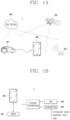
- the input unit 18 may include an input element such as at least one button, a switch, and a touch pad, and an output element such as a display module to receive a user command and output an operation state of the robot 100. For example, a command for the execution of the monitoring mode may be input through the display, and a state for the execution of the monitoring mode may be output.
- an input element such as at least one button, a switch, and a touch pad
- an output element such as a display module to receive a user command and output an operation state of the robot 100. For example, a command for the execution of the monitoring mode may be input through the display, and a state for the execution of the monitoring mode may be output.
- the plurality of transmitters 200 are installed in the boundary region 1200 of the driving region 1000 to transmit transmission signals.
- the plurality of transmitters 200 may be dispersedly installed in the boundary region 1200.
- the plurality of transmitters 200 may be dispersedly installed at each corner of the boundary region 1200.
- at least three of the plurality of transmitters 200 are dispersedly installed in the boundary region 1200 to transmit the transmission signals from the installed positions, respectively.
- each of the plurality of transmitters 200 dispersedly installed in the boundary region 1200 may transmit the transmission signal, which is a basis for determining the position of the robot 100 and setting the boundary region 1200.
- the transmission signal transmitted from each of the plurality of transmitters 200 may be received by the robot 100 and the terminal 300.
- map information of a region including the driving region 1000 is stored in the communication target element 600 stores and provided to the communication target device.
- the communication target element 600 may be the web server 600, and the communication target device may be the robot 100 or the terminal 300.
- the web server 600 may directly communicate with the robot 100 or perform communication with the robot 100 while communicating with the terminal 300 that communicates with the robot 100.
- the communication target element 600 may store control information related to the control of the system 1. For instance, data related to an application of the robot 100 or the terminal 300 or data related to an operation history of the robot 100 may be stored. Accordingly, remote control of the system 1 may be performed through the communication target element 600.
- the communication target element 600 may store the map information including the driving region 1000, and provide the map information to at least one of the robot 100 and the terminal 300.
- the map information may be a commercial map provided on the web, for instance, a Google map.
- the map information may be provided in the form of a CAD drawing, and the robot 100 may determine at least one of a position, a terrain, a feature, an area, an azimuth, and an actual measurement of the driving region 1000 using the map information.
- the communication target element 600 may receive information on the current position of the robot 100 from the GPS satellite 400.
- the robot 100 generates first map data for the positions of the plurality of transmitters 200 based on a reception result of the transmission signal, and receives second map data for a region corresponding to the driving region 1000 from the communication target element 600 to match the first map data and the second map data and generate boundary information of the driving region 1000.
- the robot 100 may receive the second map data through the communication unit 12 communicating with the communication target element 600.
- the boundary information may refer to virtual boundary information set as the boundary region 1200. Accordingly, the robot 100 may set the boundary region 1200 according to the boundary information to drive in the driving region 1000.
- the boundary information may be coordinate information of a portion corresponding to the boundary region 1200 on the coordinate information based on any one point on the driving region 1000.
- the first map data may be map information generated by the robot 100.
- the first map data which is map information generated based on a result of receiving the transmission signal, may be map information on the installation positions of the plurality of transmitters 200.
- the first map data may be map information in a form in which points UI to U6 corresponding to the positions where the plurality of transmitters 200 are installed are displayed, as illustrated in FIG. 7A . That is, the robot 100 may determine the positions of the plurality of transmitters 200 based on the reception result, and generate the first map data as illustrated in FIG. 7A .
- the second map data may be map information generated by the communication target element 600.
- the second map data which is map information for a region corresponding to the driving region 1000 from the map information stored in the communication target element 600, may be actual map information of the driving region 1000.
- the second map data may be map information according to actual terrains and features on the driving region 1000. That is, the communication target element 600 may determine an area corresponding to the driving region 1000 on the map information, and generate the second map data as illustrated in FIG. 7B .
- the robot 100 may match the first map data and the second map data as illustrated in FIGS. 7A and 7B , respectively to generate the boundary information, thereby setting the boundary region 1200.
- the plurality of transmitters 200 may be dispersedly installed in the boundary region 1200 and then transmit the transmission signals, respectively.
- the robot 100 may determine the position of each of the plurality of transmitters 200 based on a reception result of the transmission signals transmitted from each of the plurality of transmitters 200 to generate the first map data (P1).
- the communication target element 600 may generate the second map data according to a current position of the robot 100.
- the communication target element 600 may determine the current position of the robot 100 to generate the second map data.
- the communication target element 600 may transmit area information corresponding to the current position obtained from the map information to the robot 100, and receive designation information on a portion corresponding to the driving region 1000 on the area information from the robot 100 to generate the second map data according to the designation information (P2).
- the communication target element 600 may detect the area information to transmit the detected area information to the robot 100, and receive the designation information to generate the second map data according to the designation information (P2) when the designation information is designated by the robot 100.
- the communication target element 600 may detect the area information corresponding to the current position from the map information based on the current location and transmit the detected area information to the robot 100. Then, when the designation information corresponding to the driving region 1000 in the area information is designated by the robot 100, the designation information may be received from the robot 100. After receiving the designation information, the communication target element 600 may generate the second map data according to the designated information (P2), and then transmit the second map data to the robot 100.
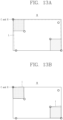
- the robot 100 may determine coordinate values corresponding to the position of any one transmitter from the first coordinate information (B3), and detect a reference point aligning with the coordinate values from the second coordinate information (B4) to align the first coordinate information and the second coordinate information based on the coordinate values and the reference point (B5 and B6) so as to match the first map data and the second map data. As illustrated in FIG. 10A , the robot 100 may determine the coordinate values R corresponding to the position of any one transmitter from the first coordinate information M1 (B3).
- the robot 100 may measure a plurality of adjustment references based on actual distances between the plurality of two points, respectively, and estimated distances corresponding to the plurality of two points, respectively, and calculate an average value of the plurality of adjustment references, thereby allowing the average value measured from each of the plurality of two points to be commonly reflected to each distance between the coordinates of the first coordinate information M1.
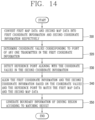
- the generation method includes converting the first map data and the second map data into first coordinate information M1 and second coordinate information M2, respectively (S10), determining coordinate values R corresponding to a position of any one transmitter from the first coordinate information M1 (S20), detecting a reference point C that aligns with the coordinate values R from the second coordinate information M2 (S30), aligning the first coordinate information M1 and the second coordinate information M2 based on the coordinate values R and the reference point C to match the first map data and the second map data (S40), and generating boundary information of the driving region 1000 according to the matching result (S50).
- the generation of the boundary information in the system 1 may include the converting step (S10), the determining step (S20), the detecting step (S30), the matching step (S40), and the generating step (S50).
- the robot 100 or the terminal 300 may generate the boundary information in the order of converting the first map data and the second map data into the first coordinate information M1 and the second coordinate information M2, respectively (S10), determining the coordinate values R from the first coordinate information M1 (S20), detecting the reference point C from the second coordinate information M2 (S30), and aligning the first coordinate information M1 and the second coordinate information M2 based on the coordinate values (R) and the reference point (C) to match the first map data and the second map data (S40) to generate the boundary information (S50).
- the converting step (S10) may be generating, by the robot 100 or the terminal 300, the first map data based on a result of receiving the transmission signals transmitted from the plurality of transmitters 200, respectively, receiving the second map data from the communication target element 600, and then converting the first map data and the second map data into the first coordinate information M1 and the second coordinate information M2, respectively.
- the robot 100 or the terminal 300 may determine coordinates corresponding to a position of any one of the transmitters located in the outermost periphery among coordinates on the first coordinate information M1 as the coordinate values. For instance, as illustrated in FIG. 10A , the coordinates R corresponding to the position of the transmitter located at an upper left end of the driving region 1000 may be determined as the coordinate values (B3).
- the robot 100 or the terminal 300 may detect a point that aligns with the coordinate value R in the second coordinate information M2, or that is closest to the coordinate values R as the reference point C. For instance, when the coordinate values R are determined as illustrated in FIG. 10A , a vertex C at an upper left end of the driving region 1000 may be detected as the reference point C as illustrated in FIG. 10B .
- the matching step (S40) may be aligning, by the robot 100 or the terminal 300, the first coordinate information M1 and the second coordinate information M2 based on the coordinate values R and the reference point C to match the first map data and the second map data.
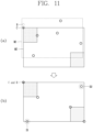
- the robot 100 or the terminal 300 may align the coordinate values R of the first coordinate information M1 with the reference point C of the second coordinate information M2, and overlap the first coordinate information M1 with the second coordinate information M2. Accordingly, as illustrated in (b) of FIG. 11 , the coordinates of the first coordinate information M1 may be disposed on the second coordinate information M2.
- the robot 100 or the terminal 300 may match the coordinate values R and the reference point C, and then, adjust at least one of an angle and a ratio of the first coordinate information M1 based on the coordinate values R to match the first coordinate information M1 to the second coordinate information M2. For instance, after aligning the coordinate values R with the reference point C as illustrated in (b) of FIG. 11 , at least one of an angle and a ratio of the first coordinate information M1 may be adjusted based on the coordinate values R such that the remaining coordinates of the first coordinate information M1 are exactly disposed on the second coordinate information M2 to align the first coordinate information with the second coordinate information.
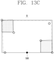
- the robot 100 or the terminal 300 may detect an actual distance between any two points on the driving region 1000, detect an estimated distance between coordinates corresponding to the two points, respectively, on the first coordinate information M1, and measure an adjustment reference based on the actual distance and the estimated distance, thereby reflecting the adjustment reference to the first coordinate information M1 to adjust a ratio of the first coordinate information M.
- the adjustment reference measured based on the actual distance and the estimated distance may be reflected to a distance between coordinates on the first coordinate information M1 to adjust a distance ratio between the coordinates while the coordinate values R are aligned with the reference point C, thereby allowing the errors D1 and D2 between the first coordinate information M1 and the second coordinate information M2 to be within the predetermined range.
- the robot 100 or the terminal 300 may detect an actual distance between the reference point C and any one straight line point on a straight line to the reference point C, detect an estimated distance between the coordinate values R and adjacent values adjacent to the straight line point on the first coordinate information M1, and measure the adjustment reference based on the reference point C and the straight line point, thereby reflecting the adjustment reference to each distance between the coordinates of the first coordinate information M1.
- the adjustment reference when measuring the adjustment reference to reflect it to each distance between the coordinates of the first coordinate information M1, the adjustment reference may be measured based on an actual distance between the reference point C and the straight line point, and an estimated distance between the coordinate values R and the adjacent values, corresponding to the actual distance on the coordinate information M1, thereby allowing the adjustment reference measured from the reference point C and the straight line point to be commonly reflected to each distance between the coordinates of the first coordinate information M1.
- the robot 100 or the terminal 300 may detect actual distances between a plurality of any two points, respectively, detect estimated distances between the coordinates corresponding to the plurality of any two points, respectively, and measure a plurality of adjustment references, respectively, based on a plurality of actual distances and a plurality of estimated distances, thereby reflecting the plurality of adjustment references to distances between the coordinates of the first coordinate information M1 corresponding thereto, respectively. That is, when measuring the adjustment reference to reflect it to each distance between the coordinates of the first coordinate information M1, as illustrated in FIG.
- a plurality of adjustment references may be measured based on actual distances between the plurality of two points, respectively, and estimated distances corresponding to the plurality of two points, respectively, thereby reflecting the plurality of adjustment references measured from the plurality of two points, respectively, to distances between the coordinates of the first coordinate information M1, respectively.
- the robot 100 or the terminal 300 may detect actual distances between a plurality of any two points, respectively, detect estimated distances between coordinates corresponding to the plurality of any two points, respectively, and measure a plurality of adjustment references based on a plurality of actual distances and a plurality of estimated distances, respectively, thereby reflecting an average value of the plurality of adjustment references to each distance between the coordinates of the first coordinate information M1. That is, when measuring the adjustment reference to reflect it to each distance between the coordinates of the first coordinate information M1, as illustrated in FIG.
- a plurality of adjustment references may be measured based on actual distances between the plurality of two points, respectively, and estimated distances corresponding to the plurality of two points, respectively, and calculate an average value of the plurality of adjustment references, thereby allowing the average value measured from each of the plurality of two points to be commonly reflected to each distance between the coordinates of the first coordinate information M1.
- the generating step (S50) may be generating, by the robot 100 or the terminal 300, the boundary information according to the matching result.
- the robot 100 or the terminal 300 may allow the matching result to be output and displayed on an outside of the robot 100 or the terminal 300, and generate the boundary information in response to a manipulation on the output display. That is, when matching the first map data and the second map data to generate the boundary information from the matching result, the matching result may be displayed externally, thereby generating the boundary information in response to a manipulation of at least one of correction, modification, and setting on the output display, and setting the boundary region 1200 according to the boundary information.
- the output display may be carried out through the input unit 18 of the robot 100 or carried out through the terminal 300.
Landscapes
- Engineering & Computer Science (AREA)
- Mechanical Engineering (AREA)
- Robotics (AREA)
- Radar, Positioning & Navigation (AREA)
- Automation & Control Theory (AREA)
- Aviation & Aerospace Engineering (AREA)
- Remote Sensing (AREA)
- Physics & Mathematics (AREA)
- General Physics & Mathematics (AREA)
- Life Sciences & Earth Sciences (AREA)
- Environmental Sciences (AREA)
- Orthopedic Medicine & Surgery (AREA)
- General Health & Medical Sciences (AREA)
- Health & Medical Sciences (AREA)
- Control Of Position, Course, Altitude, Or Attitude Of Moving Bodies (AREA)
Claims (13)
- Mobiles Robotersystem, das aufweist:mehrere Übertragungseinrichtungen (200), die in einem Grenzbereich eines Fahrbereichs (1000) installiert sind und konfiguriert sind, Übertragungssignale zu übertragen;ein Kommunikationszielelement (600), das konfiguriert ist, Karteninformationen eines Bereichs, der den Fahrbereich (1000) aufweist, zu speichern, um die Karteninformationen einer Kommunikationszielvorrichtung bereitzustellen; undeinen mobilen Roboter (100), der konfiguriert ist, erste Kartendaten für Positionen der mehreren Übertragungseinrichtungen (200) auf der Grundlage eines Empfangsergebnisses der Übertragungssignale zu erzeugen, und konfiguriert ist, zweite Kartendaten für einen Bereich, der dem Fahrbereich (1000) entspricht, von dem Kommunikationszielelement (600) zu empfangen, um die ersten Kartendaten und die zweiten Kartendaten so abzugleichen, dass Grenzinformationen des Fahrbereichs (1000) erzeugt werden,wobei die Karteninformationen eine auf einem Webspeicherort bereitgestellte kommerzielle Karte sind,wobei das Kommunikationszielelement (600) ein Webserver ist, auf dem Steuerinformationen bezüglich der Steuerung des mobilen Robotersystems gespeichert sind; undwobei das Kommunikationszielelement (600) konfiguriert ist, eine aktuelle Position des mobilen Roboters zu bestimmen und dann Gebietsinformationen, die dem aktuellen Standort entsprechen, aus den Karteninformationen an den mobilen Roboter (100) zu übertragen, und konfiguriert ist, Bezeichnungsinformationen für einen Teil, der dem Fahrbereich (1000) entspricht, auf den Gebietsinformationen zu empfangen, um die zweiten Kartendaten gemäß den Bezeichnungsinformationen zu erzeugen.
- Mobiles Robotersystem nach Anspruch 1, wobei mindestens drei der mehreren Übertragungseinrichtungen (200) in dem Grenzbereich verteilt installiert sind.
- Mobiles Robotersystem nach Anspruch 1, wobei der mobile Roboter (100) konfiguriert ist, die ersten Kartendaten und die zweiten Kartendaten in jeweils erste Koordinateninformationen und zweite Koordinateninformationen in demselben Koordinatensystem umzuwandeln und die ersten Kartendaten und die zweiten Kartendaten unter Verwendung der ersten Koordinateninformationen und der zweiten Koordinateninformationen abzugleichen.
- Mobiles Robotersystem nach Anspruch 3, wobei der mobile Roboter (100) konfiguriert ist, Koordinatenwerte zu bestimmen, die einer Position einer beliebigen Übertragungseinrichtung in den ersten Koordinateninformationen entsprechen, und konfiguriert ist, einen Referenzpunkt zu erfassen, der mit den Koordinatenwerten in den zweiten Koordinateninformationen übereinstimmt, um die ersten Koordinateninformationen und die zweiten Koordinateninformationen auf der Grundlage der Koordinatenwerte und des Referenzpunkts so auszurichten, dass die ersten Kartendaten und die zweiten Kartendaten übereinstimmen.
- Mobiles Robotersystem nach Anspruch 4, wobei der mobile Roboter (100) konfiguriert ist, die Koordinatenwerte am Referenzpunkt auszurichten und dann mindestens eines von einem Winkel und einem Verhältnis der ersten Koordinateninformationen auf der Grundlage der Koordinatenwerte anzupassen, um die ersten Koordinateninformationen mit den zweiten Koordinateninformationen auszurichten.
- Mobiles Robotersystem nach Anspruch 5, wobei der mobile Roboter (100) konfiguriert ist, die ersten Koordinateninformationen zu drehen, um einen Fehler zwischen den ersten Koordinateninformationen und den zweiten Koordinateninformationen innerhalb eines vorbestimmten Bereichs zu halten, während die Koordinatenwerte auf den Referenzpunkt fixiert sind, um so den Winkel der ersten Koordinateninformationen anzupassen.
- Mobiles Robotersystem nach Anspruch 5, wobei der mobile Roboter (100) konfiguriert ist, einen tatsächlichen Abstand zwischen zwei beliebigen Punkten im Fahrbereich (1000) zu erfassen, einen geschätzten Abstand zwischen Koordinaten, die den beiden Punkten entsprechen, jeweils auf den ersten Koordinateninformationen zu erfassen und eine Anpassungsreferenz auf der Grundlage des tatsächlichen Abstands und des geschätzten Abstands zu messen, um die Anpassungsreferenz für die ersten Koordinateninformationen widerzuspiegeln, um so ein Verhältnis der ersten Koordinateninformationen anzupassen.
- Mobiles Robotersystem nach Anspruch 7, wobei der mobile Roboter (100) konfiguriert ist, einen tatsächlichen Abstand zwischen dem Referenzpunkt und einem beliebigen Punkt auf einer geraden Linie auf einer geraden Linie zum Referenzpunkt zu erfassen, einen geschätzten Abstand zwischen den Koordinatenwerten und benachbarten Werten, die am Punkt auf der geraden Linie angrenzen, in den ersten Koordinateninformationen zu erfassen, und die Anpassungsreferenz auf der Grundlage des Referenzpunkts und des Punkts auf der geraden Linie zu messen, um so die Anpassungsreferenz für jeden Abstand zwischen den Koordinaten der ersten Koordinateninformationen widerzuspiegeln.
- Mobiles Robotersystem nach Anspruch 7, wobei der mobile Roboter (100) konfiguriert ist, jeweils tatsächliche Abstände zwischen mehreren von zwei beliebigen Punkten zu erfassen, um jeweils geschätzte Abstände zwischen Koordinaten zu erfassen, die den mehreren von zwei beliebigen Punkten entsprechen, und jeweils mehrere Anpassungsreferenzen auf der Grundlage mehrerer tatsächlicher Abstände und mehrerer geschätzter Abstände zu messen, um so jeweils die mehreren Anpassungsreferenzen für Abstände zwischen den Koordinaten der ersten Koordinateninformationen widerzuspiegeln.
- Mobiles Robotersystem nach Anspruch 7, wobei der mobile Roboter (100) konfiguriert ist, jeweils die tatsächlichen Abstände zwischen mehreren von zwei beliebigen Punkten zu erfassen, um jeweils die geschätzten Abstände zwischen den Koordinaten zu ermitteln, die den mehreren von zwei beliebigen Punkten entsprechen, und um jeweils mehrere Anpassungsreferenzen auf der Grundlage mehrerer tatsächlicher Abstände und mehrerer geschätzter Abstände zu messen, um so einen Durchschnittswert der mehreren Anpassungsreferenzen für jeden Abstand zwischen den Koordinaten der ersten Koordinateninformationen widerzuspiegeln.
- Mobiles Robotersystem nach Anspruch 1, wobei der mobile Roboter (100) konfiguriert ist zu ermöglichen, ein Abgleichergebnis ausgegeben und an einer Außenseite des mobilen Roboters oder auf einem Steuerelement, das den mobilen Roboter steuert, anzuzeigen, und konfiguriert ist, die Grenzinformationen als Reaktion auf eine Bearbeitung der Anzeige der Ausgabe zu erzeugen.
- Mobiles Robotersystem nach Anspruch 1, wobei der mobile Roboter (100) konfiguriert ist, Bilddaten für jeden Prozess zu speichern, in dem die Erzeugung der Grenzinformationen durch Abgleichen der ersten Kartendaten und der zweiten Kartendaten durchgeführt wird.
- Verfahren zum Erzeugen von Grenzinformationen in einem mobilen Robotersystem, das aufweist:mehrere Übertragungseinrichtungen (100), die in einem Grenzbereich eines Fahrbereichs (1000) installiert sind, um Übertragungssignale zu übertragen;ein Kommunikationszielelement (600), das Karteninformationen eines Bereichs einschließlich des Fahrbereichs speichert, um die Karteninformationen einer Kommunikationszielvorrichtung bereitzustellen; undeinen mobilen Roboter (100), der erste Kartendaten für Positionen der mehreren Übertragungseinrichtungen (200) auf der Grundlage eines Empfangsergebnisses der Übertragungssignale erzeugt, zweite Kartendaten für einen Bereich, der dem Fahrbereich entspricht, von dem Kommunikationszielelement empfängt, um auf der Grundlage der ersten Kartendaten und der zweiten Kartendaten Grenzinformationen des Fahrbereichs (1000) zu erzeugen, wobei das Verfahren aufweist:Umwandeln der ersten Kartendaten und der zweiten Kartendaten in jeweils erste Koordinateninformationen und zweite Koordinateninformationen;Bestimmen von Koordinatenwerten, die einer Position einer beliebigen Übertragungseinrichtung in den ersten Koordinateninformationen entsprechen;Erfassen eines Referenzpunkts, der mit den Koordinatenwerten in den zweiten Koordinateninformationen ausgerichtet ist;Ausrichten der ersten Kartendaten und der zweiten Kartendaten auf der Grundlage der Koordinatenwerte und des Referenzpunkts, um die ersten Koordinateninformationen und die zweiten Koordinateninformationen abzugleichen; undErzeugen von Grenzinformationen des Fahrbereichs (1000) gemäß dem Abgleichungsergebnis,wobei die Karteninformationen eine auf einem Webspeicherort bereitgestellte kommerzielle Karte sind,wobei das Kommunikationszielelement (600) ein Webserver ist, auf dem Steuerinformationen bezüglich der Steuerung des mobilen Robotersystems gespeichert sind; undwobei das Kommunikationszielelement eine aktuelle Position des mobilen Roboters bestimmt und dann Gebietsinformationen, die der aktuellen Position entsprechen, aus den Karteninformationen an den mobilen Roboter überträgt und Bezeichnungsinformationen für einen Teil, der dem Fahrbereich auf den Gebietsinformationen entspricht, empfängt, um die zweiten Kartendaten gemäß den Bezeichnungsinformationen zu erzeugen.
Applications Claiming Priority (2)
| Application Number | Priority Date | Filing Date | Title |
|---|---|---|---|
| KR1020190161892A KR102385611B1 (ko) | 2019-12-06 | 2019-12-06 | 이동 로봇 시스템 및 이동 로봇 시스템의 경계 정보 생성 방법 |
| PCT/KR2020/014469 WO2021112402A1 (ko) | 2019-12-06 | 2020-10-22 | 이동 로봇 시스템 및 이동 로봇 시스템의 경계 정보 생성 방법 |
Publications (3)
| Publication Number | Publication Date |
|---|---|
| EP4074469A1 EP4074469A1 (de) | 2022-10-19 |
| EP4074469A4 EP4074469A4 (de) | 2023-11-01 |
| EP4074469B1 true EP4074469B1 (de) | 2025-07-09 |
Family
ID=76222522
Family Applications (1)
| Application Number | Title | Priority Date | Filing Date |
|---|---|---|---|
| EP20896675.4A Active EP4074469B1 (de) | 2019-12-06 | 2020-10-22 | Mobiles robotersystem und verfahren zum erzeugen von grenzinformationen eines mobilen robotersystems |
Country Status (4)
| Country | Link |
|---|---|
| US (1) | US20220386522A1 (de) |
| EP (1) | EP4074469B1 (de) |
| KR (1) | KR102385611B1 (de) |
| WO (1) | WO2021112402A1 (de) |
Families Citing this family (1)
| Publication number | Priority date | Publication date | Assignee | Title |
|---|---|---|---|---|
| WO2025164880A1 (ko) * | 2024-01-29 | 2025-08-07 | 주식회사 도구공간 | 하이브리드 맵 기반 로봇의 제어 방법 |
Family Cites Families (11)
| Publication number | Priority date | Publication date | Assignee | Title |
|---|---|---|---|---|
| JPH07107644B2 (ja) * | 1986-02-28 | 1995-11-15 | 株式会社小松製作所 | ロボットの制御方法 |
| KR101457148B1 (ko) * | 2008-05-21 | 2014-10-31 | 삼성전자 주식회사 | 로봇의 위치 추정 장치 및 그 방법 |
| US20120290165A1 (en) * | 2011-05-09 | 2012-11-15 | Chien Ouyang | Flexible Robotic Mower |
| US9516806B2 (en) | 2014-10-10 | 2016-12-13 | Irobot Corporation | Robotic lawn mowing boundary determination |
| US9420741B2 (en) * | 2014-12-15 | 2016-08-23 | Irobot Corporation | Robot lawnmower mapping |
| US10405488B2 (en) * | 2014-12-23 | 2019-09-10 | Husqvarna Ab | Zone control system for a robotic vehicle |
| US10034421B2 (en) * | 2015-07-24 | 2018-07-31 | Irobot Corporation | Controlling robotic lawnmowers |
| KR102471487B1 (ko) * | 2015-10-26 | 2022-11-28 | 삼성전자주식회사 | 청소 로봇 및 그 제어방법 |
| KR101868374B1 (ko) * | 2016-10-20 | 2018-06-18 | 엘지전자 주식회사 | 이동 로봇의 제어방법 |
| KR102070068B1 (ko) * | 2017-11-30 | 2020-03-23 | 엘지전자 주식회사 | 이동 로봇 및 그 제어방법 |
| CN109085834B (zh) * | 2018-08-27 | 2019-09-03 | 珠海市一微半导体有限公司 | 机器人确定参考边的方法和机器人筛选参考墙边的方法 |
-
2019
- 2019-12-06 KR KR1020190161892A patent/KR102385611B1/ko active Active
-
2020
- 2020-10-22 US US17/782,650 patent/US20220386522A1/en active Pending
- 2020-10-22 WO PCT/KR2020/014469 patent/WO2021112402A1/ko not_active Ceased
- 2020-10-22 EP EP20896675.4A patent/EP4074469B1/de active Active
Also Published As
| Publication number | Publication date |
|---|---|
| KR20210071568A (ko) | 2021-06-16 |
| KR102385611B1 (ko) | 2022-04-12 |
| EP4074469A4 (de) | 2023-11-01 |
| US20220386522A1 (en) | 2022-12-08 |
| EP4074469A1 (de) | 2022-10-19 |
| WO2021112402A1 (ko) | 2021-06-10 |
Similar Documents
| Publication | Publication Date | Title |
|---|---|---|
| KR102292267B1 (ko) | 이동 로봇, 이동 로봇 시스템 및 이동 로봇의 충전대 이동 방법 | |
| AU2019208265B2 (en) | Moving robot, method for controlling the same, and terminal | |
| KR102060715B1 (ko) | 이동 로봇 및 그 제어방법 | |
| US11178811B2 (en) | Lawn mower robot, system of lawn mower robot and control method of lawn mower robot system | |
| EP3804491B1 (de) | Ladestation eines sich bewegenden roboters und sich bewegendes robotersystem | |
| EP3919237B1 (de) | Mobiler roboter und steuerungsverfahren dafür | |
| AU2020389328B2 (en) | Mobile robot system and boundary information generation method for mobile robot system | |
| US11914392B2 (en) | Moving robot system and method for generating boundary information of the same | |
| EP4074469B1 (de) | Mobiles robotersystem und verfahren zum erzeugen von grenzinformationen eines mobilen robotersystems |
Legal Events
| Date | Code | Title | Description |
|---|---|---|---|
| STAA | Information on the status of an ep patent application or granted ep patent |
Free format text: STATUS: THE INTERNATIONAL PUBLICATION HAS BEEN MADE |
|
| PUAI | Public reference made under article 153(3) epc to a published international application that has entered the european phase |
Free format text: ORIGINAL CODE: 0009012 |
|
| STAA | Information on the status of an ep patent application or granted ep patent |
Free format text: STATUS: REQUEST FOR EXAMINATION WAS MADE |
|
| 17P | Request for examination filed |
Effective date: 20220613 |
|
| AK | Designated contracting states |
Kind code of ref document: A1 Designated state(s): AL AT BE BG CH CY CZ DE DK EE ES FI FR GB GR HR HU IE IS IT LI LT LU LV MC MK MT NL NO PL PT RO RS SE SI SK SM TR |
|
| DAV | Request for validation of the european patent (deleted) | ||
| DAX | Request for extension of the european patent (deleted) | ||
| A4 | Supplementary search report drawn up and despatched |
Effective date: 20230929 |
|
| RIC1 | Information provided on ipc code assigned before grant |
Ipc: G05D 1/02 20200101ALI20230925BHEP Ipc: A01D 34/00 20060101ALI20230925BHEP Ipc: B25J 11/00 20060101ALI20230925BHEP Ipc: B25J 9/16 20060101AFI20230925BHEP |
|
| STAA | Information on the status of an ep patent application or granted ep patent |
Free format text: STATUS: EXAMINATION IS IN PROGRESS |
|
| 17Q | First examination report despatched |
Effective date: 20240717 |
|
| REG | Reference to a national code |
Ref country code: DE Ref legal event code: R079 Free format text: PREVIOUS MAIN CLASS: B25J0009160000 Ipc: G05D0001000000 Ref document number: 602020054386 Country of ref document: DE |
|
| GRAP | Despatch of communication of intention to grant a patent |
Free format text: ORIGINAL CODE: EPIDOSNIGR1 |
|
| STAA | Information on the status of an ep patent application or granted ep patent |
Free format text: STATUS: GRANT OF PATENT IS INTENDED |
|
| RIC1 | Information provided on ipc code assigned before grant |
Ipc: B25J 9/16 20060101ALI20250123BHEP Ipc: A01D 34/00 20060101ALI20250123BHEP Ipc: G05D 1/00 20060101AFI20250123BHEP |
|
| INTG | Intention to grant announced |
Effective date: 20250206 |
|
| GRAS | Grant fee paid |
Free format text: ORIGINAL CODE: EPIDOSNIGR3 |
|
| GRAA | (expected) grant |
Free format text: ORIGINAL CODE: 0009210 |
|
| STAA | Information on the status of an ep patent application or granted ep patent |
Free format text: STATUS: THE PATENT HAS BEEN GRANTED |
|
| AK | Designated contracting states |
Kind code of ref document: B1 Designated state(s): AL AT BE BG CH CY CZ DE DK EE ES FI FR GB GR HR HU IE IS IT LI LT LU LV MC MK MT NL NO PL PT RO RS SE SI SK SM TR |
|
| REG | Reference to a national code |
Ref country code: GB Ref legal event code: FG4D |
|
| REG | Reference to a national code |
Ref country code: CH Ref legal event code: EP |
|
| REG | Reference to a national code |
Ref country code: IE Ref legal event code: FG4D |
|
| REG | Reference to a national code |
Ref country code: DE Ref legal event code: R096 Ref document number: 602020054386 Country of ref document: DE |
|
| REG | Reference to a national code |
Ref country code: NL Ref legal event code: MP Effective date: 20250709 |