EP4074212B1 - Package - Google Patents
Package Download PDFInfo
- Publication number
- EP4074212B1 EP4074212B1 EP21211687.5A EP21211687A EP4074212B1 EP 4074212 B1 EP4074212 B1 EP 4074212B1 EP 21211687 A EP21211687 A EP 21211687A EP 4074212 B1 EP4074212 B1 EP 4074212B1
- Authority
- EP
- European Patent Office
- Prior art keywords
- sleeve
- driving sleeve
- outer housing
- guiding
- package
- Prior art date
- Legal status (The legal status is an assumption and is not a legal conclusion. Google has not performed a legal analysis and makes no representation as to the accuracy of the status listed.)
- Active
Links
Images


Classifications
-
- A—HUMAN NECESSITIES
- A45—HAND OR TRAVELLING ARTICLES
- A45D—HAIRDRESSING OR SHAVING EQUIPMENT; EQUIPMENT FOR COSMETICS OR COSMETIC TREATMENTS, e.g. FOR MANICURING OR PEDICURING
- A45D40/00—Casings or accessories specially adapted for storing or handling solid or pasty toiletry or cosmetic substances, e.g. shaving soaps or lipsticks
- A45D40/06—Casings wherein movement of the lipstick or like solid is a screwing movement
-
- A—HUMAN NECESSITIES
- A45—HAND OR TRAVELLING ARTICLES
- A45D—HAIRDRESSING OR SHAVING EQUIPMENT; EQUIPMENT FOR COSMETICS OR COSMETIC TREATMENTS, e.g. FOR MANICURING OR PEDICURING
- A45D40/00—Casings or accessories specially adapted for storing or handling solid or pasty toiletry or cosmetic substances, e.g. shaving soaps or lipsticks
-
- A—HUMAN NECESSITIES
- A45—HAND OR TRAVELLING ARTICLES
- A45D—HAIRDRESSING OR SHAVING EQUIPMENT; EQUIPMENT FOR COSMETICS OR COSMETIC TREATMENTS, e.g. FOR MANICURING OR PEDICURING
- A45D40/00—Casings or accessories specially adapted for storing or handling solid or pasty toiletry or cosmetic substances, e.g. shaving soaps or lipsticks
- A45D40/12—Casings with provision for preventing undesired movement of the stick
-
- A—HUMAN NECESSITIES
- A45—HAND OR TRAVELLING ARTICLES
- A45D—HAIRDRESSING OR SHAVING EQUIPMENT; EQUIPMENT FOR COSMETICS OR COSMETIC TREATMENTS, e.g. FOR MANICURING OR PEDICURING
- A45D40/00—Casings or accessories specially adapted for storing or handling solid or pasty toiletry or cosmetic substances, e.g. shaving soaps or lipsticks
- A45D2040/0025—Details of lipstick or like casings
Definitions
- the present application relates to a container for cosmetic, more specifically, to a package.
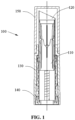
- a lipstick package 100 in general includes a cup 110, a guiding sleeve 120, a driving sleeve 130, an outer housing 140 and a cap 150.
- the cup 110 is configured to accommodate and hold a lipstick bar, and is arranged within the guiding sleeve 120.
- the cup 110 is provided with a transmission slider that protrudes out of the guiding sleeve 120 and passes through a through groove of a side wall of the guiding sleeve 120.
- the driving sleeve 130 is provided with a transmission spiral groove matching with the transmission slider, and is fixed to the outer housing 140.
- the user rotates the outer housing 140 to drive the driving sleeve 130 into rotation.
- the rotation of the driving sleeve 130 drives the cup 110 to move axially in the guiding sleeve 120 through the transmission spiral groove and the transmission slider.
- the lipstick bar can be exposed out of the guiding sleeve 120 for use.
- the cap 150 is capped on the outer housing 140.
- the guiding sleeve 120 is generally made of a metal, and other elements are generally made of plastics.
- Such packages for a lipstick are for instance known from US 2021/093070 A1 and US 2630215 A .
- embodiments of the present application provide a package, in which elements made of different materials can be separated from each other.
- the package is defined by the features of claim 1.
- the embodiments of the present application provide a package, which includes a cup, a guiding sleeve, a driving sleeve, and an outer housing.
- the cup is configured to accommodate and support a content.
- the guiding sleeve is disposed around the cup, and the cup is movable in the guiding sleeve in an axial direction of the guiding sleeve.
- the driving sleeve is configured to drive the cup to move in the axial direction, and the driving sleeve is disposed around the guiding sleeve.
- the outer housing is disposed around the driving sleeve and coupled to the driving sleeve.
- the guiding sleeve is detachably coupled to the driving sleeve and is rotatable relative to the driving sleeve in a circumferential direction.
- the outer housing includes a top end and a bottom end opposite to one another in the axial direction, and each of the top end and the bottom end is provided with an opening.
- the outer housing is detachably coupled to the driving sleeve, so that an assembly constituted by the driving sleeve, the guiding sleeve and the cup is capable to be separated from the outer housing from the bottom end of the outer housing.
- the top end of the outer housing is provided with a neck to limit an axial movement of the driving sleeve towards the top end of the outer housing, and an inner wall of the neck of the outer housing is in contact with an outer peripheral wall of the guiding sleeve.
- the guiding sleeve is provided with a first stopper
- the driving sleeve is provided with a second stopper matching with the first stopper, to limit a movement of the guiding sleeve relative to the driving sleeve in the axial direction.
- the first stopper includes a first stopping protrusion formed on an outer wall of the guiding sleeve in a circumferential direction.
- the second stopper includes a second stopping protrusion formed on an inner wall of the driving sleeve in a circumferential direction, the first stopping protrusion and the second stopping protrusion are configured to cooperate with one another to limit an axial movement of the guiding sleeve relative to the driving sleeve towards the top end of the outer housing.
- the second stopper includes a third stopping protrusion formed on the inner wall of the driving sleeve in the circumferential direction, the first stopping protrusion and the third stopping protrusion are configured to cooperate with one another to limit an axial movement of the guiding sleeve relative to the driving sleeve towards the bottom end of the outer housing.
- one of an outer wall of the driving sleeve and an inner wall of the outer housing is provided with at least one rib
- the other one of the outer wall of the driving sleeve and the inner wall of the outer housing is provided with at least one groove matching with the corresponding rib.
- the rib and the groove cooperate with one another to limit an axial movement or a circumferential movement of the driving sleeve relative to the outer housing.
- the groove is provided with a guiding surface for guiding the rib.
- an axial force required to detach the outer housing from the driving sleeve is less than an axial force required to detach the guiding sleeve from the driving sleeve.
- the package further includes a bottom plug detachably coupled to a bottom end of the driving sleeve, and the outer housing is arranged around an outer circumference wall of the bottom plug.
- the bottom plug is coupled to the bottom end of the driving sleeve through a snap-fit.
- an inner wall of the bottom end of the outer housing forms a dovetail-shaped hole, and the bottom plug is wedged into the dovetail-shaped hole.
- the package further includes an elastic ring mounted around the driving sleeve, the driving sleeve is provided with an annular groove for receiving the elastic ring, a depth of the annular groove is greater than a diameter of the elastic ring, the annular groove includes at least one empty area through which the elastic ring contacts an outer peripheral wall of the guiding sleeve.
- the driving sleeve is detachably coupled to the driving sleeve, so that the guiding sleeve can be separated from the driving sleeve.
- Embodiments of the present application 200 package; 210 cup; 211 holding ridge; 220 guiding sleeve; 221 first stopping protrusion; 222 strip-type groove; 230 driving sleeve; 231 rib; 232 engagement projection; 233 second stopping protrusion; 240 outer housing; 241 groove; 2411 guiding surface; 250 bottom plug; 251 slot.
- a package which includes a cup, a guiding sleeve, a driving sleeve, and an outer housing.
- the cup is configured to accommodate and support a content.
- the guiding sleeve is disposed around the cup, and the cup is movable in the guiding sleeve in an axial direction of the guiding sleeve.
- the driving sleeve is configured to drive the cup to move in the axial direction, and the driving sleeve is disposed around the guiding sleeve.
- the outer housing is disposed around the driving sleeve and coupled to the driving sleeve.
- the guiding sleeve is detachably coupled to the driving sleeve and is rotatable relative to the driving sleeve in a circumferential direction.
- the driving sleeve is detachably coupled to the guiding sleeve, so that the guiding sleeve can be separated from the driving sleeve in the axial direction.
- the package here may include a container for cosmetic, such as a package, but is not limited to the package.
- a container for cosmetic such as a package, but is not limited to the package.
- the package is taken as an example to illustrate the following specific embodiments.
- the embodiment provides a package 200.
- the package 200 includes a cup 210, a guiding sleeve 220, a driving sleeve 230, and an outer housing 240.
- the cup 210 is configured to accommodate and support a lipstick bar.
- the guiding sleeve 220 is disposed around the cup 210, and the cup 210 is movable in the guiding sleeve 220 in an axial direction of the guiding sleeve 220.
- the driving sleeve 230 is configured to drive the cup 210 to move in the axial direction, and the driving sleeve 230 is disposed around the guiding sleeve 220.
- the outer housing 240 is disposed around the driving sleeve 230 and is coupled to the driving sleeve 230.
- the guiding sleeve 220 is detachably coupled to the driving sleeve 230 and is rotatable relative to the driving sleeve 230 in a circumferential direction.
- the package in the embodiment is the package 200
- the content is the lipstick bar.
- an axial direction of the guiding sleeve may be an axial direction of the package 200, that is, the axial direction of the guiding sleeve is also an axial direction of the cup 210, an axial direction of the driving sleeve 230, and an axial direction of the outer housing 240. Therefore, the axial direction mentioned below is the axial direction of the guiding sleeve, unless otherwise explained.
- the guiding sleeve 220 is made of a metal, and other elements are all made of plastics. According to an optional embodiment of the present application, the guiding sleeve 220 may be provided with a first stopper, and the driving sleeve 230 is provided with a second stopper matching with the first stopper, to limit a movement of the guiding sleeve 220 relative to the driving sleeve 230 in the axial direction.
- the first stopper includes a first stopping protrusion 221 formed on an outer wall of the guiding sleeve 220 in a circumferential direction.
- the second stopper includes second stopping protrusions 233 formed on an inner wall of the driving sleeve 230 in a circumferential direction.
- the first stopping protrusion 221 and the second stopping protrusions 233 are configured to cooperate with one another to limit an axial movement of the guiding sleeve 220 relative to the driving sleeve 230 towards the top end of the outer housing 240.
- the first stopping protrusion 221 is an annular protrusion.
- the second stopping protrusions 233 are also annular protrusions but are discontinuous in a circumferential direction, which facilitate injection molding of the driving sleeve 230.
- the second stopper further includes third stopping protrusions 234 formed on the inner wall of the driving sleeve 230 in the circumferential direction.
- the first stopping protrusion 221 and the third stopping protrusions 234 are configured to cooperate with one another to limit an axial movement of the guiding sleeve 220 relative to the driving sleeve 230 towards the bottom end of the outer housing 240.
- the first stopping protrusion 221, the second stopping protrusions 233, and the third stopping protrusions 234 can limit an axial position of the guiding sleeve 220 relative to the driving sleeve 230 without hindering relative rotation of the guiding sleeve 220 and the driving sleeve 230 in the circumferential direction.
- a shape of the first stopping protrusion 221 is continuous in the circumferential direction, which is more convenient for manufacturing.
- Both the second stopping protrusions 233 and the third stopping protrusions 234 are formed at intervals on the inner wall of the driving sleeve 230 in the circumferential direction, which is more convenient for de-molding the driving sleeve 230 after the injection molding.
- the guiding sleeve 220 may be directly pulled out upward.
- a direction of a force is as shown by F0.
- F0 a direction of a force
- at least one of the first stopping protrusion 221 and the second stopping protrusion 233 is slightly deformed, so that the second stopping protrusion 233 cannot limit the first stopping protrusion 221, and the first stopping protrusion 221 moves upward, that is, the guiding sleeve 220 moves upward and is separated from the driving sleeve 230.
- the purpose of separating the guiding sleeve 220 made of a medal from the driving sleeve 230 made of plastics in the axial direction may be achieved, and the guiding sleeve 220 and the driving sleeve 230 will not be damaged.
- the foregoing slight deformation may be an elastic deformation or a combination of both the elastic deformation and a minute plastic deformation.
- the driving sleeve 230 may be made of plastics with good elasticity.
- a fixing structure for fixing the guiding sleeve 220 and the driving sleeve 230 with each other may be other structures except the first stopping protrusion 221, the second stopping protrusion 233 and the third stopping protrusion 234, that is, other structures that can limit an axial position of the guiding sleeve 220 relative to the driving sleeve 230 without hindering relative rotation of the guiding sleeve 220 and the driving sleeve 230 in the circumferential direction.
- the section of each of the first stopping protrusion 221 and the second stopping protrusion 233 in the longitudinal direction may have a circular arc shape, so that it is more convenient to separate the guiding sleeve 220 from the driving sleeve 230.
- the embodiment provides a package 200, which, based on the first embodiment, further includes an outer housing as described below.
- the outer housing 240 includes a top end and a bottom end opposite to one another in an axial direction, and each of the top end and the bottom end is provided with an opening.
- the outer housing 240 is detachably coupled to the driving sleeve 230, so that an assembly constituted by the driving sleeve 230, the guiding sleeve 220 and the cup 210 is capable to be separated from the outer housing 240 from the bottom end of the outer housing 240.
- the top end of the outer housing 240 is provided with a neck to limit an axial movement of the driving sleeve 230 towards the top end of the outer housing 240, and an inner wall of the neck of the outer housing 240 is in contact with an outer peripheral wall of the guiding sleeve 220.
- the outer housing 240 and the guiding sleeve 220 are tightly assembled together, which easily prevents entry of dust. It is also not easy to see lower elements from above, which makes it more aesthetically pleasing, and facilitates the cooperation of the outer housing and a cap of the package.
- one of an outer wall of the driving sleeve 230 and an inner wall of the outer housing 240 is provided with at least one rib, and the other one of the outer wall of the driving sleeve 230 and the inner wall of the outer housing 240 is provided with at least one groove matching with corresponding rib.
- the rib and the groove cooperate with one another to limit an axial movement or a circumferential movement of the driving sleeve relative to the outer housing.
- the driving sleeve 230 may be provided with at least one rib 231 disposed on the outer wall of the driving sleeve 230.
- the outer housing 240 may be provided with a groove 241 matching with the rib 231, and the groove 241 is disposed at the inner wall of the outer housing 240.
- the cooperation of the rib 231 and the groove 241 not only can limit the axial position of the driving sleeve 230 relative to the outer housing 240, but also can limit a circumferential position of the driving sleeve 230 relative to the outer housing 240, which is simple in structure and is easy in installation.
- the cooperation of the rib 231 and the groove 241 not only further limits a detachable structure between the driving sleeve 230 and the outer housing 240, but also limits an order for detaching the guiding sleeve 220. That is, the guiding sleeve 220 moves downward to drive the driving sleeve 230 to move downward, the rib 231 of the driving sleeve 230 is disengaged from the groove 241 of the outer housing 240, then the outer housing can be removed from above.
- the detaching process will be described in detail with respect to FIG. 7 below.
- the number of the ribs 231 may be 4, and the ribs 231 are evenly disposed in the circumferential direction, which is more reliable due to such a fixing structure.
- the groove 241 is provided with a guiding surface 2411 for guiding the rib 231.
- the specific detaching method may refer to FIG. 6 , that is, a pushing force F1 is applied to the top end of the guiding sleeve 220 to drive the driving sleeve 230 to move downward.
- a pushing force F1 is applied to the top end of the guiding sleeve 220 to drive the driving sleeve 230 to move downward.
- the driving sleeve 230 is disengaged from the lower end of the outer housing 240, and then the outer housing 240 is removed from above the driving sleeve 230.
- the elements of the package after removal may refer to FIG. 7 .
- the principle that the guiding sleeve 220 drives the driving sleeve 230 to move downward is as follows.
- the first stopping protrusion 221 on the guiding sleeve 220 squeezes the third stopping protrusion 234 on the driving sleeve 230, so as to push the driving sleeve 230 to move downward.
- the bottom end of the guiding sleeve 220 is in contact with a bottom plug 250 (see below) to drive the bottom plug 250 to move downward.
- the bottom plug 250 is coupled to the driving sleeve 230 through a snap-fit, to push the driving sleeve 230 to move downward.
- the user may hold the driving sleeve 230 with the rougher surface to detach the guiding sleeve 220.
- the specific detaching method may refer to FIG. 8 .
- One hand holds a lower end of the driving sleeve 230, and the other hand holds an upper end of the guiding sleeve 220 and applies a force F2 to the guiding sleeve 220, that is, the guiding sleeve 220 may be removed from the driving sleeve 230.
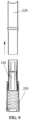
- the elements of the package after removal may refer to FIG. 9 .
- the package 200 may be designed in such a way that an axial force required to detach the outer housing 240 from the driving sleeve 230 is less than an axial force required to detach the guiding sleeve 220 from the driving sleeve 230.
- the axial force required to detach the guiding sleeve 220 from the driving sleeve 230 may be designed to be larger so as to prevent the user from a false action in use, since the lipstick bar cannot be used any more if the guiding sleeve 220 is disassembled.
- the force required for the detaching is the axial force.
- the outer housing 240 may be detached firstly, then the user holds the driving sleeve 230 with the rougher surface to detach the guiding sleeve 220 to more conveniently apply the pulling force to the guiding sleeve 220, so that the problem of laborious detaching or complex detaching caused by the larger axial force may be overcome.
- the axial force required to detach the guiding sleeve 220 from the driving sleeve 230 being designed to be larger may be realized by increasing an amount of interference fit, or may also be realized by changing a radius of the circular arc of the first stopping protrusion 221 or the second stopping protrusion 233.
- the package 200 may further include the bottom plug 250 detachably coupled to the bottom end of the driving sleeve 230, and the outer housing 240 is arranged around an outer circumference wall of the bottom plug 250. Since the cup 210, the guiding sleeve 220, and the driving sleeve 230 are hollow, the bottom plug 250 is required to close off the bottom of the package 200. In this way, the lipstick bar can remain sealed and moist, and also has a better appearance.
- the bottom plug 250 may be coupled to the bottom end of the driving sleeve 230 through a snap-fit, which is convenient to install.
- the driving sleeve 230 is provided with an engagement projection 232
- the bottom plug 250 has a slot 251 matching with the engagement projection 232.
- the package may be designed in such a way that an inner wall of the bottom end of the outer housing 240 forms a dovetail-shaped hole, and the bottom plug 250 is wedged into the dovetail-shaped hole. In this way, when the outer housing 240 is detached, the bottom plug does not hinder the outer housing 240 from removing upward, and it is not affected even a fit clearance becomes smaller due to a process error or thermal expansion.
- the bottom plug 250 and the driving sleeve 230 may be designed to be integrally formed, that is, the driving sleeve 230 is designed to be non-hollow. In this way, assembly operations may be reduced.
- the package further includes an elastic ring 260 mounted around the driving sleeve 230.
- the driving sleeve 230 is provided with an annular groove 235 for receiving the elastic ring 260, and a depth of the annular groove 235 is greater than a diameter of the elastic ring 260.
- the annular groove 235 includes at least one empty area through which the elastic ring 260 contacts an outer peripheral wall of the guiding sleeve 220.
- the elastic ring 260 can limit the rotation of the guiding sleeve 220 relative to the driving sleeve 230 by friction, that is, when the guiding sleeve 220 rotates relative to the driving sleeve 230, a damping force will be generated and felt by the user, which provides a better user experience.
- the magnitude of the damping force of the rotation of the guiding sleeve 220 relative to the driving sleeve 230 depends on a contact area between the elastic ring 260 and the guiding sleeve 220, that is, the magnitude of the damping force is related to the number and area of the empty areas of the annular groove 235.
- the annular groove 235 provides the following effect. Since the elastic ring 260 is located within the annular groove 235, the annular groove 235 can limit the position of the elastic ring 260 by friction, so that when the package is assembled or in use, the position of the elastic ring 260 will not be changed, thereby ensuring damping stability.
- annular groove 235 may prevent the elastic ring 260 from contacting other elements and using lubricating oil.
- the guiding sleeve 220 may include at least one strip-type groove 222 located at a sidewall of the guiding sleeve 220, and the cup 210 includes at least one transmission bump (not shown in drawings) that protrudes out of the outer wall of the guiding sleeve 220 and passes through the strip-type groove 222, so that the cup 210 is movable along the inner wall of the guiding sleeve 220 in the axial direction.
- the axial movement of the cup 210 along the inner wall of the guiding sleeve 220 in the axial direction is guided by the strip-type groove 222, the trajectory of the cup 210 is stable.
- the number of strip-type grooves 222 may be 2, and they are evenly disposed in the circumferential direction. Therefore, the cup 210 moves in a more even and reliable way.
- an inner wall of the cup 210 may further be provided with at least two holding ridges 211 that make the lipstick bar extend longitudinally. In this way, the shape of the lipstick bar is easily kept, and when the lipstick bar is loaded into the cup 210, the lipstick bar can also be guided to a certain extent.
- the number of holding ridges 211 may be 4, and are evenly disposed in the circumferential direction. In this way, the shape of the lipstick bar is easily kept.
- connection should be made in a broad understanding unless otherwise specified and defined.
- it may be an electrical connection, or it may be in communication inside two elements, and may be directly connected, or indirectly connected by an intermediate medium.
- connection may be made in a broad understanding unless otherwise specified and defined.
- it may be an electrical connection, or it may be in communication inside two elements, and may be directly connected, or indirectly connected by an intermediate medium.
- the specific meaning of the above terms may be understood by those of ordinary skill in the art according to specific situations.
- first/second/third are only used to distinguish similar objects, which do not represent specific sequence for the objects. It may be understood that the terms “first/second/third” can interchange, if permitted, the sequential or chronological order.
Landscapes
- Containers And Packaging Bodies Having A Special Means To Remove Contents (AREA)
- Passenger Equipment (AREA)
Description
- The present application relates to a container for cosmetic, more specifically, to a package.
- Lipstick is a commonly used cosmetic, and generally is received in a lipstick package. As shown in
Fig. 1 , alipstick package 100 in general includes acup 110, a guidingsleeve 120, adriving sleeve 130, anouter housing 140 and acap 150. Thecup 110 is configured to accommodate and hold a lipstick bar, and is arranged within the guidingsleeve 120. Thecup 110 is provided with a transmission slider that protrudes out of the guidingsleeve 120 and passes through a through groove of a side wall of the guidingsleeve 120. Thedriving sleeve 130 is provided with a transmission spiral groove matching with the transmission slider, and is fixed to theouter housing 140. In use, the user rotates theouter housing 140 to drive thedriving sleeve 130 into rotation. The rotation of thedriving sleeve 130 drives thecup 110 to move axially in the guidingsleeve 120 through the transmission spiral groove and the transmission slider. In this way, the lipstick bar can be exposed out of the guidingsleeve 120 for use. After the use, thecap 150 is capped on theouter housing 140. In the package, the guidingsleeve 120 is generally made of a metal, and other elements are generally made of plastics. Such packages for a lipstick are for instance known fromUS 2021/093070 A1 andUS 2630215 A . - With the stricter demand of environmental protection, more and more attention is paid to material recycling. During the material recycling, elements made of different materials should be separated from each other, and elements made of the same material should be collected together. However, for the existing lipstick package, it is difficult to separate the metallic guiding
sleeve 120 from the other elements made of plastics, such as thecup 110, thedriving sleeve 130 or theouter housing 140. - In view of this, embodiments of the present application provide a package, in which elements made of different materials can be separated from each other.
- In order to achieve the forgoing objective, the package is defined by the features of claim 1.
- The embodiments of the present application provide a package, which includes a cup, a guiding sleeve, a driving sleeve, and an outer housing.
- The cup is configured to accommodate and support a content.
- The guiding sleeve is disposed around the cup, and the cup is movable in the guiding sleeve in an axial direction of the guiding sleeve.
- The driving sleeve is configured to drive the cup to move in the axial direction, and the driving sleeve is disposed around the guiding sleeve.
- The outer housing is disposed around the driving sleeve and coupled to the driving sleeve.
- In the package, the guiding sleeve is detachably coupled to the driving sleeve and is rotatable relative to the driving sleeve in a circumferential direction.
- The outer housing includes a top end and a bottom end opposite to one another in the axial direction, and each of the top end and the bottom end is provided with an opening. The outer housing is detachably coupled to the driving sleeve, so that an assembly constituted by the driving sleeve, the guiding sleeve and the cup is capable to be separated from the outer housing from the bottom end of the outer housing.
- Preferably, the top end of the outer housing is provided with a neck to limit an axial movement of the driving sleeve towards the top end of the outer housing, and an inner wall of the neck of the outer housing is in contact with an outer peripheral wall of the guiding sleeve.
- Preferably, the guiding sleeve is provided with a first stopper, and the driving sleeve is provided with a second stopper matching with the first stopper, to limit a movement of the guiding sleeve relative to the driving sleeve in the axial direction.
- Preferably, the first stopper includes a first stopping protrusion formed on an outer wall of the guiding sleeve in a circumferential direction.
- The second stopper includes a second stopping protrusion formed on an inner wall of the driving sleeve in a circumferential direction, the first stopping protrusion and the second stopping protrusion are configured to cooperate with one another to limit an axial movement of the guiding sleeve relative to the driving sleeve towards the top end of the outer housing.
- Preferably, the second stopper includes a third stopping protrusion formed on the inner wall of the driving sleeve in the circumferential direction, the first stopping protrusion and the third stopping protrusion are configured to cooperate with one another to limit an axial movement of the guiding sleeve relative to the driving sleeve towards the bottom end of the outer housing.
- Preferably, one of an outer wall of the driving sleeve and an inner wall of the outer housing is provided with at least one rib, and the other one of the outer wall of the driving sleeve and the inner wall of the outer housing is provided with at least one groove matching with the corresponding rib. The rib and the groove cooperate with one another to limit an axial movement or a circumferential movement of the driving sleeve relative to the outer housing.
- Preferably, the groove is provided with a guiding surface for guiding the rib.
- Preferably, an axial force required to detach the outer housing from the driving sleeve is less than an axial force required to detach the guiding sleeve from the driving sleeve.
- Preferably, the package further includes a bottom plug detachably coupled to a bottom end of the driving sleeve, and the outer housing is arranged around an outer circumference wall of the bottom plug.
- Preferably, the bottom plug is coupled to the bottom end of the driving sleeve through a snap-fit.
- Preferably, an inner wall of the bottom end of the outer housing forms a dovetail-shaped hole, and the bottom plug is wedged into the dovetail-shaped hole.
- Preferably, the package further includes an elastic ring mounted around the driving sleeve, the driving sleeve is provided with an annular groove for receiving the elastic ring, a depth of the annular groove is greater than a diameter of the elastic ring, the annular groove includes at least one empty area through which the elastic ring contacts an outer peripheral wall of the guiding sleeve.
- According to the package of the embodiments of the present application, the driving sleeve is detachably coupled to the driving sleeve, so that the guiding sleeve can be separated from the driving sleeve.
- Other beneficial effects of the embodiments of the present application will be further described in conjunction with specific technical solutions.
- In order to more clearly describe the technical solutions in the embodiments of the present application, the following will briefly describe the drawings used in the description of the embodiments. It should be understood that the drawings described below are only a part of the drawings of the embodiments of the present application. For those of ordinary skill in the art, other drawings can be obtained from these drawings without creative work.
-
FIG. 1 is a schematic view of a package in the related art. -
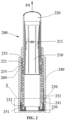
FIG. 2 is a schematic view of a package of an embodiment of the present application. -
FIG. 3 is a schematic view of a guiding sleeve of a package of an embodiment of the present application. -
FIG. 4 is a schematic view of a driving sleeve of a package of an embodiment of the present application. -
FIG. 5 is a partial enlarged view of a part A inFIG. 2 . -
FIG. 6 is a schematic diagram shows a force applied for detaching an outer housing of a package of an embodiment of the present application. -
FIG. 7 is a schematic diagram shows a package of an embodiment of the present application after an outer housing is detached. -
FIG. 8 is a schematic diagram shows a force applied for detaching a guiding sleeve of a package of an embodiment of the present application. -
FIG. 9 is a schematic diagram shows a package of an embodiment of the present application after a guiding sleeve is detached. - Related art: 100 package; 110 cup; 120 guiding sleeve; 130 driving sleeve; 140 outer housing; 150 cap.
- Embodiments of the present application: 200 package; 210 cup; 211 holding ridge; 220 guiding sleeve; 221 first stopping protrusion; 222 strip-type groove; 230 driving sleeve; 231 rib; 232 engagement projection; 233 second stopping protrusion; 240 outer housing; 241 groove; 2411 guiding surface; 250 bottom plug; 251 slot.
- For the problem in related art, embodiments of the present application provide a package, which includes a cup, a guiding sleeve, a driving sleeve, and an outer housing.
- The cup is configured to accommodate and support a content.
- The guiding sleeve is disposed around the cup, and the cup is movable in the guiding sleeve in an axial direction of the guiding sleeve.
- The driving sleeve is configured to drive the cup to move in the axial direction, and the driving sleeve is disposed around the guiding sleeve.
- The outer housing is disposed around the driving sleeve and coupled to the driving sleeve.
- In the package, the guiding sleeve is detachably coupled to the driving sleeve and is rotatable relative to the driving sleeve in a circumferential direction.
- According to the package of the embodiments of the present application, the driving sleeve is detachably coupled to the guiding sleeve, so that the guiding sleeve can be separated from the driving sleeve in the axial direction.
- The package here may include a container for cosmetic, such as a package, but is not limited to the package. The package is taken as an example to illustrate the following specific embodiments.
- The following detailed description for the application will be further described below in conjunction with the drawings and specific embodiments. It should be understood that the specific embodiments described here is only used for explaining the present application, instead of limiting the present application. Moreover, the described embodiments below are a part of, but not all of the embodiments of the present application. According to these embodiments, all other embodiments obtained by those of ordinary skill in the art without creative work shall fall within the protection scope of this present application.
- The embodiment provides a
package 200. As shown inFIG. 2 , thepackage 200 includes acup 210, a guidingsleeve 220, a drivingsleeve 230, and anouter housing 240. - The
cup 210 is configured to accommodate and support a lipstick bar. - The guiding
sleeve 220 is disposed around thecup 210, and thecup 210 is movable in the guidingsleeve 220 in an axial direction of the guidingsleeve 220. - The driving
sleeve 230 is configured to drive thecup 210 to move in the axial direction, and the drivingsleeve 230 is disposed around the guidingsleeve 220. - The
outer housing 240 is disposed around the drivingsleeve 230 and is coupled to the drivingsleeve 230. - In the package, the guiding
sleeve 220 is detachably coupled to the drivingsleeve 230 and is rotatable relative to the drivingsleeve 230 in a circumferential direction. - That is, the package in the embodiment is the
package 200, and the content is the lipstick bar. - The
cup 210, the guidingsleeve 220, the drivingsleeve 230, and theouter housing 240 in the package of the embodiment are all disposed in the axial direction, therefore an axial direction of the guiding sleeve may be an axial direction of thepackage 200, that is, the axial direction of the guiding sleeve is also an axial direction of thecup 210, an axial direction of the drivingsleeve 230, and an axial direction of theouter housing 240. Therefore, the axial direction mentioned below is the axial direction of the guiding sleeve, unless otherwise explained. - In the embodiment, the guiding
sleeve 220 is made of a metal, and other elements are all made of plastics. According to an optional embodiment of the present application, the guidingsleeve 220 may be provided with a first stopper, and the drivingsleeve 230 is provided with a second stopper matching with the first stopper, to limit a movement of the guidingsleeve 220 relative to the drivingsleeve 230 in the axial direction. - According to an optional embodiment of the present application, the first stopper includes a first stopping
protrusion 221 formed on an outer wall of the guidingsleeve 220 in a circumferential direction. - The second stopper includes second stopping
protrusions 233 formed on an inner wall of the drivingsleeve 230 in a circumferential direction. The first stoppingprotrusion 221 and the second stoppingprotrusions 233 are configured to cooperate with one another to limit an axial movement of the guidingsleeve 220 relative to the drivingsleeve 230 towards the top end of theouter housing 240. - Specifically, as shown in
FIG. 2 andFIG. 3 , the first stoppingprotrusion 221 is an annular protrusion. The second stoppingprotrusions 233 are also annular protrusions but are discontinuous in a circumferential direction, which facilitate injection molding of the drivingsleeve 230. - Furthermore, the second stopper further includes third stopping
protrusions 234 formed on the inner wall of the drivingsleeve 230 in the circumferential direction. The first stoppingprotrusion 221 and the third stoppingprotrusions 234 are configured to cooperate with one another to limit an axial movement of the guidingsleeve 220 relative to the drivingsleeve 230 towards the bottom end of theouter housing 240. - In the package, the first stopping
protrusion 221, the second stoppingprotrusions 233, and the third stoppingprotrusions 234 can limit an axial position of the guidingsleeve 220 relative to the drivingsleeve 230 without hindering relative rotation of the guidingsleeve 220 and the drivingsleeve 230 in the circumferential direction. - In the package, a shape of the first stopping
protrusion 221 is continuous in the circumferential direction, which is more convenient for manufacturing. Both the second stoppingprotrusions 233 and the third stoppingprotrusions 234 are formed at intervals on the inner wall of the drivingsleeve 230 in the circumferential direction, which is more convenient for de-molding the drivingsleeve 230 after the injection molding. - In the embodiment, the guiding
sleeve 220 may be directly pulled out upward. As shown inFIG. 2 , a direction of a force is as shown by F0. Under a pulling force F0, at least one of the first stoppingprotrusion 221 and the second stoppingprotrusion 233 is slightly deformed, so that the second stoppingprotrusion 233 cannot limit the first stoppingprotrusion 221, and the first stoppingprotrusion 221 moves upward, that is, the guidingsleeve 220 moves upward and is separated from the drivingsleeve 230. In this way, the purpose of separating the guidingsleeve 220 made of a medal from the drivingsleeve 230 made of plastics in the axial direction may be achieved, and the guidingsleeve 220 and the drivingsleeve 230 will not be damaged. - Specifically, the foregoing slight deformation may be an elastic deformation or a combination of both the elastic deformation and a minute plastic deformation. Furthermore, the driving
sleeve 230 may be made of plastics with good elasticity. - It may be understood that in other embodiments of the present application, a fixing structure for fixing the guiding
sleeve 220 and the drivingsleeve 230 with each other may be other structures except the first stoppingprotrusion 221, the second stoppingprotrusion 233 and the third stoppingprotrusion 234, that is, other structures that can limit an axial position of the guidingsleeve 220 relative to the drivingsleeve 230 without hindering relative rotation of the guidingsleeve 220 and the drivingsleeve 230 in the circumferential direction. - More specifically, as shown in
FIG. 2 andFIG. 3 , the section of each of the first stoppingprotrusion 221 and the second stoppingprotrusion 233 in the longitudinal direction may have a circular arc shape, so that it is more convenient to separate the guidingsleeve 220 from the drivingsleeve 230. - The embodiment provides a
package 200, which, based on the first embodiment, further includes an outer housing as described below. - The
outer housing 240 includes a top end and a bottom end opposite to one another in an axial direction, and each of the top end and the bottom end is provided with an opening. Theouter housing 240 is detachably coupled to the drivingsleeve 230, so that an assembly constituted by the drivingsleeve 230, the guidingsleeve 220 and thecup 210 is capable to be separated from theouter housing 240 from the bottom end of theouter housing 240. - In this way, it is more convenient to separate the guiding
sleeve 220 made of a metal from the drivingsleeve 230 made of plastics in the axial direction. That is, a user may directly pull out the guidingsleeve 220 from above, or may detach theouter housing 240 firstly, then hold the drivingsleeve 230 with a rougher surface to detach the guidingsleeve 220 to more conveniently apply a force to the guidingsleeve 220. - According to an optional embodiment of the present application, the top end of the
outer housing 240 is provided with a neck to limit an axial movement of the drivingsleeve 230 towards the top end of theouter housing 240, and an inner wall of the neck of theouter housing 240 is in contact with an outer peripheral wall of the guidingsleeve 220. In this way, theouter housing 240 and the guidingsleeve 220 are tightly assembled together, which easily prevents entry of dust. It is also not easy to see lower elements from above, which makes it more aesthetically pleasing, and facilitates the cooperation of the outer housing and a cap of the package. - According to an optional embodiment of the present application, one of an outer wall of the driving
sleeve 230 and an inner wall of theouter housing 240 is provided with at least one rib, and the other one of the outer wall of the drivingsleeve 230 and the inner wall of theouter housing 240 is provided with at least one groove matching with corresponding rib. The rib and the groove cooperate with one another to limit an axial movement or a circumferential movement of the driving sleeve relative to the outer housing. - In the embodiment, as shown in
FIG. 4 , the drivingsleeve 230 may be provided with at least onerib 231 disposed on the outer wall of the drivingsleeve 230. Theouter housing 240 may be provided with agroove 241 matching with therib 231, and thegroove 241 is disposed at the inner wall of theouter housing 240. The cooperation of therib 231 and thegroove 241 not only can limit the axial position of the drivingsleeve 230 relative to theouter housing 240, but also can limit a circumferential position of the drivingsleeve 230 relative to theouter housing 240, which is simple in structure and is easy in installation. - In the embodiment, the cooperation of the
rib 231 and thegroove 241 not only further limits a detachable structure between the drivingsleeve 230 and theouter housing 240, but also limits an order for detaching the guidingsleeve 220. That is, the guidingsleeve 220 moves downward to drive the drivingsleeve 230 to move downward, therib 231 of the drivingsleeve 230 is disengaged from thegroove 241 of theouter housing 240, then the outer housing can be removed from above. The detaching process will be described in detail with respect toFIG. 7 below. - More specifically, the number of the
ribs 231 may be 4, and theribs 231 are evenly disposed in the circumferential direction, which is more reliable due to such a fixing structure. - According to an optional embodiment of the present application, as shown in
FIG. 5 , thegroove 241 is provided with a guidingsurface 2411 for guiding therib 231. - In this way, the driving
sleeve 230 is easily disengaged from the bottom end of theouter housing 240. The specific detaching method may refer toFIG. 6 , that is, a pushing force F1 is applied to the top end of the guidingsleeve 220 to drive the drivingsleeve 230 to move downward. Under the guiding of the guidingsurface 2411, the drivingsleeve 230 is disengaged from the lower end of theouter housing 240, and then theouter housing 240 is removed from above the drivingsleeve 230. The elements of the package after removal may refer toFIG. 7 . - Specifically, the principle that the guiding
sleeve 220 drives the drivingsleeve 230 to move downward is as follows. When the guidingsleeve 220 moves downward, the first stoppingprotrusion 221 on the guidingsleeve 220 squeezes the third stoppingprotrusion 234 on the drivingsleeve 230, so as to push the drivingsleeve 230 to move downward. And/or, when the guidingsleeve 220 moves downward, the bottom end of the guidingsleeve 220 is in contact with a bottom plug 250 (see below) to drive thebottom plug 250 to move downward. Thebottom plug 250 is coupled to the drivingsleeve 230 through a snap-fit, to push the drivingsleeve 230 to move downward. - After the
outer housing 240 is removed from above the drivingsleeve 230, the user may hold the drivingsleeve 230 with the rougher surface to detach the guidingsleeve 220. The specific detaching method may refer toFIG. 8 . One hand holds a lower end of the drivingsleeve 230, and the other hand holds an upper end of the guidingsleeve 220 and applies a force F2 to the guidingsleeve 220, that is, the guidingsleeve 220 may be removed from the drivingsleeve 230. The elements of the package after removal may refer toFIG. 9 . - According to an optional embodiment of the present application, the
package 200 may be designed in such a way that an axial force required to detach theouter housing 240 from the drivingsleeve 230 is less than an axial force required to detach the guidingsleeve 220 from the drivingsleeve 230. In this way, the axial force required to detach the guidingsleeve 220 from the drivingsleeve 230 may be designed to be larger so as to prevent the user from a false action in use, since the lipstick bar cannot be used any more if the guidingsleeve 220 is disassembled. - It may be understood that since the driving
sleeve 230 is disposed around the guidingsleeve 220, and theouter housing 240 is disposed around the drivingsleeve 230, the force required for the detaching is the axial force. - After the axial force required to detach the guiding
sleeve 220 is designed to be larger, theouter housing 240 may be detached firstly, then the user holds the drivingsleeve 230 with the rougher surface to detach the guidingsleeve 220 to more conveniently apply the pulling force to the guidingsleeve 220, so that the problem of laborious detaching or complex detaching caused by the larger axial force may be overcome. - Specifically, the axial force required to detach the guiding
sleeve 220 from the drivingsleeve 230 being designed to be larger may be realized by increasing an amount of interference fit, or may also be realized by changing a radius of the circular arc of the first stoppingprotrusion 221 or the second stoppingprotrusion 233. - According to an optional embodiment of the present application, the
package 200 may further include thebottom plug 250 detachably coupled to the bottom end of the drivingsleeve 230, and theouter housing 240 is arranged around an outer circumference wall of thebottom plug 250. Since thecup 210, the guidingsleeve 220, and the drivingsleeve 230 are hollow, thebottom plug 250 is required to close off the bottom of thepackage 200. In this way, the lipstick bar can remain sealed and moist, and also has a better appearance. - Specifically, the
bottom plug 250 may be coupled to the bottom end of the drivingsleeve 230 through a snap-fit, which is convenient to install. Specifically, as shown inFIG. 5 , the drivingsleeve 230 is provided with anengagement projection 232, and thebottom plug 250 has aslot 251 matching with theengagement projection 232. - Furthermore, the package may be designed in such a way that an inner wall of the bottom end of the
outer housing 240 forms a dovetail-shaped hole, and thebottom plug 250 is wedged into the dovetail-shaped hole. In this way, when theouter housing 240 is detached, the bottom plug does not hinder theouter housing 240 from removing upward, and it is not affected even a fit clearance becomes smaller due to a process error or thermal expansion. - According to an optional embodiment of the present application, the
bottom plug 250 and the drivingsleeve 230 may be designed to be integrally formed, that is, the drivingsleeve 230 is designed to be non-hollow. In this way, assembly operations may be reduced. - According to an optional embodiment of the present application, the package further includes an
elastic ring 260 mounted around the drivingsleeve 230. The drivingsleeve 230 is provided with anannular groove 235 for receiving theelastic ring 260, and a depth of theannular groove 235 is greater than a diameter of theelastic ring 260. Theannular groove 235 includes at least one empty area through which theelastic ring 260 contacts an outer peripheral wall of the guidingsleeve 220. In the package, theelastic ring 260 can limit the rotation of the guidingsleeve 220 relative to the drivingsleeve 230 by friction, that is, when the guidingsleeve 220 rotates relative to the drivingsleeve 230, a damping force will be generated and felt by the user, which provides a better user experience. - Specifically, the magnitude of the damping force of the rotation of the guiding
sleeve 220 relative to the drivingsleeve 230 depends on a contact area between theelastic ring 260 and the guidingsleeve 220, that is, the magnitude of the damping force is related to the number and area of the empty areas of theannular groove 235. The more the empty areas, the greater the total area, and therefore the greater the damping force, and vice versa. Therefore, the number and area of the empty areas of theannular groove 235 may be designed to accurately control the damping force. - Further, the
annular groove 235 provides the following effect. Since theelastic ring 260 is located within theannular groove 235, theannular groove 235 can limit the position of theelastic ring 260 by friction, so that when the package is assembled or in use, the position of theelastic ring 260 will not be changed, thereby ensuring damping stability. - Further, the
annular groove 235 may prevent theelastic ring 260 from contacting other elements and using lubricating oil. - According to an optional embodiment of the present application, the guiding
sleeve 220 may include at least one strip-type groove 222 located at a sidewall of the guidingsleeve 220, and thecup 210 includes at least one transmission bump (not shown in drawings) that protrudes out of the outer wall of the guidingsleeve 220 and passes through the strip-type groove 222, so that thecup 210 is movable along the inner wall of the guidingsleeve 220 in the axial direction. In this way, since the axial movement of thecup 210 along the inner wall of the guidingsleeve 220 in the axial direction is guided by the strip-type groove 222, the trajectory of thecup 210 is stable. - Specifically, the number of strip-type grooves 222 may be 2, and they are evenly disposed in the circumferential direction. Therefore, the
cup 210 moves in a more even and reliable way. - According to an optional embodiment of the present application, an inner wall of the
cup 210 may further be provided with at least two holdingridges 211 that make the lipstick bar extend longitudinally. In this way, the shape of the lipstick bar is easily kept, and when the lipstick bar is loaded into thecup 210, the lipstick bar can also be guided to a certain extent. - Specifically, the number of holding
ridges 211 may be 4, and are evenly disposed in the circumferential direction. In this way, the shape of the lipstick bar is easily kept. - It is to be noted that in the embodiment of the present application, the term "connection" should be made in a broad understanding unless otherwise specified and defined. For example, it may be an electrical connection, or it may be in communication inside two elements, and may be directly connected, or indirectly connected by an intermediate medium. The specific meaning of the above terms may be understood by those of ordinary skill in the art according to specific situations.
- In the embodiment of the present application, if there are terms "first/second/third", they are only used to distinguish similar objects, which do not represent specific sequence for the objects. It may be understood that the terms "first/second/third" can interchange, if permitted, the sequential or chronological order.
- As described above, the above are only preferred embodiments of the present application and are not intended to limit the present application, any modification, equivalent replacement, improvement, etc. made as long as these fall within the scope of the appended claims.
Claims (11)
- A package (200), comprising:a cup (210) configured to accommodate and support a content;a guiding sleeve (220) disposed around the cup (210), the cup (210) being movable in the guiding sleeve (220) in an axial direction of the guiding sleeve (220);a driving sleeve (230) for driving the cup (210) to move in the axial direction, the driving sleeve (230) being disposed around the guiding sleeve (220); andan outer housing (240) disposed around the driving sleeve (230) and coupled to the driving sleeve (230),wherein the guiding sleeve (220) is detachably coupled to the driving sleeve (230) and is rotatable relative to the driving sleeve (230) in a circumferential direction,characterised in thatthe outer housing (240) comprises a top end and a bottom end opposite to one another in the axial direction, each of the top end and the bottom end being provided with an opening, the outer housing (240) being detachably coupled to the driving sleeve (230), so that an assembly constituted by the driving sleeve (230), the guiding sleeve (220) and the cup (210) is capable to be separated from the outer housing (240) from the bottom end of the outer housing (240).
- The package (200) according to claim 1, wherein the top end is further provided with a neck to limit an axial movement of the driving sleeve (230) towards the top end of the outer housing (240), an inner wall of the neck of the outer housing (240) is in contact with an outer peripheral wall of the guiding sleeve (230).
- The package (200) according to claim 2, wherein the guiding sleeve (220) is provided with a first stopper, and the driving sleeve (230) is provided with a second stopper matching with the first stopper, to limit a movement of the guiding sleeve (220) relative to the driving sleeve (230) in the axial direction.
- The package (200) according to claim 3, wherein the first stopper comprises a first stopping protrusion formed on an outer wall of the guiding sleeve (220) in a circumferential direction; and the second stopper comprises a second stopping protrusion formed on an inner wall of the driving sleeve (230) in a circumferential direction, the first stopping protrusion and the second stopping protrusion are configured to cooperate with one another to limit an axial movement of the guiding sleeve (220) relative to the driving sleeve (230) towards the top end of the outer housing.
- The package (200) according to claim 4, wherein the second stopper further comprises a third stopping protrusion formed on the inner wall of the driving sleeve in the circumferential direction, the first stopping protrusion and the third stopping protrusion are configured to cooperate with one another to limit an axial movement of the guiding sleeve (220) relative to the driving sleeve (230) towards the bottom end of the outer housing.
- The package (200) according to claim 1, wherein one of an outer wall of the driving sleeve (230) and an inner wall of the outer housing (240) is provided with at least one rib, and the other one of the outer wall of the driving sleeve (230) and the inner wall of the outer housing (240) is provided with at least one groove matching with corresponding rib, the rib and the groove cooperate with one another to limit an axial movement or a circumferential movement of the driving sleeve (230) relative to the outer housing (240).
- The package (200) according to claim 6, wherein the groove is provided with a guiding surface for guiding the rib.
- The package (200) according to any one of claims 1 to 6, wherein an axial force required to detach the outer housing (240) from the driving sleeve (230) is less than an axial force required to detach the guiding sleeve (220) from the driving sleeve (230).
- The package (200) according to claim 8, further comprising a bottom plug (250) detachably coupled to a bottom end of the driving sleeve (230), and the outer housing (240) is arranged around an outer circumference wall of the bottom plug (250).
- The package (200) according to claim 9, wherein the bottom plug (250) is coupled to the bottom end of the driving sleeve (230) through a snap-fit.
- The package (200) according to claim 9, wherein an inner wall of the bottom end of the outer housing (240) forms a dovetail-shaped hole, and the bottom plug (250) is wedged into the dovetail-shaped hole.
Applications Claiming Priority (1)
| Application Number | Priority Date | Filing Date | Title |
|---|---|---|---|
| CN202110390986.8A CN115191737B (en) | 2021-04-12 | 2021-04-12 | Packaging piece |
Publications (2)
| Publication Number | Publication Date |
|---|---|
| EP4074212A1 EP4074212A1 (en) | 2022-10-19 |
| EP4074212B1 true EP4074212B1 (en) | 2023-07-19 |
Family
ID=78820267
Family Applications (1)
| Application Number | Title | Priority Date | Filing Date |
|---|---|---|---|
| EP21211687.5A Active EP4074212B1 (en) | 2021-04-12 | 2021-12-01 | Package |
Country Status (3)
| Country | Link |
|---|---|
| EP (1) | EP4074212B1 (en) |
| CN (1) | CN115191737B (en) |
| FR (1) | FR3121587B1 (en) |
Family Cites Families (9)
| Publication number | Priority date | Publication date | Assignee | Title |
|---|---|---|---|---|
| US2630215A (en) * | 1949-07-19 | 1953-03-03 | Anthony P Lynn | Lipstick container |
| FR3005558B1 (en) * | 2013-05-16 | 2015-06-05 | Oreal | DEVICE FOR PACKAGING A COSMETIC PRODUCT |
| CN206213503U (en) * | 2016-09-05 | 2017-06-06 | 深圳万隆行贸易有限公司 | A kind of button switch type lip balm device |
| FR3077711A1 (en) * | 2018-02-15 | 2019-08-16 | Albea Services | MECHANISM FOR A CASE FOR APPLICATION OF A COSMETIC PRODUCT, IN PARTICULAR A RED LIP RAISIN, AND CASE COMPRISING SUCH A MECHANISM |
| CN209528284U (en) * | 2018-12-29 | 2019-10-25 | 阿蓓亚塑料实业(上海)有限公司 | Cosmetics containers |
| CN211269046U (en) * | 2019-09-20 | 2020-08-18 | 阿蓓亚塑料实业(上海)有限公司 | Lipstick package |
| WO2021059022A1 (en) * | 2019-09-26 | 2021-04-01 | Pt. Kemas Indah Maju Co., Ltd. | Refill lipstick cartridge |
| CN211794837U (en) * | 2019-10-25 | 2020-10-30 | 阿蓓亚塑料实业(上海)有限公司 | Cup for holding lipstick and package comprising such a cup |
| CN113116044B (en) * | 2019-12-31 | 2025-01-28 | 阿蓓亚塑料实业(上海)有限公司 | Packing |
-
2021
- 2021-04-12 CN CN202110390986.8A patent/CN115191737B/en active Active
- 2021-12-01 EP EP21211687.5A patent/EP4074212B1/en active Active
-
2022
- 2022-04-08 FR FR2203257A patent/FR3121587B1/en active Active
Also Published As
| Publication number | Publication date |
|---|---|
| EP4074212A1 (en) | 2022-10-19 |
| FR3121587B1 (en) | 2024-11-29 |
| FR3121587A1 (en) | 2022-10-14 |
| CN115191737B (en) | 2024-07-02 |
| CN115191737A (en) | 2022-10-18 |
Similar Documents
| Publication | Publication Date | Title |
|---|---|---|
| US5857579A (en) | Crimp top seal for vials | |
| US8430279B2 (en) | Bottle accessory for application with a cap to a bottle, particularly useful for attaching a retractable spout to a bottle | |
| KR101314049B1 (en) | Storage container | |
| JP5746947B2 (en) | Refill container and double container | |
| EP3978390B1 (en) | Replacement type container | |
| EP4074212A1 (en) | Package | |
| US6082372A (en) | Dispenser container for rod-like cosmetic | |
| JP4263230B2 (en) | Container with cap | |
| JP4818867B2 (en) | Double container | |
| JP3554451B2 (en) | Stick cosmetic container | |
| KR20240017461A (en) | Refillable cosmetic container | |
| JP6298703B2 (en) | cap | |
| CN113116044A (en) | Packaging piece | |
| JP2012030821A (en) | Hinge cap | |
| CN221265474U (en) | Packaging assembly for packaging rod-shaped material | |
| JP7493446B2 (en) | Feeding container | |
| US7553271B2 (en) | Two-part rotor for a centrifuge with a connecting and unlocking mechanism | |
| EP4420554A1 (en) | Covered container for liquid cosmetic | |
| WO2025166706A1 (en) | A refillable container | |
| KR200398597Y1 (en) | Container cap | |
| WO2008041341A1 (en) | Cap of reagent container and reagent container | |
| JPH078221U (en) | Refill container for liquid | |
| JPS6322988Y2 (en) | ||
| US20070003351A1 (en) | Ribbon hub and spool assembly | |
| JP2025040982A (en) | Cosmetic containers |
Legal Events
| Date | Code | Title | Description |
|---|---|---|---|
| PUAI | Public reference made under article 153(3) epc to a published international application that has entered the european phase |
Free format text: ORIGINAL CODE: 0009012 |
|
| STAA | Information on the status of an ep patent application or granted ep patent |
Free format text: STATUS: THE APPLICATION HAS BEEN PUBLISHED |
|
| AK | Designated contracting states |
Kind code of ref document: A1 Designated state(s): AL AT BE BG CH CY CZ DE DK EE ES FI FR GB GR HR HU IE IS IT LI LT LU LV MC MK MT NL NO PL PT RO RS SE SI SK SM TR |
|
| STAA | Information on the status of an ep patent application or granted ep patent |
Free format text: STATUS: REQUEST FOR EXAMINATION WAS MADE |
|
| 17P | Request for examination filed |
Effective date: 20221202 |
|
| RBV | Designated contracting states (corrected) |
Designated state(s): AL AT BE BG CH CY CZ DE DK EE ES FI FR GB GR HR HU IE IS IT LI LT LU LV MC MK MT NL NO PL PT RO RS SE SI SK SM TR |
|
| GRAP | Despatch of communication of intention to grant a patent |
Free format text: ORIGINAL CODE: EPIDOSNIGR1 |
|
| STAA | Information on the status of an ep patent application or granted ep patent |
Free format text: STATUS: GRANT OF PATENT IS INTENDED |
|
| INTG | Intention to grant announced |
Effective date: 20230215 |
|
| GRAS | Grant fee paid |
Free format text: ORIGINAL CODE: EPIDOSNIGR3 |
|
| P01 | Opt-out of the competence of the unified patent court (upc) registered |
Effective date: 20230510 |
|
| GRAA | (expected) grant |
Free format text: ORIGINAL CODE: 0009210 |
|
| STAA | Information on the status of an ep patent application or granted ep patent |
Free format text: STATUS: THE PATENT HAS BEEN GRANTED |
|
| AK | Designated contracting states |
Kind code of ref document: B1 Designated state(s): AL AT BE BG CH CY CZ DE DK EE ES FI FR GB GR HR HU IE IS IT LI LT LU LV MC MK MT NL NO PL PT RO RS SE SI SK SM TR |
|
| REG | Reference to a national code |
Ref country code: GB Ref legal event code: FG4D |
|
| REG | Reference to a national code |
Ref country code: CH Ref legal event code: EP |
|
| REG | Reference to a national code |
Ref country code: DE Ref legal event code: R096 Ref document number: 602021003610 Country of ref document: DE |
|
| REG | Reference to a national code |
Ref country code: IE Ref legal event code: FG4D |
|
| REG | Reference to a national code |
Ref country code: LT Ref legal event code: MG9D |
|
| REG | Reference to a national code |
Ref country code: NL Ref legal event code: MP Effective date: 20230719 |
|
| REG | Reference to a national code |
Ref country code: AT Ref legal event code: MK05 Ref document number: 1588549 Country of ref document: AT Kind code of ref document: T Effective date: 20230719 |
|
| PG25 | Lapsed in a contracting state [announced via postgrant information from national office to epo] |
Ref country code: NL Free format text: LAPSE BECAUSE OF FAILURE TO SUBMIT A TRANSLATION OF THE DESCRIPTION OR TO PAY THE FEE WITHIN THE PRESCRIBED TIME-LIMIT Effective date: 20230719 |
|
| PG25 | Lapsed in a contracting state [announced via postgrant information from national office to epo] |
Ref country code: GR Free format text: LAPSE BECAUSE OF FAILURE TO SUBMIT A TRANSLATION OF THE DESCRIPTION OR TO PAY THE FEE WITHIN THE PRESCRIBED TIME-LIMIT Effective date: 20231020 |
|
| PG25 | Lapsed in a contracting state [announced via postgrant information from national office to epo] |
Ref country code: IS Free format text: LAPSE BECAUSE OF FAILURE TO SUBMIT A TRANSLATION OF THE DESCRIPTION OR TO PAY THE FEE WITHIN THE PRESCRIBED TIME-LIMIT Effective date: 20231119 |
|
| PG25 | Lapsed in a contracting state [announced via postgrant information from national office to epo] |
Ref country code: SE Free format text: LAPSE BECAUSE OF FAILURE TO SUBMIT A TRANSLATION OF THE DESCRIPTION OR TO PAY THE FEE WITHIN THE PRESCRIBED TIME-LIMIT Effective date: 20230719 Ref country code: RS Free format text: LAPSE BECAUSE OF FAILURE TO SUBMIT A TRANSLATION OF THE DESCRIPTION OR TO PAY THE FEE WITHIN THE PRESCRIBED TIME-LIMIT Effective date: 20230719 Ref country code: PT Free format text: LAPSE BECAUSE OF FAILURE TO SUBMIT A TRANSLATION OF THE DESCRIPTION OR TO PAY THE FEE WITHIN THE PRESCRIBED TIME-LIMIT Effective date: 20231120 Ref country code: NO Free format text: LAPSE BECAUSE OF FAILURE TO SUBMIT A TRANSLATION OF THE DESCRIPTION OR TO PAY THE FEE WITHIN THE PRESCRIBED TIME-LIMIT Effective date: 20231019 Ref country code: LV Free format text: LAPSE BECAUSE OF FAILURE TO SUBMIT A TRANSLATION OF THE DESCRIPTION OR TO PAY THE FEE WITHIN THE PRESCRIBED TIME-LIMIT Effective date: 20230719 Ref country code: LT Free format text: LAPSE BECAUSE OF FAILURE TO SUBMIT A TRANSLATION OF THE DESCRIPTION OR TO PAY THE FEE WITHIN THE PRESCRIBED TIME-LIMIT Effective date: 20230719 Ref country code: IS Free format text: LAPSE BECAUSE OF FAILURE TO SUBMIT A TRANSLATION OF THE DESCRIPTION OR TO PAY THE FEE WITHIN THE PRESCRIBED TIME-LIMIT Effective date: 20231119 Ref country code: HR Free format text: LAPSE BECAUSE OF FAILURE TO SUBMIT A TRANSLATION OF THE DESCRIPTION OR TO PAY THE FEE WITHIN THE PRESCRIBED TIME-LIMIT Effective date: 20230719 Ref country code: GR Free format text: LAPSE BECAUSE OF FAILURE TO SUBMIT A TRANSLATION OF THE DESCRIPTION OR TO PAY THE FEE WITHIN THE PRESCRIBED TIME-LIMIT Effective date: 20231020 Ref country code: FI Free format text: LAPSE BECAUSE OF FAILURE TO SUBMIT A TRANSLATION OF THE DESCRIPTION OR TO PAY THE FEE WITHIN THE PRESCRIBED TIME-LIMIT Effective date: 20230719 Ref country code: AT Free format text: LAPSE BECAUSE OF FAILURE TO SUBMIT A TRANSLATION OF THE DESCRIPTION OR TO PAY THE FEE WITHIN THE PRESCRIBED TIME-LIMIT Effective date: 20230719 |
|
| PG25 | Lapsed in a contracting state [announced via postgrant information from national office to epo] |
Ref country code: PL Free format text: LAPSE BECAUSE OF FAILURE TO SUBMIT A TRANSLATION OF THE DESCRIPTION OR TO PAY THE FEE WITHIN THE PRESCRIBED TIME-LIMIT Effective date: 20230719 |
|
| REG | Reference to a national code |
Ref country code: DE Ref legal event code: R097 Ref document number: 602021003610 Country of ref document: DE |
|
| PG25 | Lapsed in a contracting state [announced via postgrant information from national office to epo] |
Ref country code: ES Free format text: LAPSE BECAUSE OF FAILURE TO SUBMIT A TRANSLATION OF THE DESCRIPTION OR TO PAY THE FEE WITHIN THE PRESCRIBED TIME-LIMIT Effective date: 20230719 |
|
| PG25 | Lapsed in a contracting state [announced via postgrant information from national office to epo] |
Ref country code: SM Free format text: LAPSE BECAUSE OF FAILURE TO SUBMIT A TRANSLATION OF THE DESCRIPTION OR TO PAY THE FEE WITHIN THE PRESCRIBED TIME-LIMIT Effective date: 20230719 Ref country code: RO Free format text: LAPSE BECAUSE OF FAILURE TO SUBMIT A TRANSLATION OF THE DESCRIPTION OR TO PAY THE FEE WITHIN THE PRESCRIBED TIME-LIMIT Effective date: 20230719 Ref country code: ES Free format text: LAPSE BECAUSE OF FAILURE TO SUBMIT A TRANSLATION OF THE DESCRIPTION OR TO PAY THE FEE WITHIN THE PRESCRIBED TIME-LIMIT Effective date: 20230719 Ref country code: EE Free format text: LAPSE BECAUSE OF FAILURE TO SUBMIT A TRANSLATION OF THE DESCRIPTION OR TO PAY THE FEE WITHIN THE PRESCRIBED TIME-LIMIT Effective date: 20230719 Ref country code: DK Free format text: LAPSE BECAUSE OF FAILURE TO SUBMIT A TRANSLATION OF THE DESCRIPTION OR TO PAY THE FEE WITHIN THE PRESCRIBED TIME-LIMIT Effective date: 20230719 Ref country code: CZ Free format text: LAPSE BECAUSE OF FAILURE TO SUBMIT A TRANSLATION OF THE DESCRIPTION OR TO PAY THE FEE WITHIN THE PRESCRIBED TIME-LIMIT Effective date: 20230719 Ref country code: SK Free format text: LAPSE BECAUSE OF FAILURE TO SUBMIT A TRANSLATION OF THE DESCRIPTION OR TO PAY THE FEE WITHIN THE PRESCRIBED TIME-LIMIT Effective date: 20230719 |
|
| PLBE | No opposition filed within time limit |
Free format text: ORIGINAL CODE: 0009261 |
|
| STAA | Information on the status of an ep patent application or granted ep patent |
Free format text: STATUS: NO OPPOSITION FILED WITHIN TIME LIMIT |
|
| PG25 | Lapsed in a contracting state [announced via postgrant information from national office to epo] |
Ref country code: IT Free format text: LAPSE BECAUSE OF FAILURE TO SUBMIT A TRANSLATION OF THE DESCRIPTION OR TO PAY THE FEE WITHIN THE PRESCRIBED TIME-LIMIT Effective date: 20230719 |
|
| 26N | No opposition filed |
Effective date: 20240422 |
|
| REG | Reference to a national code |
Ref country code: DE Ref legal event code: R119 Ref document number: 602021003610 Country of ref document: DE |
|
| PG25 | Lapsed in a contracting state [announced via postgrant information from national office to epo] |
Ref country code: SI Free format text: LAPSE BECAUSE OF FAILURE TO SUBMIT A TRANSLATION OF THE DESCRIPTION OR TO PAY THE FEE WITHIN THE PRESCRIBED TIME-LIMIT Effective date: 20230719 |
|
| PG25 | Lapsed in a contracting state [announced via postgrant information from national office to epo] |
Ref country code: LU Free format text: LAPSE BECAUSE OF NON-PAYMENT OF DUE FEES Effective date: 20231201 |
|
| PG25 | Lapsed in a contracting state [announced via postgrant information from national office to epo] |
Ref country code: MC Free format text: LAPSE BECAUSE OF FAILURE TO SUBMIT A TRANSLATION OF THE DESCRIPTION OR TO PAY THE FEE WITHIN THE PRESCRIBED TIME-LIMIT Effective date: 20230719 |
|
| REG | Reference to a national code |
Ref country code: BE Ref legal event code: MM Effective date: 20231231 |
|
| PG25 | Lapsed in a contracting state [announced via postgrant information from national office to epo] |
Ref country code: MC Free format text: LAPSE BECAUSE OF FAILURE TO SUBMIT A TRANSLATION OF THE DESCRIPTION OR TO PAY THE FEE WITHIN THE PRESCRIBED TIME-LIMIT Effective date: 20230719 Ref country code: LU Free format text: LAPSE BECAUSE OF NON-PAYMENT OF DUE FEES Effective date: 20231201 |
|
| REG | Reference to a national code |
Ref country code: IE Ref legal event code: MM4A |
|
| PG25 | Lapsed in a contracting state [announced via postgrant information from national office to epo] |
Ref country code: DE Free format text: LAPSE BECAUSE OF NON-PAYMENT OF DUE FEES Effective date: 20240702 Ref country code: IE Free format text: LAPSE BECAUSE OF NON-PAYMENT OF DUE FEES Effective date: 20231201 |
|
| PG25 | Lapsed in a contracting state [announced via postgrant information from national office to epo] |
Ref country code: BE Free format text: LAPSE BECAUSE OF NON-PAYMENT OF DUE FEES Effective date: 20231231 |
|
| PG25 | Lapsed in a contracting state [announced via postgrant information from national office to epo] |
Ref country code: IE Free format text: LAPSE BECAUSE OF NON-PAYMENT OF DUE FEES Effective date: 20231201 Ref country code: DE Free format text: LAPSE BECAUSE OF NON-PAYMENT OF DUE FEES Effective date: 20240702 Ref country code: BE Free format text: LAPSE BECAUSE OF NON-PAYMENT OF DUE FEES Effective date: 20231231 |
|
| PG25 | Lapsed in a contracting state [announced via postgrant information from national office to epo] |
Ref country code: BG Free format text: LAPSE BECAUSE OF FAILURE TO SUBMIT A TRANSLATION OF THE DESCRIPTION OR TO PAY THE FEE WITHIN THE PRESCRIBED TIME-LIMIT Effective date: 20230719 |
|
| PG25 | Lapsed in a contracting state [announced via postgrant information from national office to epo] |
Ref country code: BG Free format text: LAPSE BECAUSE OF FAILURE TO SUBMIT A TRANSLATION OF THE DESCRIPTION OR TO PAY THE FEE WITHIN THE PRESCRIBED TIME-LIMIT Effective date: 20230719 |
|
| PG25 | Lapsed in a contracting state [announced via postgrant information from national office to epo] |
Ref country code: CY Free format text: LAPSE BECAUSE OF FAILURE TO SUBMIT A TRANSLATION OF THE DESCRIPTION OR TO PAY THE FEE WITHIN THE PRESCRIBED TIME-LIMIT; INVALID AB INITIO Effective date: 20211201 |
|
| REG | Reference to a national code |
Ref country code: CH Ref legal event code: PL |
|
| PG25 | Lapsed in a contracting state [announced via postgrant information from national office to epo] |
Ref country code: CH Free format text: LAPSE BECAUSE OF NON-PAYMENT OF DUE FEES Effective date: 20241231 |
|
| PG25 | Lapsed in a contracting state [announced via postgrant information from national office to epo] |
Ref country code: TR Free format text: LAPSE BECAUSE OF FAILURE TO SUBMIT A TRANSLATION OF THE DESCRIPTION OR TO PAY THE FEE WITHIN THE PRESCRIBED TIME-LIMIT Effective date: 20230719 |
|
| PGFP | Annual fee paid to national office [announced via postgrant information from national office to epo] |
Ref country code: FR Payment date: 20251230 Year of fee payment: 5 |
|
| PG25 | Lapsed in a contracting state [announced via postgrant information from national office to epo] |
Ref country code: HU Free format text: LAPSE BECAUSE OF FAILURE TO SUBMIT A TRANSLATION OF THE DESCRIPTION OR TO PAY THE FEE WITHIN THE PRESCRIBED TIME-LIMIT; INVALID AB INITIO Effective date: 20211201 |