EP4074203B1 - Atomizer and electronic atomization device - Google Patents
Atomizer and electronic atomization device Download PDFInfo
- Publication number
- EP4074203B1 EP4074203B1 EP20903897.5A EP20903897A EP4074203B1 EP 4074203 B1 EP4074203 B1 EP 4074203B1 EP 20903897 A EP20903897 A EP 20903897A EP 4074203 B1 EP4074203 B1 EP 4074203B1
- Authority
- EP
- European Patent Office
- Prior art keywords
- valve
- atomizer
- air
- air inlet
- gulp
- Prior art date
- Legal status (The legal status is an assumption and is not a legal conclusion. Google has not performed a legal analysis and makes no representation as to the accuracy of the status listed.)
- Active
Links
Images

Classifications
-
- A—HUMAN NECESSITIES
- A24—TOBACCO; CIGARS; CIGARETTES; SIMULATED SMOKING DEVICES; SMOKERS' REQUISITES
- A24F—SMOKERS' REQUISITES; MATCH BOXES; SIMULATED SMOKING DEVICES
- A24F40/00—Electrically operated smoking devices; Component parts thereof; Manufacture thereof; Maintenance or testing thereof; Charging means specially adapted therefor
- A24F40/40—Constructional details, e.g. connection of cartridges and battery parts
- A24F40/48—Fluid transfer means, e.g. pumps
- A24F40/485—Valves; Apertures
-
- A—HUMAN NECESSITIES
- A24—TOBACCO; CIGARS; CIGARETTES; SIMULATED SMOKING DEVICES; SMOKERS' REQUISITES
- A24F—SMOKERS' REQUISITES; MATCH BOXES; SIMULATED SMOKING DEVICES
- A24F40/00—Electrically operated smoking devices; Component parts thereof; Manufacture thereof; Maintenance or testing thereof; Charging means specially adapted therefor
- A24F40/40—Constructional details, e.g. connection of cartridges and battery parts
- A24F40/42—Cartridges or containers for inhalable precursors
-
- F—MECHANICAL ENGINEERING; LIGHTING; HEATING; WEAPONS; BLASTING
- F16—ENGINEERING ELEMENTS AND UNITS; GENERAL MEASURES FOR PRODUCING AND MAINTAINING EFFECTIVE FUNCTIONING OF MACHINES OR INSTALLATIONS; THERMAL INSULATION IN GENERAL
- F16K—VALVES; TAPS; COCKS; ACTUATING-FLOATS; DEVICES FOR VENTING OR AERATING
- F16K15/00—Check valves
- F16K15/14—Check valves with flexible valve members
- F16K15/144—Check valves with flexible valve members the closure elements being fixed along all or a part of their periphery
- F16K15/147—Check valves with flexible valve members the closure elements being fixed along all or a part of their periphery the closure elements having specially formed slits or being of an elongated easily collapsible form
-
- A—HUMAN NECESSITIES
- A24—TOBACCO; CIGARS; CIGARETTES; SIMULATED SMOKING DEVICES; SMOKERS' REQUISITES
- A24F—SMOKERS' REQUISITES; MATCH BOXES; SIMULATED SMOKING DEVICES
- A24F40/00—Electrically operated smoking devices; Component parts thereof; Manufacture thereof; Maintenance or testing thereof; Charging means specially adapted therefor
- A24F40/10—Devices using liquid inhalable precursors
-
- A—HUMAN NECESSITIES
- A24—TOBACCO; CIGARS; CIGARETTES; SIMULATED SMOKING DEVICES; SMOKERS' REQUISITES
- A24F—SMOKERS' REQUISITES; MATCH BOXES; SIMULATED SMOKING DEVICES
- A24F40/00—Electrically operated smoking devices; Component parts thereof; Manufacture thereof; Maintenance or testing thereof; Charging means specially adapted therefor
- A24F40/40—Constructional details, e.g. connection of cartridges and battery parts
Definitions
- the present disclosure relates to the field of electronic atomization devices, and in particular to an atomizer and an electronic atomization device.
- An existing electronic atomization device includes an atomizer and a controller.
- the controller includes a battery, a circuit board, and an airflow sensor, and the atomizer includes a liquid-storing chamber storing atomizing materials, a atomization element, and an airflow channel.
- a vent hole is generally provided at a bottom of the atomizer, so that one end of the airflow channel is communicated to the airflow sensor of the controller, and the airflow sensor can detect the change of the airflow, so that the electronic atomization device may be started.
- liquid leakage may occur in the liquid-storing chamber of the atomizer due to air pressure changes or other reasons, and the leaking of liquid may enter the controller through the vent hole at the bottom of the atomizer, and the airflow sensor or the battery could easily polluted and damaged.
- US2019/230986A1 relates to an aerosol-generating device that is configured to reduce and/or minimize leaking of liquid aerosol-forming substrate or condensates, wherein the device may include a housing, a reservoir, an atomizer, and a valve within the mouthpiece of the housing.
- This disclosure provides an atomizer and an electronic atomization device, to overcome the technical problem that the atomizer is damaged due to liquid leakage of a liquid-storing chamber of the atomizer.
- an atomizer includes: a housing, provided with an air inlet and an air outlet; an airflow channel, formed in the housing and running through the air inlet and the air outlet; a liquid-storing chamber, disposed in the housing; a atomization assembly, disposed in the airflow channel and in fluid communication with the liquid-storing chamber; an air intake valve, disposed in the airflow channel between the air inlet and the atomization assembly, where an air outlet portion of the air intake valve is disposed close to the atomization assembly, an air inlet portion of the air intake valve is disposed away from the atomization assembly, and a leaked liquid storage for storing leaked liquid is formed between the air intake valve and the atomization assembly; a gulp valve, disposed in the housing, where an air outlet portion of the gulp valve is located in the liquid-storing chamber, and an air inlet portion of the gulp valve is in communication with external air; and a mouthpiece valve, disposed in
- the air intake valve is opened when pressure of the air inlet portion of the air intake valve is greater than pressure of the air outlet portion of the air intake valve in the airflow channel by at least 100 pa.
- the gulp valve is located on a first end provided with the air outlet of the housing; and/or the gulp valve is located on a second end provided with the air inlet of the housing; and/or the gulp valve is located on a side surface between the first end and the second end of the housing.
- the three gulp valves are respectively located on the first end provided with the air outlet of the housing, the second end provided with the air inlet of the housing, and the side surface between the first end and the second end of the housing.
- the gulp valve is opened when pressure of the air inlet portion of the gulp valve is greater than pressure in liquid-storing chamber by at least 100 pa.
- the mouthpiece valve is opened when pressure of the air inlet portion side of the mouthpiece valve is greater than pressure outside the air outlet portion side of the mouthpiece valve by at least 100 pa.
- the air intake valve, the gulp valve, and the mouthpiece valve are all one-way valves, and each of the one-way valve includes: a base, provided with a through hole; and a deformable wall, disposed on the through hole and provided with a notch, where one side of the deformable wall connected to the through hole forms the air inlet portion, and the notch forms the air outlet portion.
- the deformable wall includes two first deformable walls, and the two first deformable walls extends outward from the through hole and gradually draw close to each other to form a strip-shaped end and form the notch is elongated and formed at the strip-shaped end.
- the deformable wall is curved to form a cylinder, the deformable wall extends outward from the through hole and is closed to form a hemispherical end, and the notch is cross-shaped and formed at the hemispherical end.
- the deformable wall is curved to form a cylinder, the deformable wall extends outward from the through hole and is closed to form a planar end, and two notch is arc-shapedes are formed at the planar end, wherein the notch is inferior arc shaped.
- the deformable wall is curved to form a cylinder, the deformable wall extends outward from the through hole and is closed to form a planar end, and the notch is arc-shaped and formed at the planar end, wherein the notch is in a shape of a major arc, and a support member supporting the planar end is disposed in the deformable wall.
- the deformable wall is curved to form a cylinderr, the deformable wall extends outward from the through hole and is closed to form a planar end, and the notch is arc-shaped and formed at the side surface.
- the housing includes a mounting base, and the mounting base is configured to support the atomization assembly and the mounting base is configured to define the air inlet.
- an electronic atomization device includes the atomizer according to any one of above mentioned.
- the electronic atomization device includes a power supply assembly configured to supply power to the atomizer.
- Beneficial effects of present disclosure with the air intake valve of the atomization assembly, even if liquid in the liquid-storing chamber is leaked through the atomization assembly, the liquid can accumulate in the leaked liquid storage rather than being leaked through the air intake valve, thereby the air intake valve could prevent the leaked liquid from polluting and damaging other elements after leaked from the air inlet.
- the pressure in the airflow channel is increased, and aerosol reflux may occur.
- the aerosol may flow through the air inlet, and run into an outer wall of the atomizer, and be condensed into liquid.
- the air intake valve can prevent occurrence of aerosol reflux.
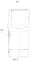
- FIG. 1 is a three-dimensional schematic structural diagram of an atomizer according to an embodiment of present disclosure
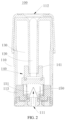
- FIG. 2 is a schematic structural cross-sectional view of an atomizer according to an embodiment of present disclosure
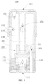
- FIG. 3 is another schematic structural cross-sectional view of an atomizer according to an embodiment of present disclosure
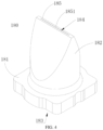
- FIG. 4 is a three-dimensional schematic structural diagram of a one-way valve of an atomizer according to an embodiment of present disclosure.
- an embodiment of present disclosure provides an atomizer 100, and the atomizer includes a housing 110, an airflow channel 120, a liquid-storing chamber 130, a atomization assembly 140, and an air intake valve 150.
- the housing 110 is provided with an air inlet 111 and an air outlet 112, and the airflow channel 120 is formed in the housing 110 and runs through the air inlet 111 and the air outlet 112.
- the liquid-storing chamber 130 is disposed in the housing 110 and stores aerosol-generating material for atomizing of the atomization assembly 140, such as oil.
- the atomization assembly 140 is disposed in the airflow channel 120 and in fluid communication with the liquid-storing chamber 130, so that liquid in the liquid-storing chamber 130 can be supplied to the atomization assembly 140 for the atomization assembly 140 to atomize.
- external air enters from the air inlet 111, carries aerosol formed by the atomization assembly 140 in the airflow channel 120, and flows out of the airflow channel 120 through the air outlet 112.
- the air intake valve 150 is disposed in the airflow channel 120 between the air inlet 111 and the atomization assembly 140, an air outlet portion of the air intake valve 150 is disposed close to the atomization assembly 140, an air inlet portion of the air intake valve 150 is disposed away from the atomization assembly 140, and a leaked liquid storage 151 for storing leaked liquid is formed between the air intake valve 150 and the atomization assembly 140.
- the air intake valve 150 may keep sealed under action of a pressure difference or elasticity of the air intake valve 150.
- the air intake valve 150 could prevent the leaked liquid from polluting and damaging other elements after leaked from the air inlet 111.
- the pressure in the airflow channel 120 is increased, and aerosol reflux may occur.
- the aerosol may flow through the air inlet 111, and run into an outer wall of the atomizer 100, and be condensed into liquid.
- the air intake valve 150 can prevent occurrence of aerosol reflux.
- the housing 110 includes a mounting base 113, the mounting base 113 is configured to support the atomization assembly 140 and the mounting base 113 is configured to define the air inlet 111, and the air inlet 111 and the air outlet 112 are respectively located on two ends of the housing 110.
- the atomization assembly 140 includes a atomization core 141 supported by the mounting base 113 and fixed in the housing 110, one part of the atomization core is located in the airflow channel 120, and the other part of the atomization core is located in the liquid-storing chamber 130.
- the atomization core 141 may be a porous ceramic core, a liquid guiding cotton is covered on a surface of the atomization core, and the liquid guiding cotton absorbs the aerosol-generating material from the liquid-storing chamber 130 to form the aerosol.
- the pressure in the airflow channel 120 is decreased, the air intake valve 150 is opened when the pressure of the air inlet portion of the air intake valve 150 is greater than the pressure in the airflow channel 120 on the air outlet portion by at least 100 pa, and the external air enters the airflow channel 120 through the air intake valve 150.
- the pressure difference between two sides and required for opening the air intake valve 150 may be 200 pa, 500 pa, 1000 pa, 1500 pa, 2000 pa, or higher, and the pressure difference required for opening the air intake valve 150 depends on a structure and a material of the air intake valve 150.
- the air intake valve 150 can not only have a better leakage-proof effect, but also can suck easily for the user.
- the atomizer 100 further includes a gulp valve 160.
- the gulp valve 160 is disposed in the housing 110, an air outlet portion of the gulp valve 160 is located outside the liquid-storing chamber 130, and an air inlet portion of the gulp valve 160 is communicated with the external air.
- the air pressure in the liquid-storing chamber 130 is greater than or equal to the air pressure of the external air, so that the gulp valve 160 may keep sealed under an action of the pressure difference or the elasticity of the gulp valve, to prevent the liquid in the liquid-storing chamber 130 from being leaked through the gulp valve 160.
- the air pressure in the liquid-storing chamber 130 is decreased, and the gulp valve 160 is opened when the pressure on the air inlet portion side of the gulp valve 160 is greater than the pressure in the liquid-storing chamber 130 by at least 100 pa.
- the external air enters the liquid-storing chamber 130 to supplement the air pressure in the liquid-storing chamber 130, so that a situation that the liquid cannot be seeped into the atomization assembly 140 for atomizing due to the excessively low air pressure in the liquid-storing chamber 130 is avoided, thereby the smoothness of the liquid for atomizing is improved.
- the pressure difference between two sides and required for opening the gulp valve 160 may be 200 pa, 500 pa, 1000 pa, 1500 pa, 2000 pa, or higher, and the pressure difference required for opening the gulp valve 160 depends on a structure and a material of the gulp valve 160.
- the air pressure of the air inlet portion of the gulp valve 160 required for opening the gulp valve 160 is greater than the pressure in the liquid-storing chamber 130 on the air outlet portion side by 100 pa to 2000 pa, the gulp valve 160 can supplement the air pressure in the liquid-storing chamber 130 in time, to keep the smoothness of the flowing of liquid from the liquid-storing chamber 130 for atomizing.
- one gulp valve 160 of the three gulp valves is located on the first end provided with the air outlet 112 of the housing 110; one gulp valve 160 of the three gulp valves is located on the second end provided with the air inlet 111 of the housing 110; and one gulp valve 160 of the three gulp valves is located on the side surface between the first end and the second end of the housing 110.
- there may be alternatively two, four, or more gulp valves 160 which is not limited herein.
- the atomizer 100 further includes a mouthpiece valve 170.
- the mouthpiece valve 170 is disposed in the airflow channel 120 and located between the air outlet 112 and the atomization assembly 140, an air outlet portion of the mouthpiece valve 170 faces the air outlet 112, and an air inlet 111 of the mouthpiece valve 170 faces the atomization assembly 140.
- the mouthpiece valve 170 is opened, and after atomizing, the aerosol may flow out from the air outlet 112 through the mouthpiece valve 170.
- the mouthpiece valve 170 is sealed under an action of the elasticity of the mouthpiece valve, further prevent leaked liquid from flowing out from the air outlet 112.
- the mouthpiece valve 170 is opened when pressure of the air inlet portion side of the mouthpiece valve 170 is greater than pressure outside the air outlet portion side of the mouthpiece valve 170 by at least 100 pa.
- the pressure difference between two sides and required for opening the mouthpiece valve 170 may be 200 pa, 500 pa, 1000 pa, 1500 pa, 2000 pa, or higher, and the pressure difference required for opening the mouthpiece valve 170 depends on a structure and a material of the mouthpiece valve 170.
- the mouthpiece valve 170 can not only have a better leakage-proof effect, but also can suck easily for the user.
- the air intake valve 150, the gulp valve 160, and the mouthpiece valve 170 are all one-way valves 180, and the one-way valve 180 includes a base 181 and a deformable wall 182.
- the base 181 is provided with a through hole (not shown in the FIG.s)
- the deformable wall 182 is disposed on the through hole
- the deformable wall 182 is provided with a notch 1851
- one side of the deformable wall 182 connected to the through hole forms an air inlet portion 183
- an air outlet portion 184 is formed at the notch 1851.
- the notch 1851 is closed.
- the pressure of the air inlet portion 183 of the deformable wall 182 is great enough to cause the deformable wall 182 to deform, the notch 1851 is opened, and air flows through the one-way valve 180.
- the deformable wall 182 of the one-way valve 180 includes two first deformable walls, and the two first deformable walls gradually draw close outward through the through hole to form a strip-shaped end 185 and form the elongated notch 1851 at the strip-shaped end 185.
- the one-way valve 180 may have a variety of structures, and details are described below.
- the deformable wall 182 of the one-way valve 180 may be curved to form a cylinder, and the deformable wall 182 is closed to form a hemispherical end 185 extends outward from the through hole and is closed to form the notch 1851 is cross-shaped and formed at the hemispherical end 185, the deformable wall 182 of the cylinder is made by a deformable or a non-deformable material, and the hemispherical end 185 is made by a deformable material.
- the deformable wall 182 of the one-way valve 180 is curved to form a cylinder, and the deformable wall 182 is closed to form a planar end 185 extends outward from the through hole and is closed to form two arc-shaped notches 1851, the notch is cross-shaped 1851 and formed at the planar end 185, and the notch 1851 is in a shape of a inferior arc shaped, the deformable wall 182 of the cylinder is made by a deformable material or a non-deformable material, and the planar end 185 is made by a deformable material.
- the deformable wall 182 of the one-way valve 180 is curved to form a cylinder, and the deformable wall 182 is closed to form a planar end 185 extends outward from the through hole and is closed to form an arc-shaped notch 1851 at the planar end 185, the notch 1851 is in a shape of a major arc, and a support member 1822 for supporting the planar end 185 is disposed in the deformable wall 182, to prevent the planar end 185 from being opened to the side of the air inlet portion 183.
- the deformable wall 182 of the cylinder is made by a deformable or non-deformable material, and the planar end 185 is made by a deformable material.
- the deformable wall 182 of the one-way valve 180 is curved to form a cylinder, and the deformable wall 182 is closed to form a planar end 185 extends outward from the through hole and is closed to form an arc-shaped notch 1851 at the side surface.
- the above mentioned one-way valve 180 of different structures may be selected according to an actual requirement or different using condition.
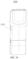
- FIG. 10 is a three-dimensional schematic structural diagram of an electronic atomization device according to an embodiment of present disclosure.
- Another embodiment of present disclosure provides an electronic atomization device 200, including the atomizer 100 in any one of the above mentioned embodiments.
- the electronic atomization device 200 further includes a power supply assembly, and the power supply assembly is configured to supply power to the atomizer 100, so that the atomizer 100 can atomize the aerosol-generating material to form the aerosol.
- the air intake valve 150 is disposed in the airflow channel 120 between the air inlet 111 and the atomization assembly 140, and the leaked liquid storage 151 for storing leaked liquid is formed between the air intake valve 150 and the atomization assembly 140. Therefore, even if liquid in the liquid-storing chamber 130 is leaked through the atomization assembly 140, the liquid can accumulate in the leaked liquid storage 151 rather than being leaked through the air intake valve 150, thereby the air intake valve 150 could preventing the leaked liquid from polluting and damaging other elements after leaked from the air inlet 111. After sucking, the air intake valve 150 can prevent occurrence of aerosol reflux.
- the gulp valve 160 is further disposed in the housing 110.
- the air pressure in the liquid-storing chamber 130 is greater than or equal to the air pressure of the external air, so that the gulp valve 160 may keep sealed under an action of the pressure difference or the elasticity of the gulp valve, to prevent the liquid in the liquid-storing chamber 130 from being leaked through the gulp valve 160.
- the gulp valve 160 can supplement the air pressure in the liquid-storing chamber 130 in time, to keep the smoothness of the flowing of liquid from the liquid-storing chamber 130 for atomizing.
Landscapes
- Engineering & Computer Science (AREA)
- General Engineering & Computer Science (AREA)
- Mechanical Engineering (AREA)
- Containers And Packaging Bodies Having A Special Means To Remove Contents (AREA)
- Filling Or Discharging Of Gas Storage Vessels (AREA)
- Nozzles (AREA)
- Disinfection, Sterilisation Or Deodorisation Of Air (AREA)
Description
- The present disclosure relates to the field of electronic atomization devices, and in particular to an atomizer and an electronic atomization device.
- An existing electronic atomization device includes an atomizer and a controller. The controller includes a battery, a circuit board, and an airflow sensor, and the atomizer includes a liquid-storing chamber storing atomizing materials, a atomization element, and an airflow channel. A vent hole is generally provided at a bottom of the atomizer, so that one end of the airflow channel is communicated to the airflow sensor of the controller, and the airflow sensor can detect the change of the airflow, so that the electronic atomization device may be started. However, during transportating or using, liquid leakage may occur in the liquid-storing chamber of the atomizer due to air pressure changes or other reasons, and the leaking of liquid may enter the controller through the vent hole at the bottom of the atomizer, and the airflow sensor or the battery could easily polluted and damaged.
- Documents
US2019/230986A1 ,US2016/270446A1 ,EP3393278A1 ,US2015/157054A1 ,EP3469937A2 describe electronic atomization devices which describe means for prevention leakage and/or pressure equalisation means. For example,US2019/230986A1 relates to an aerosol-generating device that is configured to reduce and/or minimize leaking of liquid aerosol-forming substrate or condensates, wherein the device may include a housing, a reservoir, an atomizer, and a valve within the mouthpiece of the housing. - This disclosure provides an atomizer and an electronic atomization device, to overcome the technical problem that the atomizer is damaged due to liquid leakage of a liquid-storing chamber of the atomizer.
- In order to overcome the technical problem, a first aspect is provided by the present invention is an atomizer, includes: a housing, provided with an air inlet and an air outlet; an airflow channel, formed in the housing and running through the air inlet and the air outlet; a liquid-storing chamber, disposed in the housing; a atomization assembly, disposed in the airflow channel and in fluid communication with the liquid-storing chamber; an air intake valve, disposed in the airflow channel between the air inlet and the atomization assembly, where an air outlet portion of the air intake valve is disposed close to the atomization assembly, an air inlet portion of the air intake valve is disposed away from the atomization assembly, and a leaked liquid storage for storing leaked liquid is formed between the air intake valve and the atomization assembly; a gulp valve, disposed in the housing, where an air outlet portion of the gulp valve is located in the liquid-storing chamber, and an air inlet portion of the gulp valve is in communication with external air; and a mouthpiece valve, disposed in the airflow channel and located between the air outlet and the atomization assembly, where an air outlet portion of the mouthpiece valve is disposed facing the air outlet, and an air inlet of the mouthpiece valve is disposed facing the atomization assembly.
- According to an embodiment of this disclosure, the air intake valve is opened when pressure of the air inlet portion of the air intake valve is greater than pressure of the air outlet portion of the air intake valve in the airflow channel by at least 100 pa.
- According to an embodiment of this disclosure, the gulp valve is located on a first end provided with the air outlet of the housing; and/or the gulp valve is located on a second end provided with the air inlet of the housing; and/or the gulp valve is located on a side surface between the first end and the second end of the housing.
- According to an embodiment of this disclosure, there are three gulp valves, and the three gulp valves are respectively located on the first end provided with the air outlet of the housing, the second end provided with the air inlet of the housing, and the side surface between the first end and the second end of the housing.
- According to an embodiment of this disclosure, the gulp valve is opened when pressure of the air inlet portion of the gulp valve is greater than pressure in liquid-storing chamber by at least 100 pa.
- According to an embodiment of this disclosure, the mouthpiece valve is opened when pressure of the air inlet portion side of the mouthpiece valve is greater than pressure outside the air outlet portion side of the mouthpiece valve by at least 100 pa.
- According to an embodiment of this disclosure, the air intake valve, the gulp valve, and the mouthpiece valve are all one-way valves, and each of the one-way valve includes: a base, provided with a through hole; and a deformable wall, disposed on the through hole and provided with a notch, where one side of the deformable wall connected to the through hole forms the air inlet portion, and the notch forms the air outlet portion.
- According to an embodiment of this disclosure, the deformable wall includes two first deformable walls, and the two first deformable walls extends outward from the through hole and gradually draw close to each other to form a strip-shaped end and form the notch is elongated and formed at the strip-shaped end.
- According to an embodiment of this disclosure, the deformable wall is curved to form a cylinder, the deformable wall extends outward from the through hole and is closed to form a hemispherical end, and the notch is cross-shaped and formed at the hemispherical end.
- According to an embodiment of this disclosure, the deformable wall is curved to form a cylinder, the deformable wall extends outward from the through hole and is closed to form a planar end, and two notch is arc-shapedes are formed at the planar end, wherein the notch is inferior arc shaped.
- According to an embodiment of this disclosure, the deformable wall is curved to form a cylinder, the deformable wall extends outward from the through hole and is closed to form a planar end, and the notch is arc-shaped and formed at the planar end, wherein the notch is in a shape of a major arc, and a support member supporting the planar end is disposed in the deformable wall.
- According to an embodiment of this disclosure, the deformable wall is curved to form a cylinderr, the deformable wall extends outward from the through hole and is closed to form a planar end, and the notch is arc-shaped and formed at the side surface.
- According to an embodiment of this disclosure, the housing includes a mounting base, and the mounting base is configured to support the atomization assembly and the mounting base is configured to define the air inlet.
- In order to overcome the technical problem, according to a second aspect, an electronic atomization device is provided and includes the atomizer according to any one of above mentioned.
- According to an embodiment of this disclosure, the electronic atomization device includes a power supply assembly configured to supply power to the atomizer.
- Beneficial effects of present disclosure: with the air intake valve of the atomization assembly, even if liquid in the liquid-storing chamber is leaked through the atomization assembly, the liquid can accumulate in the leaked liquid storage rather than being leaked through the air intake valve, thereby the air intake valve could prevent the leaked liquid from polluting and damaging other elements after leaked from the air inlet. In addition, after sucking, the pressure in the airflow channel is increased, and aerosol reflux may occur. In a case without the air intake valve, the aerosol may flow through the air inlet, and run into an outer wall of the atomizer, and be condensed into liquid. However, the air intake valve can prevent occurrence of aerosol reflux.
- In order to more clearly illustrate the technical solutions of the embodiments of the present disclosure, the drawings for the description of the embodiment will be described in brief. Obviously, the drawings in the following description are only some of the embodiments of the present disclosure. For a person of ordinary skill in the art, other drawings may be obtained based on the following drawings without any creative work.
-
FIG. 1 is a three-dimensional schematic structural diagram of an atomizer according to an embodiment of present disclosure; -
FIG. 2 is a schematic structural cross-sectional view of an atomizer according to an embodiment of present disclosure; -
FIG. 3 is another schematic structural cross-sectional view of an atomizer according to an embodiment of present disclosure; -
FIG. 4 is a three-dimensional schematic structural diagram of a one-way valve of an atomizer according to an embodiment of present disclosure; -
FIG. 5 is a three-dimensional schematic structural diagram of a one-way valve of an atomizer according to another embodiment of present disclosure; -
FIG. 6 is a three-dimensional schematic structural diagram of a one-way valve of an atomizer according to still another embodiment of present disclosure; -
FIG. 7 is a three-dimensional schematic structural diagram of a one-way valve of an atomizer according to still another embodiment of present disclosure; -
FIG. 8 is a schematic structural cross-sectional view of the one-way valve shown inFIG. 7 ; -
FIG. 9 is a three-dimensional schematic structural diagram of a one-way valve of an atomizer according to still another embodiment of present disclosure; and -
FIG. 10 is a three-dimensional schematic structural diagram of an electronic atomization device according to an embodiment of present disclosure. - Technical solutions of the embodiments of the present disclosure will be clearly and comprehensively described by referring to the accompanying drawings. Obviously, the embodiments described herein are only a part of, but not all of, the embodiments of the present disclosure. Based on the embodiments in the present disclosure, all other embodiments obtained by a person of ordinary skill in the art without any creative work shall fall within the scope of the present disclosure.
- It should be noted that directional indications if present (such as up, down, left, right, front, back, ......) in the embodiments of the present disclosure are only expressed to explain relative positional relationships and movement between components in a particular attitude (as shown in the drawings). When the particular attitude is changed, the directional indications shall also be changed accordingly.
- In addition, when using expressions "first", "second", and the like in the embodiment of the present disclosure, the expressions "first", "second", and the like are utilized for descriptive purposes only, and shall not be interpreted as indicating or implying relative importance or implicitly specifying the number of an indicated technical feature. Therefore, features defined by "first" and "second" may explicitly or implicitly include at least one of the such feature. In addition, technical solutions of various embodiments may be combined with each other, but only on the basis that the technical solutions may be achieved by a person of ordinary skill in the art. When combination of technical solutions appears to be contradictory or unachievable, such combination of technical solutions shall be interpreted as inexistence and excluded from the scope of the present disclosure.
- The term "comprising" means "including, but not necessarily limited to"; it specifically indicates open-ended inclusion or membership in a so-described combination, group, series and the like. It should be noted that references to "an" or "one" embodiment in present disclosure are not necessarily to the same embodiment, and such references mean at least one. Unless otherwise defined, all technical and scientific terms used herein have the same meaning as a skilled person in the art would understand. The terminology used in the description of the present disclosure is for the purpose of describing particular embodiments and is not intended to limit the disclosure.
- Referring to
FIG. 1 to FIG. 4 ,FIG. 1 is a three-dimensional schematic structural diagram of an atomizer according to an embodiment of present disclosure;FIG. 2 is a schematic structural cross-sectional view of an atomizer according to an embodiment of present disclosure;FIG. 3 is another schematic structural cross-sectional view of an atomizer according to an embodiment of present disclosure; andFIG. 4 is a three-dimensional schematic structural diagram of a one-way valve of an atomizer according to an embodiment of present disclosure. - As shown in
FIG. 1 andFIG. 2 , an embodiment of present disclosure provides anatomizer 100, and the atomizer includes ahousing 110, anairflow channel 120, a liquid-storing chamber 130, aatomization assembly 140, and anair intake valve 150. Thehousing 110 is provided with anair inlet 111 and anair outlet 112, and theairflow channel 120 is formed in thehousing 110 and runs through theair inlet 111 and theair outlet 112. The liquid-storing chamber 130 is disposed in thehousing 110 and stores aerosol-generating material for atomizing of theatomization assembly 140, such as oil. Theatomization assembly 140 is disposed in theairflow channel 120 and in fluid communication with the liquid-storing chamber 130, so that liquid in the liquid-storing chamber 130 can be supplied to theatomization assembly 140 for theatomization assembly 140 to atomize. During sucking, external air enters from theair inlet 111, carries aerosol formed by theatomization assembly 140 in theairflow channel 120, and flows out of theairflow channel 120 through theair outlet 112. - The
air intake valve 150 is disposed in theairflow channel 120 between theair inlet 111 and theatomization assembly 140, an air outlet portion of theair intake valve 150 is disposed close to theatomization assembly 140, an air inlet portion of theair intake valve 150 is disposed away from theatomization assembly 140, and a leakedliquid storage 151 for storing leaked liquid is formed between theair intake valve 150 and theatomization assembly 140. When the atomizer is not in use, since pressure in theairflow channel 120 is greater than or equal to external pressure, theair intake valve 150 may keep sealed under action of a pressure difference or elasticity of theair intake valve 150. Therefore, even if liquid in the liquid-storingchamber 130 is leaked through theatomization assembly 140, the liquid can accumulate in the leakedliquid storage 151 rather than being leaked through theair intake valve 150, thereby theair intake valve 150 could prevent the leaked liquid from polluting and damaging other elements after leaked from theair inlet 111. In addition, after sucking, the pressure in theairflow channel 120 is increased, and aerosol reflux may occur. In a case without theair intake valve 150, the aerosol may flow through theair inlet 111, and run into an outer wall of theatomizer 100, and be condensed into liquid. However, theair intake valve 150 can prevent occurrence of aerosol reflux. - In an embodiment, as shown in
FIG. 2 , thehousing 110 includes a mountingbase 113, the mountingbase 113 is configured to support theatomization assembly 140 and the mountingbase 113 is configured to define theair inlet 111, and theair inlet 111 and theair outlet 112 are respectively located on two ends of thehousing 110. Theatomization assembly 140 includes aatomization core 141 supported by the mountingbase 113 and fixed in thehousing 110, one part of the atomization core is located in theairflow channel 120, and the other part of the atomization core is located in the liquid-storingchamber 130. Theatomization core 141 may be a porous ceramic core, a liquid guiding cotton is covered on a surface of the atomization core, and the liquid guiding cotton absorbs the aerosol-generating material from the liquid-storingchamber 130 to form the aerosol. - In an embodiment, as shown in
FIG. 2 , in operation of theatomizer 100, a user sucks at theair outlet 112, the pressure in theairflow channel 120 is decreased, theair intake valve 150 is opened when the pressure of the air inlet portion of theair intake valve 150 is greater than the pressure in theairflow channel 120 on the air outlet portion by at least 100 pa, and the external air enters theairflow channel 120 through theair intake valve 150. It should be noted that, the pressure difference between two sides and required for opening theair intake valve 150 may be 200 pa, 500 pa, 1000 pa, 1500 pa, 2000 pa, or higher, and the pressure difference required for opening theair intake valve 150 depends on a structure and a material of theair intake valve 150. When the pressure of the air inlet portion of theair intake valve 150 required for opening theair intake valve 150 is greater than the pressure in theairflow channel 120 on the air outlet portion side by 100 pa to 2000 pa, theair intake valve 150 can not only have a better leakage-proof effect, but also can suck easily for the user. - In an embodiment, as shown in
FIG. 3 , theatomizer 100 further includes agulp valve 160. Thegulp valve 160 is disposed in thehousing 110, an air outlet portion of thegulp valve 160 is located outside the liquid-storingchamber 130, and an air inlet portion of thegulp valve 160 is communicated with the external air. Under normal condition, the air pressure in the liquid-storingchamber 130 is greater than or equal to the air pressure of the external air, so that thegulp valve 160 may keep sealed under an action of the pressure difference or the elasticity of the gulp valve, to prevent the liquid in the liquid-storingchamber 130 from being leaked through thegulp valve 160. After the liquid in the liquid-storingchamber 130 is continuously consumed by atomizing of theatomization assembly 140, the air pressure in the liquid-storingchamber 130 is decreased, and thegulp valve 160 is opened when the pressure on the air inlet portion side of thegulp valve 160 is greater than the pressure in the liquid-storingchamber 130 by at least 100 pa. The external air enters the liquid-storingchamber 130 to supplement the air pressure in the liquid-storingchamber 130, so that a situation that the liquid cannot be seeped into theatomization assembly 140 for atomizing due to the excessively low air pressure in the liquid-storingchamber 130 is avoided, thereby the smoothness of the liquid for atomizing is improved. It should be noted that, the pressure difference between two sides and required for opening thegulp valve 160 may be 200 pa, 500 pa, 1000 pa, 1500 pa, 2000 pa, or higher, and the pressure difference required for opening thegulp valve 160 depends on a structure and a material of thegulp valve 160. When the air pressure of the air inlet portion of thegulp valve 160 required for opening thegulp valve 160 is greater than the pressure in the liquid-storingchamber 130 on the air outlet portion side by 100 pa to 2000 pa, thegulp valve 160 can supplement the air pressure in the liquid-storingchamber 130 in time, to keep the smoothness of the flowing of liquid from the liquid-storingchamber 130 for atomizing. - In an embodiment, as shown in
FIG. 3 , there are three gulp valves, onegulp valve 160 of the three gulp valves is located on the first end provided with theair outlet 112 of thehousing 110; onegulp valve 160 of the three gulp valves is located on the second end provided with theair inlet 111 of thehousing 110; and onegulp valve 160 of the three gulp valves is located on the side surface between the first end and the second end of thehousing 110. In other embodiments, there may be only onegulp valve 160, and thegulp valve 160 may be located at any position of the three positions as above mentioned . Alternatively, in other embodiments, there may be alternatively two, four, ormore gulp valves 160, which is not limited herein. - Further more, as shown in
FIG. 3 , theatomizer 100 further includes amouthpiece valve 170. Themouthpiece valve 170 is disposed in theairflow channel 120 and located between theair outlet 112 and theatomization assembly 140, an air outlet portion of themouthpiece valve 170 faces theair outlet 112, and anair inlet 111 of themouthpiece valve 170 faces theatomization assembly 140. During the user sucking, themouthpiece valve 170 is opened, and after atomizing, the aerosol may flow out from theair outlet 112 through themouthpiece valve 170. After sucking, themouthpiece valve 170 is sealed under an action of the elasticity of the mouthpiece valve, further prevent leaked liquid from flowing out from theair outlet 112. Themouthpiece valve 170 is opened when pressure of the air inlet portion side of themouthpiece valve 170 is greater than pressure outside the air outlet portion side of themouthpiece valve 170 by at least 100 pa. It should be noted that, the pressure difference between two sides and required for opening themouthpiece valve 170 may be 200 pa, 500 pa, 1000 pa, 1500 pa, 2000 pa, or higher, and the pressure difference required for opening themouthpiece valve 170 depends on a structure and a material of themouthpiece valve 170. When the pressure of the air inlet portion of themouthpiece valve 170 required for opening themouthpiece valve 170 is greater than the pressure outside the air outlet portion side by 100 pa to 2000 pa, themouthpiece valve 170 can not only have a better leakage-proof effect, but also can suck easily for the user. - In an embodiment, as shown in
FIG. 3 andFIG. 4 , theair intake valve 150, thegulp valve 160, and themouthpiece valve 170 are all one-way valves 180, and the one-way valve 180 includes abase 181 and adeformable wall 182. Thebase 181 is provided with a through hole (not shown in the FIG.s), thedeformable wall 182 is disposed on the through hole, thedeformable wall 182 is provided with anotch 1851, one side of thedeformable wall 182 connected to the through hole forms anair inlet portion 183, and anair outlet portion 184 is formed at thenotch 1851. In a normal case, thenotch 1851 is closed. When the pressure of theair inlet portion 183 of thedeformable wall 182 is great enough to cause thedeformable wall 182 to deform, thenotch 1851 is opened, and air flows through the one-way valve 180. - Specifically, as shown in
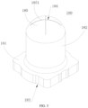
FIG. 4 , thedeformable wall 182 of the one-way valve 180 includes two first deformable walls, and the two first deformable walls gradually draw close outward through the through hole to form a strip-shapedend 185 and form theelongated notch 1851 at the strip-shapedend 185. - In other embodiments, referring to
FIG. 5 to FIG. 9 , the one-way valve 180 may have a variety of structures, and details are described below. - As shown in
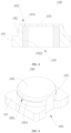
FIG. 5 , thedeformable wall 182 of the one-way valve 180 may be curved to form a cylinder, and thedeformable wall 182 is closed to form ahemispherical end 185 extends outward from the through hole and is closed to form thenotch 1851 is cross-shaped and formed at thehemispherical end 185, thedeformable wall 182 of the cylinder is made by a deformable or a non-deformable material, and thehemispherical end 185 is made by a deformable material. - As shown in
FIG. 6 , thedeformable wall 182 of the one-way valve 180 is curved to form a cylinder, and thedeformable wall 182 is closed to form aplanar end 185 extends outward from the through hole and is closed to form two arc-shapednotches 1851, the notch is cross-shaped 1851 and formed at theplanar end 185, and thenotch 1851 is in a shape of a inferior arc shaped, thedeformable wall 182 of the cylinder is made by a deformable material or a non-deformable material, and theplanar end 185 is made by a deformable material. - As shown in
FIG. 7 andFIG. 8 , thedeformable wall 182 of the one-way valve 180 is curved to form a cylinder, and thedeformable wall 182 is closed to form aplanar end 185 extends outward from the through hole and is closed to form an arc-shapednotch 1851 at theplanar end 185, thenotch 1851 is in a shape of a major arc, and asupport member 1822 for supporting theplanar end 185 is disposed in thedeformable wall 182, to prevent theplanar end 185 from being opened to the side of theair inlet portion 183. Thedeformable wall 182 of the cylinder is made by a deformable or non-deformable material, and theplanar end 185 is made by a deformable material. - As shown in
FIG. 9 , thedeformable wall 182 of the one-way valve 180 is curved to form a cylinder, and thedeformable wall 182 is closed to form aplanar end 185 extends outward from the through hole and is closed to form an arc-shapednotch 1851 at the side surface. - The above mentioned one-
way valve 180 of different structures may be selected according to an actual requirement or different using condition. - Referring to
FIG. 10, FIG. 10 is a three-dimensional schematic structural diagram of an electronic atomization device according to an embodiment of present disclosure. Another embodiment of present disclosure provides anelectronic atomization device 200, including theatomizer 100 in any one of the above mentioned embodiments. Theelectronic atomization device 200 further includes a power supply assembly, and the power supply assembly is configured to supply power to theatomizer 100, so that theatomizer 100 can atomize the aerosol-generating material to form the aerosol. - In conclusion, according to the
atomizer 100 of present disclosure, theair intake valve 150 is disposed in theairflow channel 120 between theair inlet 111 and theatomization assembly 140, and the leakedliquid storage 151 for storing leaked liquid is formed between theair intake valve 150 and theatomization assembly 140. Therefore, even if liquid in the liquid-storingchamber 130 is leaked through theatomization assembly 140, the liquid can accumulate in the leakedliquid storage 151 rather than being leaked through theair intake valve 150, thereby theair intake valve 150 could preventing the leaked liquid from polluting and damaging other elements after leaked from theair inlet 111. After sucking, theair intake valve 150 can prevent occurrence of aerosol reflux. In theatomizer 100 of present disclosure, thegulp valve 160 is further disposed in thehousing 110. Under normal condition, the air pressure in the liquid-storingchamber 130 is greater than or equal to the air pressure of the external air, so that thegulp valve 160 may keep sealed under an action of the pressure difference or the elasticity of the gulp valve, to prevent the liquid in the liquid-storingchamber 130 from being leaked through thegulp valve 160. When the air pressure in the liquid-storingchamber 130 is insufficient, thegulp valve 160 can supplement the air pressure in the liquid-storingchamber 130 in time, to keep the smoothness of the flowing of liquid from the liquid-storingchamber 130 for atomizing. - The above shows only embodiments of the present disclosure, but does not limit the scope of the present disclosure. Any equivalent structure or equivalent process transformation made based on the specification and the accompanying drawings of the present disclosure, applied directly or indirectly in other related arts, shall be included in the scope of the present disclosure.
Claims (15)
- A atomizer (100), comprising:a housing (110), provided with an air inlet (111) and an air outlet (112);an airflow channel (120), formed in the housing (110) and running through the air inlet (111) and the air outlet (112);a liquid-storing chamber (130), disposed in the housing (110);a atomization assembly (140), disposed in the airflow channel (120) and in fluid communication with the liquid-storing chamber (130);an air intake valve (150), disposed in the airflow channel (120) between the air inlet (111) and the atomization assembly (140), wherein an air outlet portion of the air intake valve (150) is disposed close to the atomization assembly (140), an air inlet portion of the air intake valve (150) is disposed away from the atomization assembly (140), and a leaked liquid storage (151) for storing leaked liquid is formed between the air intake valve (150) and the atomization assembly (140);a gulp valve (160), disposed in the housing (110), wherein an air outlet portion of the gulp valve (160) is located in the liquid-storing chamber (130), and an air inlet portion of the gulp valve (160) is communicated with external air; anda mouthpiece valve (170), disposed in the airflow channel (120) and located between the air outlet (112) and the atomization assembly (140), wherein an air outlet portion of the mouthpiece valve (170) faces the air outlet (112), and an air inlet (111) of the mouthpiece valve (170) faces the atomization assembly (140).
- The atomizer (100) of claim 1, wherein the air intake valve (150) is opened when pressure of the air inlet portion side of the air intake valve (150) is greater than pressure in the airflow channel (120) on the air outlet portion side of the air intake valve (150) by at least 100 pa.
- The atomizer (100) of claim 1, wherein the gulp valve (160) is located on a first end provided with the air outlet (112) of the housing (110); and/orthe gulp valve (160) is located on a second end provided with the air inlet (111) of the housing (110); and/orthe gulp valve (160) is located on a side surface between the first end and the second end of the housing (110).
- The atomizer (100) of claim 3, wherein there are three gulp valves, and the three gulp valves are respectively located on the first end provided with the air outlet (112) of the housing (110), the second end provided with the air inlet (111) of the housing (110), and the side surface between the first end and the second end of the housing (110).
- The atomizer (100) of claim 1, wherein the gulp valve (160) is opened when pressure of the air inlet portion side of the gulp valve (160) is greater than pressure in liquid-storing chamber (130) by at least 100 pa.
- The atomizer (100) of claim 1, wherein the mouthpiece valve (170) is opened when pressure of the air inlet portion side of the mouthpiece valve (170) is greater than pressure outside the air outlet portion side of the mouthpiece valve (170) by at least 100 pa.
- The atomizer (100) of claim 1, wherein the air intake valve (150), the gulp valve (160), and the mouthpiece valve (170) are all one-way valves (180), and each of the one-way valves (180) comprises:a base (181), provided with a through hole; anda deformable wall (182), disposed on the through hole and provided with a notch (1851), wherein one side of the deformable wall (182) connected to the through hole forms the air inlet portion, and the notch (1851) forms the air outlet portion.
- The atomizer (100) of claim 7, wherein the deformable wall (182) comprises two first deformable walls, and the two first deformable walls extend outward from the through hole and gradually draw close to each other to form a strip-shaped end (185) and, the notch (1851) is elongated and formed at the strip-shaped end (185).
- The atomizer (100) of claim 7, wherein the deformable wall (182) is curved to form a cylinder, the deformable wall (182) extends outward from the through hole and is closed to form a hemispherical end (185), and the notch (1851) is cross-shaped and formed at the hemispherical end (185).
- The atomizer (100) of claim 7, wherein the deformable wall (182) is curved to form a cylinder, the deformable wall (182) extends outward from the through hole and is closed to form a planar end (185), and two arc-shaped notches are formed at the planar end (185), wherein the notch (1851) is inferior arc shaped.
- The atomizer (100) of claim 7, wherein the deformable wall (182) is curved to form a cylinder, the deformable wall (182) extends outward from the through hole and is closed to form a planar end (185), and the notch (1851) is arc-shaped and formed at the planar end (185), wherein the notch (1851) is in a shape of a major arc, and a support member (1822) supporting the planar end (185) is disposed in the deformable wall (182).
- The atomizer (100) of claim 7, wherein the deformable wall (182) is curved to form a cylinder, the deformable wall (182) extends outward from the through hole and is closed to form a planar end (185), and the notch (1851) is arc-shaped and formed at the side surface.
- The atomizer (100) of any of claims 1 to 12, wherein the housing (110) comprises a mounting base (113), and the mounting base (113) is configured to support the atomization assembly (140) and the mounting base (113) is configured to define the air inlet (111).
- An electronic atomization device (200), comprising the atomizer (100) according to any one of claims 1-13.
- The electronic atomization device (200) of claim 14, comprises
a power supply assembly, configured to supply power to the atomizer (100).
Applications Claiming Priority (2)
| Application Number | Priority Date | Filing Date | Title |
|---|---|---|---|
| CN201922279855.3U CN211746967U (en) | 2019-12-17 | 2019-12-17 | Atomizers and Electronic Atomizers |
| PCT/CN2020/127083 WO2021120919A1 (en) | 2019-12-17 | 2020-11-06 | Atomizer and electronic atomization device |
Publications (3)
| Publication Number | Publication Date |
|---|---|
| EP4074203A1 EP4074203A1 (en) | 2022-10-19 |
| EP4074203A4 EP4074203A4 (en) | 2023-03-01 |
| EP4074203B1 true EP4074203B1 (en) | 2023-12-06 |
Family
ID=72982280
Family Applications (1)
| Application Number | Title | Priority Date | Filing Date |
|---|---|---|---|
| EP20903897.5A Active EP4074203B1 (en) | 2019-12-17 | 2020-11-06 | Atomizer and electronic atomization device |
Country Status (4)
| Country | Link |
|---|---|
| US (1) | US12446627B2 (en) |
| EP (1) | EP4074203B1 (en) |
| CN (1) | CN211746967U (en) |
| WO (1) | WO2021120919A1 (en) |
Families Citing this family (15)
| Publication number | Priority date | Publication date | Assignee | Title |
|---|---|---|---|---|
| CN211746967U (en) * | 2019-12-17 | 2020-10-27 | 深圳麦克韦尔科技有限公司 | Atomizers and Electronic Atomizers |
| WO2021237718A1 (en) | 2020-05-29 | 2021-12-02 | 深圳麦克韦尔科技有限公司 | Atomizer and electronic atomization device |
| US12178254B2 (en) | 2020-06-15 | 2024-12-31 | Shenzhen Smoore Technology Limited | Atomizer and electronic atomization device |
| CN112471608B (en) * | 2020-11-03 | 2024-10-29 | 深圳麦克韦尔科技有限公司 | Atomizing assembly and electronic atomizing device |
| EP4008203B1 (en) * | 2020-12-04 | 2024-10-09 | Shenzhen Eigate Technology Co., Ltd. | Electronic cigarette comprising one-way valve |
| CN114680376A (en) * | 2020-12-25 | 2022-07-01 | 深圳市合元科技有限公司 | Atomizer and electronic atomization device |
| CN113455713A (en) * | 2021-06-23 | 2021-10-01 | 昂纳自动化技术(深圳)有限公司 | Atomizing device capable of supplementing air and electronic cigarette |
| WO2022266891A1 (en) * | 2021-06-23 | 2022-12-29 | 昂纳自动化技术(深圳)有限公司 | Atomization device capable of supplementing air and electronic cigarette |
| CN113615874A (en) * | 2021-08-03 | 2021-11-09 | 深圳市基克纳科技有限公司 | Atomization sealing structure, atomizer and electronic atomization device |
| CN113925230A (en) * | 2021-10-12 | 2022-01-14 | 深圳市吉迩科技有限公司 | Aerosol generating article and aerosol generating system |
| EP4305978A4 (en) * | 2022-04-29 | 2024-07-24 | Shenzhen Huachengda Precision Industry Co., Ltd. | ELECTRONIC ATOMIZER |
| CN114847523A (en) * | 2022-04-29 | 2022-08-05 | 深圳市华诚达精密工业有限公司 | Electronic atomizer |
| WO2024132793A1 (en) * | 2022-12-22 | 2024-06-27 | Jt International Sa | An aerosol generation device |
| WO2024218809A1 (en) * | 2023-04-17 | 2024-10-24 | 日本たばこ産業株式会社 | Flavor-generating article and smoking system |
| CN220654768U (en) * | 2023-08-15 | 2024-03-26 | 爱奇迹(香港)有限公司 | Atomizing subassembly and atomizing equipment |
Family Cites Families (15)
| Publication number | Priority date | Publication date | Assignee | Title |
|---|---|---|---|---|
| US5483854A (en) * | 1995-03-06 | 1996-01-16 | K2 Development Corporation | Apparatus for removing cork and stoppering structure from pressurized bottle |
| CN204409583U (en) * | 2012-09-28 | 2015-06-24 | 惠州市吉瑞科技有限公司 | Electronic cigarette and electronic cigarette device thereof |
| US10617148B2 (en) * | 2014-11-03 | 2020-04-14 | Philter Labs Incorporated | E-cigarette with valve allowing exhale filter |
| WO2015149313A1 (en) * | 2014-04-02 | 2015-10-08 | 吉瑞高新科技股份有限公司 | Atomization assembly and electronic cigarette |
| WO2016065532A1 (en) | 2014-10-28 | 2016-05-06 | 惠州市吉瑞科技有限公司 | Electronic cigarette |
| CN108289510B (en) * | 2015-12-22 | 2021-02-19 | 菲利普莫里斯生产公司 | Electrically operated aerosol-generating system with liquid pump |
| CN105768233B (en) * | 2016-04-28 | 2019-01-04 | 深圳市新宜康科技股份有限公司 | One-way ventilating electronic cigarette atomizing core |
| CN206213284U (en) * | 2016-11-22 | 2017-06-06 | 深圳市赛尔美电子科技有限公司 | Electronic atomizer |
| CN207011690U (en) * | 2017-07-17 | 2018-02-16 | 湖南中烟工业有限责任公司 | A kind of electronic smoke atomizer |
| CN207855035U (en) * | 2017-12-25 | 2018-09-14 | 上海新型烟草制品研究院有限公司 | A kind of atomizing component and electronic cigarette |
| JP7752475B2 (en) * | 2018-01-30 | 2025-10-10 | フィリップ・モーリス・プロダクツ・ソシエテ・アノニム | Leak-reduced aerosol generator |
| CN207870276U (en) * | 2018-02-09 | 2018-09-18 | 深圳市合元科技有限公司 | A kind of atomizer and electronic cigarette |
| CN120226799A (en) * | 2018-06-07 | 2025-07-01 | 尤尔实验室有限公司 | Cartridges for evaporator devices |
| GB2576298B (en) * | 2018-06-29 | 2022-06-22 | Nicoventures Trading Ltd | Vapour Provision Device |
| CN211746967U (en) * | 2019-12-17 | 2020-10-27 | 深圳麦克韦尔科技有限公司 | Atomizers and Electronic Atomizers |
-
2019
- 2019-12-17 CN CN201922279855.3U patent/CN211746967U/en active Active
-
2020
- 2020-11-06 EP EP20903897.5A patent/EP4074203B1/en active Active
- 2020-11-06 WO PCT/CN2020/127083 patent/WO2021120919A1/en not_active Ceased
-
2022
- 2022-06-14 US US17/840,048 patent/US12446627B2/en active Active
Also Published As
| Publication number | Publication date |
|---|---|
| WO2021120919A1 (en) | 2021-06-24 |
| US12446627B2 (en) | 2025-10-21 |
| EP4074203A4 (en) | 2023-03-01 |
| US20220304391A1 (en) | 2022-09-29 |
| EP4074203A1 (en) | 2022-10-19 |
| CN211746967U (en) | 2020-10-27 |
Similar Documents
| Publication | Publication Date | Title |
|---|---|---|
| EP4074203A1 (en) | Atomizer and electronic atomization device | |
| EP4151099B1 (en) | Atomization device | |
| CN114158774B (en) | Electronic atomization device and atomizer | |
| CN112189897B (en) | Atomizer and electronic atomization device thereof | |
| EP4378332A1 (en) | Atomizer and aerosol generating device | |
| MY205447A (en) | A cartridge for an aerosol-generating system | |
| EP2103435A3 (en) | Liquid delivery system and manufacturing method for the same | |
| US9566400B2 (en) | Nebulizer with negative pressure structure | |
| AR051769A1 (en) | A LIQUID SENSOR IN A LIQUID CONTAINER USED TO SUPPLY A LIQUID TO AN APPLIANCE CONSUMING LIQUIDS, AND A LIQUID CONTAINER IN WHICH THE LIQUID SENSOR IS INCORPORATED | |
| MY146482A (en) | Liquid material discharge device with debubbling mechanism | |
| US9700907B2 (en) | Discharging device | |
| CN114762538B (en) | Electronic atomizing device and atomizer thereof | |
| CN113197352A (en) | An electronic atomization device | |
| CN212911674U (en) | Electronic atomization device | |
| CN219556328U (en) | Electronic atomizing device and atomizer thereof | |
| CN217487646U (en) | Atomization components and electronic atomization devices | |
| CN216459525U (en) | Electronic atomizing device, power supply assembly and bracket thereof | |
| CN218219162U (en) | Electronic atomization device | |
| CN221241700U (en) | Atomizer and electronic atomization device | |
| CN221330260U (en) | Atomization components and atomization devices | |
| CN115067559B (en) | Electronic atomizing devices and their atomizers | |
| CN115005509A (en) | Electronic atomization device | |
| CN114098162A (en) | An electronic atomization device | |
| CN219982150U (en) | Electronic atomizing device | |
| CN223568722U (en) | Liquid storage bin and atomization device |
Legal Events
| Date | Code | Title | Description |
|---|---|---|---|
| STAA | Information on the status of an ep patent application or granted ep patent |
Free format text: STATUS: THE INTERNATIONAL PUBLICATION HAS BEEN MADE |
|
| PUAI | Public reference made under article 153(3) epc to a published international application that has entered the european phase |
Free format text: ORIGINAL CODE: 0009012 |
|
| STAA | Information on the status of an ep patent application or granted ep patent |
Free format text: STATUS: REQUEST FOR EXAMINATION WAS MADE |
|
| 17P | Request for examination filed |
Effective date: 20220709 |
|
| AK | Designated contracting states |
Kind code of ref document: A1 Designated state(s): AL AT BE BG CH CY CZ DE DK EE ES FI FR GB GR HR HU IE IS IT LI LT LU LV MC MK MT NL NO PL PT RO RS SE SI SK SM TR |
|
| REG | Reference to a national code |
Ref country code: DE Ref legal event code: R079 Free format text: PREVIOUS MAIN CLASS: A24F0047000000 Ipc: A24F0040485000 Ref document number: 602020022495 Country of ref document: DE |
|
| A4 | Supplementary search report drawn up and despatched |
Effective date: 20230127 |
|
| RIC1 | Information provided on ipc code assigned before grant |
Ipc: A24F 40/40 20200101ALI20230123BHEP Ipc: A24F 40/10 20200101ALI20230123BHEP Ipc: A24F 40/485 20200101AFI20230123BHEP |
|
| DAV | Request for validation of the european patent (deleted) | ||
| DAX | Request for extension of the european patent (deleted) | ||
| GRAP | Despatch of communication of intention to grant a patent |
Free format text: ORIGINAL CODE: EPIDOSNIGR1 |
|
| STAA | Information on the status of an ep patent application or granted ep patent |
Free format text: STATUS: GRANT OF PATENT IS INTENDED |
|
| RIC1 | Information provided on ipc code assigned before grant |
Ipc: A24F 40/40 20200101ALN20230706BHEP Ipc: A24F 40/10 20200101ALN20230706BHEP Ipc: A24F 40/485 20200101AFI20230706BHEP |
|
| INTG | Intention to grant announced |
Effective date: 20230731 |
|
| GRAS | Grant fee paid |
Free format text: ORIGINAL CODE: EPIDOSNIGR3 |
|
| GRAA | (expected) grant |
Free format text: ORIGINAL CODE: 0009210 |
|
| STAA | Information on the status of an ep patent application or granted ep patent |
Free format text: STATUS: THE PATENT HAS BEEN GRANTED |
|
| P01 | Opt-out of the competence of the unified patent court (upc) registered |
Effective date: 20231004 |
|
| AK | Designated contracting states |
Kind code of ref document: B1 Designated state(s): AL AT BE BG CH CY CZ DE DK EE ES FI FR GB GR HR HU IE IS IT LI LT LU LV MC MK MT NL NO PL PT RO RS SE SI SK SM TR |
|
| REG | Reference to a national code |
Ref country code: GB Ref legal event code: FG4D |
|
| REG | Reference to a national code |
Ref country code: CH Ref legal event code: EP |
|
| REG | Reference to a national code |
Ref country code: DE Ref legal event code: R096 Ref document number: 602020022495 Country of ref document: DE |
|
| REG | Reference to a national code |
Ref country code: IE Ref legal event code: FG4D |
|
| REG | Reference to a national code |
Ref country code: LT Ref legal event code: MG9D |
|
| PG25 | Lapsed in a contracting state [announced via postgrant information from national office to epo] |
Ref country code: GR Free format text: LAPSE BECAUSE OF FAILURE TO SUBMIT A TRANSLATION OF THE DESCRIPTION OR TO PAY THE FEE WITHIN THE PRESCRIBED TIME-LIMIT Effective date: 20240307 |
|
| REG | Reference to a national code |
Ref country code: NL Ref legal event code: MP Effective date: 20231206 |
|
| PG25 | Lapsed in a contracting state [announced via postgrant information from national office to epo] |
Ref country code: LT Free format text: LAPSE BECAUSE OF FAILURE TO SUBMIT A TRANSLATION OF THE DESCRIPTION OR TO PAY THE FEE WITHIN THE PRESCRIBED TIME-LIMIT Effective date: 20231206 |
|
| PG25 | Lapsed in a contracting state [announced via postgrant information from national office to epo] |
Ref country code: ES Free format text: LAPSE BECAUSE OF FAILURE TO SUBMIT A TRANSLATION OF THE DESCRIPTION OR TO PAY THE FEE WITHIN THE PRESCRIBED TIME-LIMIT Effective date: 20231206 |
|
| PG25 | Lapsed in a contracting state [announced via postgrant information from national office to epo] |
Ref country code: LT Free format text: LAPSE BECAUSE OF FAILURE TO SUBMIT A TRANSLATION OF THE DESCRIPTION OR TO PAY THE FEE WITHIN THE PRESCRIBED TIME-LIMIT Effective date: 20231206 Ref country code: GR Free format text: LAPSE BECAUSE OF FAILURE TO SUBMIT A TRANSLATION OF THE DESCRIPTION OR TO PAY THE FEE WITHIN THE PRESCRIBED TIME-LIMIT Effective date: 20240307 Ref country code: ES Free format text: LAPSE BECAUSE OF FAILURE TO SUBMIT A TRANSLATION OF THE DESCRIPTION OR TO PAY THE FEE WITHIN THE PRESCRIBED TIME-LIMIT Effective date: 20231206 Ref country code: BG Free format text: LAPSE BECAUSE OF FAILURE TO SUBMIT A TRANSLATION OF THE DESCRIPTION OR TO PAY THE FEE WITHIN THE PRESCRIBED TIME-LIMIT Effective date: 20240306 |
|
| REG | Reference to a national code |
Ref country code: AT Ref legal event code: MK05 Ref document number: 1637535 Country of ref document: AT Kind code of ref document: T Effective date: 20231206 |
|
| PG25 | Lapsed in a contracting state [announced via postgrant information from national office to epo] |
Ref country code: NL Free format text: LAPSE BECAUSE OF FAILURE TO SUBMIT A TRANSLATION OF THE DESCRIPTION OR TO PAY THE FEE WITHIN THE PRESCRIBED TIME-LIMIT Effective date: 20231206 |
|
| PG25 | Lapsed in a contracting state [announced via postgrant information from national office to epo] |
Ref country code: SE Free format text: LAPSE BECAUSE OF FAILURE TO SUBMIT A TRANSLATION OF THE DESCRIPTION OR TO PAY THE FEE WITHIN THE PRESCRIBED TIME-LIMIT Effective date: 20231206 Ref country code: RS Free format text: LAPSE BECAUSE OF FAILURE TO SUBMIT A TRANSLATION OF THE DESCRIPTION OR TO PAY THE FEE WITHIN THE PRESCRIBED TIME-LIMIT Effective date: 20231206 Ref country code: NO Free format text: LAPSE BECAUSE OF FAILURE TO SUBMIT A TRANSLATION OF THE DESCRIPTION OR TO PAY THE FEE WITHIN THE PRESCRIBED TIME-LIMIT Effective date: 20240306 Ref country code: NL Free format text: LAPSE BECAUSE OF FAILURE TO SUBMIT A TRANSLATION OF THE DESCRIPTION OR TO PAY THE FEE WITHIN THE PRESCRIBED TIME-LIMIT Effective date: 20231206 Ref country code: LV Free format text: LAPSE BECAUSE OF FAILURE TO SUBMIT A TRANSLATION OF THE DESCRIPTION OR TO PAY THE FEE WITHIN THE PRESCRIBED TIME-LIMIT Effective date: 20231206 Ref country code: HR Free format text: LAPSE BECAUSE OF FAILURE TO SUBMIT A TRANSLATION OF THE DESCRIPTION OR TO PAY THE FEE WITHIN THE PRESCRIBED TIME-LIMIT Effective date: 20231206 |
|
| PG25 | Lapsed in a contracting state [announced via postgrant information from national office to epo] |
Ref country code: IS Free format text: LAPSE BECAUSE OF FAILURE TO SUBMIT A TRANSLATION OF THE DESCRIPTION OR TO PAY THE FEE WITHIN THE PRESCRIBED TIME-LIMIT Effective date: 20240406 |
|
| PG25 | Lapsed in a contracting state [announced via postgrant information from national office to epo] |
Ref country code: CZ Free format text: LAPSE BECAUSE OF FAILURE TO SUBMIT A TRANSLATION OF THE DESCRIPTION OR TO PAY THE FEE WITHIN THE PRESCRIBED TIME-LIMIT Effective date: 20231206 Ref country code: AT Free format text: LAPSE BECAUSE OF FAILURE TO SUBMIT A TRANSLATION OF THE DESCRIPTION OR TO PAY THE FEE WITHIN THE PRESCRIBED TIME-LIMIT Effective date: 20231206 |
|
| PG25 | Lapsed in a contracting state [announced via postgrant information from national office to epo] |
Ref country code: SK Free format text: LAPSE BECAUSE OF FAILURE TO SUBMIT A TRANSLATION OF THE DESCRIPTION OR TO PAY THE FEE WITHIN THE PRESCRIBED TIME-LIMIT Effective date: 20231206 |
|
| PG25 | Lapsed in a contracting state [announced via postgrant information from national office to epo] |
Ref country code: SM Free format text: LAPSE BECAUSE OF FAILURE TO SUBMIT A TRANSLATION OF THE DESCRIPTION OR TO PAY THE FEE WITHIN THE PRESCRIBED TIME-LIMIT Effective date: 20231206 Ref country code: SK Free format text: LAPSE BECAUSE OF FAILURE TO SUBMIT A TRANSLATION OF THE DESCRIPTION OR TO PAY THE FEE WITHIN THE PRESCRIBED TIME-LIMIT Effective date: 20231206 Ref country code: RO Free format text: LAPSE BECAUSE OF FAILURE TO SUBMIT A TRANSLATION OF THE DESCRIPTION OR TO PAY THE FEE WITHIN THE PRESCRIBED TIME-LIMIT Effective date: 20231206 Ref country code: IT Free format text: LAPSE BECAUSE OF FAILURE TO SUBMIT A TRANSLATION OF THE DESCRIPTION OR TO PAY THE FEE WITHIN THE PRESCRIBED TIME-LIMIT Effective date: 20231206 Ref country code: IS Free format text: LAPSE BECAUSE OF FAILURE TO SUBMIT A TRANSLATION OF THE DESCRIPTION OR TO PAY THE FEE WITHIN THE PRESCRIBED TIME-LIMIT Effective date: 20240406 Ref country code: EE Free format text: LAPSE BECAUSE OF FAILURE TO SUBMIT A TRANSLATION OF THE DESCRIPTION OR TO PAY THE FEE WITHIN THE PRESCRIBED TIME-LIMIT Effective date: 20231206 Ref country code: CZ Free format text: LAPSE BECAUSE OF FAILURE TO SUBMIT A TRANSLATION OF THE DESCRIPTION OR TO PAY THE FEE WITHIN THE PRESCRIBED TIME-LIMIT Effective date: 20231206 Ref country code: AT Free format text: LAPSE BECAUSE OF FAILURE TO SUBMIT A TRANSLATION OF THE DESCRIPTION OR TO PAY THE FEE WITHIN THE PRESCRIBED TIME-LIMIT Effective date: 20231206 |
|
| PG25 | Lapsed in a contracting state [announced via postgrant information from national office to epo] |
Ref country code: PT Free format text: LAPSE BECAUSE OF FAILURE TO SUBMIT A TRANSLATION OF THE DESCRIPTION OR TO PAY THE FEE WITHIN THE PRESCRIBED TIME-LIMIT Effective date: 20240408 Ref country code: PL Free format text: LAPSE BECAUSE OF FAILURE TO SUBMIT A TRANSLATION OF THE DESCRIPTION OR TO PAY THE FEE WITHIN THE PRESCRIBED TIME-LIMIT Effective date: 20231206 |
|
| PG25 | Lapsed in a contracting state [announced via postgrant information from national office to epo] |
Ref country code: PT Free format text: LAPSE BECAUSE OF FAILURE TO SUBMIT A TRANSLATION OF THE DESCRIPTION OR TO PAY THE FEE WITHIN THE PRESCRIBED TIME-LIMIT Effective date: 20240408 Ref country code: PL Free format text: LAPSE BECAUSE OF FAILURE TO SUBMIT A TRANSLATION OF THE DESCRIPTION OR TO PAY THE FEE WITHIN THE PRESCRIBED TIME-LIMIT Effective date: 20231206 |
|
| REG | Reference to a national code |
Ref country code: DE Ref legal event code: R097 Ref document number: 602020022495 Country of ref document: DE |
|
| PG25 | Lapsed in a contracting state [announced via postgrant information from national office to epo] |
Ref country code: DK Free format text: LAPSE BECAUSE OF FAILURE TO SUBMIT A TRANSLATION OF THE DESCRIPTION OR TO PAY THE FEE WITHIN THE PRESCRIBED TIME-LIMIT Effective date: 20231206 |
|
| PLBE | No opposition filed within time limit |
Free format text: ORIGINAL CODE: 0009261 |
|
| STAA | Information on the status of an ep patent application or granted ep patent |
Free format text: STATUS: NO OPPOSITION FILED WITHIN TIME LIMIT |
|
| PG25 | Lapsed in a contracting state [announced via postgrant information from national office to epo] |
Ref country code: SI Free format text: LAPSE BECAUSE OF FAILURE TO SUBMIT A TRANSLATION OF THE DESCRIPTION OR TO PAY THE FEE WITHIN THE PRESCRIBED TIME-LIMIT Effective date: 20231206 |
|
| PG25 | Lapsed in a contracting state [announced via postgrant information from national office to epo] |
Ref country code: SI Free format text: LAPSE BECAUSE OF FAILURE TO SUBMIT A TRANSLATION OF THE DESCRIPTION OR TO PAY THE FEE WITHIN THE PRESCRIBED TIME-LIMIT Effective date: 20231206 Ref country code: DK Free format text: LAPSE BECAUSE OF FAILURE TO SUBMIT A TRANSLATION OF THE DESCRIPTION OR TO PAY THE FEE WITHIN THE PRESCRIBED TIME-LIMIT Effective date: 20231206 |
|
| RAP4 | Party data changed (patent owner data changed or rights of a patent transferred) |
Owner name: SHENZHEN SMOORE TECHNOLOGY LIMITED |
|
| 26N | No opposition filed |
Effective date: 20240909 |
|
| REG | Reference to a national code |
Ref country code: DE Ref legal event code: R119 Ref document number: 602020022495 Country of ref document: DE |
|
| REG | Reference to a national code |
Ref country code: CH Ref legal event code: PL |
|
| PG25 | Lapsed in a contracting state [announced via postgrant information from national office to epo] |
Ref country code: MC Free format text: LAPSE BECAUSE OF FAILURE TO SUBMIT A TRANSLATION OF THE DESCRIPTION OR TO PAY THE FEE WITHIN THE PRESCRIBED TIME-LIMIT Effective date: 20231206 |
|
| PG25 | Lapsed in a contracting state [announced via postgrant information from national office to epo] |
Ref country code: LU Free format text: LAPSE BECAUSE OF NON-PAYMENT OF DUE FEES Effective date: 20241106 |
|
| REG | Reference to a national code |
Ref country code: CH Ref legal event code: PL |
|
| PG25 | Lapsed in a contracting state [announced via postgrant information from national office to epo] |
Ref country code: CH Free format text: LAPSE BECAUSE OF NON-PAYMENT OF DUE FEES Effective date: 20241130 |
|
| REG | Reference to a national code |
Ref country code: BE Ref legal event code: MM Effective date: 20241130 |
|
| PG25 | Lapsed in a contracting state [announced via postgrant information from national office to epo] |
Ref country code: FI Free format text: LAPSE BECAUSE OF FAILURE TO SUBMIT A TRANSLATION OF THE DESCRIPTION OR TO PAY THE FEE WITHIN THE PRESCRIBED TIME-LIMIT Effective date: 20231207 |
|
| PG25 | Lapsed in a contracting state [announced via postgrant information from national office to epo] |
Ref country code: DE Free format text: LAPSE BECAUSE OF NON-PAYMENT OF DUE FEES Effective date: 20250603 |
|
| PG25 | Lapsed in a contracting state [announced via postgrant information from national office to epo] |
Ref country code: BE Free format text: LAPSE BECAUSE OF NON-PAYMENT OF DUE FEES Effective date: 20241130 |
|
| PG25 | Lapsed in a contracting state [announced via postgrant information from national office to epo] |
Ref country code: FR Free format text: LAPSE BECAUSE OF NON-PAYMENT OF DUE FEES Effective date: 20241130 |
|
| PGFP | Annual fee paid to national office [announced via postgrant information from national office to epo] |
Ref country code: GB Payment date: 20251126 Year of fee payment: 6 |
|
| PGFP | Annual fee paid to national office [announced via postgrant information from national office to epo] |
Ref country code: IE Payment date: 20251021 Year of fee payment: 6 |
|
| PG25 | Lapsed in a contracting state [announced via postgrant information from national office to epo] |
Ref country code: HU Free format text: LAPSE BECAUSE OF FAILURE TO SUBMIT A TRANSLATION OF THE DESCRIPTION OR TO PAY THE FEE WITHIN THE PRESCRIBED TIME-LIMIT; INVALID AB INITIO Effective date: 20201106 |
|
| PG25 | Lapsed in a contracting state [announced via postgrant information from national office to epo] |
Ref country code: CY Free format text: LAPSE BECAUSE OF FAILURE TO SUBMIT A TRANSLATION OF THE DESCRIPTION OR TO PAY THE FEE WITHIN THE PRESCRIBED TIME-LIMIT; INVALID AB INITIO Effective date: 20201106 |