EP4073608B1 - Verfahren zur genauen und effizienten steuerung von automatisierten geführten fahrzeugen für lasttransportaufgaben - Google Patents
Verfahren zur genauen und effizienten steuerung von automatisierten geführten fahrzeugen für lasttransportaufgaben Download PDFInfo
- Publication number
- EP4073608B1 EP4073608B1 EP19828647.8A EP19828647A EP4073608B1 EP 4073608 B1 EP4073608 B1 EP 4073608B1 EP 19828647 A EP19828647 A EP 19828647A EP 4073608 B1 EP4073608 B1 EP 4073608B1
- Authority
- EP
- European Patent Office
- Prior art keywords
- agv
- velocity
- vehicle
- path
- control
- Prior art date
- Legal status (The legal status is an assumption and is not a legal conclusion. Google has not performed a legal analysis and makes no representation as to the accuracy of the status listed.)
- Active
Links
Images


Classifications
-
- G—PHYSICS
- G05—CONTROLLING; REGULATING
- G05D—SYSTEMS FOR CONTROLLING OR REGULATING NON-ELECTRIC VARIABLES
- G05D1/00—Control of position, course, altitude or attitude of land, water, air or space vehicles, e.g. using automatic pilots
- G05D1/02—Control of position or course in two dimensions
- G05D1/021—Control of position or course in two dimensions specially adapted to land vehicles
- G05D1/0212—Control of position or course in two dimensions specially adapted to land vehicles with means for defining a desired trajectory
- G05D1/0223—Control of position or course in two dimensions specially adapted to land vehicles with means for defining a desired trajectory involving speed control of the vehicle
-
- B—PERFORMING OPERATIONS; TRANSPORTING
- B62—LAND VEHICLES FOR TRAVELLING OTHERWISE THAN ON RAILS
- B62D—MOTOR VEHICLES; TRAILERS
- B62D15/00—Steering not otherwise provided for
- B62D15/02—Steering position indicators ; Steering position determination; Steering aids
- B62D15/025—Active steering aids, e.g. helping the driver by actively influencing the steering system after environment evaluation
Definitions
- the present invention belongs to the technical field of controlling position or course in two dimensions specially adapted to land vehicles along the already precomputed path involving the speed control of the vehicle. More specifically, the said vehicle control includes, inter alia, control over vehicles with multiple actuated wheels, with the provision to explicitly avoid wheel slippage and ensures that velocity and acceleration constraints along the said path are respected.
- AGVs Automated Guided Vehicles
- Efficiency (item 5) is often sacrificed, i.e., the vehicles are not being used to their full potential.
- maximum vehicle velocities on curved segments are often artificially reduced to maintain the required accuracy. So, the focus of the present invention is to unlock the velocity potentials of the AGVs by the proposed method.
- the presented method solves the problem of computing the required steering and velocity input signals which drive an autonomous vehicle safely and accurately along the desired path. It runs in real-time on standard industrial hardware providing significantly better accuracy at higher velocities and when making turns, compared to state-of-the-art control systems. It explicitly takes into account the vehicle kinematic model and constraints, providing optimal control signals without extensive parameter tuning. Finally, it optimizes path traversal times enabling maximum vehicle utilization.
- the cited document discloses a similar approach as disclosed with this invention, but without performing an adaptation of the sampling time by taking into account the actual AGV speed and the actual prediction horizon length. Such an approach would reduce the position error of the said AVG, while driving for instance at low speed and it would concurrently allow for optimization of the calculation load, carried by the on-board processing unit.
- the present invention discloses a control method for automated guided vehicles (AGV), where said AGV is equipped with:
- the disclosed method consists of the following steps where said method:
- the adaptive sampling in step i) is performed by using Bezier curves.
- step iii) said method takes into account a first-order lag of wheel velocity responses and first or second order lag of wheel steering responses which is relevant for ensuring good tracking, as well as the external velocity limit control; the resulting trajectory for each separate wheel minimizes the total travel time by adjusting the actuator traction velocity and steering setpoints in a continuous manner while achieving the imposed vehicle velocity limits per path segments.
- step vi) avoids undesired wheel interaction which leads to some of the wheels blocking or slipping.
- An automated guided vehicle comprising means for carrying out the method as described above is disclosed.
- the invention discloses a control method for automated guided vehicles (AGV).
- AGV automated guided vehicles
- said AGV is equipped with:
- a processing unit which is capable to execute said control method steps; e.g. to control the AGV's actuators, optionally brakes and receive the signals generated by the AGV sensors, which can be located outside of the AGV but connected wirelessly or via cabling in order to perform the desired task in a reliable manner.
- the processing unit can be integrated with the AGV which is the preferred solution.
- the processing unit is a standard computer, e.g., industrial hardware, with appropriate inputs-outputs linked with the said AGV motion control parts. The person skilled in the art will immediately recognize the requirements said processing unit should satisfy in order to be reliably connected with the AGV's actuators and, optionally, the brakes.
- the presented method solves the problem of computing the required steering and velocity input signals which drive an autonomous vehicle safely and accurately along the desired path. It runs in real-time on standard industrial hardware and explicitly takes into account the vehicle kinematic model and constraints, providing optimal control signals without extensive parameter tuning. Finally, the said method optimizes path traversal times enabling maximum vehicle utilization.
- the method assumes a typical AGV navigation scenario, depicted in Figures 2 , 3A and 3B , a vehicle with two actuated wheels - front and rear (subscript f and r ) both with two degrees of freedom - steering and traction - moving along a designated fixed path.
- Wheels are defined with their pose in respect to the AGV's tracking point, given by their offset along vehicle x-y axes and mounting angles ⁇ f and ⁇ r .
- Steering angle of each wheel is denoted by ⁇ and the traction by velocity v .
- This is a generic kinematic model which is applicable to all vehicles without wheel steering offset, i.e., whose wheel steering axis is coincident with wheel traction contact point.
- the presented method can analogously be adapted for vehicles with different number of actuated wheels. Differential drive vehicles and vehicles with Ackermann steering geometry are defined with corresponding mode of motion and actuated wheel limitations.
- the AGV's angle ⁇ AGV depicts the inclination of vehicle reference frame with respect to the x - y coordinates fixed to the environment, i.e., the rotation of vehicle-fixed coordinate system (denoted by the superscript AGV in the rest of the document) with respect to the world-fixed coordinate system (denoted by the superscript w in the rest of the document).
- the vehicle reference frame is centered on the vehicle tracking point which can be an arbitrarily selected point on vehicle.
- R ( ⁇ AGV ) is the rotation matrix from the vehicle-fixed frame to the world-fixed coordinate frame.
- H is the velocity Jacobian matrix linking wheel speed to vehicle tracking point speed, measured with respect to the world-fixed frame and expressed in the vehicle-fixed coordinate frame.
- the model is derived according to the methodology outlined in the reference below:
- AGV velocities are an order of magnitude lower than road vehicle velocities, maximum velocities are typically up to 2 m/s and masses are much larger - payloads vary by industry from 1000 kg to over 100 tones.
- This kinematic model describes AGVs in typical operating conditions with sufficient accuracy without unnecessary computational complexity.
- optimized output sequence is superimposed on the reference trajectory input, yielding actuator setpoints which drive the vehicle state along the reference trajectory.
- C ( u ) [ x ⁇ AGV ( u ) ⁇ AGV ( u )] T with the corresponding mode of motion and maximum vehicle speed assigned to each segment due to traffic or other safety reasons.
- the superscript segment will be used to denote this value, i.e., v segment .
- kinematic configurations which can be defined as a function ⁇ AGV ( u ) which describes the evolution of vehicle nominal orientation along segment C ( u ).
- ⁇ AGV u atan y ⁇ ⁇ AGV u x ⁇ ⁇ AGV u
- Nominal heading of the vehicle ⁇ AGV ( u ), which denotes direction in which the vehicle tracking point moves in world-fixed frame, is always aligned with the path tangent: ⁇ ⁇ AGV u atan y ⁇ ⁇ AGV u x ⁇ ⁇ AGV u
- nominal position of a wheel is defined as a function C w ( u ), i.e., a path that each actuated wheel traverses:
- C w u C u + R ⁇ ⁇ AGV u r w AGV
- the disclosed method is divided in steps described below.
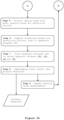
- Step 1 - performs adaptive sampling of the path segments expressed as a parametric curve C ( u ) to identify critical velocity points, characterized by highly non-linear steering dynamics.
- the adaptive sampling is performed as explained, for instance, in the reference:
- path segments C ( u ) are defined as Bezier curves, but the above approach is equally adaptable to any parametrically defined curve.
- Step 1 ends with performed adaptive sampling of the path segments C ( u ) to avoid needless sampling of sufficiently linear segments and identifies initial critical velocity profile points sequence U for the next step.
- step 1 inserts additional samples into the ordered critical velocity points sequence U where step 1 had failed to address the traction velocity limit v w ⁇ u non-linearity.
- any other wheel traction and steering velocity limit, or vehicle linear and angular velocity limit can be analogously appended into the equation (19) by calculating its ratio with nominal vehicle velocity ⁇ AGV ( u ).
- Step 2 ends with a finalized ordered sequence U of critical velocity points, that completely describes velocity limit profile non-linearity while avoiding needless sampling density of path segment C ( u ), and computed corresponding velocity limits sequence L which can be transformed to specific wheel traction velocity by equation (17).
- Step 3 plans optimal traction velocity and steering angle profiles for each of the wheels, i.e., nominal traction velocity setpoint v w ( u ) and nominal steering setpoint ⁇ w ( u ).
- the method disclosed herein optimizes the efficiency of computation by utilizing adaptively sampled critical velocity profile points represented as the ordered sequence U and corresponding sequence of limits L instead of velocity bounding function, which reduces needed computation time and can be done online if necessary.
- the said optimization also enables online segment appending and external velocity limit control - e.g. dynamically limiting vehicle velocity due to safety considerations.
- the planner also takes into account a first-order lag of wheel velocity responses, which is relevant for ensuring good tracking in differential configurations.
- the resulting trajectory for each respective wheel minimizes the total travel time by adjusting the actuator traction velocities in a continuous manner while achieving the imposed vehicle velocity limits per segments.
- Nominal steering angle setpoint ⁇ w ( u ) is calculated by applying first or second order lag of wheel steering responses onto nominal steering angle defined by equation (11) while taking into account traction nominal velocity setpoint v w ( u ) .
- Step 3 ends with nominal traction velocity setpoint v w ( u ) and nominal steering setpoint ⁇ w ( u ) for each wheel, i.e., planned nominal trajectory.
- Step 4 - adapts the sample time to the current velocity. This is a key feature that enables the controller to maintain high accuracy at low speeds.
- MPC model predictive control
- the prediction horizon of the model predictive control (MPC) controller is specified by the number of time steps that the controller optimizes. At lower speeds the controller "sees" a shorter section of the path, which can lead to insufficient control action for eliminating lateral position error. In simple terms, in order to eliminate lateral error, the vehicle must first steer towards the path, increasing the angular error. At lower speeds, the cost of the angular error increase outweighs the reduction of lateral error within the prediction horizon. By increasing the sample time and prediction horizon at lower speed, we can still insure lateral error elimination.
- Step 4 therefore ends with the sample time T s and prediction horizon lengths N adapted to the current velocity, in an empirical manner.
- Step 6 The discrete-time version of the model described in equation ( 1 ) is transformed to the path-fixed coordinate frame at every sampled time and linearized around the sampled trajectory poses. Linearization about a trajectory can be performed as described in:
- the matrices A k and B k define vehicle model responses to perturbation. Further details on linear system models can be looked up in a textbook such as:
- Equation (24) is in suitable form for Receding Horizon Control (RHC) implementation in a way already performed in the reference:
- the cost matrices can be tuned to achieve adequate system behavior but must maintain positive-semi definiteness to satisfy convergence requirements.
- the constraint equations are composed of constrains imposed by system dynamics, state constrains Q and input constrains .
- step 6 computes linearized models for the prediction horizon, cast to quadratic program (QP).
- Step 7 - Equations (25) and (26) define a quadratic optimization problem for which efficient solvers exist, open-source:
- step 7 is to obtain velocity and steering angle setpoint offsets, i.e., ⁇ v f , ⁇ v r , ⁇ ⁇ f and ⁇ ⁇ r by solving the optimization problem defined by equations (25) and (26).
- Step 8 The velocity and steering angle setpoint offsets i.e. ⁇ v f , ⁇ v r , ⁇ ⁇ f and ⁇ ⁇ r from step 7 should be superimposed on the nominal trajectory values v f , v r , ⁇ f and ⁇ r , thus driving the tracking errors to zero.
- the actuators and driving motors execute necessary operations on the AGV under control of the program.
- Step 9 - A new control cycle begins by updating the vehicle state measurements from onboard set of sensors. Before proceeding with control computation, safety sensor inputs are checked, and the velocity profile is re-planned as needed.
- steps 1-9 is more than aggregation of methods/features, i.e., known approaches for partial problems in the field. This is especially true for the approaches disclosed in steps 4 and 5 in non-trivial combination with other steps.
Landscapes
- Engineering & Computer Science (AREA)
- Aviation & Aerospace Engineering (AREA)
- Radar, Positioning & Navigation (AREA)
- Remote Sensing (AREA)
- Physics & Mathematics (AREA)
- General Physics & Mathematics (AREA)
- Automation & Control Theory (AREA)
- Control Of Position, Course, Altitude, Or Attitude Of Moving Bodies (AREA)
- Steering Control In Accordance With Driving Conditions (AREA)
Claims (5)
- Steuerungsverfahren für automatisierte geführte Fahrzeuge, AGV, wobei das AGV ausgestattet ist mit:- einem oder mehreren computergesteuerten Betätigungsvorrichtungen und optional Bremsen, welche die Steuerung einer Lenkung und einer Geschwindigkeit des AGV über die parametrisch gesetzte Pfadkurve C(u) innerhalb der gegebenen Umgebung ermöglichen;- einer Reihe von Sensoren, die angepasst sind, um mit der Umgebung zu interagieren, wobei die Reihe von Sensoren angepasst sind, um Signale zu erzeugen, aus denen sich die AGV-Position innerhalb der Umgebung berechnen lässt;und einer Verarbeitungseinheit, die angepasst ist, um das Steuerverfahren auszuführen, die Betätigungsvorrichtungen und optional Bremsen des AGV zu steuern und die von den AGV-Sensoren erzeugten Signale zu empfangen; wobei zunächst: Fahrzeugparameter, eine Liste von Pfadsegmenten und -beschränkungen und Fahrzeugzustand in die Verarbeitungseinheit geladen werden, sowie die Programmmodule zur Ausführung des Verfahrens; wobei das Verfahren aus den folgenden Schritten besteht:i) Durchführen einer adaptiven Abtastung des als parametrische Kurve C(u) gegebenen Pfads, um die kritischen Schnelligkeitsprofilpunkte, die als geordnete Sequenz U dargestellt sind, zu identifizieren, die das folgende Kriterium( Ck ) ≃ 1, erfüllt halten, wobei
 ( Ck ) ist:

 ii) Berechnen der Schnelligkeitsgrenzen L an in Schritt i) bestimmten kritischen Schnelligkeitsprofilpunkten unter Berücksichtigung der von den Betätigungsvorrichtungen des Fahrzeugs auferlegten Beschleunigungs- und Geschwindigkeitsgrenzen des AGV, der segmentspezifischen Schnelligkeitsgrenzen aufgrund der Verkehrsregeln, der von den AGV-Sensoren empfangenen Sicherheitseingabeaktivierung und der durch die Lenkschnelligkeitsgrenzen auferlegten Grenzen, und Beenden des Schritts mit der geordneten Sequenz U und entsprechenden Schnelligkeitsgrenzen L, die spezielle Radtraktionsschnelligkeiten definieren;iii) Planen optimaler Traktionsschnelligkeits- und Lenkprofile für die Räder unter Berücksichtigung maximaler Beschleunigungen der Räder, wobei der Schritt mit nominalen Traktionsschnelligkeits- und Lenksollwerten für jedes Rad endet;dadurch gekennzeichnet, dass das Verfahren weiter umfasst:iv) Anpassen der Abtastzeit Ts und Prädiktionshorizontlängen N in der modellprädiktiven Steuerung, die als das Programmmodul in die Verarbeitungseinheit vorgeladen ist, an die aktuelle Schnelligkeit des AGV, um eine hohe Genauigkeit bei niedrigen Geschwindigkeiten durch Erhöhen von Abtastzeit und Prädiktionshorizont bei niedrigerer Geschwindigkeit aufrechtzuerhalten, um eine Beseitigung lateraler Fehler sicherzustellen;v) Projizieren der aktuellen Fahrzeuglage auf seinen nächstgelegenen Punkt entlang der als parametrische Kurve gegebenen Pfadsegmente und danach Abtasten diskreter Pfadlagen für den gesamten Prädiktionshorizont unter Annahme nominaler Schnelligkeiten und Lenkwinkel, um Referenzkoordinatensysteme und Linearisierungspunkte für den nächsten Schritt zu erhalten;vi) Berechnen linearisierter Modelle für den Prädiktionshorizont, wodurch das Problem der optimalen Steuerung in ein quadratisches Programm, QP, umgewandelt wird;vii) Lösen von QP aus Schritt vi), um Sollwert-Offsets Δṽf , Δṽr , Δ
δ f für Schnelligkeit und Lenkwinkel und Δδ r ; zu erhaltenviii) Schnelligkeits- und Lenkwinkelsollwert-Offsets Δṽf , Δṽr , Δδ f und Δδ r den als ṽf, ṽr,δ f undδ r , definierten nominalen Trajektorienwerten überlagert werden, wodurch die Fehler bei der Verfolgung auf Null reduziert werden und die Betätigungsvorrichtungen erforderliche Operationen am AGV unter Kontrolle ausführen; undix) ein neuer Steuerzyklus durch Aktualisieren der Fahrzeugzustandsmessungen von AGV-Sensoren gestartet wird; unda) wenn dem Pfad kein neues Pfadsegment angehängt wird, die Sicherheitssensoreingänge überprüft werden und, wenn sie unverändert bleiben, die Programmsteuerung zu Schritt iv) weitergeleitet wird - ansonsten, wenn die Sicherheitssensoreingänge geändert werden, die Programmsteuerung zu Schritt ii) weitergeleitet wird; oderb) wenn dem Pfad ein neues Pfadsegment angehängt wird, das Verfahren zu Schritt i) weitergeleitet wird. - Steuerungsverfahren für automatisierte geführte Fahrzeuge nach Anspruch 1, wobei adaptives Abtasten in Schritt i) unter Verwendung von Bézier-Kurven durchgeführt wird.
- Steuerungsverfahren für automatisierte geführte Fahrzeuge nach einem der vorstehenden Ansprüche, wobei in Schritt iii) eine Verzögerung erster Ordnung von Radschnelligkeitsreaktionen und eine Verzögerung erster oder zweiter Ordnung von Radlenkungsreaktionen, die für die Sicherstellung einer guten Verfolgung ebenso relevant sind, wie die externe Schnelligkeitsbegrenzungssteuerung, berücksichtigt werden; die resultierende Trajektorie für jedes jeweilige Rad die Gesamtfahrzeit durch kontinuierliches Anpassen der Traktionsschnelligkeit der Betätigungsvorrichtung minimiert, während die auferlegten Fahrzeugschnelligkeitsgrenzen pro Pfadsegment erreicht werden.
- Steuerungsverfahren für automatisierte geführte Fahrzeuge nach einem der vorstehenden Ansprüche, wobei das Verfahren angepasst ist, um ausgeführt zu werden, wenn die Fahrzeugkonfiguration mit mehreren Betätigungsvorrichtungsrädern ist.
- Automatisiertes geführtes Fahrzeug, das Mittel zum Ausführen des Verfahrens nach Ansprüchen 1-4 umfasst.
Applications Claiming Priority (1)
| Application Number | Priority Date | Filing Date | Title |
|---|---|---|---|
| PCT/EP2019/085210 WO2021121537A1 (en) | 2019-12-15 | 2019-12-15 | A method for accurate and efficient control of automated guided vehicles for load transportation tasks |
Publications (3)
| Publication Number | Publication Date |
|---|---|
| EP4073608A1 EP4073608A1 (de) | 2022-10-19 |
| EP4073608C0 EP4073608C0 (de) | 2025-01-08 |
| EP4073608B1 true EP4073608B1 (de) | 2025-01-08 |
Family
ID=69056008
Family Applications (1)
| Application Number | Title | Priority Date | Filing Date |
|---|---|---|---|
| EP19828647.8A Active EP4073608B1 (de) | 2019-12-15 | 2019-12-15 | Verfahren zur genauen und effizienten steuerung von automatisierten geführten fahrzeugen für lasttransportaufgaben |
Country Status (3)
| Country | Link |
|---|---|
| EP (1) | EP4073608B1 (de) |
| ES (1) | ES3009579T3 (de) |
| WO (1) | WO2021121537A1 (de) |
Families Citing this family (9)
| Publication number | Priority date | Publication date | Assignee | Title |
|---|---|---|---|---|
| CN113467251B (zh) * | 2021-08-03 | 2024-04-19 | 广州市刑事科学技术研究所 | 一种基于模糊控制的变预测时域mpc路径跟踪方法 |
| CN114137978A (zh) * | 2021-11-29 | 2022-03-04 | 佛山市毕佳索智能科技有限公司 | 一种仓储agv的速度规划与控制方法 |
| CN115164722B (zh) * | 2022-07-20 | 2025-09-19 | 伯朗特机器人股份有限公司 | 一种基于激光跟踪仪的agv轨迹误差测量方法 |
| CN115857511A (zh) * | 2022-12-09 | 2023-03-28 | 黄山学院 | 一种考虑打滑的轮式移动机器人轨迹跟踪lqr控制方法 |
| CN115933673A (zh) * | 2022-12-19 | 2023-04-07 | 华晟智能自动化装备有限公司 | 一种双差速轮组驱动型agv的轨迹跟踪方法及agv |
| CN116823954B (zh) * | 2023-08-29 | 2023-12-08 | 深圳魔视智能科技有限公司 | 铰接式车辆的位姿估计方法、装置、车辆及存储介质 |
| CN118915542B (zh) * | 2024-07-23 | 2025-09-23 | 武汉理工大学 | 多车协同运输的车辆控制方法、系统、设备及存储介质 |
| CN118672143B (zh) * | 2024-08-23 | 2025-02-11 | 山东科技大学 | 基于最优控制器设计的新优化算法及agv轨迹跟踪方法 |
| CN120909304A (zh) * | 2025-10-13 | 2025-11-07 | 山东劳动职业技术学院(山东劳动技师学院) | 一种考虑能耗最优化的agv行驶路径控制方法、装置、设备及介质 |
Family Cites Families (2)
| Publication number | Priority date | Publication date | Assignee | Title |
|---|---|---|---|---|
| US10606277B2 (en) | 2017-09-18 | 2020-03-31 | Baidu Usa Llc | Speed optimization based on constrained smoothing spline for autonomous driving vehicles |
| CN109375632B (zh) * | 2018-12-17 | 2020-03-20 | 清华大学 | 自动驾驶车辆实时轨迹规划方法 |
-
2019
- 2019-12-15 EP EP19828647.8A patent/EP4073608B1/de active Active
- 2019-12-15 WO PCT/EP2019/085210 patent/WO2021121537A1/en not_active Ceased
- 2019-12-15 ES ES19828647T patent/ES3009579T3/es active Active
Also Published As
| Publication number | Publication date |
|---|---|
| EP4073608A1 (de) | 2022-10-19 |
| WO2021121537A1 (en) | 2021-06-24 |
| EP4073608C0 (de) | 2025-01-08 |
| ES3009579T3 (en) | 2025-03-27 |
Similar Documents
| Publication | Publication Date | Title |
|---|---|---|
| EP4073608B1 (de) | Verfahren zur genauen und effizienten steuerung von automatisierten geführten fahrzeugen für lasttransportaufgaben | |
| Li et al. | Development of a new integrated local trajectory planning and tracking control framework for autonomous ground vehicles | |
| Xu et al. | Preview path tracking control with delay compensation for autonomous vehicles | |
| Rosolia et al. | Autonomous vehicle control: A nonconvex approach for obstacle avoidance | |
| Carvalho et al. | Predictive control of an autonomous ground vehicle using an iterative linearization approach | |
| US20190146498A1 (en) | Methods and systems for vehicle motion planning | |
| Klančar et al. | A control strategy for platoons of differential drive wheeled mobile robot | |
| Manav et al. | Adaptive path-following control for autonomous semi-trailer docking | |
| Ljungqvist et al. | Path following control for a reversing general 2-trailer system | |
| Kim et al. | Model predictive control method for autonomous vehicles using time-varying and non-uniformly spaced horizon | |
| Roque et al. | Fast model predictive image-based visual servoing for quadrotors | |
| Kumar et al. | Conception and experimental validation of a model predictive control (MPC) for lateral control of a truck-trailer | |
| Wurts et al. | Collision imminent steering at high speeds on curved roads using one-level nonlinear model predictive control | |
| Ljungqvist et al. | Estimation-aware model predictive path-following control for a general 2-trailer with a car-like tractor | |
| Weng et al. | An aggressive cornering framework for autonomous vehicles combining trajectory planning and drift control | |
| Wang et al. | Motion planning and model predictive control for automated tractor-trailer hitching maneuver | |
| Hu et al. | Robust tube-based model predictive control for autonomous vehicle path tracking | |
| Zhu et al. | MPC-based lateral motion control for autonomous vehicles through serially cascaded discretization method considering path preview | |
| Filip | Trajectory tracking for autonomous vehicles | |
| Gauthier-Clerc et al. | Online velocity fluctuation of off-road wheeled mobile robots: A reinforcement learning approach | |
| Lamiraux et al. | Path optimization for nonholonomic systems: Application to reactive obstacle avoidance and path planning | |
| Kumar et al. | Lateral trajectory stabilization of an articulated truck during reverse driving maneuvers | |
| Kumar et al. | An optimal lateral trajectory stabilization of vehicle using differential dynamic programming | |
| Li et al. | Data-driven Hierarchical Model Predictive Control for Automated Overtaking Maneuver via Gaussian Process Regression | |
| Kokot et al. | A unified MPC design approach for AGV path following |
Legal Events
| Date | Code | Title | Description |
|---|---|---|---|
| STAA | Information on the status of an ep patent application or granted ep patent |
Free format text: STATUS: UNKNOWN |
|
| STAA | Information on the status of an ep patent application or granted ep patent |
Free format text: STATUS: THE INTERNATIONAL PUBLICATION HAS BEEN MADE |
|
| PUAI | Public reference made under article 153(3) epc to a published international application that has entered the european phase |
Free format text: ORIGINAL CODE: 0009012 |
|
| STAA | Information on the status of an ep patent application or granted ep patent |
Free format text: STATUS: REQUEST FOR EXAMINATION WAS MADE |
|
| 17P | Request for examination filed |
Effective date: 20220608 |
|
| AK | Designated contracting states |
Kind code of ref document: A1 Designated state(s): AL AT BE BG CH CY CZ DE DK EE ES FI FR GB GR HR HU IE IS IT LI LT LU LV MC MK MT NL NO PL PT RO RS SE SI SK SM TR |
|
| DAV | Request for validation of the european patent (deleted) | ||
| DAX | Request for extension of the european patent (deleted) | ||
| STAA | Information on the status of an ep patent application or granted ep patent |
Free format text: STATUS: EXAMINATION IS IN PROGRESS |
|
| 17Q | First examination report despatched |
Effective date: 20230831 |
|
| REG | Reference to a national code |
Ref country code: DE Ref legal event code: R079 Free format text: PREVIOUS MAIN CLASS: G05D0001020000 Ipc: G05D0001000000 Ref country code: DE Ref legal event code: R079 Ref document number: 602019064690 Country of ref document: DE Free format text: PREVIOUS MAIN CLASS: G05D0001020000 Ipc: G05D0001000000 |
|
| RIC1 | Information provided on ipc code assigned before grant |
Ipc: B62D 15/02 20060101ALI20240618BHEP Ipc: G05D 1/00 20060101AFI20240618BHEP |
|
| GRAP | Despatch of communication of intention to grant a patent |
Free format text: ORIGINAL CODE: EPIDOSNIGR1 |
|
| STAA | Information on the status of an ep patent application or granted ep patent |
Free format text: STATUS: GRANT OF PATENT IS INTENDED |
|
| GRAJ | Information related to disapproval of communication of intention to grant by the applicant or resumption of examination proceedings by the epo deleted |
Free format text: ORIGINAL CODE: EPIDOSDIGR1 |
|
| STAA | Information on the status of an ep patent application or granted ep patent |
Free format text: STATUS: EXAMINATION IS IN PROGRESS |
|
| INTG | Intention to grant announced |
Effective date: 20240731 |
|
| GRAP | Despatch of communication of intention to grant a patent |
Free format text: ORIGINAL CODE: EPIDOSNIGR1 |
|
| STAA | Information on the status of an ep patent application or granted ep patent |
Free format text: STATUS: GRANT OF PATENT IS INTENDED |
|
| INTC | Intention to grant announced (deleted) | ||
| INTG | Intention to grant announced |
Effective date: 20240902 |
|
| GRAS | Grant fee paid |
Free format text: ORIGINAL CODE: EPIDOSNIGR3 |
|
| GRAA | (expected) grant |
Free format text: ORIGINAL CODE: 0009210 |
|
| STAA | Information on the status of an ep patent application or granted ep patent |
Free format text: STATUS: THE PATENT HAS BEEN GRANTED |
|
| AK | Designated contracting states |
Kind code of ref document: B1 Designated state(s): AL AT BE BG CH CY CZ DE DK EE ES FI FR GB GR HR HU IE IS IT LI LT LU LV MC MK MT NL NO PL PT RO RS SE SI SK SM TR |
|
| REG | Reference to a national code |
Ref country code: GB Ref legal event code: FG4D |
|
| REG | Reference to a national code |
Ref country code: CH Ref legal event code: EP |
|
| REG | Reference to a national code |
Ref country code: DE Ref legal event code: R096 Ref document number: 602019064690 Country of ref document: DE |
|
| REG | Reference to a national code |
Ref country code: IE Ref legal event code: FG4D |
|
| U01 | Request for unitary effect filed |
Effective date: 20250123 |
|
| U07 | Unitary effect registered |
Designated state(s): AT BE BG DE DK EE FI FR IT LT LU LV MT NL PT RO SE SI Effective date: 20250129 |
|
| REG | Reference to a national code |
Ref country code: ES Ref legal event code: FG2A Ref document number: 3009579 Country of ref document: ES Kind code of ref document: T3 Effective date: 20250327 |
|
| PG25 | Lapsed in a contracting state [announced via postgrant information from national office to epo] |
Ref country code: RS Free format text: LAPSE BECAUSE OF FAILURE TO SUBMIT A TRANSLATION OF THE DESCRIPTION OR TO PAY THE FEE WITHIN THE PRESCRIBED TIME-LIMIT Effective date: 20250408 |
|
| PG25 | Lapsed in a contracting state [announced via postgrant information from national office to epo] |
Ref country code: PL Free format text: LAPSE BECAUSE OF FAILURE TO SUBMIT A TRANSLATION OF THE DESCRIPTION OR TO PAY THE FEE WITHIN THE PRESCRIBED TIME-LIMIT Effective date: 20250108 |
|
| PG25 | Lapsed in a contracting state [announced via postgrant information from national office to epo] |
Ref country code: NO Free format text: LAPSE BECAUSE OF FAILURE TO SUBMIT A TRANSLATION OF THE DESCRIPTION OR TO PAY THE FEE WITHIN THE PRESCRIBED TIME-LIMIT Effective date: 20250408 Ref country code: IS Free format text: LAPSE BECAUSE OF FAILURE TO SUBMIT A TRANSLATION OF THE DESCRIPTION OR TO PAY THE FEE WITHIN THE PRESCRIBED TIME-LIMIT Effective date: 20250508 |
|
| PG25 | Lapsed in a contracting state [announced via postgrant information from national office to epo] |
Ref country code: HR Free format text: LAPSE BECAUSE OF FAILURE TO SUBMIT A TRANSLATION OF THE DESCRIPTION OR TO PAY THE FEE WITHIN THE PRESCRIBED TIME-LIMIT Effective date: 20250108 |
|
| PG25 | Lapsed in a contracting state [announced via postgrant information from national office to epo] |
Ref country code: GR Free format text: LAPSE BECAUSE OF FAILURE TO SUBMIT A TRANSLATION OF THE DESCRIPTION OR TO PAY THE FEE WITHIN THE PRESCRIBED TIME-LIMIT Effective date: 20250409 |
|
| PG25 | Lapsed in a contracting state [announced via postgrant information from national office to epo] |
Ref country code: SM Free format text: LAPSE BECAUSE OF FAILURE TO SUBMIT A TRANSLATION OF THE DESCRIPTION OR TO PAY THE FEE WITHIN THE PRESCRIBED TIME-LIMIT Effective date: 20250108 |
|
| PG25 | Lapsed in a contracting state [announced via postgrant information from national office to epo] |
Ref country code: CZ Free format text: LAPSE BECAUSE OF FAILURE TO SUBMIT A TRANSLATION OF THE DESCRIPTION OR TO PAY THE FEE WITHIN THE PRESCRIBED TIME-LIMIT Effective date: 20250108 |
|
| PG25 | Lapsed in a contracting state [announced via postgrant information from national office to epo] |
Ref country code: SK Free format text: LAPSE BECAUSE OF FAILURE TO SUBMIT A TRANSLATION OF THE DESCRIPTION OR TO PAY THE FEE WITHIN THE PRESCRIBED TIME-LIMIT Effective date: 20250108 |
|
| PLBE | No opposition filed within time limit |
Free format text: ORIGINAL CODE: 0009261 |
|
| STAA | Information on the status of an ep patent application or granted ep patent |
Free format text: STATUS: NO OPPOSITION FILED WITHIN TIME LIMIT |